EP3335935A1 - Configurable lights for flying car - Google Patents
Configurable lights for flying car Download PDFInfo
- Publication number
- EP3335935A1 EP3335935A1 EP16203806.1A EP16203806A EP3335935A1 EP 3335935 A1 EP3335935 A1 EP 3335935A1 EP 16203806 A EP16203806 A EP 16203806A EP 3335935 A1 EP3335935 A1 EP 3335935A1
- Authority
- EP
- European Patent Office
- Prior art keywords
- wheels
- configuration
- light projector
- vehicle
- units
- Prior art date
- Legal status (The legal status is an assumption and is not a legal conclusion. Google has not performed a legal analysis and makes no representation as to the accuracy of the status listed.)
- Granted
Links
Images

Classifications
-
- B—PERFORMING OPERATIONS; TRANSPORTING
- B60—VEHICLES IN GENERAL
- B60F—VEHICLES FOR USE BOTH ON RAIL AND ON ROAD; VEHICLES CAPABLE OF TRAVELLING IN OR ON DIFFERENT MEDIA, e.g. AMPHIBIOUS VEHICLES
- B60F5/00—Other vehicles capable of travelling in or on different media
- B60F5/02—Other vehicles capable of travelling in or on different media convertible into aircraft
-
- B—PERFORMING OPERATIONS; TRANSPORTING
- B60—VEHICLES IN GENERAL
- B60Q—ARRANGEMENT OF SIGNALLING OR LIGHTING DEVICES, THE MOUNTING OR SUPPORTING THEREOF OR CIRCUITS THEREFOR, FOR VEHICLES IN GENERAL
- B60Q1/00—Arrangement of optical signalling or lighting devices, the mounting or supporting thereof or circuits therefor
- B60Q1/0029—Spatial arrangement
- B60Q1/0035—Spatial arrangement relative to the vehicle
-
- B—PERFORMING OPERATIONS; TRANSPORTING
- B60—VEHICLES IN GENERAL
- B60Q—ARRANGEMENT OF SIGNALLING OR LIGHTING DEVICES, THE MOUNTING OR SUPPORTING THEREOF OR CIRCUITS THEREFOR, FOR VEHICLES IN GENERAL
- B60Q1/00—Arrangement of optical signalling or lighting devices, the mounting or supporting thereof or circuits therefor
- B60Q1/02—Arrangement of optical signalling or lighting devices, the mounting or supporting thereof or circuits therefor the devices being primarily intended to illuminate the way ahead or to illuminate other areas of way or environments
- B60Q1/04—Arrangement of optical signalling or lighting devices, the mounting or supporting thereof or circuits therefor the devices being primarily intended to illuminate the way ahead or to illuminate other areas of way or environments the devices being headlights
- B60Q1/05—Arrangement of optical signalling or lighting devices, the mounting or supporting thereof or circuits therefor the devices being primarily intended to illuminate the way ahead or to illuminate other areas of way or environments the devices being headlights retractable
Definitions
- This invention relates to vehicles that are configurable for air use (flying) and road use (driving). Such vehicles are commonly known as flying cars or roadable aircraft (hereafter “flying cars”).
- flying cars or roadable aircraft
- the invention relates to a configurable light unit that can be deployed in different positions for road use and air use.
- Road use regulations typically require the presence of headlamps or light projector units at the front of the vehicle that are operable to project a beam of predefined pattern ahead of the vehicle to assist operation in low light conditions.
- Such regulations often prescribe maximum and minimum heights, and minimum distances from the outer extremities of the vehicle, as well as beam pattern and brightness.
- the requirement for the position of the lighting projector units can often be such that it compromises the frontal aspect of the vehicle and provides extra drag detrimental to aerodynamic performance.
- lighting projector units housed within the vehicle body are often compromised in lighting performance.
- This invention is an attempt to provide a light deployment that is optimized for road use while allowing for reduced drag in flight.
- a first aspect of the invention provides a vehicle configurable for air or road use, comprising: a body; a pair of road wheels located on either side of a front region of the body and moveable between a first configuration in which the wheels are positioned close to the body for air use, and a second configuration in which the wheels are extended laterally from the body for supporting the body when configured for road use, the spacing between the wheels being greater in the second configuration than in the first configuration; and a pair of light projector units mounted near the front of the body; wherein the light projector units are mounted so as to be moveable between a first position in which the light units are positioned close to the body, and a second position in which the light units are extended laterally from the body, the spacing between the light projector units being greater in the second position than in the first position.
- the vehicle can also comprise a pair of wings moveable between a folded position for road use and an extended position for air use; a tail structure; and moveable control surfaces on the wings and tail for air use.
- the pair of road wheels are driven, in which case a common motor can used to drive to both the pair of road wheels and a propeller.
- the front region of the body can further comprise a shield, and each light projector unit can be positioned behind a respective shield portion when in the first position.
- the shield portions can be transparent.
- the vehicle further comprises a fender associated with each road wheel, the fenders being movable with the wheels so as to maintain their relative position when in the first and second configurations.
- the outermost part of the light projector units can be closer to the body than the outermost parts of the fenders when the wheels are in the second configuration and the light projector units are in the second position.
- the light projector units can be provided with an independent deployment mechanism such that movement of the light projector units between the first and second positions is independent of movement of the wheels between the first and second configurations.
- Each light projector unit can be mounted on a carrier configured such that the outer part of each carrier is substantially aligned with an adjacent surface of the body when in the first position.
- the light projector units can be operated as landing and taxi lights when in the first position, and as headlamps for road use when in the second position.
- a second aspect of the invention provides methods of operating the vehicle according to the first aspect.
- One method of operating the vehicle to transition between a road use configuration in which the wheels are in the second configuration and the light projector units are in the second position, and an air use configuration in which the wheels are in the first configuration and the light projector units are in the first position comprises: moving the light projector units from the second position to the first position while the wheels are in contact with the ground; operating the vehicle to take off from the ground; and moving the wheels from the second configuration to the first configuration.
- One method of operating the vehicle to transition between an air use configuration in which the wheels are in the first configuration and the light projector units are in the first position, and a road use configuration in which the wheels are in the second configuration and the light projector units are in the second position comprises: moving the wheels from the first configuration to the second configuration which the vehicle is in the air; operating the vehicle to land on the ground; and moving the light projector units from the first position to the second position when the wheels are in contact with the ground.
- an aircraft comprising a convertible vehicle (a flying car) is shown, in a flight configuration ( Figure 1 ) and a road use configuration ( Figure 2 ).
- the flying car comprises a body structure 10 providing a crew compartment 12 and housing a motor (not shown) and propeller shaft (not shown) that extends from the motor to the rear 14 of the body structure 10, where the propeller is mounted as is described below.
- Wings 16 for providing lift and control (via ailerons, not shown) are mounted at the top of the body 10 immediately behind the crew compartment 12.
- the wings 16 can be moved between an extended position for flight use ( Figure 1 ), and a folded position for road use ( Figure 2 ). In the folded position, the wings lie along the top of the body 10, the long axis of the wings lying substantially parallel to the long axis of the body 10.
- the folding mechanism is substantially as described in WO 2013/03240 .
- Front wheels 26 are mounted on the body structure 10.
- the front wheels are both steerable and driven.
- Each wheel 26 has an associated fender 27.
- the front wheels 26 and fenders 27 can be moved between a retracted position ( Figure 1 ) in which they are positioned close to the body 10, the fenders 27 fitting closely with the outer surface of the body 10, to reduce drag in flight; and an open position ( Figure 2 ) in which they are positioned for improved traction and control for road use.
- the fenders 27 can be positioned with respect to the wheels 26 so as to comply with road use regulatory requirements with regard to exposure of the wheels. It is also possible to include marker lights and direction indicator repeaters on the fenders 27.
- Light projector units 30', 30" are provided at the front of the body 10 and are operable to project beams of light in a predetermined direction and having a predetermined shape.
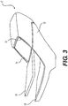
- One such light projector unit 30 is shown in Figure 3 and comprises a light housing 32 including one or more bulbs and internally configured reflective surfaces (not shown), and a front cover 34 that may include lensing elements.
- the unit 30 can be provided as a sealed unit. Alternatively, one or more bulbs may be replaceable.
- the unit 30 can be made so as to comply with regulatory requirements for road use, such as size, power, controllability for brightness and beam shape, etc.
- the housing 32 is mounted on a holder 36 that is shaped to correspond to the surface of the body 10.
- the holder has a pair of lateral support arms 38 for connection with an operating mechanism (not shown).
- the front of the body 10 includes transparent shield portions 40 located at its left and right extremities.
- a light projector unit housing cavity 42 is located behind each shield portion and is dimensioned so that the light housing 32 can fit inside.
- movement of the units 30 is achieved by a deployment mechanism comprising electric motor drives (not shown) housed in the front part of the body 10 acting on the lateral support arms 38. Operation of the deployment mechanism can be used to move the lighting units 30 between a first position in which each lighting unit is positioned within a housing cavity 42 behind the transparent shield portions 40, and a second position, in which the lighting units 30 are extended laterally from the body 10 so as to lie close to the inner edge of the fender 27 when the wheels are extended for road use.
- a deployment mechanism comprising electric motor drives (not shown) housed in the front part of the body 10 acting on the lateral support arms 38. Operation of the deployment mechanism can be used to move the lighting units 30 between a first position in which each lighting unit is positioned within a housing cavity 42 behind the transparent shield portions 40, and a second position, in which the lighting units 30 are extended laterally from the body 10 so as to lie close to the inner edge of the fender 27 when the wheels are extended for road use.
- the lighting units 30 can be positioned in the second position. In this way the projected light beams can provide optimized illumination of the road ahead when driving at night or in reduced visibility situations.
- the position of the units can comply with road use regulations such as maximum and minimum heights, and minimum distance from the outer edges of the vehicle.
- the wings 16 When the vehicle is initially configured for flight, the wings 16 are extended.
- the lighting units 30 are retraced behind the shield portions 40. Because the shield portions are transparent, the lighting units 32 can still be operated as taxiing lights to illuminate the ground ahead of the vehicle as is maneuvers ready for takeoff. However, by positioning the lights behind the shields 40, the drag is reduced.
- the vehicle will taxi and takeoff with the wheels 26 extended. Once airborne, the wheels and fenders 27 can be retracted, the outer surfaces of the holder 36 and fender 27 aligning with the outer surface of the body 10 to provide a reduced drag profile.
- the wheels 26 and fenders 27 can be extended and, if necessary, the lighting units 30 operated from behind the shields 40 to illuminate the ground ahead.
- the lighting units 30 can continue to operate in this fashion until the vehicle taxis to a halt and is reconfigured for road use, at which point the lighting units are extended to the second position as described above.
- the shield portions may be opaque and separate landing/taxiing lights provided for air use; lighting units may also be provided on the fenders; and direction indicators may be provided as part of the lighting units and/or separately.
Landscapes
- Engineering & Computer Science (AREA)
- Mechanical Engineering (AREA)
- Aviation & Aerospace Engineering (AREA)
- Transportation (AREA)
- Lighting Device Outwards From Vehicle And Optical Signal (AREA)
Abstract

Description
- This invention relates to vehicles that are configurable for air use (flying) and road use (driving). Such vehicles are commonly known as flying cars or roadable aircraft (hereafter "flying cars"). In particular, the invention relates to a configurable light unit that can be deployed in different positions for road use and air use.
- There have been a number of previous proposals for flying car designs, i.e. vehicles that can be fully compliant with legal and practical requirements for both road and flight use. Examples include the Terrafugia Transition (
WO 2007/114877 ), the Carplane (http://carplane.de/ ), the AeroMobil (WO 2013/032409 ), and the Moller Skycar (http://moller.com/ ). - Road use regulations typically require the presence of headlamps or light projector units at the front of the vehicle that are operable to project a beam of predefined pattern ahead of the vehicle to assist operation in low light conditions. Such regulations often prescribe maximum and minimum heights, and minimum distances from the outer extremities of the vehicle, as well as beam pattern and brightness. The requirement for the position of the lighting projector units can often be such that it compromises the frontal aspect of the vehicle and provides extra drag detrimental to aerodynamic performance. Alternatively, lighting projector units housed within the vehicle body are often compromised in lighting performance.
- This invention is an attempt to provide a light deployment that is optimized for road use while allowing for reduced drag in flight.
- A first aspect of the invention provides a vehicle configurable for air or road use, comprising: a body; a pair of road wheels located on either side of a front region of the body and moveable between a first configuration in which the wheels are positioned close to the body for air use, and a second configuration in which the wheels are extended laterally from the body for supporting the body when configured for road use, the spacing between the wheels being greater in the second configuration than in the first configuration; and a pair of light projector units mounted near the front of the body; wherein the light projector units are mounted so as to be moveable between a first position in which the light units are positioned close to the body, and a second position in which the light units are extended laterally from the body, the spacing between the light projector units being greater in the second position than in the first position.
- In addition to the body, the vehicle can also comprise a pair of wings moveable between a folded position for road use and an extended position for air use; a tail structure; and moveable control surfaces on the wings and tail for air use. In some embodiments, the pair of road wheels are driven, in which case a common motor can used to drive to both the pair of road wheels and a propeller.
- The front region of the body can further comprise a shield, and each light projector unit can be positioned behind a respective shield portion when in the first position. The shield portions can be transparent.
- In some embodiments, the vehicle further comprises a fender associated with each road wheel, the fenders being movable with the wheels so as to maintain their relative position when in the first and second configurations. The outermost part of the light projector units can be closer to the body than the outermost parts of the fenders when the wheels are in the second configuration and the light projector units are in the second position.
- The light projector units can be provided with an independent deployment mechanism such that movement of the light projector units between the first and second positions is independent of movement of the wheels between the first and second configurations.
- Each light projector unit can be mounted on a carrier configured such that the outer part of each carrier is substantially aligned with an adjacent surface of the body when in the first position.
- The light projector units can be operated as landing and taxi lights when in the first position, and as headlamps for road use when in the second position.
- A second aspect of the invention provides methods of operating the vehicle according to the first aspect.
- One method of operating the vehicle to transition between a road use configuration in which the wheels are in the second configuration and the light projector units are in the second position, and an air use configuration in which the wheels are in the first configuration and the light projector units are in the first position, comprises: moving the light projector units from the second position to the first position while the wheels are in contact with the ground; operating the vehicle to take off from the ground; and moving the wheels from the second configuration to the first configuration.
- One method of operating the vehicle to transition between an air use configuration in which the wheels are in the first configuration and the light projector units are in the first position, and a road use configuration in which the wheels are in the second configuration and the light projector units are in the second position, comprises: moving the wheels from the first configuration to the second configuration which the vehicle is in the air; operating the vehicle to land on the ground; and moving the light projector units from the first position to the second position when the wheels are in contact with the ground.
- Further variations can be made within the scope of the invention.
-
Figure 1 shows a front perspective view of a flying car in a flight configuration; -
Figure 2 shows a front perspective view of a flying car in a road use configuration; -
Figure 3 shows details of a light projector unit used in the vehicle ofFigures 1 and 2 . - Referring to
Figures 1 and 2 , an aircraft comprising a convertible vehicle (a flying car) is shown, in a flight configuration (Figure 1 ) and a road use configuration (Figure 2 ). The flying car comprises abody structure 10 providing acrew compartment 12 and housing a motor (not shown) and propeller shaft (not shown) that extends from the motor to the rear 14 of thebody structure 10, where the propeller is mounted as is described below.Wings 16 for providing lift and control (via ailerons, not shown) are mounted at the top of thebody 10 immediately behind thecrew compartment 12. Thewings 16 can be moved between an extended position for flight use (Figure 1 ), and a folded position for road use (Figure 2 ). In the folded position, the wings lie along the top of thebody 10, the long axis of the wings lying substantially parallel to the long axis of thebody 10. The folding mechanism is substantially as described inWO 2013/03240 -
Front wheels 26 are mounted on thebody structure 10. The front wheels are both steerable and driven. Eachwheel 26 has an associatedfender 27. In addition, thefront wheels 26 andfenders 27 can be moved between a retracted position (Figure 1 ) in which they are positioned close to thebody 10, thefenders 27 fitting closely with the outer surface of thebody 10, to reduce drag in flight; and an open position (Figure 2 ) in which they are positioned for improved traction and control for road use. In the open position, thefenders 27 can be positioned with respect to thewheels 26 so as to comply with road use regulatory requirements with regard to exposure of the wheels. It is also possible to include marker lights and direction indicator repeaters on thefenders 27. -
Light projector units 30', 30" are provided at the front of thebody 10 and are operable to project beams of light in a predetermined direction and having a predetermined shape. One suchlight projector unit 30 is shown inFigure 3 and comprises alight housing 32 including one or more bulbs and internally configured reflective surfaces (not shown), and afront cover 34 that may include lensing elements. Theunit 30 can be provided as a sealed unit. Alternatively, one or more bulbs may be replaceable. Theunit 30 can be made so as to comply with regulatory requirements for road use, such as size, power, controllability for brightness and beam shape, etc. Thehousing 32 is mounted on a holder 36 that is shaped to correspond to the surface of thebody 10. The holder has a pair oflateral support arms 38 for connection with an operating mechanism (not shown). - The front of the
body 10 includestransparent shield portions 40 located at its left and right extremities. A light projectorunit housing cavity 42 is located behind each shield portion and is dimensioned so that thelight housing 32 can fit inside. - In use, movement of the
units 30 is achieved by a deployment mechanism comprising electric motor drives (not shown) housed in the front part of thebody 10 acting on thelateral support arms 38. Operation of the deployment mechanism can be used to move thelighting units 30 between a first position in which each lighting unit is positioned within ahousing cavity 42 behind thetransparent shield portions 40, and a second position, in which thelighting units 30 are extended laterally from thebody 10 so as to lie close to the inner edge of thefender 27 when the wheels are extended for road use. - When the vehicle is on the ground and configured for road use, the
lighting units 30 can be positioned in the second position. In this way the projected light beams can provide optimized illumination of the road ahead when driving at night or in reduced visibility situations. In addition, the position of the units can comply with road use regulations such as maximum and minimum heights, and minimum distance from the outer edges of the vehicle. - When the vehicle is initially configured for flight, the
wings 16 are extended. Thelighting units 30 are retraced behind theshield portions 40. Because the shield portions are transparent, thelighting units 32 can still be operated as taxiing lights to illuminate the ground ahead of the vehicle as is maneuvers ready for takeoff. However, by positioning the lights behind theshields 40, the drag is reduced. The vehicle will taxi and takeoff with thewheels 26 extended. Once airborne, the wheels andfenders 27 can be retracted, the outer surfaces of the holder 36 andfender 27 aligning with the outer surface of thebody 10 to provide a reduced drag profile. - When the vehicle is to land, the
wheels 26 andfenders 27 can be extended and, if necessary, thelighting units 30 operated from behind theshields 40 to illuminate the ground ahead. Thelighting units 30 can continue to operate in this fashion until the vehicle taxis to a halt and is reconfigured for road use, at which point the lighting units are extended to the second position as described above. - Various changes can be made while remaining within the scope of the invention. For example, the shield portions may be opaque and separate landing/taxiing lights provided for air use; lighting units may also be provided on the fenders; and direction indicators may be provided as part of the lighting units and/or separately.
Claims (10)
- A vehicle configurable for air or road use, comprising:a body;a pair of road wheels located on either side of a front region of the body and moveable between a first configuration in which the wheels are positioned close to the body for air use, and a second configuration in which the wheels are extended laterally from the body for supporting the body when configured for road use, the spacing between the wheels being greater in the second configuration than in the first configuration; anda pair of light projector units mounted near the front of the body;wherein the light projector units are mounted so as to be moveable between a first position in which the light units are positioned close to the body, and a second position in which the light units are extended laterally from the body, the spacing between the light projector units being greater in the second position than in the first position.
- A vehicle as claimed in claim 1, wherein the front region of the body further comprises a shield, and wherein each light projector unit is positioned behind a respective shield portion when in the first position.
- A vehicle as claimed in claim 2, wherein the shield portions are transparent.
- A vehicle as claimed in claim 1, 2, or 3, further comprising a fender associated with each road wheel, the fenders being movable with the wheels so as to maintain their relative position when in the first and second configurations.
- A vehicle as claimed in claim 4, wherein the outermost part of the light projector units are closer to the body than the outermost parts of the fenders when the wheels are in the second configuration and the light projector units are in the second position.
- A vehicle as claimed in any preceding claim, wherein the light projector units are provided with an independent deployment mechanism such that movement of the light projector units between the first and second positions is independent of movement of the wheels between the first and second configurations.
- A vehicle as claimed in any preceding claim, wherein each light projector unit is mounted on a carrier configured such that the outer part of each carrier is substantially aligned with an adjacent surface of the body when in the first position.
- A vehicle as claimed in any preceding claim, wherein the light projector units are operable as landing and taxi lights when in the first position, and as headlamps for road use when in the second position.
- A method of operating a vehicle as claimed in any preceding claim to transition between a road use configuration in which the wheels are in the second configuration and the light projector units are in the second position, and an air use configuration in which the wheels are in the first configuration and the light projector units are in the first position, comprising:moving the light projector units from the second position to the first position while the wheels are in contact with the ground;operating the vehicle to take off from the ground; andmoving the wheels from the second configuration to the first configuration.
- A method of operating a vehicle as claimed in any of claims 1 - 8 to transition between an air use configuration in which the wheels are in the first configuration and the light projector units are in the first position, and a road use configuration in which the wheels are in the second configuration and the light projector units are in the second position, comprising:moving the wheels from the first configuration to the second configuration which the vehicle is in the air;operating the vehicle to land the ground; andmoving the light projector units from the first position to the second position when the wheels are in contact with the ground.
Priority Applications (2)
| Application Number | Priority Date | Filing Date | Title |
|---|---|---|---|
| EP16203806.1A EP3335935B1 (en) | 2016-12-13 | 2016-12-13 | Configurable lights for flying car |
| PCT/EP2017/082481 WO2018108944A1 (en) | 2016-12-13 | 2017-12-12 | Configurable lights for flying car |
Applications Claiming Priority (1)
| Application Number | Priority Date | Filing Date | Title |
|---|---|---|---|
| EP16203806.1A EP3335935B1 (en) | 2016-12-13 | 2016-12-13 | Configurable lights for flying car |
Publications (2)
| Publication Number | Publication Date |
|---|---|
| EP3335935A1 true EP3335935A1 (en) | 2018-06-20 |
| EP3335935B1 EP3335935B1 (en) | 2019-11-13 |
Family
ID=57609681
Family Applications (1)
| Application Number | Title | Priority Date | Filing Date |
|---|---|---|---|
| EP16203806.1A Not-in-force EP3335935B1 (en) | 2016-12-13 | 2016-12-13 | Configurable lights for flying car |
Country Status (2)
| Country | Link |
|---|---|
| EP (1) | EP3335935B1 (en) |
| WO (1) | WO2018108944A1 (en) |
Cited By (2)
| Publication number | Priority date | Publication date | Assignee | Title |
|---|---|---|---|---|
| WO2020101778A3 (en) * | 2018-08-14 | 2020-08-06 | Everon Corporation | Personal auto-craft |
| US12545384B2 (en) | 2020-03-19 | 2026-02-10 | Everon Corporation | Hubless propulsion unit |
Families Citing this family (1)
| Publication number | Priority date | Publication date | Assignee | Title |
|---|---|---|---|---|
| CN114228417B (en) * | 2022-01-28 | 2023-04-18 | 广东汇天航空航天科技有限公司 | Rear body structure of hovercar and hovercar |
Citations (7)
| Publication number | Priority date | Publication date | Assignee | Title |
|---|---|---|---|---|
| FR1475636A (en) * | 1965-06-24 | 1967-04-07 | Further development of motor vehicles and corresponding accessory lighting device | |
| FR2430870A1 (en) * | 1978-07-10 | 1980-02-08 | Caterpillar Tractor Co | RETRACTABLE LIGHT DEVICE FOR VEHICLES |
| US5243503A (en) * | 1992-09-14 | 1993-09-07 | Hu Chiu S | Fog-light assembly |
| US5355131A (en) * | 1992-10-07 | 1994-10-11 | Grimes Aerospace Company | Aircraft landing light |
| WO2007114877A2 (en) | 2006-01-06 | 2007-10-11 | Terrafugia, Inc. | Roadable aircraft with folding wings and integrated bumpers and lighting |
| WO2013003240A2 (en) | 2011-06-28 | 2013-01-03 | Microsoft Corporation | Summarization of conversation threads |
| WO2013032409A1 (en) | 2011-08-30 | 2013-03-07 | Aeromobil, S.R.O. | Transformation method of hybrid transportation vehicle for ground and air, and hybrid transportation vehicle itself |
Family Cites Families (2)
| Publication number | Priority date | Publication date | Assignee | Title |
|---|---|---|---|---|
| DE7129169U (en) * | 1971-07-29 | 1971-12-23 | International Harvester Co Mbh | DEVICE FOR FIXING THE HEADLIGHTS OF VEHICLES, IN PARTICULAR FOR VINEYARD AND FRUIT TOWING |
| EP1114748A3 (en) * | 2000-01-07 | 2004-01-02 | Hans Dominik | Lighting device |
-
2016
- 2016-12-13 EP EP16203806.1A patent/EP3335935B1/en not_active Not-in-force
-
2017
- 2017-12-12 WO PCT/EP2017/082481 patent/WO2018108944A1/en not_active Ceased
Patent Citations (7)
| Publication number | Priority date | Publication date | Assignee | Title |
|---|---|---|---|---|
| FR1475636A (en) * | 1965-06-24 | 1967-04-07 | Further development of motor vehicles and corresponding accessory lighting device | |
| FR2430870A1 (en) * | 1978-07-10 | 1980-02-08 | Caterpillar Tractor Co | RETRACTABLE LIGHT DEVICE FOR VEHICLES |
| US5243503A (en) * | 1992-09-14 | 1993-09-07 | Hu Chiu S | Fog-light assembly |
| US5355131A (en) * | 1992-10-07 | 1994-10-11 | Grimes Aerospace Company | Aircraft landing light |
| WO2007114877A2 (en) | 2006-01-06 | 2007-10-11 | Terrafugia, Inc. | Roadable aircraft with folding wings and integrated bumpers and lighting |
| WO2013003240A2 (en) | 2011-06-28 | 2013-01-03 | Microsoft Corporation | Summarization of conversation threads |
| WO2013032409A1 (en) | 2011-08-30 | 2013-03-07 | Aeromobil, S.R.O. | Transformation method of hybrid transportation vehicle for ground and air, and hybrid transportation vehicle itself |
Cited By (4)
| Publication number | Priority date | Publication date | Assignee | Title |
|---|---|---|---|---|
| WO2020101778A3 (en) * | 2018-08-14 | 2020-08-06 | Everon Corporation | Personal auto-craft |
| CN112839829A (en) * | 2018-08-14 | 2021-05-25 | 埃弗隆股份有限公司 | Private Autonomous Aircraft |
| US12077027B2 (en) | 2018-08-14 | 2024-09-03 | Everon Corporation | Personal auto-craft having automobile and vertical take-off configurations |
| US12545384B2 (en) | 2020-03-19 | 2026-02-10 | Everon Corporation | Hubless propulsion unit |
Also Published As
| Publication number | Publication date |
|---|---|
| EP3335935B1 (en) | 2019-11-13 |
| WO2018108944A1 (en) | 2018-06-21 |
Similar Documents
| Publication | Publication Date | Title |
|---|---|---|
| US20080137353A1 (en) | Multi-mode exterior lighting architectures for aircraft | |
| EP3284684B1 (en) | Exterior airplane light unit and method of warning ground personnel | |
| ES2630202T3 (en) | Hybrid transportation vehicle for land and air, and method of transformation of such vehicle | |
| KR20150115857A (en) | Downwardly extending wing tip device | |
| EP3626631B1 (en) | Aircraft light for a foldable wing tip, aircraft comprising and method of operating such aircraft light | |
| EP3335935B1 (en) | Configurable lights for flying car | |
| WO2007114877A2 (en) | Roadable aircraft with folding wings and integrated bumpers and lighting | |
| BG111231A (en) | Road aircraft | |
| KR100945065B1 (en) | Collision-avoidance device for aircraft moving on land and aircraft with same | |
| ES2938352T3 (en) | Aircraft beacon light and aircraft comprising an aircraft beacon light | |
| US6669357B2 (en) | Surface illumination system of an aircraft and like vehicles | |
| US10836506B2 (en) | Exterior aircraft light, aircraft wing comprising the same, and method of operating an exterior aircraft light | |
| EP3315400A1 (en) | Folding propeller | |
| US20190283514A1 (en) | Configurable tail for flying car | |
| US8245973B2 (en) | Methods and systems for improving aircraft visibility | |
| EP3643620B1 (en) | Aircraft wing, aircraft, and method of supplementing an aircraft beacon light system | |
| DE102009060611A1 (en) | Vehicle i.e. inflatable flight, for transportation on public road, has inflatable and/or telescopic profile segments swiveling out bearing surface and forming fully span width and profile geometry | |
| US9650154B2 (en) | Aircraft landing gear assemblies with non-rotating light element clusters | |
| KR20160072726A (en) | Vertical take-off and landing type flying body with traveling ground | |
| EP0976654A1 (en) | Helicopter landing lights assembly | |
| KR20220045471A (en) | Personal Air Vehicle Having Vacuum Box Type Flight Altitude Lamp | |
| RU143819U1 (en) | VEHICLE AND LAND VEHICLE VEHICLE | |
| RU149359U1 (en) | EXTENDABLE FRONT SPOILER FOR VEHICLE | |
| RU2129504C1 (en) | Vehicle | |
| CN102126556A (en) | Vertical take-off and landing small-sized airplane |
Legal Events
| Date | Code | Title | Description |
|---|---|---|---|
| PUAI | Public reference made under article 153(3) epc to a published international application that has entered the european phase |
Free format text: ORIGINAL CODE: 0009012 |
|
| STAA | Information on the status of an ep patent application or granted ep patent |
Free format text: STATUS: THE APPLICATION HAS BEEN PUBLISHED |
|
| AK | Designated contracting states |
Kind code of ref document: A1 Designated state(s): AL AT BE BG CH CY CZ DE DK EE ES FI FR GB GR HR HU IE IS IT LI LT LU LV MC MK MT NL NO PL PT RO RS SE SI SK SM TR |
|
| AX | Request for extension of the european patent |
Extension state: BA ME |
|
| STAA | Information on the status of an ep patent application or granted ep patent |
Free format text: STATUS: REQUEST FOR EXAMINATION WAS MADE |
|
| 17P | Request for examination filed |
Effective date: 20181220 |
|
| RBV | Designated contracting states (corrected) |
Designated state(s): AL AT BE BG CH CY CZ DE DK EE ES FI FR GB GR HR HU IE IS IT LI LT LU LV MC MK MT NL NO PL PT RO RS SE SI SK SM TR |
|
| GRAP | Despatch of communication of intention to grant a patent |
Free format text: ORIGINAL CODE: EPIDOSNIGR1 |
|
| STAA | Information on the status of an ep patent application or granted ep patent |
Free format text: STATUS: GRANT OF PATENT IS INTENDED |
|
| INTG | Intention to grant announced |
Effective date: 20190603 |
|
| GRAS | Grant fee paid |
Free format text: ORIGINAL CODE: EPIDOSNIGR3 |
|
| GRAA | (expected) grant |
Free format text: ORIGINAL CODE: 0009210 |
|
| STAA | Information on the status of an ep patent application or granted ep patent |
Free format text: STATUS: THE PATENT HAS BEEN GRANTED |
|
| AK | Designated contracting states |
Kind code of ref document: B1 Designated state(s): AL AT BE BG CH CY CZ DE DK EE ES FI FR GB GR HR HU IE IS IT LI LT LU LV MC MK MT NL NO PL PT RO RS SE SI SK SM TR |
|
| REG | Reference to a national code |
Ref country code: CH Ref legal event code: EP Ref country code: AT Ref legal event code: REF Ref document number: 1201330 Country of ref document: AT Kind code of ref document: T Effective date: 20191115 |
|
| REG | Reference to a national code |
Ref country code: DE Ref legal event code: R096 Ref document number: 602016024199 Country of ref document: DE |
|
| REG | Reference to a national code |
Ref country code: IE Ref legal event code: FG4D |
|
| PGFP | Annual fee paid to national office [announced via postgrant information from national office to epo] |
Ref country code: DE Payment date: 20191203 Year of fee payment: 4 |
|
| REG | Reference to a national code |
Ref country code: NL Ref legal event code: MP Effective date: 20191113 |
|
| REG | Reference to a national code |
Ref country code: LT Ref legal event code: MG4D |
|
| PG25 | Lapsed in a contracting state [announced via postgrant information from national office to epo] |
Ref country code: PT Free format text: LAPSE BECAUSE OF FAILURE TO SUBMIT A TRANSLATION OF THE DESCRIPTION OR TO PAY THE FEE WITHIN THE PRESCRIBED TIME-LIMIT Effective date: 20200313 Ref country code: PL Free format text: LAPSE BECAUSE OF FAILURE TO SUBMIT A TRANSLATION OF THE DESCRIPTION OR TO PAY THE FEE WITHIN THE PRESCRIBED TIME-LIMIT Effective date: 20191113 Ref country code: SE Free format text: LAPSE BECAUSE OF FAILURE TO SUBMIT A TRANSLATION OF THE DESCRIPTION OR TO PAY THE FEE WITHIN THE PRESCRIBED TIME-LIMIT Effective date: 20191113 Ref country code: LV Free format text: LAPSE BECAUSE OF FAILURE TO SUBMIT A TRANSLATION OF THE DESCRIPTION OR TO PAY THE FEE WITHIN THE PRESCRIBED TIME-LIMIT Effective date: 20191113 Ref country code: FI Free format text: LAPSE BECAUSE OF FAILURE TO SUBMIT A TRANSLATION OF THE DESCRIPTION OR TO PAY THE FEE WITHIN THE PRESCRIBED TIME-LIMIT Effective date: 20191113 Ref country code: BG Free format text: LAPSE BECAUSE OF FAILURE TO SUBMIT A TRANSLATION OF THE DESCRIPTION OR TO PAY THE FEE WITHIN THE PRESCRIBED TIME-LIMIT Effective date: 20200213 Ref country code: NO Free format text: LAPSE BECAUSE OF FAILURE TO SUBMIT A TRANSLATION OF THE DESCRIPTION OR TO PAY THE FEE WITHIN THE PRESCRIBED TIME-LIMIT Effective date: 20200213 Ref country code: GR Free format text: LAPSE BECAUSE OF FAILURE TO SUBMIT A TRANSLATION OF THE DESCRIPTION OR TO PAY THE FEE WITHIN THE PRESCRIBED TIME-LIMIT Effective date: 20200214 Ref country code: LT Free format text: LAPSE BECAUSE OF FAILURE TO SUBMIT A TRANSLATION OF THE DESCRIPTION OR TO PAY THE FEE WITHIN THE PRESCRIBED TIME-LIMIT Effective date: 20191113 Ref country code: NL Free format text: LAPSE BECAUSE OF FAILURE TO SUBMIT A TRANSLATION OF THE DESCRIPTION OR TO PAY THE FEE WITHIN THE PRESCRIBED TIME-LIMIT Effective date: 20191113 |
|
| PG25 | Lapsed in a contracting state [announced via postgrant information from national office to epo] |
Ref country code: HR Free format text: LAPSE BECAUSE OF FAILURE TO SUBMIT A TRANSLATION OF THE DESCRIPTION OR TO PAY THE FEE WITHIN THE PRESCRIBED TIME-LIMIT Effective date: 20191113 Ref country code: IS Free format text: LAPSE BECAUSE OF FAILURE TO SUBMIT A TRANSLATION OF THE DESCRIPTION OR TO PAY THE FEE WITHIN THE PRESCRIBED TIME-LIMIT Effective date: 20200313 Ref country code: RS Free format text: LAPSE BECAUSE OF FAILURE TO SUBMIT A TRANSLATION OF THE DESCRIPTION OR TO PAY THE FEE WITHIN THE PRESCRIBED TIME-LIMIT Effective date: 20191113 |
|
| PG25 | Lapsed in a contracting state [announced via postgrant information from national office to epo] |
Ref country code: AL Free format text: LAPSE BECAUSE OF FAILURE TO SUBMIT A TRANSLATION OF THE DESCRIPTION OR TO PAY THE FEE WITHIN THE PRESCRIBED TIME-LIMIT Effective date: 20191113 |
|
| PG25 | Lapsed in a contracting state [announced via postgrant information from national office to epo] |
Ref country code: RO Free format text: LAPSE BECAUSE OF FAILURE TO SUBMIT A TRANSLATION OF THE DESCRIPTION OR TO PAY THE FEE WITHIN THE PRESCRIBED TIME-LIMIT Effective date: 20191113 Ref country code: CZ Free format text: LAPSE BECAUSE OF FAILURE TO SUBMIT A TRANSLATION OF THE DESCRIPTION OR TO PAY THE FEE WITHIN THE PRESCRIBED TIME-LIMIT Effective date: 20191113 Ref country code: EE Free format text: LAPSE BECAUSE OF FAILURE TO SUBMIT A TRANSLATION OF THE DESCRIPTION OR TO PAY THE FEE WITHIN THE PRESCRIBED TIME-LIMIT Effective date: 20191113 Ref country code: DK Free format text: LAPSE BECAUSE OF FAILURE TO SUBMIT A TRANSLATION OF THE DESCRIPTION OR TO PAY THE FEE WITHIN THE PRESCRIBED TIME-LIMIT Effective date: 20191113 Ref country code: ES Free format text: LAPSE BECAUSE OF FAILURE TO SUBMIT A TRANSLATION OF THE DESCRIPTION OR TO PAY THE FEE WITHIN THE PRESCRIBED TIME-LIMIT Effective date: 20191113 |
|
| REG | Reference to a national code |
Ref country code: CH Ref legal event code: PL |
|
| REG | Reference to a national code |
Ref country code: DE Ref legal event code: R097 Ref document number: 602016024199 Country of ref document: DE |
|
| REG | Reference to a national code |
Ref country code: AT Ref legal event code: MK05 Ref document number: 1201330 Country of ref document: AT Kind code of ref document: T Effective date: 20191113 |
|
| REG | Reference to a national code |
Ref country code: BE Ref legal event code: MM Effective date: 20191231 |
|
| PG25 | Lapsed in a contracting state [announced via postgrant information from national office to epo] |
Ref country code: SK Free format text: LAPSE BECAUSE OF FAILURE TO SUBMIT A TRANSLATION OF THE DESCRIPTION OR TO PAY THE FEE WITHIN THE PRESCRIBED TIME-LIMIT Effective date: 20191113 Ref country code: SM Free format text: LAPSE BECAUSE OF FAILURE TO SUBMIT A TRANSLATION OF THE DESCRIPTION OR TO PAY THE FEE WITHIN THE PRESCRIBED TIME-LIMIT Effective date: 20191113 Ref country code: MC Free format text: LAPSE BECAUSE OF FAILURE TO SUBMIT A TRANSLATION OF THE DESCRIPTION OR TO PAY THE FEE WITHIN THE PRESCRIBED TIME-LIMIT Effective date: 20191113 |
|
| PLBE | No opposition filed within time limit |
Free format text: ORIGINAL CODE: 0009261 |
|
| STAA | Information on the status of an ep patent application or granted ep patent |
Free format text: STATUS: NO OPPOSITION FILED WITHIN TIME LIMIT |
|
| 26N | No opposition filed |
Effective date: 20200814 |
|
| PG25 | Lapsed in a contracting state [announced via postgrant information from national office to epo] |
Ref country code: FR Free format text: LAPSE BECAUSE OF NON-PAYMENT OF DUE FEES Effective date: 20200113 Ref country code: LU Free format text: LAPSE BECAUSE OF NON-PAYMENT OF DUE FEES Effective date: 20191213 Ref country code: IE Free format text: LAPSE BECAUSE OF NON-PAYMENT OF DUE FEES Effective date: 20191213 |
|
| PG25 | Lapsed in a contracting state [announced via postgrant information from national office to epo] |
Ref country code: CH Free format text: LAPSE BECAUSE OF NON-PAYMENT OF DUE FEES Effective date: 20191231 Ref country code: LI Free format text: LAPSE BECAUSE OF NON-PAYMENT OF DUE FEES Effective date: 20191231 Ref country code: BE Free format text: LAPSE BECAUSE OF NON-PAYMENT OF DUE FEES Effective date: 20191231 Ref country code: AT Free format text: LAPSE BECAUSE OF FAILURE TO SUBMIT A TRANSLATION OF THE DESCRIPTION OR TO PAY THE FEE WITHIN THE PRESCRIBED TIME-LIMIT Effective date: 20191113 Ref country code: SI Free format text: LAPSE BECAUSE OF FAILURE TO SUBMIT A TRANSLATION OF THE DESCRIPTION OR TO PAY THE FEE WITHIN THE PRESCRIBED TIME-LIMIT Effective date: 20191113 |
|
| PG25 | Lapsed in a contracting state [announced via postgrant information from national office to epo] |
Ref country code: IT Free format text: LAPSE BECAUSE OF FAILURE TO SUBMIT A TRANSLATION OF THE DESCRIPTION OR TO PAY THE FEE WITHIN THE PRESCRIBED TIME-LIMIT Effective date: 20191113 |
|
| PG25 | Lapsed in a contracting state [announced via postgrant information from national office to epo] |
Ref country code: CY Free format text: LAPSE BECAUSE OF FAILURE TO SUBMIT A TRANSLATION OF THE DESCRIPTION OR TO PAY THE FEE WITHIN THE PRESCRIBED TIME-LIMIT Effective date: 20191113 |
|
| REG | Reference to a national code |
Ref country code: DE Ref legal event code: R119 Ref document number: 602016024199 Country of ref document: DE |
|
| PG25 | Lapsed in a contracting state [announced via postgrant information from national office to epo] |
Ref country code: MT Free format text: LAPSE BECAUSE OF FAILURE TO SUBMIT A TRANSLATION OF THE DESCRIPTION OR TO PAY THE FEE WITHIN THE PRESCRIBED TIME-LIMIT Effective date: 20191113 Ref country code: HU Free format text: LAPSE BECAUSE OF FAILURE TO SUBMIT A TRANSLATION OF THE DESCRIPTION OR TO PAY THE FEE WITHIN THE PRESCRIBED TIME-LIMIT; INVALID AB INITIO Effective date: 20161213 |
|
| GBPC | Gb: european patent ceased through non-payment of renewal fee |
Effective date: 20201213 |
|
| PG25 | Lapsed in a contracting state [announced via postgrant information from national office to epo] |
Ref country code: DE Free format text: LAPSE BECAUSE OF NON-PAYMENT OF DUE FEES Effective date: 20210701 Ref country code: GB Free format text: LAPSE BECAUSE OF NON-PAYMENT OF DUE FEES Effective date: 20201213 |
|
| PG25 | Lapsed in a contracting state [announced via postgrant information from national office to epo] |
Ref country code: TR Free format text: LAPSE BECAUSE OF FAILURE TO SUBMIT A TRANSLATION OF THE DESCRIPTION OR TO PAY THE FEE WITHIN THE PRESCRIBED TIME-LIMIT Effective date: 20191113 |
|
| PG25 | Lapsed in a contracting state [announced via postgrant information from national office to epo] |
Ref country code: MK Free format text: LAPSE BECAUSE OF FAILURE TO SUBMIT A TRANSLATION OF THE DESCRIPTION OR TO PAY THE FEE WITHIN THE PRESCRIBED TIME-LIMIT Effective date: 20191113 |