EP3335866A1 - Tire with an asymmetric ply line and method of manufacturing - Google Patents
Tire with an asymmetric ply line and method of manufacturing Download PDFInfo
- Publication number
- EP3335866A1 EP3335866A1 EP17207400.7A EP17207400A EP3335866A1 EP 3335866 A1 EP3335866 A1 EP 3335866A1 EP 17207400 A EP17207400 A EP 17207400A EP 3335866 A1 EP3335866 A1 EP 3335866A1
- Authority
- EP
- European Patent Office
- Prior art keywords
- tire
- ply
- pair
- asymmetric
- symmetric
- Prior art date
- Legal status (The legal status is an assumption and is not a legal conclusion. Google has not performed a legal analysis and makes no representation as to the accuracy of the status listed.)
- Granted
Links
Images

Classifications
-
- B—PERFORMING OPERATIONS; TRANSPORTING
- B60—VEHICLES IN GENERAL
- B60C—VEHICLE TYRES; TYRE INFLATION; TYRE CHANGING; CONNECTING VALVES TO INFLATABLE ELASTIC BODIES IN GENERAL; DEVICES OR ARRANGEMENTS RELATED TO TYRES
- B60C9/00—Reinforcements or ply arrangement of pneumatic tyres
- B60C9/02—Carcasses
- B60C9/17—Carcasses asymmetric to the midcircumferential plane of the tyre
-
- B—PERFORMING OPERATIONS; TRANSPORTING
- B29—WORKING OF PLASTICS; WORKING OF SUBSTANCES IN A PLASTIC STATE IN GENERAL
- B29D—PRODUCING PARTICULAR ARTICLES FROM PLASTICS OR FROM SUBSTANCES IN A PLASTIC STATE
- B29D30/00—Producing pneumatic or solid tyres or parts thereof
- B29D30/06—Pneumatic tyres or parts thereof (e.g. produced by casting, moulding, compression moulding, injection moulding, centrifugal casting)
-
- B—PERFORMING OPERATIONS; TRANSPORTING
- B29—WORKING OF PLASTICS; WORKING OF SUBSTANCES IN A PLASTIC STATE IN GENERAL
- B29D—PRODUCING PARTICULAR ARTICLES FROM PLASTICS OR FROM SUBSTANCES IN A PLASTIC STATE
- B29D30/00—Producing pneumatic or solid tyres or parts thereof
- B29D30/06—Pneumatic tyres or parts thereof (e.g. produced by casting, moulding, compression moulding, injection moulding, centrifugal casting)
- B29D30/72—Side-walls
-
- B—PERFORMING OPERATIONS; TRANSPORTING
- B60—VEHICLES IN GENERAL
- B60C—VEHICLE TYRES; TYRE INFLATION; TYRE CHANGING; CONNECTING VALVES TO INFLATABLE ELASTIC BODIES IN GENERAL; DEVICES OR ARRANGEMENTS RELATED TO TYRES
- B60C3/00—Tyres characterised by the transverse section
- B60C3/06—Tyres characterised by the transverse section asymmetric
-
- B—PERFORMING OPERATIONS; TRANSPORTING
- B29—WORKING OF PLASTICS; WORKING OF SUBSTANCES IN A PLASTIC STATE IN GENERAL
- B29D—PRODUCING PARTICULAR ARTICLES FROM PLASTICS OR FROM SUBSTANCES IN A PLASTIC STATE
- B29D30/00—Producing pneumatic or solid tyres or parts thereof
- B29D30/06—Pneumatic tyres or parts thereof (e.g. produced by casting, moulding, compression moulding, injection moulding, centrifugal casting)
- B29D30/0601—Vulcanising tyres; Vulcanising presses for tyres
- B29D30/0606—Vulcanising moulds not integral with vulcanising presses
- B29D2030/0607—Constructional features of the moulds
Definitions
- the present invention relates to an improved tire, preferably a radial ply tire, and, more specifically, to an improved ply line of a radial ply passenger or truck tire and its method of manufacturing.
- a tire tread It is desirable for a tire tread to bear against the ground uniformly along its width, so that the load on the tire is evenly distributed.
- the portion of the tire's sidewalls near the ground bulge outward. If the tire is stiff along the shoulders, the sidewall bulge causes the center of the tread in contact with the ground to lift off the ground or merely to lose pressure against the ground.
- the stiff tire sidewall close to the shoulder acts like a lever, and the shoulder against the ground acts as its fulcrum. This "tread-lift” is aggravated by high bending stiffness of the shoulder area, and by a small ply line radius (e.g., sharp bend) in the shoulder.
- Heavy handling refers to severe driving conditions due to aggressive driving by a driver, such as sharp cornering and/or racing conditions.
- the tire shoulder area needs to have heavier gauge (e.g., thicker) rubber in both the tire shoulder and upper sidewall areas. This is required to provide a high tangential stiffness (e.g., resistance of tread rotation around tire axis relative to the beads) and a better durability in heavy handling.
- a heavy gauge leads to high bending stiffness especially in the shoulder area where the ply line radius is rather small. Hence, heavy handling tires are prone to tread-lift.
- the tread-lift issue has been conventionally mitigated by "decoupling grooves" in the tread in the tire shoulder areas, by increasing the radii of the adjacent contour-defining curves near the shoulder area, and by rendering the adjacent contour-defining curves non-tangential with each other at their meeting point. While alleviating the tread-lift issue, incorporating decoupling grooves in the shoulder areas reduces tangential stiffness and reduces tire in heavy handling tires.
- the invention relates to a tire in accordance with claim 1 and to a method in accordance with claim 8.
- a tire in accordance with the present invention has an axis of rotation, a cavity shape, a crown portion, a pair of beads, a tread, a pair of sidewalls, a pair of shoulder portions, and a carcass including a plurality of plies.
- Each ply has a cord.
- the tire is characterized by a path of the cord in at least one ply defining a ply line.
- the beads are both at the same radial position related to the axis of rotation with the pair of sidewalls being asymmetric.
- the pair of shoulder portions have an asymmetric construction and the cavity shape has a symmetric construction.
- the tire is cured from quasi-symmetric uncured tire in an asymmetric mold with a symmetric mold ring and sidewall plates having different shapes.
- the crown portion moves laterally when the tire is mounted on a symmetric rim and inflated.
- the ply line is asymmetric and one shoulder portion may have a radial position different from a radial position of the other shoulder portion.
- a system in accordance with the present invention includes a substantially symmetric green tire having an axis of rotation, an asymmetric curing mold, curing the substantially symmetric tire with the asymmetric mold to produce a cured tire such that a crown area of the cured tire moves laterally when the cured tire is mounted on a symmetrical rim and is inflated.
- an axial centerline of the crown area is axially offset a predetermined distance from an axial centerline of a rim on which the cured tire is mounted.
- the predetermined distance increases when the cured tire changes from an unloaded condition to a loaded condition.
- the cured tire is free of grooves in shoulder areas of the crown area.
- a method of manufacturing a pneumatic tire comprising: reparing a symmetric or quasi-symmetric uncured tire tire having an axis of rotation, a cavity shape, a crown portion, a pair of beads, a tread, a pair of sidewalls, a pair of shoulder portions, and a carcass including one or a plurality of plies, each ply having a cord, and a path of the cords in at least one ply defining a ply line; and curing the uncured tire in an asymmetric mold, the asymmetric mold having a symmetric mold ring but asymmetric sidewall plates having different shapes.
- Bead means an annular tensile member that is associated with holding the tire to the rim.
- the beads are wrapped by ply cords and shaped, with or without other reinforcement elements such as flippers, chippers, apexes or fillers, toe guards and chafers.
- Belt Structure or " Belts” means one or at least two annular layers or plies of parallel cords, woven or unwoven, underlying the tread, unanchored to the bead, and preferably having both left and right cord angles in the range from 0° to 45° with respect to the equatorial plane of the tire.
- Carcass means the tire structure apart from the belt structure, tread and underlay over the plies, but including the beads.
- Carcass cord means a ply cord.
- “Circumferential” means directions extending along the perimeter of the surface of the annular tread perpendicular to the axial direction.
- Core means one of the reinforcement strands which the plies in the tire comprise.
- Equatorial Plane or "EP” means the plane perpendicular to the tire's axis of rotation and passing through the center of its tread.
- “Lateral” means in the direction parallel with the tire axis.
- Loaded used as an adjective for any parameter refers to that parameter for a tire that is loaded, (e.g., inflated, mounted on a passenger or small truck, and resting on a surface).
- the tread profile of a passenger or small truck tire is generally flat in the loaded condition.
- “Meridional” refers to a tire profile cut along a plane that includes the tire's rotational axis.
- Plastic means a layer of rubber-coated parallel cords.
- Ring means in a direction orthogonal to the tire axis.
- Ring Ply Tire means a belted or circumferentially-restricted pneumatic passenger or small truck tire in which at least one ply has cords which extend from bead to bead and are laid at cord angles between 45° and 90° with respect to the equatorial plane of the tire.
- the term tire within the context of the present invention excludes motorcycle tires.
- Shader means the region where the sidewall meets the tread edge.
- “Shoulder Region” means the upper portion of sidewall just below the tread edge.
- the shoulder region of a passenger or small truck tire has a cavity radius of up to 60 millimeters (mm).
- the shoulder region is the part of the tire under this cavity radius and between two planes perpendicular to the ply and passing through the borders of this cavity radius.
- “Sidewall” is the portion of a tire between the tread and the bead.
- Tire footprint means the interface region in contact with the road surface while rotating under load. There is a vertical component acting in the "Z” direction, a longitudinal component acting in the "X” direction, and a lateral component acting in the "Y” direction.
- Unloaded used as an adjective for any parameter refers to that parameter for a tire that is unloaded, (e.g., inflated and not resting on a surface).
- the tread profile of a passenger or small truck tire is generally flat in the unloaded condition.
- the manufacturing of a tire in accordance with the present invention begins the manufacturing of green tire having a symmetrical green carcass or an at least substantially symmetrical green carcass. Afterwards, and in one aspect of the invention, this green tire is then cured in an asymmetrical mold thereby forming geometrically asymmetric sidewalls of the cured tire. This cured tire may then be inflated to produce an asymmetrical behavior of the cured tire while rotating and loaded. Such behavior generates an unbalance in carcass ply tension producing a beneficial asymmetrical force distribution within the tire footprint.
- the tension in the membrane, or carcass ply 100 is related to the air pressure (P) within the membrane by the below equation.
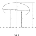
- the full belt package has a cured maximum width radius r w radially different by the distance between the two sidewalls (see Fig. 2 ).
- a radial inequality of tension during the inflation process moves the full belt package and crown area of the tire laterally.
- This difference ⁇ between the two radii r w1 , r w2 may be obtained by curing the tire in an asymmetric mold.
- Asymmetry can be lying in different levels between the two sidewalls and/or different curvatures between the two sidewalls.
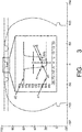
- FIG. 3 a measurement of the lateral displacement of the tire is shown.
- the reference point C is laterally located/moving during different steps of the inflating process.
- the reference point C is initially, at zero inflation pressure, located axially where the equatorial plane of the tire crosses the tire tread (in Fig. 3 : at a groove bottom).
- the line d1 is a horizontal line intersecting the radially innermost position of the tread (or the radially innermost position of a tread groove bottom) at the center line 200.
- the line d2 is a horizontal line intersecting the radially outermost position of the tread (or the two radially outermost edges of the tread groove) proximate the center line 200.
- the line d3 is a horizontal line positioned at 20% of the radial distance between line d1 and line d2 close to d1.
- the reference point A is the intersection of the line d3 and one sidewall of the center groove.
- the reference point B is the intersection of the line d3 and the axial center of the center groove.
- the reference point C is also the midpoint between reference points A and B.
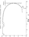
- the axial position of reference point C is monitored for each inflation pressure step.
- the lateral change of position of one of the sidewalls is determined.
- the maximum width of the sidewalls during the inflation pressure process is measured.
- the overall lateral change of position of the crown area may thereby be observed.
Landscapes
- Engineering & Computer Science (AREA)
- Mechanical Engineering (AREA)
- Tires In General (AREA)
- Moulds For Moulding Plastics Or The Like (AREA)
- Tyre Moulding (AREA)
Abstract
Description
- The present invention relates to an improved tire, preferably a radial ply tire, and, more specifically, to an improved ply line of a radial ply passenger or truck tire and its method of manufacturing.
- It is desirable for a tire tread to bear against the ground uniformly along its width, so that the load on the tire is evenly distributed. When a tire is loaded, the portion of the tire's sidewalls near the ground bulge outward. If the tire is stiff along the shoulders, the sidewall bulge causes the center of the tread in contact with the ground to lift off the ground or merely to lose pressure against the ground. The stiff tire sidewall close to the shoulder acts like a lever, and the shoulder against the ground acts as its fulcrum. This "tread-lift" is aggravated by high bending stiffness of the shoulder area, and by a small ply line radius (e.g., sharp bend) in the shoulder.
- The resulting bending stresses from the sidewalls to the tread cause inward buckling and lifting of the center portion of the tread off the ground, causing the center portion of the tread to bear little or none of the tire's load, which produces several issues. It degrades vehicle handling characteristics, especially in cornering. It increases tread wear near the shoulders and increases material fatigue under the tread due to the cycling of the bending stresses upon tire rotation, and hence shortens tire life or durability. Tread-lift is a problem whether the tread center actually lifts off the ground or merely loses pressure against the ground.
- "Heavy handling" refers to severe driving conditions due to aggressive driving by a driver, such as sharp cornering and/or racing conditions. For good heavy handling performance, the tire shoulder area needs to have heavier gauge (e.g., thicker) rubber in both the tire shoulder and upper sidewall areas. This is required to provide a high tangential stiffness (e.g., resistance of tread rotation around tire axis relative to the beads) and a better durability in heavy handling. However, a heavy gauge leads to high bending stiffness especially in the shoulder area where the ply line radius is rather small. Hence, heavy handling tires are prone to tread-lift.
- The tread-lift issue has been conventionally mitigated by "decoupling grooves" in the tread in the tire shoulder areas, by increasing the radii of the adjacent contour-defining curves near the shoulder area, and by rendering the adjacent contour-defining curves non-tangential with each other at their meeting point. While alleviating the tread-lift issue, incorporating decoupling grooves in the shoulder areas reduces tangential stiffness and reduces tire in heavy handling tires.
- The invention relates to a tire in accordance with claim 1 and to a method in accordance with claim 8.
- Dependent claims refer to preferred embodiments of the invention.
- A tire in accordance with the present invention has an axis of rotation, a cavity shape, a crown portion, a pair of beads, a tread, a pair of sidewalls, a pair of shoulder portions, and a carcass including a plurality of plies. Each ply has a cord. The tire is characterized by a path of the cord in at least one ply defining a ply line.
- According to another aspect of the tire, the beads are both at the same radial position related to the axis of rotation with the pair of sidewalls being asymmetric.
- According to still another aspect of the tire, the pair of shoulder portions have an asymmetric construction and the cavity shape has a symmetric construction.
- According to yet another aspect of the tire, the tire is cured from quasi-symmetric uncured tire in an asymmetric mold with a symmetric mold ring and sidewall plates having different shapes.
- According to still another aspect of the tire, the crown portion moves laterally when the tire is mounted on a symmetric rim and inflated.
- According to yet another aspect of the tire, the ply line is asymmetric and one shoulder portion may have a radial position different from a radial position of the other shoulder portion.
- A system in accordance with the present invention includes a substantially symmetric green tire having an axis of rotation, an asymmetric curing mold, curing the substantially symmetric tire with the asymmetric mold to produce a cured tire such that a crown area of the cured tire moves laterally when the cured tire is mounted on a symmetrical rim and is inflated.
- According to another aspect of the system, an axial centerline of the crown area is axially offset a predetermined distance from an axial centerline of a rim on which the cured tire is mounted.
- According to still another aspect of the system, the predetermined distance increases when the cured tire changes from an unloaded condition to a loaded condition.
- According to yet another aspect of the system, the cured tire is free of grooves in shoulder areas of the crown area.
- According to another aspect of the invention, a method of manufacturing a pneumatic tire is disclosed, the method comprising: reparing a symmetric or quasi-symmetric uncured tire tire having an axis of rotation, a cavity shape, a crown portion, a pair of beads, a tread, a pair of sidewalls, a pair of shoulder portions, and a carcass including one or a plurality of plies, each ply having a cord, and a path of the cords in at least one ply defining a ply line; and curing the uncured tire in an asymmetric mold, the asymmetric mold having a symmetric mold ring but asymmetric sidewall plates having different shapes.
- Reference will be made in detail to the example embodiments of the present invention, examples of which are illustrated in the accompanying drawings. The drawings are intended to be illustrative, not limiting. Certain elements in some of the drawings may be illustrated not-to-scale for illustrative clarity. The cross-sectional views presented herein may be in the form "near-sighted" cross-sectional views, omitting certain background lines that would otherwise be visible in a true cross-sectional view. The structure, operation, and advantages of the present invention will become further apparent upon consideration of the following description taken in conjunction with the accompanying drawings, wherein:
-
Fig. 1 shows a schematic cross-section of a system in accordance with the present invention; -
Fig. 2 shows a schematic cross-section of another aspect of the system ofFig. 1 ; -
Fig. 3 shows a schematic cross-section of still another aspect of the system ofFig. 1 ; and -
Fig. 4 shows a schematic cross-section of yet another aspect of the system ofFig. 1 shows a schematic cross-section of a portion of the tire ofFig. 1 . - "Axial" and "axially" means the directions that are parallel to the tire axis.
- "Bead" means an annular tensile member that is associated with holding the tire to the rim. The beads are wrapped by ply cords and shaped, with or without other reinforcement elements such as flippers, chippers, apexes or fillers, toe guards and chafers.
- "Belt Structure" or " Belts" means one or at least two annular layers or plies of parallel cords, woven or unwoven, underlying the tread, unanchored to the bead, and preferably having both left and right cord angles in the range from 0° to 45° with respect to the equatorial plane of the tire.
- "Carcass" means the tire structure apart from the belt structure, tread and underlay over the plies, but including the beads.
- "Carcass cord" means a ply cord.
- "Circumferential" means directions extending along the perimeter of the surface of the annular tread perpendicular to the axial direction.
- "Cord" means one of the reinforcement strands which the plies in the tire comprise.
- "Equatorial Plane" or "EP" means the plane perpendicular to the tire's axis of rotation and passing through the center of its tread.
- "Lateral" means in the direction parallel with the tire axis.
- "Loaded" used as an adjective for any parameter refers to that parameter for a tire that is loaded, (e.g., inflated, mounted on a passenger or small truck, and resting on a surface). The tread profile of a passenger or small truck tire is generally flat in the loaded condition.
- "Meridional" refers to a tire profile cut along a plane that includes the tire's rotational axis.
- "Ply" means a layer of rubber-coated parallel cords.
- "Radial" means in a direction orthogonal to the tire axis.
- "Radial Ply Tire" means a belted or circumferentially-restricted pneumatic passenger or small truck tire in which at least one ply has cords which extend from bead to bead and are laid at cord angles between 45° and 90° with respect to the equatorial plane of the tire. The term tire within the context of the present invention excludes motorcycle tires.
- "Shoulder" means the region where the sidewall meets the tread edge.
- "Shoulder Region" means the upper portion of sidewall just below the tread edge. The shoulder region of a passenger or small truck tire has a cavity radius of up to 60 millimeters (mm). The shoulder region is the part of the tire under this cavity radius and between two planes perpendicular to the ply and passing through the borders of this cavity radius.
- "Sidewall" is the portion of a tire between the tread and the bead.
- "Tire footprint" means the interface region in contact with the road surface while rotating under load. There is a vertical component acting in the "Z" direction, a longitudinal component acting in the "X" direction, and a lateral component acting in the "Y" direction.
- "Unloaded" used as an adjective for any parameter refers to that parameter for a tire that is unloaded, (e.g., inflated and not resting on a surface). The tread profile of a passenger or small truck tire is generally flat in the unloaded condition.
- A conventional tire is described in
US-B-6,941,991 for instance. - The manufacturing of a tire in accordance with the present invention begins the manufacturing of green tire having a symmetrical green carcass or an at least substantially symmetrical green carcass. Afterwards, and in one aspect of the invention, this green tire is then cured in an asymmetrical mold thereby forming geometrically asymmetric sidewalls of the cured tire. This cured tire may then be inflated to produce an asymmetrical behavior of the cured tire while rotating and loaded. Such behavior generates an unbalance in carcass ply tension producing a beneficial asymmetrical force distribution within the tire footprint.
- As seen in
Fig. 1 , the tension in the membrane, or carcass ply 100, is related to the air pressure (P) within the membrane by the below equation. The meridional tension Nϕ may be expressed at thecenter line 200 of the tire as follows, with rc and rw being the axial distance from thecenter line 200, i.e. the equatorial plane of the tire, to the axially outermost point of the carcass ply in the cured tire sidewall in the uninflated state (rc: cured maximum width radius at P = 0) and at the air pressure P respectively (rw: cured maximum width radius at pressure P):
- In order for a full belt package of the tire to move laterally, the full belt package has a cured maximum width radius rw radially different by the distance between the two sidewalls (see
Fig. 2 ). This means that the cured maximum width radius rw1 at one side of the tire orcarcass play 100 is located radially at a different height (as measured from the line conntecting the radially innermost points of the tire in the tire bead area) than the cured maximum width radius rw2 at the other side of the tire orcarcass play 100, the radial difference being indicated inFig. 2 as Δ. - A radial inequality of tension during the inflation process moves the full belt package and crown area of the tire laterally. This difference Δ between the two radii rw1, rw2, may be obtained by curing the tire in an asymmetric mold.
- Asymmetry can be lying in different levels between the two sidewalls and/or different curvatures between the two sidewalls.
- The lateral change in position can be measured by comparing the contour of the tire mounted on a symmetric rim at different inflation pressures (e.g., Pi = 0 bar), see
Fig. 4 . - In
FIG. 3 , a measurement of the lateral displacement of the tire is shown. The reference point C is laterally located/moving during different steps of the inflating process. In the example shown inFig. 3 , the reference point C is initially, at zero inflation pressure, located axially where the equatorial plane of the tire crosses the tire tread (inFig. 3 : at a groove bottom). - The line d1 is a horizontal line intersecting the radially innermost position of the tread (or the radially innermost position of a tread groove bottom) at the
center line 200. - The line d2 is a horizontal line intersecting the radially outermost position of the tread (or the two radially outermost edges of the tread groove) proximate the
center line 200. - The line d3 is a horizontal line positioned at 20% of the radial distance between line d1 and line d2 close to d1.
- The reference point A is the intersection of the line d3 and one sidewall of the center groove.
- The reference point B is the intersection of the line d3 and the axial center of the center groove.
- In the example shown in
Fig. 3 , the reference point C is also the midpoint between reference points A and B. - The axial position of reference point C, as shown in
FIG. 4 , is monitored for each inflation pressure step. The lateral change of position of one of the sidewalls is determined. Also, the maximum width of the sidewalls during the inflation pressure process is measured. The overall lateral change of position of the crown area may thereby be observed.
Claims (8)
- A tire having an axis of rotation, a cavity shape, a crown portion, a pair of beads, a tread, a pair of sidewalls, a pair of shoulder portions, and a carcass including one or a plurality of plies, each ply having a cord, the tire being characterized by a path of the cords in at least one ply defining a ply line.
- The tire as set forth in claim 1 wherein the beads are both at the same radial position related to the axis of rotation with the pair of sidewalls being asymmetric.
- The tire as set forth in claim 1 or 2 wherein the pair of shoulder portions have an asymmetric construction and the cavity shape of the tire is symmetric.
- The tire as set forth in at least one of the previous claims wherein the tire is the result of curing a symmetric or quasi-symmetric uncured tire in an asymmetric mold, the asymmetric mold having a symmetric mold ring and sidewall plates having different shapes.
- The tire as set forth in claim 4 wherein the crown portion of the tire moves laterally when the tire is mounted on a symmetrical rim and inflated.
- The tire as set forth in at least one of the previous claims wherein the tire ply line is asymmetric when comparing the tire ply line in one of the tire sidewalls with the tire ply line in the other tire sidewall.
- The tire as set forth in at least one of the previous claims wherein the shoulder portion of the tire has a radial position different from a radial position of the other shoulder portion.
- A method of manufacturing a pneumatic tire, the method comprising:preparing a symmetric or quasi-symmetric uncured tire tire having an axis of rotation, a cavity shape, a crown portion, a pair of beads, a tread, a pair of sidewalls, a pair of shoulder portions, and a carcass including one or a plurality of plies, each ply having a cord, and a path of the cords in at least one ply defining a ply line;curing the uncured tire in an asymmetric mold, the asymmetric mold having a symmetric mold ring but asymmetric sidewall plates having different shapes.
Applications Claiming Priority (1)
| Application Number | Priority Date | Filing Date | Title |
|---|---|---|---|
| US201662435874P | 2016-12-19 | 2016-12-19 |
Publications (2)
| Publication Number | Publication Date |
|---|---|
| EP3335866A1 true EP3335866A1 (en) | 2018-06-20 |
| EP3335866B1 EP3335866B1 (en) | 2019-11-20 |
Family
ID=60673591
Family Applications (1)
| Application Number | Title | Priority Date | Filing Date |
|---|---|---|---|
| EP17207400.7A Active EP3335866B1 (en) | 2016-12-19 | 2017-12-14 | Method of manufacturing a pneumatic tire |
Country Status (2)
| Country | Link |
|---|---|
| US (1) | US20180170111A1 (en) |
| EP (1) | EP3335866B1 (en) |
Citations (5)
| Publication number | Priority date | Publication date | Assignee | Title |
|---|---|---|---|---|
| WO1999058349A1 (en) * | 1998-05-11 | 1999-11-18 | The Goodyear Tire & Rubber Company | Forming and mounting of an asymmetric race tire |
| US6941991B2 (en) | 2000-02-01 | 2005-09-13 | The Goodyear Tire & Rubber Company | Radial tire with improved ply line |
| EP1671814A1 (en) * | 2004-12-20 | 2006-06-21 | The Goodyear Tire & Rubber Company | Asymmetrical pneumatic run-flat tire |
| EP2248681A1 (en) * | 2008-02-04 | 2010-11-10 | Bridgestone Corporation | Studless tire |
| WO2014167456A1 (en) * | 2013-04-10 | 2014-10-16 | Pirelli Tyre S.P.A. | Process and vulcanising mould for manufacturing tyres for vehicle wheels |
-
2017
- 2017-12-14 EP EP17207400.7A patent/EP3335866B1/en active Active
- 2017-12-15 US US15/842,926 patent/US20180170111A1/en not_active Abandoned
Patent Citations (5)
| Publication number | Priority date | Publication date | Assignee | Title |
|---|---|---|---|---|
| WO1999058349A1 (en) * | 1998-05-11 | 1999-11-18 | The Goodyear Tire & Rubber Company | Forming and mounting of an asymmetric race tire |
| US6941991B2 (en) | 2000-02-01 | 2005-09-13 | The Goodyear Tire & Rubber Company | Radial tire with improved ply line |
| EP1671814A1 (en) * | 2004-12-20 | 2006-06-21 | The Goodyear Tire & Rubber Company | Asymmetrical pneumatic run-flat tire |
| EP2248681A1 (en) * | 2008-02-04 | 2010-11-10 | Bridgestone Corporation | Studless tire |
| WO2014167456A1 (en) * | 2013-04-10 | 2014-10-16 | Pirelli Tyre S.P.A. | Process and vulcanising mould for manufacturing tyres for vehicle wheels |
Also Published As
| Publication number | Publication date |
|---|---|
| US20180170111A1 (en) | 2018-06-21 |
| EP3335866B1 (en) | 2019-11-20 |
Similar Documents
| Publication | Publication Date | Title |
|---|---|---|
| EP2103453B1 (en) | Pneumatic tire for heavy load | |
| US11858297B2 (en) | Pneumatic tire | |
| JP6189320B2 (en) | Combination of tire structure and tread pattern for heavy goods transport vehicles | |
| JP6032242B2 (en) | Rehabilitation tire | |
| JP6269306B2 (en) | Rehabilitation tire | |
| JP6052227B2 (en) | Rehabilitation tire | |
| US20130340907A1 (en) | Tire with a segmented overlay layer | |
| AU2017228601B2 (en) | Heavy duty tyre | |
| JP6369185B2 (en) | Rehabilitation tire | |
| US20190337336A1 (en) | Pneumatic Tire | |
| US20130248076A1 (en) | Bead structure for a pneumatic tire | |
| US12251966B2 (en) | Run-flat tire | |
| US20210094363A1 (en) | Sidewall construction for a tire | |
| US8074690B2 (en) | Decoupling groove for pneumatic tire tread | |
| CN105745093A (en) | Tyre | |
| EP4144539B1 (en) | Pneumatic tire for use on truck | |
| US20090090449A1 (en) | Pneumatic tire | |
| JP6287276B2 (en) | Rehabilitation tire | |
| JP6221788B2 (en) | Rehabilitation tire | |
| EP3335866B1 (en) | Method of manufacturing a pneumatic tire | |
| EP0748705A2 (en) | Pneumatic tyre | |
| JP6221789B2 (en) | Rehabilitation tire | |
| EP4659969A1 (en) | Reduced weight tire | |
| JP6369183B2 (en) | Rehabilitation tire | |
| JPH06255306A (en) | Pneumatic radial tire |
Legal Events
| Date | Code | Title | Description |
|---|---|---|---|
| PUAI | Public reference made under article 153(3) epc to a published international application that has entered the european phase |
Free format text: ORIGINAL CODE: 0009012 |
|
| STAA | Information on the status of an ep patent application or granted ep patent |
Free format text: STATUS: THE APPLICATION HAS BEEN PUBLISHED |
|
| AK | Designated contracting states |
Kind code of ref document: A1 Designated state(s): AL AT BE BG CH CY CZ DE DK EE ES FI FR GB GR HR HU IE IS IT LI LT LU LV MC MK MT NL NO PL PT RO RS SE SI SK SM TR |
|
| AX | Request for extension of the european patent |
Extension state: BA ME |
|
| STAA | Information on the status of an ep patent application or granted ep patent |
Free format text: STATUS: REQUEST FOR EXAMINATION WAS MADE |
|
| 17P | Request for examination filed |
Effective date: 20181220 |
|
| RBV | Designated contracting states (corrected) |
Designated state(s): AL AT BE BG CH CY CZ DE DK EE ES FI FR GB GR HR HU IE IS IT LI LT LU LV MC MK MT NL NO PL PT RO RS SE SI SK SM TR |
|
| GRAP | Despatch of communication of intention to grant a patent |
Free format text: ORIGINAL CODE: EPIDOSNIGR1 |
|
| STAA | Information on the status of an ep patent application or granted ep patent |
Free format text: STATUS: GRANT OF PATENT IS INTENDED |
|
| INTG | Intention to grant announced |
Effective date: 20190619 |
|
| RIN1 | Information on inventor provided before grant (corrected) |
Inventor name: AHRENS, BODO Inventor name: THOMAS, JEAN-LOUIS Inventor name: JOUBERT, PAUL BENOIT Inventor name: MZABI, SAMY Inventor name: ZIMMER, FRANCOIS Inventor name: DEERENBERG, EDWIN Inventor name: BOURSIN, JEROME |
|
| GRAS | Grant fee paid |
Free format text: ORIGINAL CODE: EPIDOSNIGR3 |
|
| GRAA | (expected) grant |
Free format text: ORIGINAL CODE: 0009210 |
|
| STAA | Information on the status of an ep patent application or granted ep patent |
Free format text: STATUS: THE PATENT HAS BEEN GRANTED |
|
| AK | Designated contracting states |
Kind code of ref document: B1 Designated state(s): AL AT BE BG CH CY CZ DE DK EE ES FI FR GB GR HR HU IE IS IT LI LT LU LV MC MK MT NL NO PL PT RO RS SE SI SK SM TR |
|
| REG | Reference to a national code |
Ref country code: GB Ref legal event code: FG4D |
|
| REG | Reference to a national code |
Ref country code: CH Ref legal event code: EP |
|
| REG | Reference to a national code |
Ref country code: IE Ref legal event code: FG4D |
|
| REG | Reference to a national code |
Ref country code: DE Ref legal event code: R096 Ref document number: 602017008875 Country of ref document: DE |
|
| REG | Reference to a national code |
Ref country code: AT Ref legal event code: REF Ref document number: 1203717 Country of ref document: AT Kind code of ref document: T Effective date: 20191215 |
|
| REG | Reference to a national code |
Ref country code: NL Ref legal event code: MP Effective date: 20191120 |
|
| REG | Reference to a national code |
Ref country code: LT Ref legal event code: MG4D |
|
| PG25 | Lapsed in a contracting state [announced via postgrant information from national office to epo] |
Ref country code: NO Free format text: LAPSE BECAUSE OF FAILURE TO SUBMIT A TRANSLATION OF THE DESCRIPTION OR TO PAY THE FEE WITHIN THE PRESCRIBED TIME-LIMIT Effective date: 20200220 Ref country code: GR Free format text: LAPSE BECAUSE OF FAILURE TO SUBMIT A TRANSLATION OF THE DESCRIPTION OR TO PAY THE FEE WITHIN THE PRESCRIBED TIME-LIMIT Effective date: 20200221 Ref country code: BG Free format text: LAPSE BECAUSE OF FAILURE TO SUBMIT A TRANSLATION OF THE DESCRIPTION OR TO PAY THE FEE WITHIN THE PRESCRIBED TIME-LIMIT Effective date: 20200220 Ref country code: NL Free format text: LAPSE BECAUSE OF FAILURE TO SUBMIT A TRANSLATION OF THE DESCRIPTION OR TO PAY THE FEE WITHIN THE PRESCRIBED TIME-LIMIT Effective date: 20191120 Ref country code: LT Free format text: LAPSE BECAUSE OF FAILURE TO SUBMIT A TRANSLATION OF THE DESCRIPTION OR TO PAY THE FEE WITHIN THE PRESCRIBED TIME-LIMIT Effective date: 20191120 Ref country code: LV Free format text: LAPSE BECAUSE OF FAILURE TO SUBMIT A TRANSLATION OF THE DESCRIPTION OR TO PAY THE FEE WITHIN THE PRESCRIBED TIME-LIMIT Effective date: 20191120 Ref country code: SE Free format text: LAPSE BECAUSE OF FAILURE TO SUBMIT A TRANSLATION OF THE DESCRIPTION OR TO PAY THE FEE WITHIN THE PRESCRIBED TIME-LIMIT Effective date: 20191120 Ref country code: FI Free format text: LAPSE BECAUSE OF FAILURE TO SUBMIT A TRANSLATION OF THE DESCRIPTION OR TO PAY THE FEE WITHIN THE PRESCRIBED TIME-LIMIT Effective date: 20191120 |
|
| PG25 | Lapsed in a contracting state [announced via postgrant information from national office to epo] |
Ref country code: IS Free format text: LAPSE BECAUSE OF FAILURE TO SUBMIT A TRANSLATION OF THE DESCRIPTION OR TO PAY THE FEE WITHIN THE PRESCRIBED TIME-LIMIT Effective date: 20200320 Ref country code: RS Free format text: LAPSE BECAUSE OF FAILURE TO SUBMIT A TRANSLATION OF THE DESCRIPTION OR TO PAY THE FEE WITHIN THE PRESCRIBED TIME-LIMIT Effective date: 20191120 Ref country code: HR Free format text: LAPSE BECAUSE OF FAILURE TO SUBMIT A TRANSLATION OF THE DESCRIPTION OR TO PAY THE FEE WITHIN THE PRESCRIBED TIME-LIMIT Effective date: 20191120 |
|
| PG25 | Lapsed in a contracting state [announced via postgrant information from national office to epo] |
Ref country code: AL Free format text: LAPSE BECAUSE OF FAILURE TO SUBMIT A TRANSLATION OF THE DESCRIPTION OR TO PAY THE FEE WITHIN THE PRESCRIBED TIME-LIMIT Effective date: 20191120 |
|
| PG25 | Lapsed in a contracting state [announced via postgrant information from national office to epo] |
Ref country code: ES Free format text: LAPSE BECAUSE OF FAILURE TO SUBMIT A TRANSLATION OF THE DESCRIPTION OR TO PAY THE FEE WITHIN THE PRESCRIBED TIME-LIMIT Effective date: 20191120 Ref country code: DK Free format text: LAPSE BECAUSE OF FAILURE TO SUBMIT A TRANSLATION OF THE DESCRIPTION OR TO PAY THE FEE WITHIN THE PRESCRIBED TIME-LIMIT Effective date: 20191120 Ref country code: EE Free format text: LAPSE BECAUSE OF FAILURE TO SUBMIT A TRANSLATION OF THE DESCRIPTION OR TO PAY THE FEE WITHIN THE PRESCRIBED TIME-LIMIT Effective date: 20191120 Ref country code: PT Free format text: LAPSE BECAUSE OF FAILURE TO SUBMIT A TRANSLATION OF THE DESCRIPTION OR TO PAY THE FEE WITHIN THE PRESCRIBED TIME-LIMIT Effective date: 20200412 Ref country code: CZ Free format text: LAPSE BECAUSE OF FAILURE TO SUBMIT A TRANSLATION OF THE DESCRIPTION OR TO PAY THE FEE WITHIN THE PRESCRIBED TIME-LIMIT Effective date: 20191120 Ref country code: RO Free format text: LAPSE BECAUSE OF FAILURE TO SUBMIT A TRANSLATION OF THE DESCRIPTION OR TO PAY THE FEE WITHIN THE PRESCRIBED TIME-LIMIT Effective date: 20191120 |
|
| REG | Reference to a national code |
Ref country code: AT Ref legal event code: MK05 Ref document number: 1203717 Country of ref document: AT Kind code of ref document: T Effective date: 20191120 |
|
| REG | Reference to a national code |
Ref country code: DE Ref legal event code: R097 Ref document number: 602017008875 Country of ref document: DE |
|
| REG | Reference to a national code |
Ref country code: BE Ref legal event code: MM Effective date: 20191231 |
|
| PG25 | Lapsed in a contracting state [announced via postgrant information from national office to epo] |
Ref country code: MC Free format text: LAPSE BECAUSE OF FAILURE TO SUBMIT A TRANSLATION OF THE DESCRIPTION OR TO PAY THE FEE WITHIN THE PRESCRIBED TIME-LIMIT Effective date: 20191120 Ref country code: SK Free format text: LAPSE BECAUSE OF FAILURE TO SUBMIT A TRANSLATION OF THE DESCRIPTION OR TO PAY THE FEE WITHIN THE PRESCRIBED TIME-LIMIT Effective date: 20191120 Ref country code: SM Free format text: LAPSE BECAUSE OF FAILURE TO SUBMIT A TRANSLATION OF THE DESCRIPTION OR TO PAY THE FEE WITHIN THE PRESCRIBED TIME-LIMIT Effective date: 20191120 |
|
| PLBE | No opposition filed within time limit |
Free format text: ORIGINAL CODE: 0009261 |
|
| STAA | Information on the status of an ep patent application or granted ep patent |
Free format text: STATUS: NO OPPOSITION FILED WITHIN TIME LIMIT |
|
| 26N | No opposition filed |
Effective date: 20200821 |
|
| PG25 | Lapsed in a contracting state [announced via postgrant information from national office to epo] |
Ref country code: IE Free format text: LAPSE BECAUSE OF NON-PAYMENT OF DUE FEES Effective date: 20191214 Ref country code: LU Free format text: LAPSE BECAUSE OF NON-PAYMENT OF DUE FEES Effective date: 20191214 |
|
| PG25 | Lapsed in a contracting state [announced via postgrant information from national office to epo] |
Ref country code: AT Free format text: LAPSE BECAUSE OF FAILURE TO SUBMIT A TRANSLATION OF THE DESCRIPTION OR TO PAY THE FEE WITHIN THE PRESCRIBED TIME-LIMIT Effective date: 20191120 Ref country code: PL Free format text: LAPSE BECAUSE OF FAILURE TO SUBMIT A TRANSLATION OF THE DESCRIPTION OR TO PAY THE FEE WITHIN THE PRESCRIBED TIME-LIMIT Effective date: 20191120 Ref country code: SI Free format text: LAPSE BECAUSE OF FAILURE TO SUBMIT A TRANSLATION OF THE DESCRIPTION OR TO PAY THE FEE WITHIN THE PRESCRIBED TIME-LIMIT Effective date: 20191120 Ref country code: BE Free format text: LAPSE BECAUSE OF NON-PAYMENT OF DUE FEES Effective date: 20191231 |
|
| PG25 | Lapsed in a contracting state [announced via postgrant information from national office to epo] |
Ref country code: IT Free format text: LAPSE BECAUSE OF FAILURE TO SUBMIT A TRANSLATION OF THE DESCRIPTION OR TO PAY THE FEE WITHIN THE PRESCRIBED TIME-LIMIT Effective date: 20191120 |
|
| PG25 | Lapsed in a contracting state [announced via postgrant information from national office to epo] |
Ref country code: CY Free format text: LAPSE BECAUSE OF FAILURE TO SUBMIT A TRANSLATION OF THE DESCRIPTION OR TO PAY THE FEE WITHIN THE PRESCRIBED TIME-LIMIT Effective date: 20191120 |
|
| PG25 | Lapsed in a contracting state [announced via postgrant information from national office to epo] |
Ref country code: HU Free format text: LAPSE BECAUSE OF FAILURE TO SUBMIT A TRANSLATION OF THE DESCRIPTION OR TO PAY THE FEE WITHIN THE PRESCRIBED TIME-LIMIT; INVALID AB INITIO Effective date: 20171214 Ref country code: MT Free format text: LAPSE BECAUSE OF FAILURE TO SUBMIT A TRANSLATION OF THE DESCRIPTION OR TO PAY THE FEE WITHIN THE PRESCRIBED TIME-LIMIT Effective date: 20191120 |
|
| REG | Reference to a national code |
Ref country code: CH Ref legal event code: PL |
|
| PG25 | Lapsed in a contracting state [announced via postgrant information from national office to epo] |
Ref country code: LI Free format text: LAPSE BECAUSE OF NON-PAYMENT OF DUE FEES Effective date: 20201231 Ref country code: CH Free format text: LAPSE BECAUSE OF NON-PAYMENT OF DUE FEES Effective date: 20201231 |
|
| PGFP | Annual fee paid to national office [announced via postgrant information from national office to epo] |
Ref country code: GB Payment date: 20211021 Year of fee payment: 5 |
|
| PG25 | Lapsed in a contracting state [announced via postgrant information from national office to epo] |
Ref country code: TR Free format text: LAPSE BECAUSE OF FAILURE TO SUBMIT A TRANSLATION OF THE DESCRIPTION OR TO PAY THE FEE WITHIN THE PRESCRIBED TIME-LIMIT Effective date: 20191120 |
|
| PG25 | Lapsed in a contracting state [announced via postgrant information from national office to epo] |
Ref country code: MK Free format text: LAPSE BECAUSE OF FAILURE TO SUBMIT A TRANSLATION OF THE DESCRIPTION OR TO PAY THE FEE WITHIN THE PRESCRIBED TIME-LIMIT Effective date: 20191120 |
|
| GBPC | Gb: european patent ceased through non-payment of renewal fee |
Effective date: 20221214 |
|
| PG25 | Lapsed in a contracting state [announced via postgrant information from national office to epo] |
Ref country code: GB Free format text: LAPSE BECAUSE OF NON-PAYMENT OF DUE FEES Effective date: 20221214 |
|
| PGFP | Annual fee paid to national office [announced via postgrant information from national office to epo] |
Ref country code: DE Payment date: 20251126 Year of fee payment: 9 |
|
| PGFP | Annual fee paid to national office [announced via postgrant information from national office to epo] |
Ref country code: FR Payment date: 20251120 Year of fee payment: 9 |