EP3335678B1 - Adjustable intraocular lens - Google Patents
Adjustable intraocular lens Download PDFInfo
- Publication number
- EP3335678B1 EP3335678B1 EP16835411.6A EP16835411A EP3335678B1 EP 3335678 B1 EP3335678 B1 EP 3335678B1 EP 16835411 A EP16835411 A EP 16835411A EP 3335678 B1 EP3335678 B1 EP 3335678B1
- Authority
- EP
- European Patent Office
- Prior art keywords
- rod portion
- optical rod
- optical
- intraocular lens
- central optic
- Prior art date
- Legal status (The legal status is an assumption and is not a legal conclusion. Google has not performed a legal analysis and makes no representation as to the accuracy of the status listed.)
- Active
Links
Images






Classifications
-
- A—HUMAN NECESSITIES
- A61—MEDICAL OR VETERINARY SCIENCE; HYGIENE
- A61F—FILTERS IMPLANTABLE INTO BLOOD VESSELS; PROSTHESES; DEVICES PROVIDING PATENCY TO, OR PREVENTING COLLAPSING OF, TUBULAR STRUCTURES OF THE BODY, e.g. STENTS; ORTHOPAEDIC, NURSING OR CONTRACEPTIVE DEVICES; FOMENTATION; TREATMENT OR PROTECTION OF EYES OR EARS; BANDAGES, DRESSINGS OR ABSORBENT PADS; FIRST-AID KITS
- A61F9/00—Methods or devices for treatment of the eyes; Devices for putting in contact-lenses; Devices to correct squinting; Apparatus to guide the blind; Protective devices for the eyes, carried on the body or in the hand
- A61F9/007—Methods or devices for eye surgery
-
- A—HUMAN NECESSITIES
- A61—MEDICAL OR VETERINARY SCIENCE; HYGIENE
- A61F—FILTERS IMPLANTABLE INTO BLOOD VESSELS; PROSTHESES; DEVICES PROVIDING PATENCY TO, OR PREVENTING COLLAPSING OF, TUBULAR STRUCTURES OF THE BODY, e.g. STENTS; ORTHOPAEDIC, NURSING OR CONTRACEPTIVE DEVICES; FOMENTATION; TREATMENT OR PROTECTION OF EYES OR EARS; BANDAGES, DRESSINGS OR ABSORBENT PADS; FIRST-AID KITS
- A61F2/00—Filters implantable into blood vessels; Prostheses, i.e. artificial substitutes or replacements for parts of the body; Appliances for connecting them with the body; Devices providing patency to, or preventing collapsing of, tubular structures of the body, e.g. stents
- A61F2/02—Prostheses implantable into the body
- A61F2/14—Eye parts, e.g. lenses or corneal implants; Artificial eyes
- A61F2/16—Intraocular lenses
- A61F2/1613—Intraocular lenses having special lens configurations, e.g. multipart lenses; having particular optical properties, e.g. pseudo-accommodative lenses, lenses having aberration corrections, diffractive lenses, lenses for variably absorbing electromagnetic radiation, lenses having variable focus
- A61F2/1624—Intraocular lenses having special lens configurations, e.g. multipart lenses; having particular optical properties, e.g. pseudo-accommodative lenses, lenses having aberration corrections, diffractive lenses, lenses for variably absorbing electromagnetic radiation, lenses having variable focus having adjustable focus; power activated variable focus means, e.g. mechanically or electrically by the ciliary muscle or from the outside
- A61F2/1627—Intraocular lenses having special lens configurations, e.g. multipart lenses; having particular optical properties, e.g. pseudo-accommodative lenses, lenses having aberration corrections, diffractive lenses, lenses for variably absorbing electromagnetic radiation, lenses having variable focus having adjustable focus; power activated variable focus means, e.g. mechanically or electrically by the ciliary muscle or from the outside for changing index of refraction, e.g. by external means or by tilting
-
- A—HUMAN NECESSITIES
- A61—MEDICAL OR VETERINARY SCIENCE; HYGIENE
- A61F—FILTERS IMPLANTABLE INTO BLOOD VESSELS; PROSTHESES; DEVICES PROVIDING PATENCY TO, OR PREVENTING COLLAPSING OF, TUBULAR STRUCTURES OF THE BODY, e.g. STENTS; ORTHOPAEDIC, NURSING OR CONTRACEPTIVE DEVICES; FOMENTATION; TREATMENT OR PROTECTION OF EYES OR EARS; BANDAGES, DRESSINGS OR ABSORBENT PADS; FIRST-AID KITS
- A61F2/00—Filters implantable into blood vessels; Prostheses, i.e. artificial substitutes or replacements for parts of the body; Appliances for connecting them with the body; Devices providing patency to, or preventing collapsing of, tubular structures of the body, e.g. stents
- A61F2/02—Prostheses implantable into the body
- A61F2/14—Eye parts, e.g. lenses or corneal implants; Artificial eyes
- A61F2/16—Intraocular lenses
- A61F2/1613—Intraocular lenses having special lens configurations, e.g. multipart lenses; having particular optical properties, e.g. pseudo-accommodative lenses, lenses having aberration corrections, diffractive lenses, lenses for variably absorbing electromagnetic radiation, lenses having variable focus
- A61F2/1616—Pseudo-accommodative, e.g. multifocal or enabling monovision
-
- A—HUMAN NECESSITIES
- A61—MEDICAL OR VETERINARY SCIENCE; HYGIENE
- A61F—FILTERS IMPLANTABLE INTO BLOOD VESSELS; PROSTHESES; DEVICES PROVIDING PATENCY TO, OR PREVENTING COLLAPSING OF, TUBULAR STRUCTURES OF THE BODY, e.g. STENTS; ORTHOPAEDIC, NURSING OR CONTRACEPTIVE DEVICES; FOMENTATION; TREATMENT OR PROTECTION OF EYES OR EARS; BANDAGES, DRESSINGS OR ABSORBENT PADS; FIRST-AID KITS
- A61F9/00—Methods or devices for treatment of the eyes; Devices for putting in contact-lenses; Devices to correct squinting; Apparatus to guide the blind; Protective devices for the eyes, carried on the body or in the hand
- A61F9/007—Methods or devices for eye surgery
- A61F9/013—Instruments for compensation of ocular refraction ; Instruments for use in cornea removal, for reshaping or performing incisions in the cornea
-
- A—HUMAN NECESSITIES
- A61—MEDICAL OR VETERINARY SCIENCE; HYGIENE
- A61F—FILTERS IMPLANTABLE INTO BLOOD VESSELS; PROSTHESES; DEVICES PROVIDING PATENCY TO, OR PREVENTING COLLAPSING OF, TUBULAR STRUCTURES OF THE BODY, e.g. STENTS; ORTHOPAEDIC, NURSING OR CONTRACEPTIVE DEVICES; FOMENTATION; TREATMENT OR PROTECTION OF EYES OR EARS; BANDAGES, DRESSINGS OR ABSORBENT PADS; FIRST-AID KITS
- A61F2/00—Filters implantable into blood vessels; Prostheses, i.e. artificial substitutes or replacements for parts of the body; Appliances for connecting them with the body; Devices providing patency to, or preventing collapsing of, tubular structures of the body, e.g. stents
- A61F2/02—Prostheses implantable into the body
- A61F2/14—Eye parts, e.g. lenses or corneal implants; Artificial eyes
- A61F2/16—Intraocular lenses
- A61F2002/1681—Intraocular lenses having supporting structure for lens, e.g. haptics
-
- A—HUMAN NECESSITIES
- A61—MEDICAL OR VETERINARY SCIENCE; HYGIENE
- A61F—FILTERS IMPLANTABLE INTO BLOOD VESSELS; PROSTHESES; DEVICES PROVIDING PATENCY TO, OR PREVENTING COLLAPSING OF, TUBULAR STRUCTURES OF THE BODY, e.g. STENTS; ORTHOPAEDIC, NURSING OR CONTRACEPTIVE DEVICES; FOMENTATION; TREATMENT OR PROTECTION OF EYES OR EARS; BANDAGES, DRESSINGS OR ABSORBENT PADS; FIRST-AID KITS
- A61F2/00—Filters implantable into blood vessels; Prostheses, i.e. artificial substitutes or replacements for parts of the body; Appliances for connecting them with the body; Devices providing patency to, or preventing collapsing of, tubular structures of the body, e.g. stents
- A61F2/02—Prostheses implantable into the body
- A61F2/14—Eye parts, e.g. lenses or corneal implants; Artificial eyes
- A61F2/16—Intraocular lenses
- A61F2002/1681—Intraocular lenses having supporting structure for lens, e.g. haptics
- A61F2002/169—Surrounding optic
-
- A—HUMAN NECESSITIES
- A61—MEDICAL OR VETERINARY SCIENCE; HYGIENE
- A61F—FILTERS IMPLANTABLE INTO BLOOD VESSELS; PROSTHESES; DEVICES PROVIDING PATENCY TO, OR PREVENTING COLLAPSING OF, TUBULAR STRUCTURES OF THE BODY, e.g. STENTS; ORTHOPAEDIC, NURSING OR CONTRACEPTIVE DEVICES; FOMENTATION; TREATMENT OR PROTECTION OF EYES OR EARS; BANDAGES, DRESSINGS OR ABSORBENT PADS; FIRST-AID KITS
- A61F2/00—Filters implantable into blood vessels; Prostheses, i.e. artificial substitutes or replacements for parts of the body; Appliances for connecting them with the body; Devices providing patency to, or preventing collapsing of, tubular structures of the body, e.g. stents
- A61F2/02—Prostheses implantable into the body
- A61F2/14—Eye parts, e.g. lenses or corneal implants; Artificial eyes
- A61F2/16—Intraocular lenses
- A61F2002/1681—Intraocular lenses having supporting structure for lens, e.g. haptics
- A61F2002/16901—Supporting structure conforms to shape of capsular bag
-
- A—HUMAN NECESSITIES
- A61—MEDICAL OR VETERINARY SCIENCE; HYGIENE
- A61F—FILTERS IMPLANTABLE INTO BLOOD VESSELS; PROSTHESES; DEVICES PROVIDING PATENCY TO, OR PREVENTING COLLAPSING OF, TUBULAR STRUCTURES OF THE BODY, e.g. STENTS; ORTHOPAEDIC, NURSING OR CONTRACEPTIVE DEVICES; FOMENTATION; TREATMENT OR PROTECTION OF EYES OR EARS; BANDAGES, DRESSINGS OR ABSORBENT PADS; FIRST-AID KITS
- A61F2250/00—Special features of prostheses classified in groups A61F2/00 - A61F2/26 or A61F2/82 or A61F9/00 or A61F11/00 or subgroups thereof
- A61F2250/0014—Special features of prostheses classified in groups A61F2/00 - A61F2/26 or A61F2/82 or A61F9/00 or A61F11/00 or subgroups thereof having different values of a given property or geometrical feature, e.g. mechanical property or material property, at different locations within the same prosthesis
- A61F2250/0053—Special features of prostheses classified in groups A61F2/00 - A61F2/26 or A61F2/82 or A61F9/00 or A61F11/00 or subgroups thereof having different values of a given property or geometrical feature, e.g. mechanical property or material property, at different locations within the same prosthesis differing in optical properties
Definitions
- the present invention relates to an intraocular lens, and more particularly, an adjustable intraocular lens for implantation in a human eye.
- an intraocular lens refers to an artificial lens that is implanted in an eye to replace an opaque lens of a cataract patient.
- Intraocular lens (artificial lens) insertion is a method of extracting a cataract from a patient and inserting an intraocular lens made of an artificial material into an eye as an alternative so as to replace the role of glasses or a contact lens after surgery.
- the intraocular lens insertion is currently implemented in many places around the world.
- a cataract is a disease in which the lens of the eye becomes opaque, the outside light cannot be clearly focused on the retina, and thus the visual acuity is reduced.
- it is common to remove an opaque lens inside a lens capsule and perform an operation of inserting an intraocular lens made of various materials that do not cause complications such as inflammation when inserted into the eye.
- U.S. Patent Publication No. 2009-0088840 (entitled ZONAL DIFFRACTIVE MULTIFOCAL INTRAOCULAR LENSES) discloses a technique for forming a refractive region on a surface of a lens so as to provide a multifocal intraocular lens.
- U.S. patent application publishes as US 2004/0184158 A1 discloses intraocular lenses (IOL) for correcting human vision.
- the IOL carries an interior phase or layer comprising a pattern of individual transparent adaptive displacement structures.
- the displacement structures are actuated by shape change polymer that adjusts a shape or other parameter in response to applied energy that in turn displaces a fluid media within the lens that actuates a flexible lens surface.
- the adaptive optic means can be used to create highly localized surface corrections in the lens to correct higher order aberrations, which types of surfaces cannot be fabricated into and IOL and then implanted.
- the system of displacement structures also can provide spherical corrections in the lens.
- Embodiments of the present invention provide adjustable intraocular lenses that align light incident on an intraocular lens so as to improve visibility.
- the claimed invention provides an intraocular lens comprising the features of claim 1.
- the adjustable intraocular lens comprises a lens body having a front surface and a rear surface and comprising a central optic zone formed convexly in a first direction, and an optical rod portion comprising optical rods, said optical rod portion arranged so that at least part thereof is included inside the central optic zone and the optical rod portion surrounds an outer portion of the central optic zone.
- the optical rod portion is arranged inside the lens body.
- the optical rods are at least one of glass rods and optical fibers.
- a refractive index of the optical rod portion is different from a refractive index of the central optic zone, such that external light directed to the central optic zone passes through the central optic zone and external light directed to the optical rod portion selectively passes through the optical rod portion depending on an incident angle, which is defined as an angle between a direction of a center line in a thickness direction of the adjustable intraocular lens and a direction of the incident light.
- a plurality of support portions extending from an edge of the lens body in a radial direction may be provided.
- An optical rod portion is arranged so that at least part thereof is included inside the central optic zone and the optical rod portion surrounds an outer portion of the central optic zone.
- An intraocular lens according to the present invention may transmit light incident on a central optic zone, but selectively transmit light incident on an optical rod portion, thereby forming a clearer image.
- the optical rod portion may align incident light, thereby improving the depth of focus.
- the intraocular lens may adjust the amount of light passing through the central optic zone, thereby adjusting the brightness of an image formed on a retina.
- the scope of the present invention is not limited by such effects.
- the intraocular lens may be denoted as adjustable intraocular lens as the optical properties may be adjusted by using different optical rods.
- An aspect of the present invention provides an adjustable (accommodative) intraocular lens including: a lens body having a front surface and a rear surface and including a central optic zone formed convexly in a first direction; a plurality of support portions extending from an edge of the lens body in a radial direction; and an optical rod portion arranged so that at least part thereof is included inside the central optic zone and the optical rod portion surrounds an outer portion of the central optic zone.
- a refractive index of the optical rod portion may be different from a refractive index of the central optic zone.
- the optical rod portion may be arranged so that a length direction of the optical rod portion and the first direction form a predetermined angle.
- the lens body may include: a transition zone which surrounds the central optic zone and in which the optical rod portion is arranged; and an edge zone which surrounds the transition zone and to which the plurality of support portions are connected.
- a thickness of the transition zone in the first direction may be gradually reduced from the central optic zone toward the edge zone.
- the optical rod portion may include: a first rod portion arranged adjacent to the central optic zone; and a second rod portion arranged adjacent to the first rod portion in a radial direction.
- An angle formed by the length direction of the first rod portion and the first direction may be less than an angle formed by a length direction of the second rod portion and the first direction.
- a plurality of optical rod portions may be arranged in a radial direction of the central optic zone, and diameters of the optical rod portions may be reduced in the radial direction.
- the optical rod portion may extend from the front surface to the rear surface of the lens body.
- the optical rod portion may be inserted into the front surface or the rear surface of the lens body.
- the optical rod portion may be arranged inside the lens body.
- the optical rod portion may be arranged adjacent to the front surface rather than the rear surface of the lens body, or may be arranged adjacent to the rear surface rather than the front surface of the lens body.
- An outer wall of the optical rod portion may be tapered in the first direction.
- the optical rod portion includes at least one of a glass rod or an optical fiber.
- At least some of external light incident on the optical rod portion may be totally reflected from an inner wall of the optical rod portion.
- External light directed toward the central optic zone may pass through the central optic zone, and the external light directed toward the optical rod portion may selectively pass through the optical rod portion according to an incident angle.
- a light absorbing coating may be applied to an outer wall of the optical rod portion.
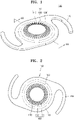
- FIG. 1 is a perspective view illustrating an adjustable intraocular lens 100 according to an embodiment of the present invention
- FIG. 2 is a plan view illustrating the adjustable intraocular lens 100 of FIG. 1
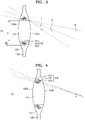
- FIG. 3 is a cross-sectional view taken along a line III-III of FIG. 1 .
- the adjustable intraocular lens 100 may include a lens body 150, an optical rod portion 160, and a support portion 170.
- the adjustable intraocular lens 100 may be implanted in a region from which all or part of a natural lens (17 in FIG. 10A ) of a human eye is removed.
- an incident angle of light incident on the adjustable intraocular lens 100 is defined as an angle between a direction of a center line CL in a thickness direction of the adjustable intraocular lens 100 and a direction of incident light. Therefore, that the incident angle is small means that light is almost vertically incident on the adjustable intraocular lens 100, and that the incident angle is large means that light is incident toward the adjustable intraocular lens 100 from the side of the adjustable intraocular lens 100.
- the lens body 150 may have a front surface 150a and a rear surface 150b.
- the front surface 150a corresponds to a region on which external light is incident.
- the rear surface 150b corresponds to the front surface 150a and corresponds to a region coming into contact with a human's lens capsule or facing a direction toward a human's retina. External light may enter the front surface 150a, move through the lens body 150, and pass through the rear surface 150b.
- the lens body 150 may include a central optic zone 110, a transition zone 120 in which the optical rod portion 160 is disposed, and an edge zone 130.
- the lens body 150 is a region through which external light transmits and is generally used as an optic.
- the lens body 150 may include a relatively hard material, a relatively soft, bendable semi-rigid material, or a combination of the hard material and the soft material.
- the lens body 150 may include polymethyl methacrylate (PMMA), polysulfone (PSF), or other relatively hard, biologically inert optical materials.
- the lens body 150 may include a silicone resin, hydrogel, thermolabile materials, and other flexible, semi-rigid, biologically inert optical materials.
- the central optic zone 110 may be convex in a first direction that is a thickness direction of the lens body 150.
- the front surface 150a of the central optic zone 110 may be convex in the first direction, or the rear surface 150b of the central optic zone 110 may be convex in the first direction.
- both the front surface 150a and the rear surface 150b may be convex.
- both the front surface 150a and the rear surface 150b are convex.
- the central optic zone 110 may be arranged at the center of the lens body 150.
- the central optic zone 110 can accommodate most of external light incident on the adjustable intraocular lens 100.
- the central optic zone 110 may be aligned with the macula when the adjustable intraocular lens 100 is implanted in the human eye.
- the transition zone 120 may surround the central optic zone 110, and the optical rod portion 160 may be arranged in the transition zone 120.
- the transition zone 120 may be formed such that the thickness of the transition zone 120 in the first direction decreases from the central optic zone 110 to the edge zone 130.
- a predetermined groove may be formed in the transition zone 120, so that the central optic zone 110 and the edge zone 130 may be distinguished from each other.
- the edge zone 130 may surround the transition zone 120, and a plurality of support portions 170 may be connected to the edge zone 130.
- the edge zone 130 may have a circular shape as illustrated in FIG. 2 .
- the shape of the edge zone 130 is not limited thereto, and a portion to which the support portion 170 is connected may be flat.
- the optical rod portion 160 may be arranged to surround the outer portion of the central optic zone 110.
- the optical rod portion 160 may be arranged such that at least some of the optical rod portion 160 is included inside the central optic zone 110.
- the optical rod portion 160 may extend in the first direction.
- the cross-section of the optical rod portion 160 may be polygonal or circular.
- the optical rod portion 160 may have a substantially polygonal column shape or a substantially circular column shape.
- a plurality of optical rod portions 160 may be arranged around the central optic zone 110 to form a ring shape. In addition, a plurality of the optical rod portions 160 may be arranged in a radial direction from the central optic zone 110. The optical rod portions 160 may be partially overlapped and continuously arranged to each other. In addition, the optical rod portions 160 may be arranged with a predetermined interval therebetween.
- a predetermined interval therebetween.
- the optical rod portion 160 may include a first rod portion 161 adjacent to the central optic zone 110 and arranged in a circular shape around the central optic zone 110, a second rod portion 162 arranged on the outside in the radial direction of the first rod portion 161, and a third rod portion 163 arranged on the outside in the radial direction of the second rod portion 162.
- the first rod portion 161, the second rod portion 162, and the third rod portion 163 may extend from the front surface 150a to the rear surface 150b, respectively.
- each optical rod portion 160 may have a predetermined angle with the first direction.
- the optical rod portion 160 may form a predetermined angle with the center line CL of the central optic zone 110.
- the angle may increase in proportion to the radial direction relative to the central optic zone 110.
- the optical rod portion 160 is arranged to have a predetermined angle so that, when light having a large incident angle is incident, the light can be reflected by a sidewall of the optical rod portion 160. At this time, the optical rod portion 160 has a slope and can increase the incidence area, thereby effectively aligning light.
- the longitudinal direction of the first rod portion 161 and the center line CL of the central optic zone 110 form a first angle ( ⁇ )
- the longitudinal direction of the second rod portion 162 and the center line CL of the central optic zone 110 form a second angle ( ⁇ )
- the longitudinal direction of the third rod portion 163 and the center line CL of the central optic zone 110 form a third angle ( ⁇ ).
- the third angle is greater than the second angle and greater than the first angle.
- the second angle is greater than the first angle.
- the optical rod portion 160 may be arranged so that the arrangement angle becomes smaller toward the radial direction from the center line CL.
- FIG. 4 is a cross-sectional view illustrating a modification of the adjustable intraocular lens 100 of FIG. 1 .
- a longitudinal center of an optical rod portion 160' may be formed in one region P.
- Longitudinal extension lines of the first rod portion 161', a second rod portion 162', and a third rod portion 163' may be arranged to be collected in one region P.
- the optical rod portion 160' may converge external light into one region to secure the field of view.
- a length b of a region in which the optical rod portion 160 is arranged may be less than a diameter a of the central optic zone 110.
- Most of light incident from the outside passes through the central optic zone 110, and only part of light having a large incident angle is reflected by the optical rod portion 160 to align the light.
- the incident angle is an angle between the first direction and the moving direction of the light. A detailed description thereof will be described below.
- a refractive index of the optical rod portion 160 may be different from a refractive index of the central optic zone 110.
- the refractive index of the optical rod portion 160 may be greater than the refractive index of the central optic zone 110, or the refractive index of the optical rod portion 160 may be less than the refractive index of the central optic zone 110.
- the light incident on the optical rod portion 160 may be selectively transmitted according to the incident angle.
- the optical rod portion 160 is selected from one of an optical fiber material and a glass fiber material.
- the support portion 170 may extend from the edge zone 130 of the lens body 150 in the radial direction.
- a plurality of support portions 170 may be provided, and the support portion 170 is typically used as a haptic.
- the support portion 170 can prevent the lens body 150 from moving or rotating within the eyeball. That is, the support portion 170 may be supported on the inner surface of the eye, such as being inserted inside the remnant lens capsule or being inserted in the sulcus between the ocular zonules and the iris , so that the lens body 150 may be arranged in the optical path of the eye.
- the support portion 170 may have various shapes and sizes according to a position at which the adjustable intraocular lens 100 is implanted. For example, the support portion 170 may have a C-shape, a J-shape, a U-shape, a flat design, or other designs.
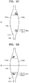
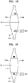
- FIGS. 5A to 5F are cross-sectional views illustrating another modification of the adjustable intraocular lens 100 of FIG. 1 .
- Modifications of the adjustable intraocular lens 100 are characteristically different in terms of the structure and arrangement of the optical rod portion which will be mainly described below
- an optical rod portion 160a may be inserted to connect a front surface 150a to a rear surface 150b.
- a first rod portion 161a and a second rod portion 162a may extend in the first direction from the front surface 150a toward the rear surface 150b.
- the optical rod portion 160a may partially pass external light incident on a transition zone 120 of the front surface 150a.
- the optical rod portion 160a may reflect part of incident light and may pass part of the incident light according to a refractive index of the optical rod portion 160a.
- the optical rod portion 160a may reflect the entire incident light.
- the optical rod portion 160a may pass the entire incident light.
- the optical rod portion 160a may pass only part of the external light incident on the adjustable intraocular lens 100 so that a clear image is formed on the retina.
- the optical rod portion 160a generates an effect similar to a pinhole effect, but the total amount of light passing through the optical rod portion 160a and the total area through which light passes are greatly increased, as compared to a conventional pinhole effect, so that a brighter and clearer image is generated on the retina.
- an optical rod portion 160b may be inserted into a front surface 150a.
- the optical rod portion 160b is inserted into the front surface 150a in the first direction at a predetermined length, and the optical rod portion 160b may not extend to a rear surface 150b.
- the optical rod portion 160b may include a first rod portion 161b and a second rod portion 162b, and may be inserted into the front surface 150a along the first direction at a predetermined length.
- the optical rod portion 160b may selectively pass part of external light incident on a transition zone 120 of the front surface 150a.
- the optical rod portion 160b may reflect part of incident light and may pass part of the incident light according to a refractive index of the optical rod portion 160b.
- the optical rod portion 160b may reflect the entire incident light.
- the optical rod portion 160b may pass the entire incident light.
- the optical rod portion 160b may pass only part of the external light incident on the adjustable intraocular lens 100 so that an image is clearly formed on a retina.
- the optical rod portion 160b generates an effect similar to a pinhole effect, but the total amount of light passing through the optical rod portion 160b and a total area through which light passes are greatly increased, as compared to a conventional pinhole effect, so that a brighter and clearer image is generated on the retina.
- an optical rod portion 160c may be inserted into a rear surface 150b.
- the optical rod portion 160c is inserted into the rear surface 150b along the first direction at a predetermined length, and the optical rod portion 160c may not extend to a front surface 150a.
- the optical rod portion 160c may include a first rod portion 161c and a second rod portion 162c, and may be inserted into the rear surface 150b along the first direction at a predetermined length.
- the optical rod portion 160c may selectively pass part of external light incident on a transition zone 120 of the front surface 150a.
- the external light is incident on the transition zone 120 and moves toward the optical rod portion 160c.
- the optical rod portion 160c may selectively pass part of external light incident on the transition zone 120 of the front surface 150a.
- the optical rod portion 160c may reflect part of incident light and may pass part of the incident light according to a refractive index of the optical rod portion 160c.
- the optical rod portion 160c may reflect the entire incident light.
- the optical rod portion 160c may pass the entire incident light.
- the optical rod portion 160c may pass only part of the external light incident on the adjustable intraocular lens 100 so that an image is clearly formed on a retina.
- the optical rod portion 160c generates an effect similar to a pinhole effect, but the total amount of light passing through the optical rod portion 160c and a total area through which light passes are greatly increased, as compared to a conventional pinhole effect, so that a brighter and clearer image is generated on the retina.
- an optical rod portion 160d is disposed inside a lens body 150.
- the optical rod portion 160d may be arranged adjacent to a front surface 150a of the lens body 150.
- the optical rod portion 160d may include a first rod portion 161d and a second rod portion 162d, each of which may be arranged within a transition zone 120 along the first direction. At this time, the first rod portion 161d and the second rod portion 162d may be arranged adjacent to the front surface 150a rather than a rear surface 150b.
- the optical rod portion 160d can selectively pass part of external light incident on the transition zone 120 of the front surface 150a.
- the optical rod portion 160d may reflect part of incident light and may pass part of the incident light according to a refractive index of the optical rod portion 160d.
- the optical rod portion 160d may reflect the entire incident light.
- the optical rod portion 160d may pass the entire incident light.
- the optical rod portion 160d may pass only part of the external light incident on the adjustable intraocular lens 100 so that an image is clearly formed on a retina.
- the optical rod portion 160d generates an effect similar to a pinhole effect, but the total amount of light passing through the optical rod portion 160d and a total area through which light passes are greatly increased, as compared to a conventional pinhole effect, so that a brighter and clearer image is generated on the retina.
- an optical rod portion 160e is arranged inside a lens body 150.
- the optical rod portion 160e may be arranged adjacent to a rear surface 150b of the lens body 150.
- the optical rod portion 160e may include a first rod portion 161e and a second rod portion 162e, each of which may be arranged within a transition zone 120 along the first direction. At this time, the first rod portion 161e and the second rod portion 162e may be arranged adjacent to the rear surface 150b rather than a front surface 150a.
- the optical rod portion 160e may selectively pass part of external light incident on the transition zone 120 of the front surface 150a.
- the optical rod portion 160e may reflect part of incident light and may pass part of the incident light according to a refractive index of the optical rod portion 160e.
- the optical rod portion 160e may reflect the entire incident light.
- the optical rod portion 160e may pass the entire incident light.
- the optical rod portion 160e may pass only part of the external light incident on the adjustable intraocular lens 100 so that an image is clearly formed on a retina.
- the optical rod portion 160e generates an effect similar to a pinhole effect, but the total amount of light passing through the optical rod portion 160e and a total area through which light passes are greatly increased, as compared to a conventional pinhole effect, so that a brighter and clearer image is generated on the retina.
- an optical rod portion 160f is arranged inside a lens body 150.
- the optical rod portion 160f may be arranged at the center of the thickness of the lens body 150.
- the optical rod portion 160f may include a first rod portion 161f and a second rod portion 162f, each of which may be arranged within a transition zone 120 along the first direction. At this time, the first rod portion 161f and the second rod portion 162f may be arranged between a front surface 150a and a rear surface 150b.
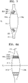
- FIG. 6 is a plan view illustrating an adjustable intraocular lens 200 according to another embodiment of the present invention
- FIG. 7 is a cross-sectional view taken along a line VII-VII of FIG. 6 .
- the adjustable intraocular lens 200 may include a lens body 250, a support portion 270, and an optical rod portion 260.
- the lens body 250 may include a central optic zone 210, a transition zone 220, and an edge zone 230.
- another embodiment of the present invention characteristically differs from the above-described embodiment in terms of the shape and arrangement of the optical rod portion 260. Therefore, in the description of the present invention, portions not described herein will quote the description of the above-mentioned embodiment, and the description thereof will not be explained in detail.
- a plurality of optical rod portions 260 may be arranged in a radial direction of a central optic zone 210, and diameters of the optical rod portions 260 may be reduced in the radial direction.
- diameters of the optical rod portions 260 may be reduced in the radial direction.
- the optical rod portion 260 may include a first rod portion 261 adjacent to the central optic zone 210 and arranged in a circular shape around the central optic zone 210, and a second rod portion 262 arranged on the outside in the radial direction of the first rod portion 261.
- the optical rod portion 260 may include a third rod portion 263 arranged on the outside in the radial direction of the second rod portion 262. The diameter of the first rod portion 261 arranged closest to the central optic zone 210 may be largest and the diameter of the third rod portion 263 arranged at the outermost portion of the central optic zone 210 may be smallest.
- a longitudinal direction of the optical rod portion 260 may have a predetermined angle with the first direction.
- the optical rod portion 260 may form a predetermined angle with a center line CL of the central optic zone 210.
- the angle may increase in the radial direction of the central optic zone 210.
- External light incident on the central optic zone 210 may pass through the central optic zone 210 to form an image on a retina.
- the light passing through the central optic zone 210 may adjust the formed image to be brighter.
- a plurality of optical rod portions 260 may be arranged in the radial direction of the central optic zone, and the diameters of the optical rod portions may be reduced in the radial direction.
- the diameter of the first rod portion 261 is designed to be large, the amount of aligned light toward the macula, which is a structure in the retina forming the center of a visual axis, may be further secured. Aligning the light may increase the depth of focus and by securing the maximum amount of aligned light, the adjustable intraocular lens 200 which projects a much brighter and clearer image on retina may be provided.
- the diameter of the third rod portion 263 is reduced, the density of optical rods included in the same area can be increased to effectively block the light which is incident at a larger incident angle toward the outside of the adjustable intraocular lens 200, the light disturbing improvement of the depth of focus.
- the adjustable intraocular lens 200 with improved brightness may be provided.
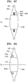
- FIGS. 8A to 8G are cross-sectional views illustrating modifications of the adjustable intraocular lens of FIG. 6 .
- Modifications of the adjustable intraocular lens 200 are characteristically different in terms of the structure and arrangement of the optical rod portion, and a description thereof will be described.
- an optical rod portion 260a may be inserted to connect a front surface 250a to a rear surface 250b.
- the optical rod portion 260a may include a first rod portion 261b, a second rod portion 262b, and a third rod portion 263c, each of which may extend from the front surface 250a to the rear surface 250b in the first direction.
- the diameter of the first rod portion 261a arranged closest to the central optic zone 210 may be largest and the diameter of the third rod portion 263c arranged at the outermost portion of the central optic zone 210 may be smallest.
- the optical rod portion 260b may be inserted into the front surface 250a.
- the optical rod portion 260b may be inserted into the front surface 250a along the first direction at a predetermined length, and the optical rod portion 260b may not extend to the rear surface 250b.
- the optical rod portion 260b may include a first rod portion 261b, a second rod portion 262b, and a third rod portion 263c, each of which may be inserted into the front surface 250a along the first direction.
- the diameter of the first rod portion 261b arranged closest to the central optic zone 210 may be largest and the diameter of the third rod portion 263b arranged at the outermost portion of the central optic zone 210 may be smallest.
- an optical rod portion 160c may be inserted into a rear surface 250b.
- the optical rod portion 260c may be inserted into the rear surface 250b along the first direction at a predetermined length, and the optical rod portion 260c may not extend to a front surface 250a.
- the optical rod portion 260c may include a first rod portion 261c, a second rod portion 262c, and a third rod portion 263c, each of which may be inserted into a rear surface 250b in the first direction.
- the diameter of the first rod portion 261c arranged closest to the central optic zone 210 may be largest and the diameter of the third rod portion 263c arranged at the outermost portion of the central optic zone 210 may be smallest.
- an optical rod portion 260d may be disposed inside a lens body 250.
- the optical rod portion 260d may be arranged adjacent to a front surface of the lens body 250.
- the optical rod portion 260d may include a first rod portion 261d, a second rod portion 262d, and a third rod portion 263d, each of which may be arranged within the transition zone 220 along the first direction.
- the first rod portion 261d, the second rod portion 262d, and the third rod portion 263d may be arranged adjacent to a front surface 250a rather than a rear surface 250b.
- the diameter of the first rod portion 261d arranged closest to a central optic zone 210 may be largest and the diameter of the third rod portion 263d arranged at the outermost portion of the central optic zone 210 may be smallest.
- an optical rod portion 260e may be arranged inside a lens body 250.
- the optical rod portion 260e may be arranged adjacent to a rear surface 250b of the lens body 250.
- the optical rod portion 260e may include a first rod portion 261e, a second rod portion 262e, and a third rod portion 263e, each of which may be arranged within the transition zone 220 in the first direction.
- the first rod portion 261e, the second rod portion 262e, and the third rod portion 263e may be arranged adjacent to a rear surface 250b rather than a front surface 250a.
- the diameter of the first rod portion 261e arranged closest to a central optic zone 210 may be largest and the diameter of the third rod portion 263e arranged at the outermost portion of the central optic zone 210 may be smallest.
- an optical rod portion 160f may be arranged inside a lens body 250.
- the optical rod portion 260f may be arranged at the center of the thickness of the lens body 250.
- the optical rod portion 260f may include a first rod portion 261f, a second rod portion 262f, and a third rod portion 263f, each of which may be arranged within the transition zone 220 in the first direction.
- the first rod portion 261f and the second rod portion 262f may be arranged between a front surface 250a and a rear surface 250b.
- FIG. 8G is a cross-sectional view illustrating another modification of the adjustable intraocular lens 200 of FIG. 6 .
- the modification of the adjustable intraocular lens 200 is characteristically different in terms of the structure and arrangement of the optical rod portion, and a description thereof will be described.
- An optical rod portion 260g may have a tapered outer wall 261g.
- the optical rod portion 260g may have the outer wall 261g tapered in the first direction. Specifically, a cross-section of the optical rod portion 260g is large on a front surface 250a and is reduced toward a rear surface 250b. Part of light incident on the optical rod portion 260g may strike the tapered outer wall 261g. That is, part of light passing through the optical rod portion 260g may strike the outer wall 261g again to reduce the amount of light transmitted through the optical rod portion 260g. Even if the volume of the optical rod portion 260g is reduced by the tapered outer wall 261g, the optical rod portion 260g may effectively reflect the incident light again and align the light.
- FIG. 9 is a perspective view illustrating an adjustable intraocular lens 300 according to another embodiment of the present invention.
- the adjustable intraocular lens 300 may include a lens body 350, a support portion 370, and an optical rod portion 360.
- the lens body 350 may include a central optic zone 310, a transition zone 220, and an edge zone 330.
- another embodiment of the present invention characteristically differs from the above-described embodiment in terms of the shape and arrangement of the optical rod portion 360. Therefore, in the description of the present invention, portions not described herein will quote the description of the above-mentioned embodiment, and the description thereof will not be explained in detail.
- the optical rod portion 360 may form a plurality of bands.
- the optical rod portion 360 may be arranged in the transition zone 320 and may be arranged with a predetermined interval in a radial direction.
- the number of bands including the optical rod portion 360 is not limited to a specific number. Hereinafter, for convenience of description, a case where three bands are formed will be described.
- the optical rod portion 360 may include a first rod band 361 arranged on an outer side of a central optic zone 310, a second rod band 362 arranged on an outer side of the first rod band 361, and a third rod band 363 arranged on an outside of the second rod band 362.
- the first rod band 361 and the second rod band 362 may be arranged with a predetermined interval
- the second rod band 362 and the third rod band 363 may be arranged with a predetermined interval.
- Each of the rod bands may have a predetermined angle with a center line CL of the lens body 350, or may contact with any one of the surfaces.
- each of the rod bands may be arranged adjacent to one side of the lens body 350 while having a gap therebetween, and may be arranged at the center of the lens body 350. The description thereof will quote the description of the above-mentioned embodiment.
- the adjustable intraocular lens 300 may increase the amount of light incident at intervals between the rod bands, thereby securing the field of view. That is, the field of view may be widened by external light passing through the gap between the rod bands.
- FIG. 10A is a cross-sectional view of a human eye 10 illustrating a natural lens
- FIG. 10B is a cross-sectional view of the human eye 10 into which an adjustable intraocular lens is inserted.
- FIG. 10A illustrates a cross-sectional view of the human eye 10 having a front chamber 12 and a rear chamber 14 that are separated by an iris 30.
- a lens capsule 16 holding a natural lens 17 of an eye is present in the rear chamber 14.
- Light entering the eye passes through a cornea 18 and travels to the lens 17, and the cornea 18 and the lens 17 serve to direct the light to an image on a retina 20 located at the back of the eye and adjust focus.
- the retina 20 is connected to an optic nerve 22, and the optic nerve 22 transfers the image received by the retina 20 to a brain for the purpose of analysis.
- the natural lens 17 can no longer properly focus or direct the incident light to the retina in a damaged eye 10 (for example, blurred by cataract), and the image is blurred.
- a well-known surgical technique for treating this condition includes removing the damaged lens and replacing the damaged lens with an artificial lens such as an intraocular lens.
- a surgeon may cut out all or part of the natural lens 17 and implant the adjustable intraocular lens 100.
- the central optic zone 110 may be aligned to be positioned to face the macula.
- the support portion 170 may be fixed at an appropriate position in the lens capsule so that the lens body 150 does not move.
- FIG. 11 is a conceptual diagram illustrating incidence of external light on the adjustable intraocular lens 100 of FIG. 1 .
- the adjustable intraocular lens 100 is implanted in the eye and the a clear image is generated on the retina
- a conventional multifocal intraocular lens When viewing an object from a medium or near distance, a conventional multifocal intraocular lens produces unfocused light, which causes flashes or halos, resulting in visual disturbance. This is related to the property of light that travels straight. Most of light incident from a long distance is vertically incident on the retina 20, but light incident from near distance has various incident angles and only part of the light is vertically incident on the retina 20. That is, when viewing an object at a medium or near distance, a plurality of images are formed on the retina due to light having different incident angles, resulting in visual disturbance.
- the adjustable intraocular lens 100 may form a clear image on the retina by aligning light incident at a near distance or a medium distance.
- D1 indicates light incident from a long distance
- D2 and D3 indicate light incident from a near distance or a medium distance
- D2 indicates light that passes through the optical rod portion 160
- D3 indicates light reflected from the sidewall of the optical rod portion 160 due to a large incident angle.
- Light incident from a long distance like D1 vertically enter the cornea 18, the central optic zone 110, or the optical rod portion 160 and pass therethrough. That is, most of the light incident from a long distance may pass through the adjustable intraocular lens 100.
- Light may pass through the optical rod portion 160 when light having a small incident angle is incident from a near distance or a medium distance like D2, that is, when light is incident almost perpendicular to the adjustable intraocular lens.
- Light having a small incident angle passes through both the central optic zone 110 and the optical rod portion 160, thereby improving the depth of focus.
- the optical rod portion 160 when light having a large incident angle is incident from a near distance or a medium distance like D3, light may be reflected by the optical rod portion 160. That is, when the incident angle of light directed to the adjustable intraocular lens 100 is large, the light directed toward the central optic zone 110 passes though the central optic zone 110, but the light directed toward the optical rod portion 160 is reflected because the refractive index of the optical rod portion 160 is different from that of the central optic zone 110.
- the light may be reflected from the side of the optical rod portion 160. Since the refractive index of the optical rod portion 160 is different from that of the transition zone 120, light having a large incident angle passes through the transition zone 120 and is reflected by a difference in refractive index at the side of the optical rod portion 160.
- a light absorbing coating or the like may be applied to the side surface of the optical rod portion 160.
- Light having a large incident angle may pass through the transition zone 120, or may be absorbed through the coating on the side surface of the optical rod portion 160.
- the adjustable intraocular lens 100 selectively passes only a part of incident light, thereby improving the depth of focus by aligning light in the optical rod portion 160. That is, the optical rod portion 160 generates an effect similar to the pinhole effect so that a clear image may be formed on the retina.
- the adjustable intraocular lens 100 transmits light incident on the central optic zone 110, but selectively transmits light incident on the optical rod portion 160, thereby forming a clear image.
- the adjustable intraocular lens 100 may align light by the optical rod portion 160 and minimize mutual interference of light, thereby improving the depth of focus.
- the adjustable intraocular lenses 200 and 300 may adjust the amount of light passing through the central optic zones 210 and 310, thereby adjusting the brightness of the image formed on the retina.
- an adjustable intraocular lens is provided to improve the depth of focus, and embodiments of the present invention are applicable to lenses, glasses, spectacles, and the like, to which the adjustable intraocular lens for industrial use is applied.
Landscapes
- Health & Medical Sciences (AREA)
- Ophthalmology & Optometry (AREA)
- Life Sciences & Earth Sciences (AREA)
- Animal Behavior & Ethology (AREA)
- Engineering & Computer Science (AREA)
- Biomedical Technology (AREA)
- Heart & Thoracic Surgery (AREA)
- Vascular Medicine (AREA)
- Veterinary Medicine (AREA)
- Public Health (AREA)
- General Health & Medical Sciences (AREA)
- Cardiology (AREA)
- Oral & Maxillofacial Surgery (AREA)
- Transplantation (AREA)
- Surgery (AREA)
- Nuclear Medicine, Radiotherapy & Molecular Imaging (AREA)
- Prostheses (AREA)
Description
- The present invention relates to an intraocular lens, and more particularly, an adjustable intraocular lens for implantation in a human eye.
- Generally, an intraocular lens (IOL) refers to an artificial lens that is implanted in an eye to replace an opaque lens of a cataract patient.
- Intraocular lens (artificial lens) insertion is a method of extracting a cataract from a patient and inserting an intraocular lens made of an artificial material into an eye as an alternative so as to replace the role of glasses or a contact lens after surgery. The intraocular lens insertion is currently implemented in many places around the world.
- A cataract is a disease in which the lens of the eye becomes opaque, the outside light cannot be clearly focused on the retina, and thus the visual acuity is reduced. In order to treat this disease, it is common to remove an opaque lens inside a lens capsule and perform an operation of inserting an intraocular lens made of various materials that do not cause complications such as inflammation when inserted into the eye.
- Research on the shape or material of an intraocular lens has continued with respect to implanting an intraocular lens so that a patient can clearly see a close or distant object. For example, there is a method of injecting a liquid, such as water, into an intraocular lens to perform a multifocal function or a method of changing a shape of an intraocular lens so as to adjust a focus.
-
U.S. Patent Publication No. 2009-0088840 (entitled ZONAL DIFFRACTIVE MULTIFOCAL INTRAOCULAR LENSES) discloses a technique for forming a refractive region on a surface of a lens so as to provide a multifocal intraocular lens. - U.S. patent application publishes as
US 2004/0184158 A1 discloses intraocular lenses (IOL) for correcting human vision. The IOL carries an interior phase or layer comprising a pattern of individual transparent adaptive displacement structures. In an embodiment, the displacement structures are actuated by shape change polymer that adjusts a shape or other parameter in response to applied energy that in turn displaces a fluid media within the lens that actuates a flexible lens surface. The adaptive optic means can be used to create highly localized surface corrections in the lens to correct higher order aberrations, which types of surfaces cannot be fabricated into and IOL and then implanted. The system of displacement structures also can provide spherical corrections in the lens. - Embodiments of the present invention provide adjustable intraocular lenses that align light incident on an intraocular lens so as to improve visibility.
- In view of the technical problem, the claimed invention provides an intraocular lens comprising the features of
claim 1. - The adjustable intraocular lens comprises a lens body having a front surface and a rear surface and comprising a central optic zone formed convexly in a first direction, and an optical rod portion comprising optical rods, said optical rod portion arranged so that at least part thereof is included inside the central optic zone and the optical rod portion surrounds an outer portion of the central optic zone. The optical rod portion is arranged inside the lens body. The optical rods are at least one of glass rods and optical fibers. A refractive index of the optical rod portion is different from a refractive index of the central optic zone, such that external light directed to the central optic zone passes through the central optic zone and external light directed to the optical rod portion selectively passes through the optical rod portion depending on an incident angle, which is defined as an angle between a direction of a center line in a thickness direction of the adjustable intraocular lens and a direction of the incident light.
- A plurality of support portions extending from an edge of the lens body in a radial direction may be provided. An optical rod portion is arranged so that at least part thereof is included inside the central optic zone and the optical rod portion surrounds an outer portion of the central optic zone.
- An intraocular lens according to the present invention may transmit light incident on a central optic zone, but selectively transmit light incident on an optical rod portion, thereby forming a clearer image. The optical rod portion may align incident light, thereby improving the depth of focus. In addition, the intraocular lens may adjust the amount of light passing through the central optic zone, thereby adjusting the brightness of an image formed on a retina. The scope of the present invention is not limited by such effects. The intraocular lens may be denoted as adjustable intraocular lens as the optical properties may be adjusted by using different optical rods.
-
-
FIG. 1 is a perspective view illustrating an adjustable intraocular lens according to an embodiment of the present invention. -
FIG. 2 is a plan view illustrating the adjustable intraocular lens ofFIG. 1 . -
FIG. 3 is a cross-sectional view taken along a line III-III ofFIG. 1 . -
FIG. 4 is a cross-sectional view illustrating a modification of the adjustable intraocular lens ofFIG. 1 . -
FIGS. 5A to 5F are cross-sectional views illustrating another modification of the adjustable intraocular lens ofFIG. 1 . -
FIG. 6 is a plan view illustrating an adjustable intraocular lens according to another embodiment of the present invention. -
FIG. 7 is a cross-sectional view taken along a line VII-VII ofFIG. 6 . -
FIGS. 8A to 8G are cross-sectional views illustrating modifications of the adjustable intraocular lens ofFIG. 6 . -
FIG. 9 is a plan view illustrating an adjustable intraocular lens according to another embodiment of the present invention. -
FIG. 10A is a cross-sectional view of a human eye illustrating a natural lens. -
FIG. 10B is a cross-sectional view of a human eye into which an adjustable intraocular lens is inserted. -
FIG. 11 is a conceptual diagram illustrating incidence of external light on the adjustable intraocular lens ofFIG. 1 . - An aspect of the present invention provides an adjustable (accommodative) intraocular lens including: a lens body having a front surface and a rear surface and including a central optic zone formed convexly in a first direction; a plurality of support portions extending from an edge of the lens body in a radial direction; and an optical rod portion arranged so that at least part thereof is included inside the central optic zone and the optical rod portion surrounds an outer portion of the central optic zone.
- A refractive index of the optical rod portion may be different from a refractive index of the central optic zone.
- The optical rod portion may be arranged so that a length direction of the optical rod portion and the first direction form a predetermined angle.
- The lens body may include: a transition zone which surrounds the central optic zone and in which the optical rod portion is arranged; and an edge zone which surrounds the transition zone and to which the plurality of support portions are connected.
- A thickness of the transition zone in the first direction may be gradually reduced from the central optic zone toward the edge zone.
- The optical rod portion may include: a first rod portion arranged adjacent to the central optic zone; and a second rod portion arranged adjacent to the first rod portion in a radial direction.
- An angle formed by the length direction of the first rod portion and the first direction may be less than an angle formed by a length direction of the second rod portion and the first direction.
- A plurality of optical rod portions may be arranged in a radial direction of the central optic zone, and diameters of the optical rod portions may be reduced in the radial direction.
- The optical rod portion may extend from the front surface to the rear surface of the lens body.
- The optical rod portion may be inserted into the front surface or the rear surface of the lens body.
- The optical rod portion may be arranged inside the lens body.
- The optical rod portion may be arranged adjacent to the front surface rather than the rear surface of the lens body, or may be arranged adjacent to the rear surface rather than the front surface of the lens body.
- An outer wall of the optical rod portion may be tapered in the first direction.
- The optical rod portion includes at least one of a glass rod or an optical fiber.
- At least some of external light incident on the optical rod portion may be totally reflected from an inner wall of the optical rod portion. External light directed toward the central optic zone may pass through the central optic zone, and the external light directed toward the optical rod portion may selectively pass through the optical rod portion according to an incident angle.
- A light absorbing coating may be applied to an outer wall of the optical rod portion.
- Embodiments will now be described more fully hereinafter with reference to the accompanying drawings; however, they may be embodied in different forms and should not be construed as limited to the embodiments set forth herein. Rather, these embodiments are provided so that this disclosure will be thorough and complete, and will fully convey exemplary implementations to those skilled in the art. The scope of the present invention is defined by the appended claims. The terminology used herein is for the purpose of describing particular embodiments only, and is not intended to be limiting. An expression used in the singular encompasses the expression in the plural, unless it has a clearly different meaning in the context. It will be understood that the terms "comprises," "includes," "including," and/or "comprising," when used in this specification, specify the presence of stated components, steps, operations, and/or elements, but do not preclude the presence or addition of one or more other components, steps, operations, and/or elements. While the terms as "first," "second,", and the like, may be used to describe various components, such components must not be limited to the above terms. The above terms are used only to distinguish one component from another.
-
FIG. 1 is a perspective view illustrating an adjustableintraocular lens 100 according to an embodiment of the present invention,FIG. 2 is a plan view illustrating the adjustableintraocular lens 100 ofFIG. 1 , andFIG. 3 is a cross-sectional view taken along a line III-III ofFIG. 1 . - Referring to
FIGS. 1 to 3 , the adjustableintraocular lens 100 may include alens body 150, anoptical rod portion 160, and asupport portion 170. The adjustableintraocular lens 100 may be implanted in a region from which all or part of a natural lens (17 inFIG. 10A ) of a human eye is removed. - Hereinafter, an incident angle of light incident on the adjustable
intraocular lens 100 is defined as an angle between a direction of a center line CL in a thickness direction of the adjustableintraocular lens 100 and a direction of incident light. Therefore, that the incident angle is small means that light is almost vertically incident on the adjustableintraocular lens 100, and that the incident angle is large means that light is incident toward the adjustableintraocular lens 100 from the side of the adjustableintraocular lens 100. - The
lens body 150 may have afront surface 150a and arear surface 150b. Thefront surface 150a corresponds to a region on which external light is incident. Therear surface 150b corresponds to thefront surface 150a and corresponds to a region coming into contact with a human's lens capsule or facing a direction toward a human's retina. External light may enter thefront surface 150a, move through thelens body 150, and pass through therear surface 150b. - The
lens body 150 may include acentral optic zone 110, atransition zone 120 in which theoptical rod portion 160 is disposed, and anedge zone 130. Thelens body 150 is a region through which external light transmits and is generally used as an optic. - The
lens body 150 may include a relatively hard material, a relatively soft, bendable semi-rigid material, or a combination of the hard material and the soft material. For example, thelens body 150 may include polymethyl methacrylate (PMMA), polysulfone (PSF), or other relatively hard, biologically inert optical materials. In addition, thelens body 150 may include a silicone resin, hydrogel, thermolabile materials, and other flexible, semi-rigid, biologically inert optical materials. - The
central optic zone 110 may be convex in a first direction that is a thickness direction of thelens body 150. Thefront surface 150a of thecentral optic zone 110 may be convex in the first direction, or therear surface 150b of thecentral optic zone 110 may be convex in the first direction. In addition, as illustrated inFIG. 3 , both thefront surface 150a and therear surface 150b may be convex. Hereinafter, for convenience of description, a case where both thefront surface 150a and therear surface 150b are convex will be described. - The
central optic zone 110 may be arranged at the center of thelens body 150. Thecentral optic zone 110 can accommodate most of external light incident on the adjustableintraocular lens 100. Thecentral optic zone 110 may be aligned with the macula when the adjustableintraocular lens 100 is implanted in the human eye. - The
transition zone 120 may surround thecentral optic zone 110, and theoptical rod portion 160 may be arranged in thetransition zone 120. Thetransition zone 120 may be formed such that the thickness of thetransition zone 120 in the first direction decreases from thecentral optic zone 110 to theedge zone 130. In addition, a predetermined groove may be formed in thetransition zone 120, so that thecentral optic zone 110 and theedge zone 130 may be distinguished from each other. - The
edge zone 130 may surround thetransition zone 120, and a plurality ofsupport portions 170 may be connected to theedge zone 130. Theedge zone 130 may have a circular shape as illustrated inFIG. 2 . However, the shape of theedge zone 130 is not limited thereto, and a portion to which thesupport portion 170 is connected may be flat. - The
optical rod portion 160 may be arranged to surround the outer portion of thecentral optic zone 110. Theoptical rod portion 160 may be arranged such that at least some of theoptical rod portion 160 is included inside thecentral optic zone 110. Theoptical rod portion 160 may extend in the first direction. In addition, the cross-section of theoptical rod portion 160 may be polygonal or circular. For example, theoptical rod portion 160 may have a substantially polygonal column shape or a substantially circular column shape. - A plurality of
optical rod portions 160 may be arranged around thecentral optic zone 110 to form a ring shape. In addition, a plurality of theoptical rod portions 160 may be arranged in a radial direction from thecentral optic zone 110. Theoptical rod portions 160 may be partially overlapped and continuously arranged to each other. In addition, theoptical rod portions 160 may be arranged with a predetermined interval therebetween. Hereinafter, for convenience of description, a case where threeoptical rod portions 160 are regularly arranged with a predetermined interval will be described. - Specifically, the
optical rod portion 160 may include afirst rod portion 161 adjacent to thecentral optic zone 110 and arranged in a circular shape around thecentral optic zone 110, asecond rod portion 162 arranged on the outside in the radial direction of thefirst rod portion 161, and athird rod portion 163 arranged on the outside in the radial direction of thesecond rod portion 162. - The
first rod portion 161, thesecond rod portion 162, and thethird rod portion 163 may extend from thefront surface 150a to therear surface 150b, respectively. - A longitudinal direction of each
optical rod portion 160 may have a predetermined angle with the first direction. Theoptical rod portion 160 may form a predetermined angle with the center line CL of thecentral optic zone 110. In addition, the angle may increase in proportion to the radial direction relative to thecentral optic zone 110. Theoptical rod portion 160 is arranged to have a predetermined angle so that, when light having a large incident angle is incident, the light can be reflected by a sidewall of theoptical rod portion 160. At this time, theoptical rod portion 160 has a slope and can increase the incidence area, thereby effectively aligning light. - Specifically, the longitudinal direction of the
first rod portion 161 and the center line CL of thecentral optic zone 110 form a first angle (α), the longitudinal direction of thesecond rod portion 162 and the center line CL of thecentral optic zone 110 form a second angle (β), and the longitudinal direction of thethird rod portion 163 and the center line CL of thecentral optic zone 110 form a third angle (γ). The third angle is greater than the second angle and greater than the first angle. In addition, the second angle is greater than the first angle. Furthermore, theoptical rod portion 160 may be arranged so that the arrangement angle becomes smaller toward the radial direction from the center line CL. -
FIG. 4 is a cross-sectional view illustrating a modification of the adjustableintraocular lens 100 ofFIG. 1 . - Referring to
FIG. 4 , a longitudinal center of an optical rod portion 160' may be formed in one region P. Longitudinal extension lines of the first rod portion 161', a second rod portion 162', and a third rod portion 163' may be arranged to be collected in one region P. The optical rod portion 160' may converge external light into one region to secure the field of view. - Referring to
FIG. 3 again, a length b of a region in which theoptical rod portion 160 is arranged may be less than a diameter a of thecentral optic zone 110. Most of light incident from the outside passes through thecentral optic zone 110, and only part of light having a large incident angle is reflected by theoptical rod portion 160 to align the light. Hereinafter, the incident angle is an angle between the first direction and the moving direction of the light. A detailed description thereof will be described below. - A refractive index of the
optical rod portion 160 may be different from a refractive index of thecentral optic zone 110. For example, the refractive index of theoptical rod portion 160 may be greater than the refractive index of thecentral optic zone 110, or the refractive index of theoptical rod portion 160 may be less than the refractive index of thecentral optic zone 110. Thus, the light incident on theoptical rod portion 160 may be selectively transmitted according to the incident angle. According to the invention, theoptical rod portion 160 is selected from one of an optical fiber material and a glass fiber material. - The
support portion 170 may extend from theedge zone 130 of thelens body 150 in the radial direction. A plurality ofsupport portions 170 may be provided, and thesupport portion 170 is typically used as a haptic. - The
support portion 170 can prevent thelens body 150 from moving or rotating within the eyeball. That is, thesupport portion 170 may be supported on the inner surface of the eye, such as being inserted inside the remnant lens capsule or being inserted in the sulcus between the ocular zonules and the iris , so that thelens body 150 may be arranged in the optical path of the eye. Thesupport portion 170 may have various shapes and sizes according to a position at which the adjustableintraocular lens 100 is implanted. For example, thesupport portion 170 may have a C-shape, a J-shape, a U-shape, a flat design, or other designs. Hereinafter, for convenience of description, a case where twosupport portions 170 extend from theedge zone 130 will be described.FIGS. 5A to 5F are cross-sectional views illustrating another modification of the adjustableintraocular lens 100 ofFIG. 1 . Modifications of the adjustableintraocular lens 100 are characteristically different in terms of the structure and arrangement of the optical rod portion which will be mainly described below - Referring to
FIG. 5A , an optical rod portion 160a may be inserted to connect afront surface 150a to arear surface 150b. A first rod portion 161a and asecond rod portion 162a may extend in the first direction from thefront surface 150a toward therear surface 150b. - The optical rod portion 160a may partially pass external light incident on a
transition zone 120 of thefront surface 150a. The optical rod portion 160a may reflect part of incident light and may pass part of the incident light according to a refractive index of the optical rod portion 160a. In addition, when an incident angle of the external light is equal to or greater than a critical angle of the optical rod portion 160a, the optical rod portion 160a may reflect the entire incident light. In addition, when the incident angle of the external light falls within a predetermined range, the optical rod portion 160a may pass the entire incident light. The optical rod portion 160a may pass only part of the external light incident on the adjustableintraocular lens 100 so that a clear image is formed on the retina. The optical rod portion 160a generates an effect similar to a pinhole effect, but the total amount of light passing through the optical rod portion 160a and the total area through which light passes are greatly increased, as compared to a conventional pinhole effect, so that a brighter and clearer image is generated on the retina. - Referring to
FIG. 5B , anoptical rod portion 160b may be inserted into afront surface 150a. Theoptical rod portion 160b is inserted into thefront surface 150a in the first direction at a predetermined length, and theoptical rod portion 160b may not extend to arear surface 150b. - For example, the
optical rod portion 160b may include afirst rod portion 161b and asecond rod portion 162b, and may be inserted into thefront surface 150a along the first direction at a predetermined length. - The
optical rod portion 160b may selectively pass part of external light incident on atransition zone 120 of thefront surface 150a. Theoptical rod portion 160b may reflect part of incident light and may pass part of the incident light according to a refractive index of theoptical rod portion 160b. In addition, when an incident angle of the external light is equal to or greater than a critical angle of theoptical rod portion 160b, theoptical rod portion 160b may reflect the entire incident light. In addition, when the incident angle of the external light falls within a predetermined range, theoptical rod portion 160b may pass the entire incident light. Theoptical rod portion 160b may pass only part of the external light incident on the adjustableintraocular lens 100 so that an image is clearly formed on a retina. Theoptical rod portion 160b generates an effect similar to a pinhole effect, but the total amount of light passing through theoptical rod portion 160b and a total area through which light passes are greatly increased, as compared to a conventional pinhole effect, so that a brighter and clearer image is generated on the retina. - Referring to
FIG. 5C , anoptical rod portion 160c may be inserted into arear surface 150b. Theoptical rod portion 160c is inserted into therear surface 150b along the first direction at a predetermined length, and theoptical rod portion 160c may not extend to afront surface 150a. - For example, the
optical rod portion 160c may include afirst rod portion 161c and asecond rod portion 162c, and may be inserted into therear surface 150b along the first direction at a predetermined length. - The
optical rod portion 160c may selectively pass part of external light incident on atransition zone 120 of thefront surface 150a. The external light is incident on thetransition zone 120 and moves toward theoptical rod portion 160c. - The
optical rod portion 160c may selectively pass part of external light incident on thetransition zone 120 of thefront surface 150a. Theoptical rod portion 160c may reflect part of incident light and may pass part of the incident light according to a refractive index of theoptical rod portion 160c. In addition, when an incident angle of the external light is equal to or greater than a critical angle of theoptical rod portion 160c, theoptical rod portion 160c may reflect the entire incident light. In addition, when the incident angle of the external light falls within a predetermined range, theoptical rod portion 160c may pass the entire incident light. Theoptical rod portion 160c may pass only part of the external light incident on the adjustableintraocular lens 100 so that an image is clearly formed on a retina. Theoptical rod portion 160c generates an effect similar to a pinhole effect, but the total amount of light passing through theoptical rod portion 160c and a total area through which light passes are greatly increased, as compared to a conventional pinhole effect, so that a brighter and clearer image is generated on the retina. - Referring to
FIG. 5D , anoptical rod portion 160d is disposed inside alens body 150. Theoptical rod portion 160d may be arranged adjacent to afront surface 150a of thelens body 150. - For example, the
optical rod portion 160d may include afirst rod portion 161d and asecond rod portion 162d, each of which may be arranged within atransition zone 120 along the first direction. At this time, thefirst rod portion 161d and thesecond rod portion 162d may be arranged adjacent to thefront surface 150a rather than arear surface 150b. - The
optical rod portion 160d can selectively pass part of external light incident on thetransition zone 120 of thefront surface 150a. Theoptical rod portion 160d may reflect part of incident light and may pass part of the incident light according to a refractive index of theoptical rod portion 160d. In addition, when an incident angle of the external light is equal to or greater than a critical angle of theoptical rod portion 160d, theoptical rod portion 160d may reflect the entire incident light. In addition, when the incident angle of the external light falls within a predetermined range, theoptical rod portion 160d may pass the entire incident light. - The
optical rod portion 160d may pass only part of the external light incident on the adjustableintraocular lens 100 so that an image is clearly formed on a retina. Theoptical rod portion 160d generates an effect similar to a pinhole effect, but the total amount of light passing through theoptical rod portion 160d and a total area through which light passes are greatly increased, as compared to a conventional pinhole effect, so that a brighter and clearer image is generated on the retina. - Referring to
FIG. 5E , an optical rod portion 160e is arranged inside alens body 150. The optical rod portion 160e may be arranged adjacent to arear surface 150b of thelens body 150. - For example, the optical rod portion 160e may include a first rod portion 161e and a
second rod portion 162e, each of which may be arranged within atransition zone 120 along the first direction. At this time, the first rod portion 161e and thesecond rod portion 162e may be arranged adjacent to therear surface 150b rather than afront surface 150a. - The optical rod portion 160e may selectively pass part of external light incident on the
transition zone 120 of thefront surface 150a. The optical rod portion 160e may reflect part of incident light and may pass part of the incident light according to a refractive index of the optical rod portion 160e. In addition, when an incident angle of the external light is equal to or greater than a critical angle of the optical rod portion 160e, the optical rod portion 160e may reflect the entire incident light. In addition, when the incident angle of the external light falls within a predetermined range, the optical rod portion 160e may pass the entire incident light. The optical rod portion 160e may pass only part of the external light incident on the adjustableintraocular lens 100 so that an image is clearly formed on a retina. The optical rod portion 160e generates an effect similar to a pinhole effect, but the total amount of light passing through the optical rod portion 160e and a total area through which light passes are greatly increased, as compared to a conventional pinhole effect, so that a brighter and clearer image is generated on the retina. - Referring to
FIG. 5F , anoptical rod portion 160f is arranged inside alens body 150. Theoptical rod portion 160f may be arranged at the center of the thickness of thelens body 150. - For example, the
optical rod portion 160f may include afirst rod portion 161f and asecond rod portion 162f, each of which may be arranged within atransition zone 120 along the first direction. At this time, thefirst rod portion 161f and thesecond rod portion 162f may be arranged between afront surface 150a and arear surface 150b. -
FIG. 6 is a plan view illustrating an adjustableintraocular lens 200 according to another embodiment of the present invention, andFIG. 7 is a cross-sectional view taken along a line VII-VII ofFIG. 6 . - Referring to
FIGS. 6 to 7 , the adjustableintraocular lens 200 may include alens body 250, asupport portion 270, and anoptical rod portion 260. Thelens body 250 may include acentral optic zone 210, atransition zone 220, and anedge zone 230. However, another embodiment of the present invention characteristically differs from the above-described embodiment in terms of the shape and arrangement of theoptical rod portion 260. Therefore, in the description of the present invention, portions not described herein will quote the description of the above-mentioned embodiment, and the description thereof will not be explained in detail. - A plurality of
optical rod portions 260 may be arranged in a radial direction of acentral optic zone 210, and diameters of theoptical rod portions 260 may be reduced in the radial direction. Hereinafter, for convenience of description, a case where three rod portions are formed will be described. - Specifically, the
optical rod portion 260 may include afirst rod portion 261 adjacent to thecentral optic zone 210 and arranged in a circular shape around thecentral optic zone 210, and asecond rod portion 262 arranged on the outside in the radial direction of thefirst rod portion 261. In addition, theoptical rod portion 260 may include athird rod portion 263 arranged on the outside in the radial direction of thesecond rod portion 262. The diameter of thefirst rod portion 261 arranged closest to thecentral optic zone 210 may be largest and the diameter of thethird rod portion 263 arranged at the outermost portion of thecentral optic zone 210 may be smallest. - A longitudinal direction of the
optical rod portion 260 may have a predetermined angle with the first direction. Theoptical rod portion 260 may form a predetermined angle with a center line CL of thecentral optic zone 210. In addition, the angle may increase in the radial direction of thecentral optic zone 210. External light incident on thecentral optic zone 210 may pass through thecentral optic zone 210 to form an image on a retina. In addition, the light passing through thecentral optic zone 210 may adjust the formed image to be brighter. - A plurality of
optical rod portions 260 may be arranged in the radial direction of the central optic zone, and the diameters of the optical rod portions may be reduced in the radial direction. When the diameter of thefirst rod portion 261 is designed to be large, the amount of aligned light toward the macula, which is a structure in the retina forming the center of a visual axis, may be further secured. Aligning the light may increase the depth of focus and by securing the maximum amount of aligned light, the adjustableintraocular lens 200 which projects a much brighter and clearer image on retina may be provided. When the diameter of thethird rod portion 263 is reduced, the density of optical rods included in the same area can be increased to effectively block the light which is incident at a larger incident angle toward the outside of the adjustableintraocular lens 200, the light disturbing improvement of the depth of focus. - In another embodiment, when the diameter of the
first rod portion 261 is reduced, the area occupied by thefirst rod portion 261 in thetransition zone 220 is reduced. Therefore, light incident on thetransition zone 220 is relatively increased. Since thefirst rod portion 261 is arranged adjacent to thecentral optic zone 210, the amount of light incident on a region near thecentral optic zone 210 may be increased and the amount of light incident on a region farther from thecentral optic zone 210 may be reduced. Thus, the adjustableintraocular lens 200 with improved brightness may be provided. -
FIGS. 8A to 8G are cross-sectional views illustrating modifications of the adjustable intraocular lens ofFIG. 6 . Modifications of the adjustableintraocular lens 200 are characteristically different in terms of the structure and arrangement of the optical rod portion, and a description thereof will be described. - Referring to
FIG. 8A , anoptical rod portion 260a may be inserted to connect afront surface 250a to arear surface 250b. For example, theoptical rod portion 260a may include afirst rod portion 261b, asecond rod portion 262b, and athird rod portion 263c, each of which may extend from thefront surface 250a to therear surface 250b in the first direction. The diameter of thefirst rod portion 261a arranged closest to thecentral optic zone 210 may be largest and the diameter of thethird rod portion 263c arranged at the outermost portion of thecentral optic zone 210 may be smallest. - Referring to
FIG. 8B , theoptical rod portion 260b may be inserted into thefront surface 250a. Theoptical rod portion 260b may be inserted into thefront surface 250a along the first direction at a predetermined length, and theoptical rod portion 260b may not extend to therear surface 250b. - For example, the
optical rod portion 260b may include afirst rod portion 261b, asecond rod portion 262b, and athird rod portion 263c, each of which may be inserted into thefront surface 250a along the first direction. The diameter of thefirst rod portion 261b arranged closest to thecentral optic zone 210 may be largest and the diameter of thethird rod portion 263b arranged at the outermost portion of thecentral optic zone 210 may be smallest. - Referring to
FIG. 8C , anoptical rod portion 160c may be inserted into arear surface 250b. The optical rod portion 260c may be inserted into therear surface 250b along the first direction at a predetermined length, and the optical rod portion 260c may not extend to afront surface 250a. - For example, the optical rod portion 260c may include a
first rod portion 261c, a second rod portion 262c, and athird rod portion 263c, each of which may be inserted into arear surface 250b in the first direction. The diameter of thefirst rod portion 261c arranged closest to thecentral optic zone 210 may be largest and the diameter of thethird rod portion 263c arranged at the outermost portion of thecentral optic zone 210 may be smallest. - Referring to
FIG. 8D , anoptical rod portion 260d may be disposed inside alens body 250. Theoptical rod portion 260d may be arranged adjacent to a front surface of thelens body 250. - For example, the
optical rod portion 260d may include afirst rod portion 261d, asecond rod portion 262d, and athird rod portion 263d, each of which may be arranged within thetransition zone 220 along the first direction. At this time, thefirst rod portion 261d, thesecond rod portion 262d, and thethird rod portion 263d may be arranged adjacent to afront surface 250a rather than arear surface 250b. - In addition, the diameter of the
first rod portion 261d arranged closest to acentral optic zone 210 may be largest and the diameter of thethird rod portion 263d arranged at the outermost portion of thecentral optic zone 210 may be smallest. - Referring to
FIG. 8E , an optical rod portion 260e may be arranged inside alens body 250. The optical rod portion 260e may be arranged adjacent to arear surface 250b of thelens body 250. - For example, the optical rod portion 260e may include a
first rod portion 261e, a second rod portion 262e, and athird rod portion 263e, each of which may be arranged within thetransition zone 220 in the first direction. At this time, thefirst rod portion 261e, the second rod portion 262e, and thethird rod portion 263e may be arranged adjacent to arear surface 250b rather than afront surface 250a. - In addition, the diameter of the
first rod portion 261e arranged closest to acentral optic zone 210 may be largest and the diameter of thethird rod portion 263e arranged at the outermost portion of thecentral optic zone 210 may be smallest. - Referring to
FIG. 8F , anoptical rod portion 160f may be arranged inside alens body 250. Theoptical rod portion 260f may be arranged at the center of the thickness of thelens body 250. - For example, the
optical rod portion 260f may include afirst rod portion 261f, asecond rod portion 262f, and athird rod portion 263f, each of which may be arranged within thetransition zone 220 in the first direction. At this time, thefirst rod portion 261f and thesecond rod portion 262f may be arranged between afront surface 250a and arear surface 250b. -
FIG. 8G is a cross-sectional view illustrating another modification of the adjustableintraocular lens 200 ofFIG. 6 . The modification of the adjustableintraocular lens 200 is characteristically different in terms of the structure and arrangement of the optical rod portion, and a description thereof will be described. - An optical rod portion 260g may have a tapered
outer wall 261g. The optical rod portion 260g may have theouter wall 261g tapered in the first direction. Specifically, a cross-section of the optical rod portion 260g is large on afront surface 250a and is reduced toward arear surface 250b. Part of light incident on the optical rod portion 260g may strike the taperedouter wall 261g. That is, part of light passing through the optical rod portion 260g may strike theouter wall 261g again to reduce the amount of light transmitted through the optical rod portion 260g. Even if the volume of the optical rod portion 260g is reduced by the taperedouter wall 261g, the optical rod portion 260g may effectively reflect the incident light again and align the light. -
FIG. 9 is a perspective view illustrating an adjustableintraocular lens 300 according to another embodiment of the present invention. - Referring to
FIG. 9 , the adjustableintraocular lens 300 may include alens body 350, asupport portion 370, and anoptical rod portion 360. Thelens body 350 may include acentral optic zone 310, atransition zone 220, and anedge zone 330. However, another embodiment of the present invention characteristically differs from the above-described embodiment in terms of the shape and arrangement of theoptical rod portion 360. Therefore, in the description of the present invention, portions not described herein will quote the description of the above-mentioned embodiment, and the description thereof will not be explained in detail. - The
optical rod portion 360 may form a plurality of bands. Theoptical rod portion 360 may be arranged in thetransition zone 320 and may be arranged with a predetermined interval in a radial direction. The number of bands including theoptical rod portion 360 is not limited to a specific number. Hereinafter, for convenience of description, a case where three bands are formed will be described. - Specifically, the
optical rod portion 360 may include afirst rod band 361 arranged on an outer side of acentral optic zone 310, asecond rod band 362 arranged on an outer side of thefirst rod band 361, and athird rod band 363 arranged on an outside of thesecond rod band 362. Thefirst rod band 361 and thesecond rod band 362 may be arranged with a predetermined interval, and thesecond rod band 362 and thethird rod band 363 may be arranged with a predetermined interval. Each of the rod bands may have a predetermined angle with a center line CL of thelens body 350, or may contact with any one of the surfaces. In addition, each of the rod bands may be arranged adjacent to one side of thelens body 350 while having a gap therebetween, and may be arranged at the center of thelens body 350. The description thereof will quote the description of the above-mentioned embodiment. - The adjustable
intraocular lens 300 may increase the amount of light incident at intervals between the rod bands, thereby securing the field of view. That is, the field of view may be widened by external light passing through the gap between the rod bands. -
FIG. 10A is a cross-sectional view of ahuman eye 10 illustrating a natural lens, andFIG. 10B is a cross-sectional view of thehuman eye 10 into which an adjustable intraocular lens is inserted. -
FIG. 10A illustrates a cross-sectional view of thehuman eye 10 having afront chamber 12 and arear chamber 14 that are separated by aniris 30. In therear chamber 14, alens capsule 16 holding anatural lens 17 of an eye is present. Light entering the eye passes through acornea 18 and travels to thelens 17, and thecornea 18 and thelens 17 serve to direct the light to an image on aretina 20 located at the back of the eye and adjust focus. Theretina 20 is connected to anoptic nerve 22, and theoptic nerve 22 transfers the image received by theretina 20 to a brain for the purpose of analysis. - The
natural lens 17 can no longer properly focus or direct the incident light to the retina in a damaged eye 10 (for example, blurred by cataract), and the image is blurred. A well-known surgical technique for treating this condition includes removing the damaged lens and replacing the damaged lens with an artificial lens such as an intraocular lens. - Referring to
FIG. 10B , a surgeon may cut out all or part of thenatural lens 17 and implant the adjustableintraocular lens 100. At this time, thecentral optic zone 110 may be aligned to be positioned to face the macula. Thesupport portion 170 may be fixed at an appropriate position in the lens capsule so that thelens body 150 does not move. -
FIG. 11 is a conceptual diagram illustrating incidence of external light on the adjustableintraocular lens 100 ofFIG. 1 . - Referring to
FIG. 11 , it can be seen that the adjustableintraocular lens 100 is implanted in the eye and the a clear image is generated on the retina - When viewing an object from a medium or near distance, a conventional multifocal intraocular lens produces unfocused light, which causes flashes or halos, resulting in visual disturbance. This is related to the property of light that travels straight. Most of light incident from a long distance is vertically incident on the
retina 20, but light incident from near distance has various incident angles and only part of the light is vertically incident on theretina 20. That is, when viewing an object at a medium or near distance, a plurality of images are formed on the retina due to light having different incident angles, resulting in visual disturbance. - The adjustable
intraocular lens 100 may form a clear image on the retina by aligning light incident at a near distance or a medium distance. - D1 indicates light incident from a long distance, and D2 and D3 indicate light incident from a near distance or a medium distance. D2 indicates light that passes through the
optical rod portion 160, and D3 indicates light reflected from the sidewall of theoptical rod portion 160 due to a large incident angle. - Light incident from a long distance like D1 vertically enter the
cornea 18, thecentral optic zone 110, or theoptical rod portion 160 and pass therethrough. That is, most of the light incident from a long distance may pass through the adjustableintraocular lens 100. - Light may pass through the
optical rod portion 160 when light having a small incident angle is incident from a near distance or a medium distance like D2, that is, when light is incident almost perpendicular to the adjustable intraocular lens. Light having a small incident angle passes through both thecentral optic zone 110 and theoptical rod portion 160, thereby improving the depth of focus. - Meanwhile, when light having a large incident angle is incident from a near distance or a medium distance like D3, light may be reflected by the
optical rod portion 160. That is, when the incident angle of light directed to the adjustableintraocular lens 100 is large, the light directed toward thecentral optic zone 110 passes though thecentral optic zone 110, but the light directed toward theoptical rod portion 160 is reflected because the refractive index of theoptical rod portion 160 is different from that of thecentral optic zone 110. - In particular, the light may be reflected from the side of the
optical rod portion 160. Since the refractive index of theoptical rod portion 160 is different from that of thetransition zone 120, light having a large incident angle passes through thetransition zone 120 and is reflected by a difference in refractive index at the side of theoptical rod portion 160. - In addition, a light absorbing coating or the like may be applied to the side surface of the
optical rod portion 160. Light having a large incident angle may pass through thetransition zone 120, or may be absorbed through the coating on the side surface of theoptical rod portion 160. - The adjustable
intraocular lens 100 selectively passes only a part of incident light, thereby improving the depth of focus by aligning light in theoptical rod portion 160. That is, theoptical rod portion 160 generates an effect similar to the pinhole effect so that a clear image may be formed on the retina. - The adjustable
intraocular lens 100 transmits light incident on thecentral optic zone 110, but selectively transmits light incident on theoptical rod portion 160, thereby forming a clear image. - The adjustable
intraocular lens 100 may align light by theoptical rod portion 160 and minimize mutual interference of light, thereby improving the depth of focus. - The adjustable
intraocular lenses central optic zones - Although the present invention has been described in connection with the above-mentioned preferred embodiments, it is possible to make various modifications and changes without departing from the scope of the invention. Therefore, it is intended that the appended claims cover such modifications and changes falling within the spirit and scope of the invention.
- According to an embodiment of the present invention, an adjustable intraocular lens is provided to improve the depth of focus, and embodiments of the present invention are applicable to lenses, glasses, spectacles, and the like, to which the adjustable intraocular lens for industrial use is applied.
Claims (9)
- An adjustable intraocular lens comprising:a lens body (150, 250, 350) having a front surface (150a) and a rear surface (150b), and comprising a central optic zone (110, 210, 310) formed convexly in a first direction;characterized byan optical rod portion (160, 260, 360) comprising optical rods, said optical rod portion (160, 260, 360) arranged so that at least part thereof is included inside the central optic zone (110, 210, 310), and the optical rod portion (160, 260, 360) surrounds an outer portion of the central optic zone (110, 210, 310),wherein the optical rod portion (160, 260, 360) is arranged inside the lens body (150, 250, 350),wherein the optical rods are at least one of glass rods and optical fibers, andwherein a refractive index of the optical rod portion (160, 260, 360) is different from a refractive index of the central optic zone (110, 260, 360),such that external light directed to the central optic zone (110, 210, 310) passes through the central optic zone (110, 210, 310), and external light directed to the optical rod portion (160, 260, 360) selectively passes through the optical rod portion depending on an incident angle,which is defined as an angle between a direction of a center line (CL) in a thickness direction of the adjustable intraocular lens (100, 200, 300) and a direction of the incident light.
- The intraocular lens of claim 1, wherein the optical rod portion (160, 160') is arranged so that a length direction of the optical rod portion (160, 160') and the first direction form a predetermined angle (α, β, γ).
- The intraocular lens of claim 1, wherein the optical rod portion (160, 260) comprises:a first rod portion (161, 261) arranged adjacent to an outer side of the central optic zone (110, 210); anda second rod portion (162, 262) arranged adjacent to the first rod portion (161, 261) in a radial direction,wherein the first rod portion comprises a plurality of first rods (161, 261) spaced apart from each other to surround the central optic zone (110, 210),wherein the second rod portion comprises a plurality of the second rods (162, 262) spaced apart from each other to surround the first rods (161, 261), wherein the second rods (162, 262) are spaced apart from the first rods (161, 261) in a radial direction.
- The intraocular lens of claim 3, wherein an angle (α) formed by the length direction of the first rod portion (161) and the first direction is less than an angle (β) formed by a length direction of the second rod portion (162) and the first direction.
- The intraocular lens of claim 1, wherein the optical rod portion (160a, 260a) extends from the front surface (150a, 250a) to the rear surface (150b, 250b) of the lens body (150, 250).
- The intraocular lens of claim 1, wherein the optical rod portion (160b, 160c, 260b, 260c, 260g) is inserted into the front surface (150a, 250a) or the rear surface (150b, 250b) of the lens body (150, 250).
- The intraocular lens of claim 1, wherein an outer wall of the optical rod portion (160g) is tapered in the first direction.
- The intraocular lens of claim 1, wherein at least some of the external light incident on the optical rod portion (160, 260, 360) is totally reflected from an inner wall of the optical rod portion (160, 260, 360).
- The intraocular lens of claim 1, wherein a light absorbing coating is applied to an outer wall of the optical rod portion (160, 260, 360).
Applications Claiming Priority (2)
| Application Number | Priority Date | Filing Date | Title |
|---|---|---|---|
| KR20150114569 | 2015-08-13 | ||
| PCT/KR2016/008747 WO2017026771A1 (en) | 2015-08-13 | 2016-08-09 | Adjustable intraocular lens |
Publications (3)
| Publication Number | Publication Date |
|---|---|
| EP3335678A1 EP3335678A1 (en) | 2018-06-20 |
| EP3335678A4 EP3335678A4 (en) | 2019-04-17 |
| EP3335678B1 true EP3335678B1 (en) | 2022-06-15 |
Family
ID=58315087
Family Applications (1)
| Application Number | Title | Priority Date | Filing Date |
|---|---|---|---|
| EP16835411.6A Active EP3335678B1 (en) | 2015-08-13 | 2016-08-09 | Adjustable intraocular lens |
Country Status (5)
| Country | Link |
|---|---|
| US (1) | US10368978B2 (en) |
| EP (1) | EP3335678B1 (en) |
| JP (1) | JP6648263B2 (en) |
| KR (1) | KR101816887B1 (en) |
| CN (1) | CN107920917B (en) |
Families Citing this family (10)
| Publication number | Priority date | Publication date | Assignee | Title |
|---|---|---|---|---|
| CN114504711A (en) | 2014-08-07 | 2022-05-17 | 幼鲨科技股份有限公司 | Patterns for flow control and bioadhesive control |
| WO2018182380A1 (en) * | 2017-03-31 | 2018-10-04 | 현동원 | Camera lens and camera lens assembly having same |
| DE102017112085B4 (en) * | 2017-06-01 | 2026-05-07 | Carl Zeiss Meditec Ag | Artificial eye lens with integrated drug depot and method for manufacturing an artificial eye lens |
| DE102017112087B4 (en) | 2017-06-01 | 2025-10-16 | Carl Zeiss Meditec Ag | Artificial eye lens with laser-generated birefringent structure and method for producing an artificial eye lens |
| USD1006087S1 (en) * | 2021-09-10 | 2023-11-28 | Aperture In Motion, LLC | Contact lens |
| USD1006086S1 (en) * | 2021-09-10 | 2023-11-28 | Aperture In Motion, LLC | Contact lens |
| USD1045953S1 (en) * | 2021-09-10 | 2024-10-08 | Aperture In Motion, LLC | Contact lens |
| USD1019728S1 (en) * | 2021-09-10 | 2024-03-26 | Aperture In Motion, LLC | Contact lens |
| KR102636556B1 (en) * | 2022-03-28 | 2024-02-15 | (주)딥포커스 | Manufacturing apparatus and manufacturing method for an adjustable intraocular lens |
| KR102736977B1 (en) * | 2022-03-28 | 2024-12-03 | (주)딥포커스 | Adjustable intraocular lens |
Family Cites Families (16)
| Publication number | Priority date | Publication date | Assignee | Title |
|---|---|---|---|---|
| US4778462A (en) * | 1987-08-24 | 1988-10-18 | Grendahl Dennis T | Multiple element zone of focus artificial lens |
| ATE214255T1 (en) | 1993-08-27 | 2002-03-15 | Medevec Licensing Bv | ACCOMMODATING INTRAOCULAR LENS |
| US6554424B1 (en) | 1999-03-01 | 2003-04-29 | Boston Innovative Optices, Inc. | System and method for increasing the depth of focus of the human eye |
| AU2004219674A1 (en) | 2003-03-06 | 2004-09-23 | Powervision, Inc. | Adaptive optic lens and method of making |
| US7341345B2 (en) * | 2004-07-19 | 2008-03-11 | Massachusetts Eye & Ear Infirmary | Ocular wavefront-correction profiling |
| US9427313B2 (en) | 2004-09-17 | 2016-08-30 | Gene Currie | Intraocular lens (IOL) |
| US20080027537A1 (en) * | 2006-07-26 | 2008-01-31 | Calhoun Vision, Inc. | Method for improved retinal safety using the light adjustable lens (LAL) |
| US8619362B2 (en) * | 2006-08-01 | 2013-12-31 | Valdemar Portney | Multifocal diffractive ophthalmic lens with multifocal base surface |
| US20080077238A1 (en) | 2006-09-21 | 2008-03-27 | Advanced Medical Optics, Inc. | Intraocular lenses for managing glare, adhesion, and cell migration |
| JP4943824B2 (en) | 2006-11-17 | 2012-05-30 | ユニタック株式会社 | Formation method of through hole |
| US20090088840A1 (en) | 2007-10-02 | 2009-04-02 | Simpson Michael J | Zonal diffractive multifocal intraocular lenses |
| BRPI0908992A2 (en) | 2008-03-18 | 2015-11-24 | Pixeloptics Inc | advanced electro-active optical device |
| RU2012108951A (en) | 2009-08-13 | 2013-09-20 | Акуфокус, Инк. | HIDDED INTRAOCULAR IMPLANTS AND LENSES |
| WO2012138426A2 (en) * | 2011-04-04 | 2012-10-11 | Elenza, Inc. | An implantable ophthalmic device with multiple static apertures |
| US9389433B2 (en) | 2013-03-15 | 2016-07-12 | Johnson Johnson Vision Care, Inc. | Methods and apparatus to form ophthalmic devices incorporating photonic elements |
| WO2016145068A1 (en) * | 2015-03-09 | 2016-09-15 | Charles Deboer | Intraocular lens with enhanced depth of focus and reduced aberration |
-
2016
- 2016-08-09 US US15/751,898 patent/US10368978B2/en active Active
- 2016-08-09 JP JP2018513271A patent/JP6648263B2/en active Active
- 2016-08-09 EP EP16835411.6A patent/EP3335678B1/en active Active
- 2016-08-09 CN CN201680047445.2A patent/CN107920917B/en active Active
- 2016-08-09 KR KR1020160101224A patent/KR101816887B1/en active Active
Also Published As
| Publication number | Publication date |
|---|---|
| CN107920917B (en) | 2019-12-31 |
| KR20170020246A (en) | 2017-02-22 |
| CN107920917A (en) | 2018-04-17 |
| EP3335678A1 (en) | 2018-06-20 |
| EP3335678A4 (en) | 2019-04-17 |
| JP2018525179A (en) | 2018-09-06 |
| KR101816887B1 (en) | 2018-01-09 |
| US20180228601A1 (en) | 2018-08-16 |
| JP6648263B2 (en) | 2020-02-14 |
| US10368978B2 (en) | 2019-08-06 |
Similar Documents
| Publication | Publication Date | Title |
|---|---|---|
| US10368978B2 (en) | Adjustable intraocular lens | |
| EP3334376B1 (en) | Trifocal intraocular lens with extended range of vision and correction of longitudinal chromatic aberration | |
| TWI587016B (en) | A method of designing a refractive lens for inhibiting or reducing myopic progression | |
| EP2152202B1 (en) | Iol peripheral surface designs to reduce negative dysphotopsia | |
| TWI514994B (en) | Phase shift center distance diffraction design for ocular implants | |
| AU2013282349B2 (en) | Reduced glare intraocular lens | |
| US20060229720A1 (en) | Implantable prismatic device, and related methods and systems | |
| MX2007009161A (en) | Apodized diffractive iol with frustrated diffractive region. | |
| CA2784782A1 (en) | Limited echelette lens, systems and methods | |
| EP0578739B1 (en) | Bifocal intraocular lens with spherical aberration correction | |
| EP3266415B1 (en) | Edge design for reducing photic effects in intraocular lenses | |
| KR20100021422A (en) | Intraocular lens with peripheral region designed to reduce negative dysphotopsia | |
| KR20100017520A (en) | Iol peripheral surface designs to reduce negative dysphotopsia | |
| KR102047157B1 (en) | Multifocal ophthalmic lens to be worn in or on the eye | |
| US20090030513A1 (en) | Multifocal Phakic Intraocular Lens | |
| CA3100423A1 (en) | Intraocular lenses for reducing the risk of posterior capsule opacification | |
| EP4403982B1 (en) | Intraocular lenses for reducing negative dysphotopsia | |
| JP2025501395A (en) | Aspheric phase ring structured lens design, its manufacture and use | |
| KR102736977B1 (en) | Adjustable intraocular lens | |
| JP7717400B2 (en) | Intraocular pseudophakic contact lens (IOPCL)-based telescopic approach for treating age-related macular degeneration (AMD) or other ocular diseases | |
| KR20210151875A (en) | High-definition and extended depth-of-field intraocular lens | |
| WO2017051185A1 (en) | Contact lens | |
| HK40082426A (en) | Intraocular pseudophakic contact lens (iopcl)-based telescopic approach for treating age-related macular degeneration (amd) or other eye disorders |
Legal Events
| Date | Code | Title | Description |
|---|---|---|---|
| STAA | Information on the status of an ep patent application or granted ep patent |
Free format text: STATUS: THE INTERNATIONAL PUBLICATION HAS BEEN MADE |
|
| PUAI | Public reference made under article 153(3) epc to a published international application that has entered the european phase |
Free format text: ORIGINAL CODE: 0009012 |
|
| STAA | Information on the status of an ep patent application or granted ep patent |
Free format text: STATUS: REQUEST FOR EXAMINATION WAS MADE |
|
| 17P | Request for examination filed |
Effective date: 20180309 |
|
| AK | Designated contracting states |
Kind code of ref document: A1 Designated state(s): AL AT BE BG CH CY CZ DE DK EE ES FI FR GB GR HR HU IE IS IT LI LT LU LV MC MK MT NL NO PL PT RO RS SE SI SK SM TR |
|
| AX | Request for extension of the european patent |
Extension state: BA ME |
|
| DAV | Request for validation of the european patent (deleted) | ||
| DAX | Request for extension of the european patent (deleted) | ||
| REG | Reference to a national code |
Ref country code: DE Ref legal event code: R079 Ref document number: 602016072896 Country of ref document: DE Free format text: PREVIOUS MAIN CLASS: A61F0009007000 Ipc: A61F0002160000 |
|
| A4 | Supplementary search report drawn up and despatched |
Effective date: 20190320 |
|
| RIC1 | Information provided on ipc code assigned before grant |
Ipc: A61F 2/16 20060101AFI20190314BHEP |
|
| STAA | Information on the status of an ep patent application or granted ep patent |
Free format text: STATUS: EXAMINATION IS IN PROGRESS |
|
| 17Q | First examination report despatched |
Effective date: 20200319 |
|
| GRAP | Despatch of communication of intention to grant a patent |
Free format text: ORIGINAL CODE: EPIDOSNIGR1 |
|
| STAA | Information on the status of an ep patent application or granted ep patent |
Free format text: STATUS: GRANT OF PATENT IS INTENDED |
|
| INTG | Intention to grant announced |
Effective date: 20220214 |
|
| GRAS | Grant fee paid |
Free format text: ORIGINAL CODE: EPIDOSNIGR3 |
|
| GRAA | (expected) grant |
Free format text: ORIGINAL CODE: 0009210 |
|
| STAA | Information on the status of an ep patent application or granted ep patent |
Free format text: STATUS: THE PATENT HAS BEEN GRANTED |
|
| AK | Designated contracting states |
Kind code of ref document: B1 Designated state(s): AL AT BE BG CH CY CZ DE DK EE ES FI FR GB GR HR HU IE IS IT LI LT LU LV MC MK MT NL NO PL PT RO RS SE SI SK SM TR |
|
| REG | Reference to a national code |
Ref country code: CH Ref legal event code: EP Ref country code: GB Ref legal event code: FG4D |
|
| REG | Reference to a national code |
Ref country code: IE Ref legal event code: FG4D |
|
| REG | Reference to a national code |
Ref country code: DE Ref legal event code: R096 Ref document number: 602016072896 Country of ref document: DE |
|
| REG | Reference to a national code |
Ref country code: AT Ref legal event code: REF Ref document number: 1497936 Country of ref document: AT Kind code of ref document: T Effective date: 20220715 |
|
| REG | Reference to a national code |
Ref country code: LT Ref legal event code: MG9D |
|
| REG | Reference to a national code |
Ref country code: NL Ref legal event code: MP Effective date: 20220615 |
|
| PG25 | Lapsed in a contracting state [announced via postgrant information from national office to epo] |
Ref country code: SE Free format text: LAPSE BECAUSE OF FAILURE TO SUBMIT A TRANSLATION OF THE DESCRIPTION OR TO PAY THE FEE WITHIN THE PRESCRIBED TIME-LIMIT Effective date: 20220615 Ref country code: NO Free format text: LAPSE BECAUSE OF FAILURE TO SUBMIT A TRANSLATION OF THE DESCRIPTION OR TO PAY THE FEE WITHIN THE PRESCRIBED TIME-LIMIT Effective date: 20220915 Ref country code: LT Free format text: LAPSE BECAUSE OF FAILURE TO SUBMIT A TRANSLATION OF THE DESCRIPTION OR TO PAY THE FEE WITHIN THE PRESCRIBED TIME-LIMIT Effective date: 20220615 Ref country code: HR Free format text: LAPSE BECAUSE OF FAILURE TO SUBMIT A TRANSLATION OF THE DESCRIPTION OR TO PAY THE FEE WITHIN THE PRESCRIBED TIME-LIMIT Effective date: 20220615 Ref country code: GR Free format text: LAPSE BECAUSE OF FAILURE TO SUBMIT A TRANSLATION OF THE DESCRIPTION OR TO PAY THE FEE WITHIN THE PRESCRIBED TIME-LIMIT Effective date: 20220916 Ref country code: FI Free format text: LAPSE BECAUSE OF FAILURE TO SUBMIT A TRANSLATION OF THE DESCRIPTION OR TO PAY THE FEE WITHIN THE PRESCRIBED TIME-LIMIT Effective date: 20220615 Ref country code: BG Free format text: LAPSE BECAUSE OF FAILURE TO SUBMIT A TRANSLATION OF THE DESCRIPTION OR TO PAY THE FEE WITHIN THE PRESCRIBED TIME-LIMIT Effective date: 20220915 |
|
| REG | Reference to a national code |
Ref country code: AT Ref legal event code: MK05 Ref document number: 1497936 Country of ref document: AT Kind code of ref document: T Effective date: 20220615 |
|
| PG25 | Lapsed in a contracting state [announced via postgrant information from national office to epo] |
Ref country code: RS Free format text: LAPSE BECAUSE OF FAILURE TO SUBMIT A TRANSLATION OF THE DESCRIPTION OR TO PAY THE FEE WITHIN THE PRESCRIBED TIME-LIMIT Effective date: 20220615 Ref country code: LV Free format text: LAPSE BECAUSE OF FAILURE TO SUBMIT A TRANSLATION OF THE DESCRIPTION OR TO PAY THE FEE WITHIN THE PRESCRIBED TIME-LIMIT Effective date: 20220615 |
|
| PG25 | Lapsed in a contracting state [announced via postgrant information from national office to epo] |
Ref country code: NL Free format text: LAPSE BECAUSE OF FAILURE TO SUBMIT A TRANSLATION OF THE DESCRIPTION OR TO PAY THE FEE WITHIN THE PRESCRIBED TIME-LIMIT Effective date: 20220615 |
|
| PG25 | Lapsed in a contracting state [announced via postgrant information from national office to epo] |
Ref country code: SM Free format text: LAPSE BECAUSE OF FAILURE TO SUBMIT A TRANSLATION OF THE DESCRIPTION OR TO PAY THE FEE WITHIN THE PRESCRIBED TIME-LIMIT Effective date: 20220615 Ref country code: SK Free format text: LAPSE BECAUSE OF FAILURE TO SUBMIT A TRANSLATION OF THE DESCRIPTION OR TO PAY THE FEE WITHIN THE PRESCRIBED TIME-LIMIT Effective date: 20220615 Ref country code: RO Free format text: LAPSE BECAUSE OF FAILURE TO SUBMIT A TRANSLATION OF THE DESCRIPTION OR TO PAY THE FEE WITHIN THE PRESCRIBED TIME-LIMIT Effective date: 20220615 Ref country code: PT Free format text: LAPSE BECAUSE OF FAILURE TO SUBMIT A TRANSLATION OF THE DESCRIPTION OR TO PAY THE FEE WITHIN THE PRESCRIBED TIME-LIMIT Effective date: 20221017 Ref country code: ES Free format text: LAPSE BECAUSE OF FAILURE TO SUBMIT A TRANSLATION OF THE DESCRIPTION OR TO PAY THE FEE WITHIN THE PRESCRIBED TIME-LIMIT Effective date: 20220615 Ref country code: EE Free format text: LAPSE BECAUSE OF FAILURE TO SUBMIT A TRANSLATION OF THE DESCRIPTION OR TO PAY THE FEE WITHIN THE PRESCRIBED TIME-LIMIT Effective date: 20220615 Ref country code: CZ Free format text: LAPSE BECAUSE OF FAILURE TO SUBMIT A TRANSLATION OF THE DESCRIPTION OR TO PAY THE FEE WITHIN THE PRESCRIBED TIME-LIMIT Effective date: 20220615 Ref country code: AT Free format text: LAPSE BECAUSE OF FAILURE TO SUBMIT A TRANSLATION OF THE DESCRIPTION OR TO PAY THE FEE WITHIN THE PRESCRIBED TIME-LIMIT Effective date: 20220615 |
|
| PG25 | Lapsed in a contracting state [announced via postgrant information from national office to epo] |
Ref country code: PL Free format text: LAPSE BECAUSE OF FAILURE TO SUBMIT A TRANSLATION OF THE DESCRIPTION OR TO PAY THE FEE WITHIN THE PRESCRIBED TIME-LIMIT Effective date: 20220615 Ref country code: IS Free format text: LAPSE BECAUSE OF FAILURE TO SUBMIT A TRANSLATION OF THE DESCRIPTION OR TO PAY THE FEE WITHIN THE PRESCRIBED TIME-LIMIT Effective date: 20221015 |
|
| REG | Reference to a national code |
Ref country code: DE Ref legal event code: R097 Ref document number: 602016072896 Country of ref document: DE |
|
| PG25 | Lapsed in a contracting state [announced via postgrant information from national office to epo] |
Ref country code: MC Free format text: LAPSE BECAUSE OF FAILURE TO SUBMIT A TRANSLATION OF THE DESCRIPTION OR TO PAY THE FEE WITHIN THE PRESCRIBED TIME-LIMIT Effective date: 20220615 Ref country code: AL Free format text: LAPSE BECAUSE OF FAILURE TO SUBMIT A TRANSLATION OF THE DESCRIPTION OR TO PAY THE FEE WITHIN THE PRESCRIBED TIME-LIMIT Effective date: 20220615 |
|
| PLBE | No opposition filed within time limit |
Free format text: ORIGINAL CODE: 0009261 |
|
| STAA | Information on the status of an ep patent application or granted ep patent |
Free format text: STATUS: NO OPPOSITION FILED WITHIN TIME LIMIT |
|
| PG25 | Lapsed in a contracting state [announced via postgrant information from national office to epo] |
Ref country code: LU Free format text: LAPSE BECAUSE OF NON-PAYMENT OF DUE FEES Effective date: 20220809 Ref country code: DK Free format text: LAPSE BECAUSE OF FAILURE TO SUBMIT A TRANSLATION OF THE DESCRIPTION OR TO PAY THE FEE WITHIN THE PRESCRIBED TIME-LIMIT Effective date: 20220615 |
|
| REG | Reference to a national code |
Ref country code: BE Ref legal event code: MM Effective date: 20220831 |
|
| 26N | No opposition filed |
Effective date: 20230316 |
|
| PG25 | Lapsed in a contracting state [announced via postgrant information from national office to epo] |
Ref country code: SI Free format text: LAPSE BECAUSE OF FAILURE TO SUBMIT A TRANSLATION OF THE DESCRIPTION OR TO PAY THE FEE WITHIN THE PRESCRIBED TIME-LIMIT Effective date: 20220615 |
|
| PG25 | Lapsed in a contracting state [announced via postgrant information from national office to epo] |
Ref country code: IE Free format text: LAPSE BECAUSE OF NON-PAYMENT OF DUE FEES Effective date: 20220809 |
|
| PG25 | Lapsed in a contracting state [announced via postgrant information from national office to epo] |
Ref country code: BE Free format text: LAPSE BECAUSE OF NON-PAYMENT OF DUE FEES Effective date: 20220831 |
|
| PG25 | Lapsed in a contracting state [announced via postgrant information from national office to epo] |
Ref country code: IT Free format text: LAPSE BECAUSE OF FAILURE TO SUBMIT A TRANSLATION OF THE DESCRIPTION OR TO PAY THE FEE WITHIN THE PRESCRIBED TIME-LIMIT Effective date: 20220615 |
|
| PG25 | Lapsed in a contracting state [announced via postgrant information from national office to epo] |
Ref country code: HU Free format text: LAPSE BECAUSE OF FAILURE TO SUBMIT A TRANSLATION OF THE DESCRIPTION OR TO PAY THE FEE WITHIN THE PRESCRIBED TIME-LIMIT; INVALID AB INITIO Effective date: 20160809 |
|
| PG25 | Lapsed in a contracting state [announced via postgrant information from national office to epo] |
Ref country code: CY Free format text: LAPSE BECAUSE OF FAILURE TO SUBMIT A TRANSLATION OF THE DESCRIPTION OR TO PAY THE FEE WITHIN THE PRESCRIBED TIME-LIMIT Effective date: 20220615 |
|
| PG25 | Lapsed in a contracting state [announced via postgrant information from national office to epo] |
Ref country code: MK Free format text: LAPSE BECAUSE OF FAILURE TO SUBMIT A TRANSLATION OF THE DESCRIPTION OR TO PAY THE FEE WITHIN THE PRESCRIBED TIME-LIMIT Effective date: 20220615 |
|
| PG25 | Lapsed in a contracting state [announced via postgrant information from national office to epo] |
Ref country code: TR Free format text: LAPSE BECAUSE OF FAILURE TO SUBMIT A TRANSLATION OF THE DESCRIPTION OR TO PAY THE FEE WITHIN THE PRESCRIBED TIME-LIMIT Effective date: 20220615 |
|
| PG25 | Lapsed in a contracting state [announced via postgrant information from national office to epo] |
Ref country code: MT Free format text: LAPSE BECAUSE OF FAILURE TO SUBMIT A TRANSLATION OF THE DESCRIPTION OR TO PAY THE FEE WITHIN THE PRESCRIBED TIME-LIMIT Effective date: 20220615 |
|
| PG25 | Lapsed in a contracting state [announced via postgrant information from national office to epo] |
Ref country code: BG Free format text: LAPSE BECAUSE OF FAILURE TO SUBMIT A TRANSLATION OF THE DESCRIPTION OR TO PAY THE FEE WITHIN THE PRESCRIBED TIME-LIMIT Effective date: 20220615 |
|
| PG25 | Lapsed in a contracting state [announced via postgrant information from national office to epo] |
Ref country code: BG Free format text: LAPSE BECAUSE OF FAILURE TO SUBMIT A TRANSLATION OF THE DESCRIPTION OR TO PAY THE FEE WITHIN THE PRESCRIBED TIME-LIMIT Effective date: 20220615 |
|
| PGFP | Annual fee paid to national office [announced via postgrant information from national office to epo] |
Ref country code: DE Payment date: 20250819 Year of fee payment: 10 |
|
| PGFP | Annual fee paid to national office [announced via postgrant information from national office to epo] |
Ref country code: GB Payment date: 20250818 Year of fee payment: 10 |
|
| PGFP | Annual fee paid to national office [announced via postgrant information from national office to epo] |
Ref country code: FR Payment date: 20250821 Year of fee payment: 10 |
|
| PGFP | Annual fee paid to national office [announced via postgrant information from national office to epo] |
Ref country code: CH Payment date: 20250901 Year of fee payment: 10 |