EP3335531B1 - Emr absorbing server vent - Google Patents
Emr absorbing server vent Download PDFInfo
- Publication number
- EP3335531B1 EP3335531B1 EP16756895.5A EP16756895A EP3335531B1 EP 3335531 B1 EP3335531 B1 EP 3335531B1 EP 16756895 A EP16756895 A EP 16756895A EP 3335531 B1 EP3335531 B1 EP 3335531B1
- Authority
- EP
- European Patent Office
- Prior art keywords
- vent
- range
- percent
- ghz
- radiation
- Prior art date
- Legal status (The legal status is an assumption and is not a legal conclusion. Google has not performed a legal analysis and makes no representation as to the accuracy of the status listed.)
- Active
Links
Images


Classifications
-
- H—ELECTRICITY
- H05—ELECTRIC TECHNIQUES NOT OTHERWISE PROVIDED FOR
- H05K—PRINTED CIRCUITS; CASINGS OR CONSTRUCTIONAL DETAILS OF ELECTRIC APPARATUS; MANUFACTURE OF ASSEMBLAGES OF ELECTRICAL COMPONENTS
- H05K9/00—Screening of apparatus or components against electric or magnetic fields
- H05K9/0007—Casings
- H05K9/0041—Ventilation panels having provisions for screening
-
- H—ELECTRICITY
- H05—ELECTRIC TECHNIQUES NOT OTHERWISE PROVIDED FOR
- H05K—PRINTED CIRCUITS; CASINGS OR CONSTRUCTIONAL DETAILS OF ELECTRIC APPARATUS; MANUFACTURE OF ASSEMBLAGES OF ELECTRICAL COMPONENTS
- H05K5/00—Casings, cabinets or drawers for electric apparatus
- H05K5/02—Details
- H05K5/0213—Venting apertures; Constructional details thereof
- H05K5/0215—Venting apertures; Constructional details thereof with semi-permeable membranes attached to casings
-
- H—ELECTRICITY
- H05—ELECTRIC TECHNIQUES NOT OTHERWISE PROVIDED FOR
- H05K—PRINTED CIRCUITS; CASINGS OR CONSTRUCTIONAL DETAILS OF ELECTRIC APPARATUS; MANUFACTURE OF ASSEMBLAGES OF ELECTRICAL COMPONENTS
- H05K5/00—Casings, cabinets or drawers for electric apparatus
- H05K5/02—Details
- H05K5/0247—Electrical details of casings, e.g. terminals, passages for cables or wiring
-
- H—ELECTRICITY
- H05—ELECTRIC TECHNIQUES NOT OTHERWISE PROVIDED FOR
- H05K—PRINTED CIRCUITS; CASINGS OR CONSTRUCTIONAL DETAILS OF ELECTRIC APPARATUS; MANUFACTURE OF ASSEMBLAGES OF ELECTRICAL COMPONENTS
- H05K5/00—Casings, cabinets or drawers for electric apparatus
- H05K5/02—Details
- H05K5/03—Covers
-
- H—ELECTRICITY
- H05—ELECTRIC TECHNIQUES NOT OTHERWISE PROVIDED FOR
- H05K—PRINTED CIRCUITS; CASINGS OR CONSTRUCTIONAL DETAILS OF ELECTRIC APPARATUS; MANUFACTURE OF ASSEMBLAGES OF ELECTRICAL COMPONENTS
- H05K7/00—Constructional details common to different types of electric apparatus
- H05K7/20—Modifications to facilitate cooling, ventilating, or heating
- H05K7/20709—Modifications to facilitate cooling, ventilating, or heating for server racks or cabinets; for data centers, e.g. 19-inch computer racks
- H05K7/20718—Forced ventilation of a gaseous coolant
- H05K7/20727—Forced ventilation of a gaseous coolant within server blades for removing heat from heat source
-
- H—ELECTRICITY
- H05—ELECTRIC TECHNIQUES NOT OTHERWISE PROVIDED FOR
- H05K—PRINTED CIRCUITS; CASINGS OR CONSTRUCTIONAL DETAILS OF ELECTRIC APPARATUS; MANUFACTURE OF ASSEMBLAGES OF ELECTRICAL COMPONENTS
- H05K9/00—Screening of apparatus or components against electric or magnetic fields
- H05K9/0073—Shielding materials
- H05K9/0081—Electromagnetic shielding materials, e.g. EMI, RFI shielding
Definitions
- the present invention is generally directed to radiation-absorbing vents for use in an electronic device, e.g., a computer server.
- One conventional solution is to couple metallic vents to the frame of the electronic device. Such vents can provide openings for air flow between the enclosure and the external environment for thermal management. Moreover metallic vents may reflect interfering electromagnetic radiation back into the enclosure. Such conventional solutions, however, present a number of shortcomings. For example, electromagnetic radiation at certain frequencies may penetrate through such vents and cause interference with other electronic devices.
- an EMI shielding enclosure having one or more EMI shielding vents as its integral part thereof.
- the enclosure as well as the vent is molded from a thermoplastic material filled with a conductive filler.
- Metal fibers, particles, flakes or metal-coated fibers are used as a filler to provide conductivity to otherwise dielectric thermoplastic matrix.
- Features such as bosses and grooves are provided on the vent to enable easy attachment with the shielding enclosure.
- a material for conductive electromagnetic shielding (EMS) compositions which can be formulated to provide effective shielding over a broad range of frequencies, e.g. 30 MHz. to 110 GHz. which is based on a mixture of a polymeric or liquid matrix material and a synergestic combination of conductive powders, fibers and optional flake components.
- the material also provides for formulations containing the above composition which are adapted for EMS applications such as pliable caulking, thermoformable shaped articles such as housings and cabinetry, flexible gasket material, shielding curtains, coatings and paints which may be applied to substrates such as glass, plastic or metal, structural composites, conformal coatings for printed circuit boards and like applications.
- a wireless-communications-tower component being at least partially formed from a polymer composite.
- the polymer composite comprises a thermoplastic polymer and a filler, where the thermoplastic polymer is non-foamed.
- the polymer composite has a thermal conductivity of at least 0.5 watt per meter Kelvin measured at 25 C.
- EP0982360 discloses an electromagnetic wave-shielding material which is obtained by adding conductive filler to a rubber material or a plastic material and by adding sulfur in an amount of from 4 to 16 weight parts relative to 100 weight parts of the rubber or plastic material.
- the electromagnetic wave-shielding material can block off the electromagnetic wave in the high frequency band.
- EMR electromagnetic radiation
- the present invention is generally directed to a vent for use with an electronic device, such as a computer server.
- the vent includes a porous polymeric body in which a radiation-absorbing filler is distributed.
- the filler can absorb electromagnetic radiation at one or more frequencies in a range of 1 GHz to 110 GHz.
- a flame retardant additive is distributed within the polymeric body. The combination of the flame retardant additive and the radiation-absorbing filler can provide unexpected advantages. For example, it can help maintain the rigidity of the polymeric body for high concentrations of the radiation-absorbing filler, e.g., for concentrations of the filler greater than about 15% by weight.
- thermoplastic polymer is known in the art and is used herein consistent with its common usage. To the extent that any additional explanation may be needed, a thermoplastic polymer is a polymer (i.e., a substance having a molecular structure consisting mainly or entirely of identical units bonded together, e.g., via covalent bonds) that becomes pliable or moldable above a temperature threshold and solidifies upon cooling.
- the ratio of I z and I 0 i.e., I Z I 0 , can be considered as the insertion loss of the medium.
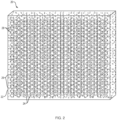
- FIG. 1 schematically depicts a vent 10 according to an embodiment of the present teachings for use in an electronic device for absorbing electromagnetic radiation.
- the vent 10 includes a body 12 that comprises at least one thermoplastic polymer and a radiation-absorbing filler 14 that is distributed within the thermoplastic polymer for absorbing electromagnetic radiation.
- the body 12 can further include one or more flame retardant additives.
- thermoplastic polymers can be employed as a constituent of the body 12.
- the thermoplastic polymer can be any of a polycarbonate, ABS (acrylonitrile butadiene styrene), polypropylene, polystyrene, polyamide, polyester, polyetherimide, liquid crystal polymer, or polyphenylene sulfide.
- the thermoplastic polymer constitutes 50 percent to 99.8 percent of the volume of the body 12.
- the concentration of the thermoplastic polymer in the body 12 can be in a range of about 50 percent to about 90 percent, or in a range of about 60 percent to about 85 percent, or in a range of about 65 percent to about 80 percent, or in a range of about 70 percent of about 95 percent by volume of the body 12.
- the radiation-absorbing filler 14 can be formed of a dielectric material that exhibits a suitable high coefficient of absorptance for at least one radiation wavelength in a range of about 1 GHz to about 110 GHz.
- the radiation-absorbing filler 14 can be a material having a bulk dielectric constant in a range of about 1 to about 150 and an absorptance coefficient in a range of about 45 m -1 to about 9000 m -1 for one or more frequencies in the range of about 1 GHz to about 110 GHz.
- the vent 10 can have a thickness (T) in a range of about 0.1 inches (2.54 mm) to about 5 inches (50.8 mm).
- the concentration of the radiation-absorbing filler and the thickness of the vent 10 can be selected such that the vent would exhibit an insertion loss in a range of -5 dB to -35 dB.
- suitable radiation-absorbing fillers include, without limitation, carbon black, carbon fiber, and graphene.
- the filler is present in the body 12 of the vent at a concentration in a range of 0.2 percent to 50 percent by volume.
- the volume concentration of the filler can be in a range of about 1 percent to about 50 percent, or about 1 percent to about 45 percent, or about 5 percent to about 35 percent, or about 10 percent to about 30 percent, or about 20 percent to about 40 percent.
- the radiation-absorbing filler is in the form of a plurality of particles having a maximum size in a range of about 1 micron to about 100 microns.
- the vent 10 can further include a plurality of openings 16 distributed throughout the body 12. While in some embodiments, the openings 16 are arranged according to a predefined geometrical array, in other embodiments the openings 16 can be randomly distributed. As discussed in more detail below, once the vent 12 is coupled to the frame of an electronic device, e.g., a computer server, the openings 16 allow for a flow of air between the interior of the electronic device and an external environment to facilitate removing heat from the interior of the device, and in some cases from the vent 10 itself. Again, as discussed in more detail below, in some cases, one or more fans are employed to facilitate such air flow between the interior of the electronic device and the external environment.
- an electronic device e.g., a computer server
- the openings 16 can have a variety of different shapes, such as, hexagonal, circular, square, rectangle, or a non-geometric shape.
- the size of the openings are chosen such that the vent 10 can provide adequate absorption of electromagnetic radiation, e.g., radiation generated from electronic components within an enclosure of the electronic device or external radiation incident on the device, while allowing a sufficient air flow therethrough for removing heat from the interior of the device.
- a maximum size of each dimension of the openings e.g., x, y, and z dimensions in a Cartesian coordinate
- a maximum size of each dimension of the openings is in a range of 0.045 inches ( 1.14 millimeters (mm)) to 5 inches ( 127 millimeters).
- the maximum size of the dimensions of the openings can be in a range of about 1.5 mm to about 120 mm, or in a range of about 2 mm to about 100 mm, or in a range of about 3 mm to about 90 mm, or in a range of about 4 mm to about 80 mm, or in a range of about 5 mm to about 70 mm.
- the openings have a hexagonal shape with a maximum dimensional size in a range of 1.14 mm to 127 mm, or any of the other ranges recited above.
- the openings can be circle-shaped with a diameter in the above ranges.
- a vent according to the present teachings can include a thermoplastic material, a radiation-absorbing filler as well as a flame retardant additive.
- FIG. 2 schematically depicts a vent 20 according to such an embodiment that includes a body 22 comprising a thermoplastic polymer, such as one or more of the thermoplastic polymers listed above, and a radiation-absorbing filler 24, such as one or more of the fillers listed above.
- a flame retardant additive 26 is distributed throughout the body 12.
- vent 20 includes a plurality of holes 28 distributed through its body 22 to allow flow of air therethrough.
- the concentration of the flame retardant additive can be, for example, in a range of 0.1 to 50 percent by volume, e.g., in a range of about 0.5 percent to about 45 percent, or in a range of about 1 percent to about 40 percent, or in a range of about 2 percent to about 35 percent, or in a range of about 2.5 percent to about 30 percent, or in a range of about 3 percent to about 25 percent, or in a range of about 4 percent to about 20 percent, or in a range of about 5 percent to about 15 percent.
- suitable flame retardant additives include, without limitation, aluminum trihydrate, aluminum hydroxide, magnesium hydroxide, antimony oxides, ammonium polyphosphate or other organo phosphorus compounds, chlorinated compounds, or brominated compounds.
- suitable chlorinated compounds include, without limitation, chlorinated paraffin oils such as Paroil and Chloroflo.
- An example of suitable brominated compounds include, without limitation, decabromodiphenyl oxide (DBDPO).
- a flame retardant additive as a constituent of the body 12 provides a number of advantages.
- the flame retardant additive can improve structural rigidity of the vent.
- the use of the flame retardant additive can allow incorporating a higher concentration of the radiation-absorbing filler in the body 12 while ensuring that the body 12 exhibits sufficient structural rigidity.
- a flame retardant additive such as those listed above, can allow incorporating the radiation-absorbing filler at a volume concentration of equal to or greater than about 15 percent in the body 12 while ensuring that the body 12 is sufficiently rigid for its intended applications (e.g., as a vent in a computer server).
- body 12 contains a concentration of the radiation-absorbing filler in a range of about 15% to about 50% by weight and a concentration of the flame retardant additive in a range of about 20% to about 50% by weight.
- the unexpected synergy between the radiation-absorbing filler and the flame retardant additive results in a vent that provides significant absorption of the electromagnetic radiation, e.g., in a frequency range of about 1 GHz to about 110 GHz (corresponding to a wavelength range of about 300 mm to 3 mm) while exhibiting a desired structural rigidity.
- FIG. 3 schematically depicts a computer server 30 having a frame 32 that provides an enclosure 33 for housing a plurality of electronic components.
- the electronic components can include a central processing unit (CPU) 34, a plurality of random access memory (RAM) modules 36, a persistent memory module 38, a communication bus 40, among other components.
- a vent 42 according to the present teachings, such as the vents 10 or 20 described above, is coupled to the frame 32 to provide electromagnetic shielding, e.g., for electromagnetic radiation in a frequency range of 1 GHz to 110 GHz.
- the vent 42 can absorb electromagnetic radiation generated by the electronic components contained in the enclosure 33 to minimize, and preferably prevent, its leakage to the external environment.
- the coupling of the vent 42 to the frame can be achieved using any known method in the art, e.g., using glue, rivets, clamps, etc.
- vent 42 allows a flow of air, via a plurality of holes 42a distributed throughout the vent 42, between the enclosure 33 and the external environment.
- a fan 44 disposed within the disclosure facilitates the air flow from inside the enclosure to the external environment via the holes provided in the vent 42. Such air flow advantageously provides cooling of the electronic components disposed within the enclosure 33.
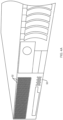
- FIGs. 4A and 4B schematically show the frame of a computer server 50 to which a vent 52 according to the present teachings, such as the above vents, is coupled.
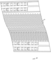
- the vent 52 includes a plurality of hexagonal openings (holes) distributed in a regular pattern to provide a honeycomb structure.
- the radiation-absorbing filler and/or the flame retardant additive can be incorporated in a thermoplastic polymer by adding the filler and/or the additive to a molten quantity of thermoplastic polymer generated by heating a plurality of polymeric pellets to an elevated temperature.
- the polymeric mixture can then be extruded using multi-lumen tooling into a continuous length and later cut to desired thickness.
- the mixture could also be injection molded into a final geometric configuration that includes the through holes or a modular section that could be additively assembled with other such pieces to form the final configuration.
- solid block of material can be fabricated either by extrusion or injection molding and through holes can be added via secondary operations such as CNC machining, waterjet or laser-cutting.
- a part was fabricated by injection molding an absorber compound containing carbon black and polypropylene into a piece 15.24 cm long x 15.24 cm wide x 0.51 cm thick (6 in. long x 6 in. wide x 0.200 in. thick). Using a waterjet cutting process, an array of hexagonal holes measuring 6mm across was drilled through the part to form a vent. The vent was tested electrically and insertion loss values for a number of frequencies were as follows: Table 1 Frequency (GHz) Insertion loss (dB) 10 -21.3 15 -21.4 20 -18.2 25 -13.0 30 -7.1 35 -5.0 40 -4.1
Landscapes
- Engineering & Computer Science (AREA)
- Microelectronics & Electronic Packaging (AREA)
- Physics & Mathematics (AREA)
- Electromagnetism (AREA)
- Computer Hardware Design (AREA)
- General Engineering & Computer Science (AREA)
- Thermal Sciences (AREA)
- Shielding Devices Or Components To Electric Or Magnetic Fields (AREA)
- Compositions Of Macromolecular Compounds (AREA)
- Fireproofing Substances (AREA)
- Cooling Or The Like Of Electrical Apparatus (AREA)
Description
- The present invention is generally directed to radiation-absorbing vents for use in an electronic device, e.g., a computer server.
- The operation of many electronic devices, such as computer servers, can result in generation of electromagnetic radiation as well as heat by their circuitry. The leakage of such electromagnetic radiation from the enclosure of such a device to the external environment can interfere with the operation of other nearby devices. Further, the heat generated by the circuitry of an electronic device needs to be removed from its enclosure to ensure proper operation.
- One conventional solution is to couple metallic vents to the frame of the electronic device. Such vents can provide openings for air flow between the enclosure and the external environment for thermal management. Moreover metallic vents may reflect interfering electromagnetic radiation back into the enclosure. Such conventional solutions, however, present a number of shortcomings. For example, electromagnetic radiation at certain frequencies may penetrate through such vents and cause interference with other electronic devices.
- Accordingly, there is a need for improved vents for use with electronic devices, and particularly computer servers.
- Examples of electromagnetic shielding or absorbing devices are described in the following.
- In
US2006086520 there is disclosed an EMI shielding enclosure having one or more EMI shielding vents as its integral part thereof. The enclosure as well as the vent is molded from a thermoplastic material filled with a conductive filler. Metal fibers, particles, flakes or metal-coated fibers are used as a filler to provide conductivity to otherwise dielectric thermoplastic matrix. Features such as bosses and grooves are provided on the vent to enable easy attachment with the shielding enclosure. - In
US5366664 a material is described for conductive electromagnetic shielding (EMS) compositions which can be formulated to provide effective shielding over a broad range of frequencies, e.g. 30 MHz. to 110 GHz. which is based on a mixture of a polymeric or liquid matrix material and a synergestic combination of conductive powders, fibers and optional flake components. The material also provides for formulations containing the above composition which are adapted for EMS applications such as pliable caulking, thermoformable shaped articles such as housings and cabinetry, flexible gasket material, shielding curtains, coatings and paints which may be applied to substrates such as glass, plastic or metal, structural composites, conformal coatings for printed circuit boards and like applications. - In
WO2014099187 there is disclosed a wireless-communications-tower component being at least partially formed from a polymer composite. The polymer composite comprises a thermoplastic polymer and a filler, where the thermoplastic polymer is non-foamed. The polymer composite has a thermal conductivity of at least 0.5 watt per meter Kelvin measured at 25 C. -
EP0982360 discloses an electromagnetic wave-shielding material which is obtained by adding conductive filler to a rubber material or a plastic material and by adding sulfur in an amount of from 4 to 16 weight parts relative to 100 weight parts of the rubber or plastic material. The electromagnetic wave-shielding material can block off the electromagnetic wave in the high frequency band. - According to a first aspect of the invention, there is provided a vent for use in an electronic device for absorbing electromagnetic radiation (EMR) as defined in claim 1. Further embodiments are defined in the dependent claims.
- Further understanding of various aspects of the present teachings can be obtained by reference to the following detailed description in conjunction with the associated drawings, which are described briefly below.
-
-
FIG. 1 schematically depicts a vent according to an embodiment of the present teachings, -
FIG. 2 schematic depicts a vent according to another embodiment of the present teachings, -
FIG. 3 schematically depict an enclosure of an electronic device, e.g., a computer server, having a frame in which a vent according to an embodiment of the present teachings is incorporated. -
FIGS. 4A and4B schematically depict another example of a vent according to an embodiment of the present teachings coupled to the frame of a computer server. - The present invention is generally directed to a vent for use with an electronic device, such as a computer server. The vent includes a porous polymeric body in which a radiation-absorbing filler is distributed. In some embodiments, the filler can absorb electromagnetic radiation at one or more frequencies in a range of 1 GHz to 110 GHz. Further, in some embodiments, a flame retardant additive is distributed within the polymeric body. The combination of the flame retardant additive and the radiation-absorbing filler can provide unexpected advantages. For example, it can help maintain the rigidity of the polymeric body for high concentrations of the radiation-absorbing filler, e.g., for concentrations of the filler greater than about 15% by weight.
- The term "thermoplastic polymer" is known in the art and is used herein consistent with its common usage. To the extent that any additional explanation may be needed, a thermoplastic polymer is a polymer (i.e., a substance having a molecular structure consisting mainly or entirely of identical units bonded together, e.g., via covalent bonds) that becomes pliable or moldable above a temperature threshold and solidifies upon cooling.
- The terms "absorptance" and "absorptance coefficient" are used herein interchangeably and consistent with common usage in the art to refer to the attenuation of the intensity of electromagnetic radiation passing through a length (z) of the medium in accordance with the following relation:

- I 0 denotes the initial intensity of the electromagnetic radiation,
- Iz denotes the intensity of the electromagnetic radiation after passage through a length (z) of the medium, and
- α denotes the absorptance coefficient.
- Further, the ratio of Iz and I 0, i.e.,

- The term "about" is used herein to indicate a variation of at most 5% about a numerical value.
-
FIG. 1 schematically depicts avent 10 according to an embodiment of the present teachings for use in an electronic device for absorbing electromagnetic radiation. Thevent 10 includes abody 12 that comprises at least one thermoplastic polymer and a radiation-absorbingfiller 14 that is distributed within the thermoplastic polymer for absorbing electromagnetic radiation. As discussed in more detail below, in some embodiments, thebody 12 can further include one or more flame retardant additives. - A variety of thermoplastic polymers can be employed as a constituent of the
body 12. By way of example and without any limitation, the thermoplastic polymer can be any of a polycarbonate, ABS (acrylonitrile butadiene styrene), polypropylene, polystyrene, polyamide, polyester, polyetherimide, liquid crystal polymer, or polyphenylene sulfide. - According to the claimed invention, the thermoplastic polymer constitutes 50 percent to 99.8 percent of the volume of the
body 12. By way of example, in some embodiments, the concentration of the thermoplastic polymer in thebody 12 can be in a range of about 50 percent to about 90 percent, or in a range of about 60 percent to about 85 percent, or in a range of about 65 percent to about 80 percent, or in a range of about 70 percent of about 95 percent by volume of thebody 12. - The radiation-absorbing
filler 14 can be formed of a dielectric material that exhibits a suitable high coefficient of absorptance for at least one radiation wavelength in a range of about 1 GHz to about 110 GHz. By way of example, the radiation-absorbingfiller 14 can be a material having a bulk dielectric constant in a range of about 1 to about 150 and an absorptance coefficient in a range of about 45 m-1 to about 9000 m-1 for one or more frequencies in the range of about 1 GHz to about 110 GHz. - In some embodiments, the
vent 10 can have a thickness (T) in a range of about 0.1 inches (2.54 mm) to about 5 inches (50.8 mm). In some such embodiments, the concentration of the radiation-absorbing filler and the thickness of thevent 10 can be selected such that the vent would exhibit an insertion loss in a range of -5 dB to -35 dB. - Some examples of suitable radiation-absorbing fillers include, without limitation, carbon black, carbon fiber, and graphene. In some embodiments, the filler is present in the
body 12 of the vent at a concentration in a range of 0.2 percent to 50 percent by volume. For example, the volume concentration of the filler can be in a range of about 1 percent to about 50 percent, or about 1 percent to about 45 percent, or about 5 percent to about 35 percent, or about 10 percent to about 30 percent, or about 20 percent to about 40 percent. - In some embodiments, the radiation-absorbing filler is in the form of a plurality of particles having a maximum size in a range of about 1 micron to about 100 microns.
- With continued reference to
FIG. 1 , thevent 10 can further include a plurality ofopenings 16 distributed throughout thebody 12. While in some embodiments, theopenings 16 are arranged according to a predefined geometrical array, in other embodiments theopenings 16 can be randomly distributed. As discussed in more detail below, once thevent 12 is coupled to the frame of an electronic device, e.g., a computer server, theopenings 16 allow for a flow of air between the interior of the electronic device and an external environment to facilitate removing heat from the interior of the device, and in some cases from thevent 10 itself. Again, as discussed in more detail below, in some cases, one or more fans are employed to facilitate such air flow between the interior of the electronic device and the external environment. - The
openings 16 can have a variety of different shapes, such as, hexagonal, circular, square, rectangle, or a non-geometric shape. In some embodiments, the size of the openings are chosen such that thevent 10 can provide adequate absorption of electromagnetic radiation, e.g., radiation generated from electronic components within an enclosure of the electronic device or external radiation incident on the device, while allowing a sufficient air flow therethrough for removing heat from the interior of the device. For example, in some embodiments, a maximum size of each dimension of the openings (e.g., x, y, and z dimensions in a Cartesian coordinate) is in a range of 0.045 inches ( 1.14 millimeters (mm)) to 5 inches ( 127 millimeters). For example, in some embodiments, the maximum size of the dimensions of the openings can be in a range of about 1.5 mm to about 120 mm, or in a range of about 2 mm to about 100 mm, or in a range of about 3 mm to about 90 mm, or in a range of about 4 mm to about 80 mm, or in a range of about 5 mm to about 70 mm. In this illustrative embodiment, the openings have a hexagonal shape with a maximum dimensional size in a range of 1.14 mm to 127 mm, or any of the other ranges recited above. In other embodiments, the openings can be circle-shaped with a diameter in the above ranges. - In some embodiments, a vent according to the present teachings can include a thermoplastic material, a radiation-absorbing filler as well as a flame retardant additive. By way of example,
FIG. 2 schematically depicts avent 20 according to such an embodiment that includes a body 22 comprising a thermoplastic polymer, such as one or more of the thermoplastic polymers listed above, and a radiation-absorbingfiller 24, such as one or more of the fillers listed above. In addition, aflame retardant additive 26 is distributed throughout thebody 12. Similar to thevent 10, vent 20 includes a plurality ofholes 28 distributed through its body 22 to allow flow of air therethrough. - The concentration of the flame retardant additive can be, for example, in a range of 0.1 to 50 percent by volume, e.g., in a range of about 0.5 percent to about 45 percent, or in a range of about 1 percent to about 40 percent, or in a range of about 2 percent to about 35 percent, or in a range of about 2.5 percent to about 30 percent, or in a range of about 3 percent to about 25 percent, or in a range of about 4 percent to about 20 percent, or in a range of about 5 percent to about 15 percent.
- Some examples of suitable flame retardant additives include, without limitation, aluminum trihydrate, aluminum hydroxide, magnesium hydroxide, antimony oxides, ammonium polyphosphate or other organo phosphorus compounds, chlorinated compounds, or brominated compounds. Some examples of suitable chlorinated compounds include, without limitation, chlorinated paraffin oils such as Paroil and Chloroflo. An example of suitable brominated compounds include, without limitation, decabromodiphenyl oxide (DBDPO).
- The incorporation of a flame retardant additive as a constituent of the
body 12 provides a number of advantages. For example, the flame retardant additive can improve structural rigidity of the vent. - In some embodiments, the use of the flame retardant additive can allow incorporating a higher concentration of the radiation-absorbing filler in the
body 12 while ensuring that thebody 12 exhibits sufficient structural rigidity. For example, the use of a flame retardant additive, such as those listed above, can allow incorporating the radiation-absorbing filler at a volume concentration of equal to or greater than about 15 percent in thebody 12 while ensuring that thebody 12 is sufficiently rigid for its intended applications (e.g., as a vent in a computer server). In some embodiments,body 12 contains a concentration of the radiation-absorbing filler in a range of about 15% to about 50% by weight and a concentration of the flame retardant additive in a range of about 20% to about 50% by weight. In such embodiments, the unexpected synergy between the radiation-absorbing filler and the flame retardant additive results in a vent that provides significant absorption of the electromagnetic radiation, e.g., in a frequency range of about 1 GHz to about 110 GHz (corresponding to a wavelength range of about 300 mm to 3 mm) while exhibiting a desired structural rigidity. -
FIG. 3 schematically depicts a computer server 30 having aframe 32 that provides anenclosure 33 for housing a plurality of electronic components. By way of example and without limitation, the electronic components can include a central processing unit (CPU) 34, a plurality of random access memory (RAM)modules 36, apersistent memory module 38, acommunication bus 40, among other components. Avent 42 according to the present teachings, such as thevents frame 32 to provide electromagnetic shielding, e.g., for electromagnetic radiation in a frequency range of 1 GHz to 110 GHz. In particular, thevent 42 can absorb electromagnetic radiation generated by the electronic components contained in theenclosure 33 to minimize, and preferably prevent, its leakage to the external environment. The coupling of thevent 42 to the frame can be achieved using any known method in the art, e.g., using glue, rivets, clamps, etc. - In addition, the
vent 42 allows a flow of air, via a plurality ofholes 42a distributed throughout thevent 42, between theenclosure 33 and the external environment. In this embodiment, afan 44 disposed within the disclosure facilitates the air flow from inside the enclosure to the external environment via the holes provided in thevent 42. Such air flow advantageously provides cooling of the electronic components disposed within theenclosure 33. - By way of further example,
FIGs. 4A and4B schematically show the frame of acomputer server 50 to which avent 52 according to the present teachings, such as the above vents, is coupled. As shown more clearly inFIG. 4B , thevent 52 includes a plurality of hexagonal openings (holes) distributed in a regular pattern to provide a honeycomb structure. - A variety of techniques can be employed to fabricate a vent according to the present teachings. For example, the radiation-absorbing filler and/or the flame retardant additive can be incorporated in a thermoplastic polymer by adding the filler and/or the additive to a molten quantity of thermoplastic polymer generated by heating a plurality of polymeric pellets to an elevated temperature. The polymeric mixture can then be extruded using multi-lumen tooling into a continuous length and later cut to desired thickness. The mixture could also be injection molded into a final geometric configuration that includes the through holes or a modular section that could be additively assembled with other such pieces to form the final configuration. Alternatively, solid block of material can be fabricated either by extrusion or injection molding and through holes can be added via secondary operations such as CNC machining, waterjet or laser-cutting.
- The following example is provided for further elucidation of various aspects of the present teachings, and is not intended to provide necessarily the optimal ways of practicing the present teachings or the optimal results that can be achieved.
- A part was fabricated by injection molding an absorber compound containing carbon black and polypropylene into a piece 15.24 cm long x 15.24 cm wide x 0.51 cm thick (6 in.
long x 6 in. wide x 0.200 in. thick). Using a waterjet cutting process, an array of hexagonal holes measuring 6mm across was drilled through the part to form a vent. The vent was tested electrically and insertion loss values for a number of frequencies were as follows:Table 1 Frequency (GHz) Insertion loss (dB) 10 -21.3 15 -21.4 20 -18.2 25 -13.0 30 -7.1 35 -5.0 40 -4.1 - Those having ordinary skill in the art will appreciate that various changes can be made to the above embodiments without departing from the scope of the invention, as defined by the appended claims.
Claims (13)
- A vent (10, 20, 42, 52) for use in an electronic device for absorbing electromagnetic radiation, comprising:a body (12) comprising at least one thermoplastic polymer and a radiation-absorbing filler (14) distributed within said thermoplastic polymer for absorbing electromagnetic radiation, wherein said filler (14) comprises any of carbon black, carbon fiber, and graphene,said body (12) further comprising a plurality of openings (16),wherein said body (12) is adapted for coupling to a frame (32) of said electronic device to absorb electromagnetic radiation and to allow heat transfer via air flow through said openings (16) between an interior of the frame (32) and an external environment, andwherein said vent (10, 20, 42, 52) exhibits an insertion loss greater than -5 dB for electromagnetic energy with a frequency in a range of 1 GHz to 110 GHz, andcharacterised in thata concentration of said thermoplastic polymer is in a range of 50 percent to 99.8 percent by volume.
- The vent of claim 1, wherein said thermoplastic polymer comprises any of a polycarbonate, ABS, polypropylene, polystyrene, polyamide, polyester, polyetherimide, liquid crystal polymer, or polyphenylene sulfide.
- The vent of claim 1, wherein a concentration of said filler (14) is in a range of 0.2 percent to 50 percent by volume.
- The vent of claim 1, wherein said body (12) further comprises a flame retardant additive (26).
- The vent of claim 4, wherein said flame retardant additive (26) comprises any of aluminum trihydrate, aluminum hydroxide, magnesium hydroxide, antimony oxides, ammonium polyphosphate or other organo phosphorus compounds, chlorinated compounds, or brominated compounds.
- The vent of claim 4 or 5, wherein a concentration of said flame retardant additive (26) is in a range of 0.01 percent to 50 percent by volume.
- The vent of claim 1, wherein said openings (16) have a largest dimension in a range of 0.114 cm (0.045 inches) to 12.7 cm (5 inches).
- The vent of claim 7, wherein said openings have a geometrical shape.
- The vent of claim 8, wherein said geometrical shape is any of circular, hexagonal, square, and rectangular shape.
- The vent of claim 1, wherein said vent (10, 20, 42, 52) exhibits an insertion loss in a range of -5 dB to -35 dB for radiation frequencies in a range of 1 GHz to 40 GHz.
- A computer enclosure (30, 50), comprising:a frame (32) for housing a plurality of electronic components,a vent (10, 20, 42, 52) adapted for coupling to the frame (32) for absorbing electromagnetic radiation, said vent defined according to any of claims 1 to 10.
- The computer enclosure of claim 11, wherein said vent (10, 20, 42, 52) exhibits an insertion loss in a range of -5 dB to -35 dB for electromagnetic energy with a frequency in a range of 1 GHz to 110 GHz.
- The computer enclosure of claim 11, wherein at least one of said enclosed electronic components comprises a central processing unit, CPU (34).
Applications Claiming Priority (3)
| Application Number | Priority Date | Filing Date | Title |
|---|---|---|---|
| US201562204814P | 2015-08-13 | 2015-08-13 | |
| US14/828,173 US9832918B2 (en) | 2015-08-13 | 2015-08-17 | EMR absorbing server vent |
| PCT/US2016/046787 WO2017027808A1 (en) | 2015-08-13 | 2016-08-12 | Emr absorbing server vent |
Publications (2)
| Publication Number | Publication Date |
|---|---|
| EP3335531A1 EP3335531A1 (en) | 2018-06-20 |
| EP3335531B1 true EP3335531B1 (en) | 2023-12-20 |
Family
ID=56799600
Family Applications (1)
| Application Number | Title | Priority Date | Filing Date |
|---|---|---|---|
| EP16756895.5A Active EP3335531B1 (en) | 2015-08-13 | 2016-08-12 | Emr absorbing server vent |
Country Status (6)
| Country | Link |
|---|---|
| US (1) | US9832918B2 (en) |
| EP (1) | EP3335531B1 (en) |
| JP (1) | JP6882259B2 (en) |
| KR (1) | KR102103656B1 (en) |
| CN (1) | CN108141988B (en) |
| WO (1) | WO2017027808A1 (en) |
Families Citing this family (7)
| Publication number | Priority date | Publication date | Assignee | Title |
|---|---|---|---|---|
| JP2019012737A (en) * | 2017-06-29 | 2019-01-24 | 北川工業株式会社 | Radio wave absorber and radio wave shielding structure |
| USD880913S1 (en) * | 2018-02-13 | 2020-04-14 | EP Family Corp. | Desk stand |
| US12004336B2 (en) * | 2019-07-19 | 2024-06-04 | Dell Products L.P. | System and method for thermal management and electromagnetic interference management |
| US11644425B2 (en) | 2019-07-19 | 2023-05-09 | Dell Products L.P. | System and method for optical state determination |
| CN114467232A (en) * | 2019-10-04 | 2022-05-10 | 莫列斯有限公司 | Method and apparatus for shielding a multi-layer multiport connector assembly from electromagnetic interference |
| USD1093379S1 (en) * | 2024-01-03 | 2025-09-16 | Dell Products L.P. | Information handling system |
| USD1107013S1 (en) * | 2024-07-05 | 2025-12-23 | X-ion GmbH | Computer case |
Citations (1)
| Publication number | Priority date | Publication date | Assignee | Title |
|---|---|---|---|---|
| EP0982360A1 (en) * | 1997-04-30 | 2000-03-01 | Tuchiyagomu Co., Ltd. | Electromagnetic wave shielding material, and electromagnetic wave shielding sheet, electric wire/cable and cable cover each made of the material |
Family Cites Families (24)
| Publication number | Priority date | Publication date | Assignee | Title |
|---|---|---|---|---|
| GB1198904A (en) | 1967-05-19 | 1970-07-15 | Hitachi Ltd | Transmission Type Interference Filter |
| JPS50155999A (en) | 1974-06-05 | 1975-12-16 | ||
| DE3784185D1 (en) | 1986-04-22 | 1993-03-25 | Yokohama Rubber Co Ltd | MULTILAYER MICROWAVE ABSORBER AND METHOD FOR THE PRODUCTION THEREOF. |
| FR2795873A1 (en) | 1989-11-17 | 2001-01-05 | Thomson Csf | Multilayer absorbing electromagnetic waves for e.g. high-intensity broadband radar stealth, exhibits conductivity gradient within each layer |
| US5366664A (en) | 1992-05-04 | 1994-11-22 | The Penn State Research Foundation | Electromagnetic shielding materials |
| US5488371A (en) | 1994-04-29 | 1996-01-30 | Litton Systems, Inc. | Radio frequency absorbing windows |
| IT1274492B (en) | 1995-05-12 | 1997-07-17 | Oto Melara Spa | STRUCTURE OF COMPOSITE MATERIAL SUITABLE TO ABSORB AND DISSIPATE THE POWER OF THE INCIDENT ELECTROMAGNETIC RADIATION, IN PARTICULAR FOR MEANS OF AIR, SHIP, AND LAND TRANSPORT AND FOR STATIONARY LAND EQUIPMENT |
| US6211458B1 (en) * | 1998-02-17 | 2001-04-03 | Parker-Hannifin Corporation | EMI shielded vent panel and method |
| EP0975207B1 (en) | 1998-07-23 | 2007-02-07 | Konica Corporation | Electromagnetic wave attenuating transparent member |
| WO2001013695A1 (en) * | 1999-08-17 | 2001-02-22 | Parker-Hannifin Corporation | Emi shielding vent panel |
| DE10033259C2 (en) | 2000-07-10 | 2003-06-26 | Univ Braunschweig Tech | Optical component |
| TWI258771B (en) * | 2001-12-04 | 2006-07-21 | Laird Technologies Inc | Methods and apparatus for EMI shielding |
| US6610922B1 (en) * | 2001-12-20 | 2003-08-26 | Cisco Technology, Inc. | Apparatus for securing an electromagnetic shield in a conductive casing |
| CA2428848A1 (en) * | 2002-05-16 | 2003-11-16 | Parker-Hannifin Corporation | Emi shielding vent panel |
| JP3772187B2 (en) * | 2002-07-18 | 2006-05-10 | 国立大学法人 北海道大学 | Electromagnetic wave absorber |
| US7038124B1 (en) * | 2002-11-19 | 2006-05-02 | Laird Technologies, Inc. | Two-piece EMI shielding vent panel |
| JP2005158960A (en) | 2003-11-25 | 2005-06-16 | Aichi Steel Works Ltd | Radio wave absorber |
| JP2006060013A (en) * | 2004-08-20 | 2006-03-02 | Denki Kagaku Kogyo Kk | Electromagnetic wave absorber |
| US20060086520A1 (en) * | 2004-10-08 | 2006-04-27 | Parker Hannifin Corp. | Electromagnetic interference shielding enclosure molded from fiber reinforced thermoplastic |
| US7280009B2 (en) | 2005-04-13 | 2007-10-09 | The Boeing Company | Radio frequency filter systems and methods |
| US7492610B2 (en) * | 2006-06-23 | 2009-02-17 | International Business Machines Corporation | Apparatus for improving server electromagnetic shielding |
| JP4518097B2 (en) * | 2007-04-13 | 2010-08-04 | ソニー株式会社 | Front structure of information processing equipment |
| KR102137296B1 (en) * | 2012-12-20 | 2020-07-23 | 다우 글로벌 테크놀로지스 엘엘씨 | Polymer composite components for wireless-communication towers |
| US20150371279A1 (en) * | 2014-06-23 | 2015-12-24 | Mastercard International Incorporated | Method and system for targeted advertising on product packaging |
-
2015
- 2015-08-17 US US14/828,173 patent/US9832918B2/en active Active
-
2016
- 2016-08-12 KR KR1020187007204A patent/KR102103656B1/en active Active
- 2016-08-12 WO PCT/US2016/046787 patent/WO2017027808A1/en not_active Ceased
- 2016-08-12 JP JP2018507610A patent/JP6882259B2/en active Active
- 2016-08-12 EP EP16756895.5A patent/EP3335531B1/en active Active
- 2016-08-12 CN CN201680047586.4A patent/CN108141988B/en active Active
Patent Citations (1)
| Publication number | Priority date | Publication date | Assignee | Title |
|---|---|---|---|---|
| EP0982360A1 (en) * | 1997-04-30 | 2000-03-01 | Tuchiyagomu Co., Ltd. | Electromagnetic wave shielding material, and electromagnetic wave shielding sheet, electric wire/cable and cable cover each made of the material |
Also Published As
| Publication number | Publication date |
|---|---|
| JP2018530147A (en) | 2018-10-11 |
| CN108141988A (en) | 2018-06-08 |
| WO2017027808A1 (en) | 2017-02-16 |
| US9832918B2 (en) | 2017-11-28 |
| EP3335531A1 (en) | 2018-06-20 |
| CN108141988B (en) | 2021-04-16 |
| KR20180066038A (en) | 2018-06-18 |
| KR102103656B1 (en) | 2020-04-22 |
| JP6882259B2 (en) | 2021-06-02 |
| US20170049011A1 (en) | 2017-02-16 |
Similar Documents
| Publication | Publication Date | Title |
|---|---|---|
| US9832918B2 (en) | EMR absorbing server vent | |
| US7488901B2 (en) | EMI absorbing shielding for a printed circuit board | |
| JP6512677B2 (en) | Resin molding | |
| US7064265B2 (en) | Reduced-gasket EMI-shielding solutions for hard disk drives and other computer components | |
| US7136008B2 (en) | Low cost electromagnetic energy absorbers manufactured from conductive loaded resin-based materials | |
| WO1993022774A1 (en) | Electromagnetic shielding materials | |
| US20090084599A1 (en) | Nano inks for imparting emi shielding to windows | |
| JP5519025B2 (en) | EMI absorber and method for producing the same | |
| US20070297160A1 (en) | Configurations for EMI Shielding Enclosures | |
| US7199310B2 (en) | Electromagnetic interference shielding structures for computer hard-drive enclosures | |
| US20080006444A1 (en) | Method for Providing Electromagnetic Interference Shielding in Electronics Enclosures by Forming Tubular Patterns in Conductive Polymer | |
| US20060086520A1 (en) | Electromagnetic interference shielding enclosure molded from fiber reinforced thermoplastic | |
| JP2005011878A (en) | Electromagnetic wave absorber | |
| JPWO2020166584A1 (en) | Heat dissipation body, heat dissipation structure and electronic equipment | |
| DE102019112411A1 (en) | Composite panel absorbing electromagnetic waves | |
| KR20140147263A (en) | Thermal electromagnetic shield composition, method for preparing carbon material reinforced complex, and plastic injection molded products | |
| KR20250115410A (en) | Polypropylene composition having improved microwave absorption and reduced microwave reflection | |
| EP2805590B1 (en) | Cooling arrangement for a heat-generating component, foam and use of a foam for a cooling arrangement | |
| JP2857960B2 (en) | Manufacturing method of radio wave absorber | |
| US20140197352A1 (en) | Methods and compositions for energy dissipation | |
| KR20220139134A (en) | Electromagnetic wave absorber | |
| CN120383806A (en) | A plastic-based electromagnetic absorption material with electromagnetic shielding function and a preparation method thereof | |
| DE102010022288A1 (en) | Variable electromagnetic vulnerability radar absorbing material system for protecting e.g. antenna, converts high frequency radiation energy by using absorbing powder on inner/outer surfaces of solid geometry, into other energy form | |
| WO2002028608A1 (en) | Method of making barium strontium titanate filled plastics | |
| DE102005003298A1 (en) | Electronic component for high-frequency applications and method for producing an electronic component for high-frequency applications |
Legal Events
| Date | Code | Title | Description |
|---|---|---|---|
| STAA | Information on the status of an ep patent application or granted ep patent |
Free format text: STATUS: THE INTERNATIONAL PUBLICATION HAS BEEN MADE |
|
| PUAI | Public reference made under article 153(3) epc to a published international application that has entered the european phase |
Free format text: ORIGINAL CODE: 0009012 |
|
| STAA | Information on the status of an ep patent application or granted ep patent |
Free format text: STATUS: REQUEST FOR EXAMINATION WAS MADE |
|
| 17P | Request for examination filed |
Effective date: 20180313 |
|
| AK | Designated contracting states |
Kind code of ref document: A1 Designated state(s): AL AT BE BG CH CY CZ DE DK EE ES FI FR GB GR HR HU IE IS IT LI LT LU LV MC MK MT NL NO PL PT RO RS SE SI SK SM TR |
|
| AX | Request for extension of the european patent |
Extension state: BA ME |
|
| DAV | Request for validation of the european patent (deleted) | ||
| DAX | Request for extension of the european patent (deleted) | ||
| RAP1 | Party data changed (applicant data changed or rights of an application transferred) |
Owner name: ARC TECHNOLOGIES LLC |
|
| STAA | Information on the status of an ep patent application or granted ep patent |
Free format text: STATUS: EXAMINATION IS IN PROGRESS |
|
| 17Q | First examination report despatched |
Effective date: 20210708 |
|
| GRAP | Despatch of communication of intention to grant a patent |
Free format text: ORIGINAL CODE: EPIDOSNIGR1 |
|
| STAA | Information on the status of an ep patent application or granted ep patent |
Free format text: STATUS: GRANT OF PATENT IS INTENDED |
|
| INTG | Intention to grant announced |
Effective date: 20230724 |
|
| GRAS | Grant fee paid |
Free format text: ORIGINAL CODE: EPIDOSNIGR3 |
|
| GRAA | (expected) grant |
Free format text: ORIGINAL CODE: 0009210 |
|
| STAA | Information on the status of an ep patent application or granted ep patent |
Free format text: STATUS: THE PATENT HAS BEEN GRANTED |
|
| AK | Designated contracting states |
Kind code of ref document: B1 Designated state(s): AL AT BE BG CH CY CZ DE DK EE ES FI FR GB GR HR HU IE IS IT LI LT LU LV MC MK MT NL NO PL PT RO RS SE SI SK SM TR |
|
| REG | Reference to a national code |
Ref country code: GB Ref legal event code: FG4D |
|
| REG | Reference to a national code |
Ref country code: CH Ref legal event code: EP |
|
| REG | Reference to a national code |
Ref country code: DE Ref legal event code: R096 Ref document number: 602016084841 Country of ref document: DE |
|
| REG | Reference to a national code |
Ref country code: IE Ref legal event code: FG4D |
|
| PG25 | Lapsed in a contracting state [announced via postgrant information from national office to epo] |
Ref country code: GR Free format text: LAPSE BECAUSE OF FAILURE TO SUBMIT A TRANSLATION OF THE DESCRIPTION OR TO PAY THE FEE WITHIN THE PRESCRIBED TIME-LIMIT Effective date: 20240321 |
|
| REG | Reference to a national code |
Ref country code: LT Ref legal event code: MG9D |
|
| PG25 | Lapsed in a contracting state [announced via postgrant information from national office to epo] |
Ref country code: LT Free format text: LAPSE BECAUSE OF FAILURE TO SUBMIT A TRANSLATION OF THE DESCRIPTION OR TO PAY THE FEE WITHIN THE PRESCRIBED TIME-LIMIT Effective date: 20231220 |
|
| REG | Reference to a national code |
Ref country code: NL Ref legal event code: MP Effective date: 20231220 |
|
| PG25 | Lapsed in a contracting state [announced via postgrant information from national office to epo] |
Ref country code: ES Free format text: LAPSE BECAUSE OF FAILURE TO SUBMIT A TRANSLATION OF THE DESCRIPTION OR TO PAY THE FEE WITHIN THE PRESCRIBED TIME-LIMIT Effective date: 20231220 |
|
| PG25 | Lapsed in a contracting state [announced via postgrant information from national office to epo] |
Ref country code: LT Free format text: LAPSE BECAUSE OF FAILURE TO SUBMIT A TRANSLATION OF THE DESCRIPTION OR TO PAY THE FEE WITHIN THE PRESCRIBED TIME-LIMIT Effective date: 20231220 Ref country code: GR Free format text: LAPSE BECAUSE OF FAILURE TO SUBMIT A TRANSLATION OF THE DESCRIPTION OR TO PAY THE FEE WITHIN THE PRESCRIBED TIME-LIMIT Effective date: 20240321 Ref country code: FI Free format text: LAPSE BECAUSE OF FAILURE TO SUBMIT A TRANSLATION OF THE DESCRIPTION OR TO PAY THE FEE WITHIN THE PRESCRIBED TIME-LIMIT Effective date: 20231220 Ref country code: ES Free format text: LAPSE BECAUSE OF FAILURE TO SUBMIT A TRANSLATION OF THE DESCRIPTION OR TO PAY THE FEE WITHIN THE PRESCRIBED TIME-LIMIT Effective date: 20231220 Ref country code: BG Free format text: LAPSE BECAUSE OF FAILURE TO SUBMIT A TRANSLATION OF THE DESCRIPTION OR TO PAY THE FEE WITHIN THE PRESCRIBED TIME-LIMIT Effective date: 20240320 |
|
| REG | Reference to a national code |
Ref country code: AT Ref legal event code: MK05 Ref document number: 1643597 Country of ref document: AT Kind code of ref document: T Effective date: 20231220 |
|
| PG25 | Lapsed in a contracting state [announced via postgrant information from national office to epo] |
Ref country code: NL Free format text: LAPSE BECAUSE OF FAILURE TO SUBMIT A TRANSLATION OF THE DESCRIPTION OR TO PAY THE FEE WITHIN THE PRESCRIBED TIME-LIMIT Effective date: 20231220 |
|
| PG25 | Lapsed in a contracting state [announced via postgrant information from national office to epo] |
Ref country code: SE Free format text: LAPSE BECAUSE OF FAILURE TO SUBMIT A TRANSLATION OF THE DESCRIPTION OR TO PAY THE FEE WITHIN THE PRESCRIBED TIME-LIMIT Effective date: 20231220 Ref country code: RS Free format text: LAPSE BECAUSE OF FAILURE TO SUBMIT A TRANSLATION OF THE DESCRIPTION OR TO PAY THE FEE WITHIN THE PRESCRIBED TIME-LIMIT Effective date: 20231220 Ref country code: NO Free format text: LAPSE BECAUSE OF FAILURE TO SUBMIT A TRANSLATION OF THE DESCRIPTION OR TO PAY THE FEE WITHIN THE PRESCRIBED TIME-LIMIT Effective date: 20240320 Ref country code: NL Free format text: LAPSE BECAUSE OF FAILURE TO SUBMIT A TRANSLATION OF THE DESCRIPTION OR TO PAY THE FEE WITHIN THE PRESCRIBED TIME-LIMIT Effective date: 20231220 Ref country code: LV Free format text: LAPSE BECAUSE OF FAILURE TO SUBMIT A TRANSLATION OF THE DESCRIPTION OR TO PAY THE FEE WITHIN THE PRESCRIBED TIME-LIMIT Effective date: 20231220 Ref country code: HR Free format text: LAPSE BECAUSE OF FAILURE TO SUBMIT A TRANSLATION OF THE DESCRIPTION OR TO PAY THE FEE WITHIN THE PRESCRIBED TIME-LIMIT Effective date: 20231220 |
|
| PG25 | Lapsed in a contracting state [announced via postgrant information from national office to epo] |
Ref country code: IS Free format text: LAPSE BECAUSE OF FAILURE TO SUBMIT A TRANSLATION OF THE DESCRIPTION OR TO PAY THE FEE WITHIN THE PRESCRIBED TIME-LIMIT Effective date: 20240420 |
|
| PG25 | Lapsed in a contracting state [announced via postgrant information from national office to epo] |
Ref country code: CZ Free format text: LAPSE BECAUSE OF FAILURE TO SUBMIT A TRANSLATION OF THE DESCRIPTION OR TO PAY THE FEE WITHIN THE PRESCRIBED TIME-LIMIT Effective date: 20231220 Ref country code: AT Free format text: LAPSE BECAUSE OF FAILURE TO SUBMIT A TRANSLATION OF THE DESCRIPTION OR TO PAY THE FEE WITHIN THE PRESCRIBED TIME-LIMIT Effective date: 20231220 |
|
| PG25 | Lapsed in a contracting state [announced via postgrant information from national office to epo] |
Ref country code: SK Free format text: LAPSE BECAUSE OF FAILURE TO SUBMIT A TRANSLATION OF THE DESCRIPTION OR TO PAY THE FEE WITHIN THE PRESCRIBED TIME-LIMIT Effective date: 20231220 |
|
| PG25 | Lapsed in a contracting state [announced via postgrant information from national office to epo] |
Ref country code: SM Free format text: LAPSE BECAUSE OF FAILURE TO SUBMIT A TRANSLATION OF THE DESCRIPTION OR TO PAY THE FEE WITHIN THE PRESCRIBED TIME-LIMIT Effective date: 20231220 Ref country code: SK Free format text: LAPSE BECAUSE OF FAILURE TO SUBMIT A TRANSLATION OF THE DESCRIPTION OR TO PAY THE FEE WITHIN THE PRESCRIBED TIME-LIMIT Effective date: 20231220 Ref country code: RO Free format text: LAPSE BECAUSE OF FAILURE TO SUBMIT A TRANSLATION OF THE DESCRIPTION OR TO PAY THE FEE WITHIN THE PRESCRIBED TIME-LIMIT Effective date: 20231220 Ref country code: IT Free format text: LAPSE BECAUSE OF FAILURE TO SUBMIT A TRANSLATION OF THE DESCRIPTION OR TO PAY THE FEE WITHIN THE PRESCRIBED TIME-LIMIT Effective date: 20231220 Ref country code: IS Free format text: LAPSE BECAUSE OF FAILURE TO SUBMIT A TRANSLATION OF THE DESCRIPTION OR TO PAY THE FEE WITHIN THE PRESCRIBED TIME-LIMIT Effective date: 20240420 Ref country code: EE Free format text: LAPSE BECAUSE OF FAILURE TO SUBMIT A TRANSLATION OF THE DESCRIPTION OR TO PAY THE FEE WITHIN THE PRESCRIBED TIME-LIMIT Effective date: 20231220 Ref country code: CZ Free format text: LAPSE BECAUSE OF FAILURE TO SUBMIT A TRANSLATION OF THE DESCRIPTION OR TO PAY THE FEE WITHIN THE PRESCRIBED TIME-LIMIT Effective date: 20231220 Ref country code: AT Free format text: LAPSE BECAUSE OF FAILURE TO SUBMIT A TRANSLATION OF THE DESCRIPTION OR TO PAY THE FEE WITHIN THE PRESCRIBED TIME-LIMIT Effective date: 20231220 |
|
| PG25 | Lapsed in a contracting state [announced via postgrant information from national office to epo] |
Ref country code: PT Free format text: LAPSE BECAUSE OF FAILURE TO SUBMIT A TRANSLATION OF THE DESCRIPTION OR TO PAY THE FEE WITHIN THE PRESCRIBED TIME-LIMIT Effective date: 20240422 Ref country code: PL Free format text: LAPSE BECAUSE OF FAILURE TO SUBMIT A TRANSLATION OF THE DESCRIPTION OR TO PAY THE FEE WITHIN THE PRESCRIBED TIME-LIMIT Effective date: 20231220 |
|
| PG25 | Lapsed in a contracting state [announced via postgrant information from national office to epo] |
Ref country code: PT Free format text: LAPSE BECAUSE OF FAILURE TO SUBMIT A TRANSLATION OF THE DESCRIPTION OR TO PAY THE FEE WITHIN THE PRESCRIBED TIME-LIMIT Effective date: 20240422 Ref country code: PL Free format text: LAPSE BECAUSE OF FAILURE TO SUBMIT A TRANSLATION OF THE DESCRIPTION OR TO PAY THE FEE WITHIN THE PRESCRIBED TIME-LIMIT Effective date: 20231220 |
|
| REG | Reference to a national code |
Ref country code: DE Ref legal event code: R097 Ref document number: 602016084841 Country of ref document: DE |
|
| PG25 | Lapsed in a contracting state [announced via postgrant information from national office to epo] |
Ref country code: DK Free format text: LAPSE BECAUSE OF FAILURE TO SUBMIT A TRANSLATION OF THE DESCRIPTION OR TO PAY THE FEE WITHIN THE PRESCRIBED TIME-LIMIT Effective date: 20231220 |
|
| PLBE | No opposition filed within time limit |
Free format text: ORIGINAL CODE: 0009261 |
|
| STAA | Information on the status of an ep patent application or granted ep patent |
Free format text: STATUS: NO OPPOSITION FILED WITHIN TIME LIMIT |
|
| PG25 | Lapsed in a contracting state [announced via postgrant information from national office to epo] |
Ref country code: SI Free format text: LAPSE BECAUSE OF FAILURE TO SUBMIT A TRANSLATION OF THE DESCRIPTION OR TO PAY THE FEE WITHIN THE PRESCRIBED TIME-LIMIT Effective date: 20231220 |
|
| PG25 | Lapsed in a contracting state [announced via postgrant information from national office to epo] |
Ref country code: SI Free format text: LAPSE BECAUSE OF FAILURE TO SUBMIT A TRANSLATION OF THE DESCRIPTION OR TO PAY THE FEE WITHIN THE PRESCRIBED TIME-LIMIT Effective date: 20231220 Ref country code: DK Free format text: LAPSE BECAUSE OF FAILURE TO SUBMIT A TRANSLATION OF THE DESCRIPTION OR TO PAY THE FEE WITHIN THE PRESCRIBED TIME-LIMIT Effective date: 20231220 |
|
| 26N | No opposition filed |
Effective date: 20240923 |
|
| REG | Reference to a national code |
Ref country code: CH Ref legal event code: PL |
|
| PG25 | Lapsed in a contracting state [announced via postgrant information from national office to epo] |
Ref country code: LU Free format text: LAPSE BECAUSE OF NON-PAYMENT OF DUE FEES Effective date: 20240812 |
|
| PG25 | Lapsed in a contracting state [announced via postgrant information from national office to epo] |
Ref country code: MC Free format text: LAPSE BECAUSE OF FAILURE TO SUBMIT A TRANSLATION OF THE DESCRIPTION OR TO PAY THE FEE WITHIN THE PRESCRIBED TIME-LIMIT Effective date: 20231220 Ref country code: CH Free format text: LAPSE BECAUSE OF NON-PAYMENT OF DUE FEES Effective date: 20240831 |
|
| REG | Reference to a national code |
Ref country code: BE Ref legal event code: MM Effective date: 20240831 |
|
| PG25 | Lapsed in a contracting state [announced via postgrant information from national office to epo] |
Ref country code: BE Free format text: LAPSE BECAUSE OF NON-PAYMENT OF DUE FEES Effective date: 20240831 |
|
| PG25 | Lapsed in a contracting state [announced via postgrant information from national office to epo] |
Ref country code: IE Free format text: LAPSE BECAUSE OF NON-PAYMENT OF DUE FEES Effective date: 20240812 |
|
| PGFP | Annual fee paid to national office [announced via postgrant information from national office to epo] |
Ref country code: DE Payment date: 20250902 Year of fee payment: 10 |
|
| PGFP | Annual fee paid to national office [announced via postgrant information from national office to epo] |
Ref country code: GB Payment date: 20250828 Year of fee payment: 10 |
|
| PGFP | Annual fee paid to national office [announced via postgrant information from national office to epo] |
Ref country code: FR Payment date: 20250828 Year of fee payment: 10 |
|
| PG25 | Lapsed in a contracting state [announced via postgrant information from national office to epo] |
Ref country code: CY Free format text: LAPSE BECAUSE OF FAILURE TO SUBMIT A TRANSLATION OF THE DESCRIPTION OR TO PAY THE FEE WITHIN THE PRESCRIBED TIME-LIMIT; INVALID AB INITIO Effective date: 20160812 |
|
| PG25 | Lapsed in a contracting state [announced via postgrant information from national office to epo] |
Ref country code: HU Free format text: LAPSE BECAUSE OF FAILURE TO SUBMIT A TRANSLATION OF THE DESCRIPTION OR TO PAY THE FEE WITHIN THE PRESCRIBED TIME-LIMIT; INVALID AB INITIO Effective date: 20160812 |