EP3335491B1 - Resource allocation signaling in a high efficiency wireless local area network preamble - Google Patents
Resource allocation signaling in a high efficiency wireless local area network preamble Download PDFInfo
- Publication number
- EP3335491B1 EP3335491B1 EP16754079.8A EP16754079A EP3335491B1 EP 3335491 B1 EP3335491 B1 EP 3335491B1 EP 16754079 A EP16754079 A EP 16754079A EP 3335491 B1 EP3335491 B1 EP 3335491B1
- Authority
- EP
- European Patent Office
- Prior art keywords
- field
- station
- resource
- communication resource
- allocation
- Prior art date
- Legal status (The legal status is an assumption and is not a legal conclusion. Google has not performed a legal analysis and makes no representation as to the accuracy of the status listed.)
- Active
Links
- 238000013468 resource allocation Methods 0.000 title claims description 179
- 230000011664 signaling Effects 0.000 title claims description 99
- 238000004891 communication Methods 0.000 claims description 134
- 230000005540 biological transmission Effects 0.000 claims description 129
- 238000000034 method Methods 0.000 claims description 53
- 238000004590 computer program Methods 0.000 claims description 3
- 238000012544 monitoring process Methods 0.000 claims description 3
- 238000009826 distribution Methods 0.000 description 12
- 230000006870 function Effects 0.000 description 7
- 238000010586 diagram Methods 0.000 description 6
- 238000005192 partition Methods 0.000 description 6
- 238000001228 spectrum Methods 0.000 description 5
- 238000005516 engineering process Methods 0.000 description 4
- 230000003287 optical effect Effects 0.000 description 3
- 230000015556 catabolic process Effects 0.000 description 2
- 230000000295 complement effect Effects 0.000 description 2
- 239000000835 fiber Substances 0.000 description 2
- 238000012986 modification Methods 0.000 description 2
- 230000004048 modification Effects 0.000 description 2
- 239000002245 particle Substances 0.000 description 2
- 238000012549 training Methods 0.000 description 2
- 108700026140 MAC combination Proteins 0.000 description 1
- 101150081243 STA1 gene Proteins 0.000 description 1
- 238000003491 array Methods 0.000 description 1
- VYLDEYYOISNGST-UHFFFAOYSA-N bissulfosuccinimidyl suberate Chemical compound O=C1C(S(=O)(=O)O)CC(=O)N1OC(=O)CCCCCCC(=O)ON1C(=O)C(S(O)(=O)=O)CC1=O VYLDEYYOISNGST-UHFFFAOYSA-N 0.000 description 1
- 230000001419 dependent effect Effects 0.000 description 1
- 238000001514 detection method Methods 0.000 description 1
- 238000012545 processing Methods 0.000 description 1
- 238000012546 transfer Methods 0.000 description 1
Images


Classifications
-
- H—ELECTRICITY
- H04—ELECTRIC COMMUNICATION TECHNIQUE
- H04L—TRANSMISSION OF DIGITAL INFORMATION, e.g. TELEGRAPHIC COMMUNICATION
- H04L5/00—Arrangements affording multiple use of the transmission path
- H04L5/003—Arrangements for allocating sub-channels of the transmission path
- H04L5/0044—Arrangements for allocating sub-channels of the transmission path allocation of payload
-
- H—ELECTRICITY
- H04—ELECTRIC COMMUNICATION TECHNIQUE
- H04B—TRANSMISSION
- H04B7/00—Radio transmission systems, i.e. using radiation field
- H04B7/02—Diversity systems; Multi-antenna system, i.e. transmission or reception using multiple antennas
- H04B7/04—Diversity systems; Multi-antenna system, i.e. transmission or reception using multiple antennas using two or more spaced independent antennas
- H04B7/0413—MIMO systems
- H04B7/0452—Multi-user MIMO systems
-
- H—ELECTRICITY
- H04—ELECTRIC COMMUNICATION TECHNIQUE
- H04L—TRANSMISSION OF DIGITAL INFORMATION, e.g. TELEGRAPHIC COMMUNICATION
- H04L27/00—Modulated-carrier systems
- H04L27/26—Systems using multi-frequency codes
- H04L27/2601—Multicarrier modulation systems
- H04L27/2602—Signal structure
-
- H—ELECTRICITY
- H04—ELECTRIC COMMUNICATION TECHNIQUE
- H04W—WIRELESS COMMUNICATION NETWORKS
- H04W72/00—Local resource management
- H04W72/04—Wireless resource allocation
-
- H—ELECTRICITY
- H04—ELECTRIC COMMUNICATION TECHNIQUE
- H04W—WIRELESS COMMUNICATION NETWORKS
- H04W72/00—Local resource management
- H04W72/20—Control channels or signalling for resource management
- H04W72/23—Control channels or signalling for resource management in the downlink direction of a wireless link, i.e. towards a terminal
-
- H—ELECTRICITY
- H04—ELECTRIC COMMUNICATION TECHNIQUE
- H04W—WIRELESS COMMUNICATION NETWORKS
- H04W84/00—Network topologies
- H04W84/02—Hierarchically pre-organised networks, e.g. paging networks, cellular networks, WLAN [Wireless Local Area Network] or WLL [Wireless Local Loop]
- H04W84/10—Small scale networks; Flat hierarchical networks
- H04W84/12—WLAN [Wireless Local Area Networks]
Definitions
- the present disclosure for example, relates to wireless communication systems, and more particularly to techniques for resource allocation signaling in a high efficiency wireless local area network (WLAN) preamble.
- WLAN wireless local area network
- Wireless communications systems are widely deployed to provide various types of communication content such as voice, video, packet data, messaging, broadcast, and so on. These systems can be multiple-access systems capable of supporting communication with multiple users by sharing the available system resources (e.g., time, frequency, and power).
- a wireless network e.g ., a WLAN, such as a Wi-Fi network conforming to one or more of the IEEE 802.11 family of standards
- a wireless network oftentimes includes an access point (AP) that communicates with one or more stations (STAs) or mobile devices.
- the AP can oftentimes be coupled to a network, such as the Internet, and may enable a station or mobile device to communicate via the network (and/or communicate with other devices coupled to the AP)
- An allocation of resources for a wireless communication can be indicated within a WLAN preamble. Different resource allocation schemes may be used to efficiently use resources and to reduce signaling complexity.
- a device may signal a resource allocation scheme in a high efficiency wireless local area network (WLAN) preamble.
- WLAN wireless local area network
- a high efficiency (HE) WLAN signaling field is used to signal a resource allocation pattern to multiple devices.
- the HE WLAN signaling field includes a common user field that is decodable by the multiple devices and includes a resource allocation field.
- the resource allocation indicates resource unit distributions to the multiple devices and indicates which resource units in a multi-user physical (PHY) layer protocol data unit (PPDU) correspond to multi-user (MU) multiple input multiple output (MIMO) (MU-MIMO) transmissions and which resource units correspond to orthogonal frequency division multiple access (OFDMA) single-user transmissions.
- the HE WLAN signaling field also includes dedicated user fields that are assigned to certain devices. The order of the dedicated user fields corresponds to the allocated resource units.
- the HE WLAN signaling field is transmitted with a WLAN preamble to the multiple devices.
- a method for wireless communication at an access point includes generating a common user field in a WLAN signaling field, the common user field decodable by a plurality of stations, the common user field comprising a resource allocation field indicating one or more communication resource units in an MU PPDU and further indicating that the one or more communication resource units in a MU-PPDU are associated with an MU-MIMO transmission or an OFDMA single-user transmission; generating, subsequent to the common user field in the WLAN signaling field, at least one station-specific field, wherein a position of the at least one station-specific field corresponds to one of the one or more communication resource units; and transmitting a WLAN preamble that includes the WLAN signaling field.
- Generating the common user field can also include generating the resource allocation field to include a first portion and a second portion, each of the first portion and the second portion including an indicator of a type of resource allocation information that is included in the respective first portion and the respective second portion.
- the indicator can include an allocation plan indicator or a resource type indicator.
- the method can also include identifying that the one or more communication resource units in an MU-PPDU are associated with an MU-MIMO transmission or an OFDMA single-user transmission based at least in part on the allocation plan indicator and the resource type indicator.
- the method can also include identifying a size of the one or more communication resource units, a number of users associated with an MU-MIMO transmission, or any combination thereof based at least in part on the allocation plan indicator and the resource type indicator.
- Generating the resource allocation field can further include including an index with the allocation plan indicator, the index associated with a resource unit allocation plan for the one or more communication resource units. Generating the resource allocation field can also include including an index with the resource type indicator, the index associated with a number of users of the one or more communication resource units. Generating the common user field can include generating the resource allocation field to include a first resource allocation plan portion and a second user number portion.
- the at least one station-specific field can be associated with an OFDMA single-user transmission in an MU-PPDU and includes a station identification field, a modulation and coding scheme field, a coding field, a number of scheduled streams field, and space time block code field, and a transmit beamforming field. Additionally or alternatively, the at least one station-specific field is associated with an MU-MIMO transmission and comprises a station identification field, a modulation and coding scheme field, a coding field, a number of scheduled streams field, and a stream index.
- the method can also include identifying that the one or more communication resource units in an MU-PPDU are for OFDMA single-user transmissions when the indicator of the first portion and the indicator of the second portion are both allocation plan indicators.
- Generating the resource allocation field can include including an index with both allocation plan indicators if a size of the one or more communication resource units is less than a predetermined threshold.
- Generating the resource allocation field can also include including an index with only one of the allocation plan indicators if a size of the one or more communication resource units is equal to or greater than a predetermined threshold.
- the method can also include identifying that the one or more communication resource units are for multi-user multi-input multi-output (MU-MIMO) when at least one of the indicator of the first portion or the indicator of the second portion is the resource type indicator.
- Generating the resource allocation field includes including the resource type indicator with both the first portion and the second portion if a size of the one or more communication resource units is less than a predetermined threshold.
- Generating the resource allocation field can also include including the allocation plan indicator with one of the first portion and the second portion, and including the resource type indicator with another of the first portion and the second portion if a size of the one or more communication resource units is less than a predetermined threshold.
- the method can also include generating a center station-specific field at a center position between a first station-specific field and a second station-specific field of the at least one station-specific field, where the center position of the center station-specific field identifies a center communication resource unit in the MU-PPDU.
- the method can also include generating a center station-specific field at a last position of the WLAN signaling field that follows the at least one station-specific field, where the last position of the center station-specific field identifies a center communication resource unit in the MU-PPDU.
- a communications device includes a processor and memory communicatively coupled to the processor, the memory comprising computer-readable code that, when executed by the processor, causes the communications device to generate a common user field in a wireless local area network (WLAN) signaling field, the common user field decodable by a plurality of stations, the common user field comprising a resource allocation field indicating one or more communication resource units in a MU-PPDU and further indicating that the one or more communication resource units are associated with an MU-MIMO transmission or an OFDMA single-user transmission; generate, subsequent to the common user field in the WLAN signaling field, at least one station-specific field, wherein a position of the at least one station-specific field corresponds to one of the one or more communication resource units; and transmit a WLAN preamble that includes the WLAN signaling field.
- WLAN wireless local area network
- a communications device includes means for generating a common user field in a wireless local area network (WLAN) signaling field, the common user field decodable by a plurality of stations, the common user field comprising a resource allocation field indicating one or more communication resource units in a MU-PPDU and further indicating that the one or more communication resource units are associated with an MU-MIMO transmission or an OFDMA single-user transmission; generating, subsequent to the common user field in the WLAN signaling field, at least one station-specific field, wherein a position of the at least one station-specific field corresponds to one of the one or more communication resource units; and transmitting a WLAN preamble that includes the WLAN signaling field.
- WLAN wireless local area network
- a non-transitory computer-readable medium storing code for wireless communication at a wireless station is disclosed.
- the code includes instructions executable to cause a communication device to generate a common user field in a wireless local area network (WLAN) signaling field, the common user field decodable by a plurality of stations, the common user field comprising a resource allocation field indicating one or more communication resource units in a MU-PPDU and further indicating that the one or more communication resource units are associated with an MU-MIMO transmission or an OFDMA single-user transmission; generate, subsequent to the common user field in the WLAN signaling field, at least one station-specific field, wherein a position of the at least one station-specific field corresponds to one of the one or more communication resource units; and transmit a WLAN preamble that includes the WLAN signaling field.
- WLAN wireless local area network
- the method includes receiving a WLAN preamble that comprises a common user field and at least one station-specific field; identifying a resource allocation field associated with the common user field indicating one or more communication resource units in a MU-PPDU and further indicating that the one or more communication resource units are associated with an MU-MIMO transmission or an OFDMA single-user transmission; and identifying a station-specific field of the at least one station-specific field associated with the station and at least one communication resource unit of the one or more communication resource units in a MU-PPDU corresponding to the station-specific field based at least in part on a position of the at least one station-specific field.
- the method can also include identifying a size of the at least one communication resource unit based at least in part on the resource allocation field.
- the method can also include identifying that the at least one communication resource unit is associated with an MU-MIMO transmission or an OFDMA single-user transmission based at least in part on the resource allocation field.
- the method can also include identifying a number of users monitoring the at least one communication resource unit associated with an MU-MIMO transmission based at least in part on the resource allocation field.
- the method can also include identifying a location for the at least one communication resource units corresponding to the station-specific field based at least in part on the resource allocation field.
- the method can also include identifying a center station-specific field at a center position between a first station-specific field and a second station specific field of the at least one station-specific field and identifying a center communication resource unit in the MU-PPDU corresponding to the center station specific field based at least in part on identifying the center station-specific field at the center position.
- the method can also include identifying a center station-specific field at a last position following the at least one station-specific field and identifying a center communication resource unit in the MU-PPDU corresponding to the center station-specific field based at least in part on identifying the center station-specific field at the last position.
- a communications device includes a processor and memory communicatively coupled to the processor, the memory comprising computer-readable code that, when executed by the processor, causes the communications device to receive a WLAN preamble that comprises a common user field and at least one station-specific field; identify a resource allocation field associated with the common user field indicating one or more communication resource units in a MU-PPDU and further indicating that the one or more communication resource units are associated with an MU-MIMO transmission or an OFDMA single-user transmission; and identify a station-specific field of the at least one station-specific field associated with the station and at least one communication resource unit of the one or more communication resource units in a MU-PPDU corresponding to the station-specific field based at least in part on a position of the at least one station-specific field.
- a communications device includes means for receiving a WLAN preamble that comprises a common user field and at least one station-specific field; identifying a resource allocation field associated with the common user field indicating one or more communication resource units in a MU-PPDU and further indicating that the one or more communication resource units are associated with an MU-MIMO transmission or an OFDMA single-user transmission; and identifying a station-specific field of the at least one station-specific field associated with the station and at least one communication resource unit of the one or more communication resource units in a MU-PPDU corresponding to the station-specific field based at least in part on a position of the at least one station-specific field.
- a non-transitory computer-readable medium storing code for wireless communication at a wireless station is disclosed.
- the code includes instructions executable to cause a communication device to receive a WLAN preamble that comprises a common user field and at least one station-specific field; identify a resource allocation field associated with the common user field indicating one or more communication resource units in a MU-PPDU and further indicating that the one or more communication resource units are associated with an MU-MIMO transmission or an OFDMA single-user transmission; and identify a station-specific field of the at least one station-specific field associated with the station and at least one communication resource unit of the one or more communication resource units in a MU-PPDU corresponding to the station-specific field based at least in part on a position of the at least one station-specific field.
- Some examples of the methods, apparatuses, or non-transitory computer-readable media described herein may further include processes, features, means, or instructions for resource allocation signaling in a high efficiency WLAN preamble.
- a device may signal a resource allocation scheme in a high efficiency wireless local area network (WLAN) preamble.
- a high efficiency (HE) WLAN signaling field is used to signal a resource allocation pattern to multiple devices.
- the HE WLAN signaling field includes a common user field that is decodable by the multiple devices and includes a resource allocation field.
- the resource allocation field indicates resource unit distributions to the multiple devices and indicates which resource units in a MU-PPDU correspond to MU-MIMO transmissions and which resource units correspond to OFDMA single-user transmissions.
- the HE WLAN signaling field also includes dedicated user fields that are assigned to certain devices. The order of the dedicated user fields corresponds to the allocated resource units.
- the HE WLAN signaling field is transmitted with a WLAN preamble to the multiple devices.
- a resource allocation field located in the common field of the HE WLAN signaling field, includes indicators that specify a transmission type (e.g., OFDMA single-user, MU-MIMO, wideband, narrowband), a resource allocation pattern, and/or the number of users assigned to a resource unit allocation.
- the resource allocation field includes indices that complement the indicators to signal different resource allocation patterns, different resource allocation sizes, and/or the number of users associated with a resource allocation pattern.
- the resource allocation field is partitioned into a first and a second portion.
- the first portion is associated with and provides resource allocation information for the first portion of a channel and the second portion is associated with and provides resource allocation information for the second portion of the channel.
- only the first portion is used (e.g., to signal OFDMA single-user wideband transmissions).
- the first portion and the second portion are complementary and indicate the number of users associated with an MU-MIMO transmission.
- the resource allocation field includes an allocation plan field and a first multi-user (MU) field and a second MU field.
- the allocation plan field is used to indicate the different resource allocation patterns that may be designated by the resource allocation field.
- the first MU field and the second MU field are used to designate the number of users associated with a resource allocation pattern for MU-MIMO transmissions.
- the first MU field corresponds to the first portion of a channel and the second MU field corresponds to the second portion of a channel ( e.g., for MU resource unit allocations that are less than 20 MHz).
- the first and second MU fields are not used ( e.g., in the case of an OFDMA single-user transmission).
- only the first MU portion is used to designate the number of users ( e.g., for a wideband MU transmission).
- the dedicated user blocks that are subsequent to the common field indicate to a device which resource allocation units are assigned to that device.
- the order by which the dedicated user blocks are generated after the common block corresponds to a resource unit.
- a device determines when a dedicated user block was received (e.g., the first user block) and identifies the corresponding allocated resource unit (e.g., the first resource unit) as being assigned to the device.
- the dedicated user block includes a station identification field to assign the dedicated user block to a device and additional control information associated with the upcoming transmission.
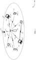
- FIG. 1 illustrates an example of a wireless communications system 100 that supports resource allocation signaling in an HE wireless local area network (WLAN) preamble in accordance with various aspects of the present disclosure.
- WLAN wireless local area network
- the WLAN 100 includes an access point (AP) 105 and stations (STAs) 110 labeled as STA_1 through STA_7.
- the STAs 110 can be mobile handsets, tablet computers, personal digital assistants (PDAs), other handheld devices, netbooks, notebook computers, tablet computers, laptops, desktop computers, display devices ( e.g., TVs, computer monitors, etc .), printers, etc. While only one AP 105 is illustrated, the WLAN 100 can have multiple APs 105.
- STAs 110 can also be referred to as a mobile stations (MS), mobile devices, access terminals (ATs), user equipment (UEs), subscriber stations (SSs), or subscriber units.
- the STAs 110 associate and communicate with the AP 105 via a communication link 115.
- Each AP 105 has a coverage area 125 such that STAs 110 within that area are within range of the AP 105.
- the STAs 110 are dispersed throughout the coverage area 125.
- Each STA 110
- a STA 110 can be covered by more than one AP 105 and can therefore associate with multiple APs 105 at different times.
- a single AP 105 and an associated set of STAs 110 is referred to as a basic service set (BSS).
- An extended service set (ESS) is a set of connected BSSs.
- a distribution system (DS) (not shown) is used to connect APs 105 in an extended service set.
- a coverage area 125 for an AP 105 can be divided into sectors making up only a portion of the coverage area (not shown).
- the WLAN 100 includes APs 105 of different types (e.g., metropolitan area, home network, etc .), with varying sizes of coverage areas and overlapping coverage areas for different technologies.
- other devices can communicate with the AP 105.
- STAs 110 While the STAs 110 are capable of communicating with each other through the AP 105 using communication links 115, STAs 110 can also communicate directly with each other via direct wireless communication links 120.
- Direct wireless communication links can occur between STAs 110 regardless of whether any of the STAs is connected to an AP 105. Examples of direct wireless communication links 120 include Wi-Fi Direct connections, connections established by using a Wi-Fi Tunneled Direct Link Setup (TDLS) link, and other peer-to-peer (P2P) group connections.
- TDLS Wi-Fi Tunneled Direct Link Setup
- P2P peer-to-peer
- the STAs 110 and APs 105 shown in FIG. 1 communicate according to the WLAN radio and baseband protocol including physical (PHY) and medium access control (MAC) layers from IEEE 802.11, and its various versions including, but not limited to, 802.11b, 802.11g, 802.11a, 802.11n, 802.11ac, 802.11ad, 802.11ah, 802.11z, etc.
- PHY physical
- MAC medium access control
- Transmissions to/from STAs 110 and APs 105 oftentimes include control information within a header that is transmitted prior to data transmissions.
- the information provided in a header is used by a device to decode the subsequent data.
- High efficiency WLAN preambles can be used to schedule multiple devices, such as STAs 110, for single-user simultaneous transmission (e.g., single-user orthogonal frequency division multiple access (SU-OFDMA)) and/or MU-MIMO transmissions (e.g., multiple input multiple output MU-MIMO).
- SU-OFDMA single-user orthogonal frequency division multiple access
- MU-MIMO e.g., multiple input multiple output MU-MIMO
- a HE WLAN signaling field is used to signal a resource allocation pattern to multiple receiving STAs 110.
- the HE WLAN signaling field includes a common user field that is decodable by multiple STAs 110, the common user field including a resource allocation field.
- the resource allocation field indicates resource unit distributions to the multiple STAs 110 and indicates which resource units in a resource unit distribution correspond to MU-MIMO transmissions and which resource units correspond to OFDMA single-user transmissions.
- the HE WLAN signaling field also includes, subsequent to the common user field, dedicated user fields that are assigned to certain STAs 110. The order in which the dedicated user fields are generated corresponds to the allocated resource units (e.g., the first dedicated user field corresponds to the first allocated resource unit).
- the HE WLAN signaling field is transmitted with a WLAN preamble to the multiple STAs 110.
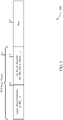
- FIG. 2 shows an example of a WLAN protocol data unit (PDU) 200 (e.g., a physical layer convergence PDU (PPDU)) resource allocation signaling in a high efficiency WLAN preamble in accordance with various aspects of the present disclosure.
- WLAN PDU 200 illustrates aspects of a transmission between a STA 110 and an AP 105, as described above with reference to FIG. 1 .
- PPDU physical layer convergence PDU
- the WLAN protocol data unit 200 includes a physical (PHY) layer header 205 and a data field 220 (e.g., a MAC protocol data unit (MPDU) or physical layer service data unit (PSDU)).
- the PHY layer header 205 includes a legacy WLAN preamble 210 and a high efficiency WLAN preamble 215.
- the preambles and data field are transmitted in the following order: legacy WLAN preamble 210, high efficiency WLAN preamble 215, data field 220.
- the WLAN protocol data unit 200 is transmitted over a radio frequency spectrum band, which in some examples may include a plurality of sub-bands.
- the radio frequency spectrum band may have a bandwidth of 80 MHz, and each of the sub-bands may have a bandwidth of 20 MHz.
- the legacy WLAN preamble 210 includes legacy short training field (STF) (L-STF) information, legacy long training field (LTF) (L-LTF) information, and legacy signaling (L-SIG) information.
- STF legacy short training field
- L-LTF legacy long training field
- L-SIG legacy signaling
- the legacy preamble is used for packet detection, automatic gain control, channel estimation, etc.
- the legacy preamble is also used to maintain compatibility with legacy devices.
- the high efficiency WLAN preamble 215 includes any of: a repeated legacy WLAN field (e.g., an RL-SIG field), a first WLAN signaling field (e.g., a first high efficiency WLAN signaling field such as HE-SIG-A), a second WLAN signaling field (e.g., a second high efficiency WLAN signaling field such as HE-SIG-B), a WLAN STF ( e.g., a high efficiency WLAN STF), and at least one WLAN LTF ( e.g., at least one high efficiency WLAN LTF).
- a repeated legacy WLAN field e.g., an RL-SIG field
- a first WLAN signaling field e.g., a first high efficiency WLAN signaling field such as HE-SIG-A
- a second WLAN signaling field e.g., a second high efficiency WLAN signaling field such as HE-SIG-B
- a WLAN STF e.g., a high efficiency WLAN STF
- the high efficiency WLAN preamble 215 enables an AP to simultaneously transmit to multiple stations (e.g., MU-MIMO) and also enables an AP to allocate resources to multiple stations for uplink/downlink transmissions (e.g., SU-OFDMA).
- the high efficiency WLAN preamble 215 uses a common signaling field and one or more dedicated ( e.g., station-specific) signaling fields to schedule resources and to indicate the scheduling to other WLAN devices.
- a device uses the scheduling to determine which resource units associated with the frequency spectrum utilized by data field 220 have been allocated to the device for forthcoming communications.
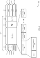
- FIG. 3 illustrates an example of aspects of a WLAN protocol data unit 300 for resource allocation signaling in a high efficiency WLAN preamble in accordance with various aspects of the present disclosure.
- WLAN protocol data unit 300 illustrates aspects of a transmission between a STA 110 and an AP 105, as described above with reference to FIGs. 1-2 .
- WLAN protocol data unit 300 includes a first WLAN signaling field 305, a second WLAN signaling field 310, a high efficiency STF 315, a high efficiency LTF 320, and a data field 325.
- the first WLAN signaling field 305 includes an HE-SIG-A 330 that is repeated across multiple sub-bands.
- the data field 325 includes data portions 335 that have been allocated to different devices. For instance, data portion 335-a is allocated to a first device, data portion 335-b to a second device, data portion 335-c to a first group of devices, and data portion 335-d to a second group of devices.
- the first WLAN signaling field 305 includes high efficiency WLAN signaling information usable by APs and stations other than a number of APs or stations identified to receive or transmit communications in the WLAN protocol data unit 300.
- the first WLAN signaling field 305 also includes information usable by the identified number of APs or stations to decode the second WLAN signaling field 310.
- the radio frequency spectrum band includes a plurality of sub-bands
- the information (e.g., HE-SIG-A 330-a) included in the first WLAN signaling field 305 is duplicated and transmitted in each sub-band of the first WLAN signaling field 305, ( e.g., HE-SIG-A 330-b to 330-d).
- the second WLAN signaling field 310 includes high efficiency WLAN signaling information usable by a number of APs or stations identified to transmit or receive communications in the WLAN protocol data unit 300. More specifically, the second WLAN signaling field 310 includes information usable by the number of APs or stations to transmit/encode or receive/decode data in the data field 220. The second WLAN signaling field 310 can be encoded separately from the first WLAN signaling field 305.
- the second WLAN signaling field 310 includes a common block field 340 that signals information to a group of devices, such as high efficiency STAs within range of an AP, and user blocks 345-a to 345-c that signal information specific to specific high efficiency STAs.
- the common block includes a resource allocation field 350 that signals to the high efficiency device how the data field 325 is partitioned amongst devices (e.g., partitions the data field into resource units), which of the resource units are associated with SU-OFDMA and which are associated with MU-MIMO. Furthermore, the order of the user blocks 345 provides a link between the device associated with the user block 345 and the resource unit that has been allocated to the device. As an example, the resource allocation field 350 partitions the data field into nine regions (e.g., 20MHz data region is partitioned into nine sub-regions that each span 26 tones). The STA addressed in the first user block corresponds to the first 26 tones, the second STA addressed in the second user block corresponds to the next 26 tones, etc.
- the common block may also include other fields, such as a LTF,
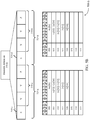
- FIG. 4 illustrates an example of aspects of a WLAN protocol data unit 400 for resource allocation signaling in a high efficiency WLAN preamble in accordance with various aspects of the present disclosure.
- WLAN protocol data unit 400 illustrates aspects of a transmission between a STA 110 and an AP 105, as described above with reference to FIGs. 1-2 .
- WLAN protocol data unit 400 includes an HE-SIG-B field 310-a, which is an example of a second WLAN signaling field 310.
- HE-SIG-B FIELD 310-a includes four sub-bands that supports four streams 405-a to 405-d of control information.
- Streams 405-c and 405-d are redundant versions of streams 405-a and 405-b, which include the resource allocation and scheduling information for a number of devices.
- a device decodes both streams to acquire all of the content signaled in the HE-SIG-B FIELD 310-a.
- a device that receives a user block within a frequency band associated with a stream 405 also receives data within the same frequency band.
- the common and dedicated content e.g. the information in common block fields 340-a and 340-b, and user blocks 345) for every other 20MHz channel are signaled together.
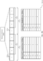
- FIGs. 5A-5F illustrate examples of resource allocation schemes 500 for resource allocation signaling in a high efficiency WLAN preamble in accordance with various aspects of the present disclosure.
- Resource allocation scheme 500 illustrates aspects of a transmission between a STA 110 and an AP 105, as described above with reference to FIGs. 1-4 .
- Resource allocation scheme 500 includes HE-SIG-B FIELD 310-b and resource allocation field 350-a.
- Resource allocation field 350-a includes a first portion 515-a and a second portion 515-b.
- the first portion 515-a includes an indicator 505-a and indices 510-a
- the second portion 515-b includes an indicator 505-b and indices 510-b.
- the resources allocated in the first portion 515-a correspond to a first portion of the bandwidth allocated to subsequent data transmissions (e.g., the first 10 MHz of a 20 MHz channel).
- the resources allocated in the second portion 515-b correspond to the second portion of the allocated bandwidth (e.g., the next 10 MHz of the 20MHz channel).
- the indicators 505, with respect to one another and based at least in part on the information provided in indices 510, indicate to a set of enhanced devices that an upcoming transmission is SU-OFDMA or MU-MIMO, the resource allocation pattern (e.g., the size of the allocated resource units), and/or the number of users participating in an MU-MIMO transmission.
- the indicators 505 are one of an allocation plan indicator or a resource type indicator.
- the first indicator 505-a is an allocation plan indicator (e.g., bit value 0) and the second indicator 505-b is an allocation plan indicator
- the indices 510-a and 510-b signal how a 20 MHz band is partitioned for an SU-OFDMA.
- the indicators are signaled with a bit and the indices are signaled using three bits to produce a resource allocation field 350-a that is constructed from eight bits. Additional examples of resource allocation schemes 500 are presented in the following discussion below.
- FIG. 5B illustrates an example of a resource allocation scheme 500-b.
- an SU-OFDMA resource allocation scheme for narrow band resource allocations e.g., less than 20 MHz
- the first indicator 505-c is signaled as an allocation plan indicator using bit value 0.
- the indices 510-a is used to signal the resource allocation pattern for a 20 MHz channel. For instance, if indices 510-a signals '000' a device that decodes the resource allocation field 350-b determines that the first 10 MHz of the 20 MHz is partitioned into four resource units that span 26 tones.
- indices 510-a signals '100' the device determines that the full first 10MHz is allocated to a single user.
- the second indicator 505-d also signals a bit value 0 and therefore signals an allocation plan indication. Similar to the above, based on indices 510-b a device that decodes resource allocation field 350-b determines how the second portion (e.g., the next 10 MHz portion of the 20 MHz channel is allocated).
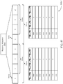
- FIG. 5C illustrates an example of a resource allocation scheme 500-c.
- an OFDMA resource allocation scheme for wide band resource allocations e.g., greater than or equal to 20 MHz
- the first indicator 505-e is signaled as an allocation plan indicator using bit value 0.
- the indices 510-a is used to signal the resource allocation pattern for a wide band channel (e.g., 20 MHz, 40 MHz, 80 MHz, etc.). For instance, if indices 510-a signals '101' a device that decodes the resource allocation field 350-c determines that the entire 20 MHz channel is allocated to a single resource unit.
- indices 510-a signals '111' the device determines that the entire 80 MHz channel is allocated to a single resource unit.
- the second indicator 505-f also signals a bit value 0, which indicates to a device that the resource allocation is not associated with MU-MIMO transmissions.
- the device identifies that the resource allocation is greater than 20 MHz and that the first and second portions of the 20 MHz are allocated. Accordingly, the device ignores signaling in indices 510-b.
- FIG. 5D illustrates an example of a resource allocation scheme 500-d.
- an MU-MIMO resource allocation scheme for narrow band resource allocations e.g., less than 20 MHz
- the first indicator 505-g is signaled as a resource type indicator using bit value 1.
- the indices 510-a is used to signal the number of users assigned to a resource unit (e.g., 2 to 8) for an MU-MIMO transmission.
- resource allocation less than 10 MHz e.g., less than 106 tones
- a device determines that since the resource assignment is less than 20 MHz (e.g., 242 tones) that the MU-MIMO assignment is 106 tones. Therefore, if indices 510-a signals '000' a device that decodes the resource allocation field 350-b determines that the first portion of the 20 MHz channel (e.g. the first 106 tones) have been assigned to two users. Alternatively, if indices 510-a signals '110' the device determines that the first portion of the channel has been assigned to eight users. In this example, the second indicator 505-h also signals a bit value 1. A device may similarly determine how many users have been scheduled for the second portion of the 20 MHz channel.
- FIG. 5E illustrates an example of a resource allocation scheme 500-e.
- an MU-MIMO resource allocation scheme for wideband band resource allocations e.g., greater than or equal to 20 MHz
- a device determines that the MU-MIMO transmission will be greater than or equal to 20 MHz.
- a device determines that a wideband MU-MIMO transmission will occur and for how many users by parsing the first and second portion of the resource allocation field 350-e.
- the first indicator 505-i is signaled as a resource allocation plan indicator using bit value 0. Accordingly, the indices 510-a is used to signal the resource allocation pattern.
- the first indices 510-a signals that the resource unit allocation is for resource units greater than or equal to 20 MHz (e.g., by signaling '101', '110', or '111').
- the device determines that the wideband resource allocation is for MU-MIMO transmission by identifying the second indicator 505-j signals a resource type indicator using bit value 1. Therefore, the device decodes indices 510-b to determine the number of users that are associated with the resource unit allocated by the first portion 515-a.
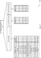
- FIG. 5F illustrates an example of a resource allocation scheme 500-f.
- a resource allocation scheme for resource allocation of a 160 MHz band is presented.
- the indices associated with '111' has been left free and therefore, for a resource type indicator, can be used to signal a 160 MHz band allocation.
- the 160 MHz can be signaled for either a SU-OFDMA transmission or an MU-MIMO transmission.
- the device signals a resource type indicator (e.g., '1') at indicator 505-1.
- a resource type indicator e.g., '1'
- Indices, 510-b is then used to specify the number of devices associated with the 160 MHz resource unit allocation.
- the first portion also signals '1111'.
- the second portion signals a resource allocation type at indicator 505-1 using a bit value 0. Accordingly, a device determines that the full 160 MHz bandwidth has been assigned to a single device.
- a device signals an 80 MHz bandwidth allocation in two 20 MHz channels in a primary 40 MHz band.
- the device determines if the 160 MHz is allocated to SU-OFDMA by identifying that a single user block is transmitted subsequent to a common block.
- the device determines the 160 MHz is associated with an MU-MIMO transmission by identifying that each common block contains an 80 MHz distribution and the same number of users and by identifying that a single set of user content is transmitted in the dedicated portion.
- a device signals a 160 MHz bandwidth allocation in two 20Mhz and also duplicating the single user block in the two 20Mhz channels.
- the device determines the 160 MHz is associated with an MU-MIMO transmission by identifying that the same number of users is duplicated on the two 20 MHz portions.
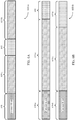
- FIGs. 6A and 6B illustrate examples of common and dedicated block signaling for an HE-SIG-B field 600 that supports resource allocation signaling in a high efficiency WLAN preamble in accordance with aspects of the present invention.
- HE-SIG-B field 600 includes a common block 605, first dedicated content blocks 610-a associated with the first portion of a channel bandwidth, second dedicated content block 610-b associated with the second portion of the channel bandwidth, and a center dedicated content block 615 associated with a center tone resource unit.
- FIG. 6A illustrates an example of the signaling in an HE-SIG-B field 600-a to indicate how the center 26 tones of a resource allocation are allocated to a certain user.
- a resource distribution such as provided in FIG. 5B allocates four 26 tone resource units to a first portion of a channel and four 26 tone resource unit to a second portion of a channel. This leaves 13 tones at the end of the first portion and the beginning of the second portion for a total of 26 central tones.
- This center 26 tone resource unit is implicitly signaled to a specific user via dedicated content block 615.
- the devices that receive HE-SIG-B field 600-a identify that the resource unit allocation in the first dedicated content blocks 610-a and the second dedicated content blocks 610-b are for resource unit sizes that are less than 20 MHz. Furthermore, the device identifies a central user block, such as a user block 345 described in FIGs. 3 and/or 4, in the center of the user block distribution scheme. The device associated with the central user block corresponding to the center dedicated content block 615 identifies that the center 26 tones are allocated to the associated device.
- FIG. 6B illustrates an example of the signaling in an HE-SIG-B field 600-b to indicate how the center 26 tones of a resource allocation are allocated to a certain user for a wideband allocation. For instance when the resource unit allocation is 80 MHz an extra 26 tone RU is available between two 40 MHz resource units.
- the first common block 605-a is associated with the second and fourth 20 MHz resource units, while common block 605-b is associated with the first and third 20 MHz resource units.
- the dedicated content for the 26 center tones is provided at the end of the primary 20 MHz channel in center dedicated content block 615-a.
- the secondary 20 MHz channel includes a padding field 620 to compensate for the disparity in signaling between the secondary and primary 20 MHz channels.
- FIG. 7 illustrates an example of a resource allocation scheme 700 that supports resource allocation signaling in a high efficiency WLAN preamble in accordance with aspects of the present invention.
- Resource allocation field 350-g includes an allocation plan field 705, a first MU-MIMO field 710 for the first portion of a channel, and a second MU-MIMO field 715 for the second portion of the channel.
- the allocation plan field 705 corresponds to each of the different allocations associated with an allocation plan. For instance, if nine 26 tone resource units are allocated then there is one allocation pattern to consider. For the allocation plan provided in this example, the different number of allocations total 29 and can be represented using 5 bits.
- the first MU-MIMO field 710 is used to indicate the number of MU-MIMO users associated with resource units in a first channel portion
- the second MU-MIMO field 715 is used to indicate the number of MU-MIMO users associated with a second channel portion. For instance, for a resource allocation that includes two 106 tone resource units, the number of users indicated in the first MU-MIMO field 710 corresponds to the first 106 tones, while the number of users in the second MU-MIMO field 715 corresponds to the second 106 tones.
- the first MU-MIMO field 710 indicates the number of users associated with the wideband allocation and the second MU-MIMO field 715 is unused.
- the first MU-MIMO field 710 and the second MU-MIMO field 715 are unused.
- the first MU-MIMO field 710 and the second MU-MIMO field 715 may also be used to indicate that the first and second portions are associated with a SU-OFDMA transmissions, the first portion is SU-OFDMA and the second portion is MU-MIMO, and the like.
- FIGs. 8A and 8B illustrate examples of HE-SIG-B field 800 that supports resource allocation signaling in a high efficiency WLAN preamble in accordance with aspects of the present invention.
- HE-SIG-B field 800 includes dedicated user block 805, which includes additional fields, such as a station identification (ID) field 810, a spatial stream indicator 815, a transmit beamforming field 820, a space time block coding (STBC) field, a modulation coding scheme (MCS) field, a coding field 835, and a stream index 840.
- ID station identification
- STBC space time block coding
- MCS modulation coding scheme
- FIG. 8A illustrates a dedicated user block 805-a that is associated with SU-OFDMA transmissions.
- the station ID field 810 is used to identify an intended recipient for the user block
- the spatial stream indicator 815 indicates the number of scheduled streams scheduled for a device
- transmit beamforming field 820 which indicates whether transmit beamforming is utilized for transmission to the device
- STBC field 825 which indicates the space time block code used for a transmission to the device
- the MCS field 830 which indicates the modulation and coding scheme used for the corresponding data transmission
- the coding field 835 As explained above, the order that the dedicated user blocks 805 are transmitted corresponds to the resource unit allocation. That is, each resource unit is associated with a position of each user block.
- FIG. 8B illustrates a dedicated user block 805-b that is associated with MU-MIMO transmissions.
- the dedicated user block 805-b includes a station ID field 810-a, spatial stream indicator 815, stream index 840, which indicates the index of the first stream and additional streams assigned to the device designated in the station ID field 810-a, MCS field 830-a, and coding field 835-a.
- Group IDs can be indicated in the common block for MU-MIMO allocations.
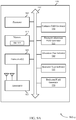
- FIG. 9A shows a block diagram 900-a of an example wireless device 990 that supports resource allocation signaling in a HE WLAN preamble in accordance with various aspects of the present disclosure, and with respect to FIGs. 1-8B .
- the wireless device 990 which may be an example of a STA 110 or an AP 105, includes a common field generator 930, a resource allocation field generator 935, an allocation plan indicator 940, a resource type indicator 945, and a dedicated field generator 950.
- the processor 905, memory 910, transceiver(s) 920, the common field generator 930, resource allocation field generator 935, allocation plan indicator 940, resource type indicator 945, and dedicated field generator 950 are communicatively coupled with a bus 955, which enables communication between these components.
- the antenna(s) 925 are communicatively coupled with the transceiver(s) 920.
- the processor 905 is an intelligent hardware device, such as a central processing unit (CPU), a microcontroller, an application-specific integrated circuit (ASIC), etc.
- the processor 905 processes information received through the transceiver(s) 920 and information to be sent to the transceiver(s) 920 for transmission through the antenna(s) 925.
- the memory 910 stores computer-readable, computer-executable software (SW) code 915 containing instructions that, when executed, cause the processor 905 or another one of the components of the wireless device 990 to perform various functions described herein, for example, triggering a roaming scan and determining whether to roam to a different channel.
- SW software
- the transceiver(s) 920 communicate bi-directionally with other wireless devices, such as APs 105, base station 150, STAs 110, or other devices.
- the transceiver(s) 920 include a modem to modulate packets and frames and provide the modulated packets to the antenna(s) 925 for transmission.
- the modem is additionally used to demodulate packets received from the antenna(s) 925.
- the common field generator 930, resource allocation field generator 935, allocation plan indicator 940, resource type indicator 945, and dedicated field generator 950 implement the features described with reference to FIGs. 1-8B , as further explained below.
- FIG. 9A shows only one possible implementation of a device executing the features of FIGS. 1-8B . While the components of FIG. 9A are shown as discrete hardware blocks (e.g., ASICs, field programmable gate arrays (FPGAs), semi-custom integrated circuits, etc .) for purposes of clarity, it will be understood that each of the components may also be implemented by multiple hardware blocks adapted to execute some or all of the applicable features in hardware. Alternatively, features of two or more of the components of FIG. 9A may be implemented by a single, consolidated hardware block. For example, a single transceiver 920 chip may implement the processor 905, memory 910, common field generator 930, resource allocation field generator 935, allocation plan indicator 940, resource type indicator 945, and dedicated field generator 950.
- FIG. 9B shows a block diagram 900-b of another example of a wireless device 990-a in which the features of the common field generator 930-a, resource allocation field generator 935-a, allocation plan indicator 940-a, resource type indicator 945-a, and dedicated field generator 950-a are implemented as computer-readable code stored on memory 910-a and executed by one or more processors 905-a.
- Other combinations of hardware/software may be used to perform the features of one or more of the components of FIGS. 9A-9B .
- FIG. 10 shows a flow chart that illustrates one example of a method 1000 for wireless communication, in accordance with various aspects of the present disclosure.
- the method 1000 can be performed by any of the wireless devices 990, APs 105, or STAs 110 discussed in the present disclosure, but for clarity the method 1000 will be described from the perspective of wireless device 990 and wireless device 990-a, of FIGs. 9A and 9B .
- the method 1000 illustrates a procedure by which a device, such as a STA 110 or an AP 105, generates a WLAN signaling field that includes a common user field that is decodable by multiple stations and that comprises a resource allocation field that indicates one or more communication resource units in a MU-PPDU and further indicates that a communication resource unit is associated with a MU-MIMO or an OFDMA single-user transmissions.
- the device also generates in the WLAN signaling field, subsequent to the common field, station specific fields, where the position of the station specific fields corresponds to the resource units allocated by the resource allocation field and transmits a WLAN preamble including the WLAN signaling field.
- the common field generator 930 is used to generate a common user field in a WLAN signaling field.
- the common user field is decodable by multiple stations and includes a resource allocation field that partitions a set of frequency resources between multiple devices.
- the resource allocation field generator 935 generates the resource allocation field.
- the resource allocation field indicates a resource unit allocation pattern (e.g., a breakdown of the set of frequency resources into one or more resource units) and also indicates that a resource unit in an MU-PPDU is associated with an MU-MIMO transmission or an OFDMA single-user transmission.
- the resource allocation field generator 935 determines if a resource unit allocation for a MU-PPDU is associated with an OFDMA single-user transmission (e.g., if the resource unit allocation pattern is intended for single device communication).
- the resource allocation field generator 935 determines if the resource unit allocation allocates resource units that are less than 20 MHz in frequency.
- the allocation plan indicator 940 is used to indicate to a device that a following indices are associated with a resource distribution. And the following indices is used to designate a resource pattern and the size of the resource units.
- the resource allocation field generator 935 determines an allocation plan for the first and second portion of a 20MHz band.
- the allocation plan indicator 940 is used to indicate to a device that a following index is associated with a resource distribution.
- the following index designates resource unit patterns that include resource units that span up to 52 tones.
- the resource allocation field generator 935 further partitions a 20 MHz bandwidth into first and second 10 MHz portions.
- a first and second allocation plan indicator 940 and corresponding resource allocation indices are provided for both the first and second portion.
- the resource allocation field generator 935 determines an allocation plan for the full resource unit.
- the allocation plan indicator 940 is used to indicate to a device that a following index is associated with a resource distribution.
- the following index designates single resource units that include 242 to 996 tones in frequency (e.g., 20 MHz to 80 MHz).
- the resource allocation field generator 935 determines if the resource allocation is less than 20 MHz.
- the resource type indicator 945 is used to indicate to a device that the following indices are associated with the number of users assigned to receive information over a resource unit.
- the resource allocation field generator 935 indicates that the transmission is an MU-MIMO transmission by including the resource type indicator 945 in the resource allocation field.
- the resource unit associated with the resource type indicator 945 may implicitly be determined to be 106 tones based on identifying that the resource units are less than 20 MHz and by determining that MU-MIMO allocations less than 106 tones are not supported.
- the resource allocation field generator 935 partitions the 20 MHz bandwidth into first and second 10 MHz portions.
- a first and second resource type indicator 945 is associated with both the first and second portions along with the following indices to designate the number of users for a first MU transmission over the first portion and the number of users for a second MU transmission over the second portion.
- the resource type indicator 945 can also be combined with the allocation plan indicator to indicate that a first portion is associated with an OFDMA single-user transmission and a second portion is associated with an MU-MIMO transmission and vice versa.
- the indices included in the resource allocation field and following the resource type indicator are used to indicate the number of users that are associated with the allocated resource units in both the first and second portions.
- the resource allocation field generator 935 indicates that the transmission is a wideband MU-MIMO transmission by including the allocation plan indicator 940 in the resource allocation field and by indicating with the following indices that the resource unit distribution is greater than 20 MHz. Furthermore, to distinguish the wideband MU-MIMO transmission form the wideband OFDMA single-user transmission, a resource type indicator 945 is included in the second portion of the resource allocation field.
- the indices following the resource type indicator 945 is used to indicate the number of users participating in the wideband MU-MIMO transmission.
- dedicated field generator 950 generates the dedicated user fields subsequent to the common field.
- the dedicated field generator 950 generates the dedicated user fields in an order that corresponds to the resource unit allocation pattern.
- the first portion of a 20 MHz band may be allocated to four 26 tone resource units and the second portion of the 20 MHz band may also be allocated to four 26 tone resource units.
- the first dedicated user block may correspond to the first 26 tone resource unit and by extension the device assigned to the first dedicated user block is allocated the first 26 tone resource unit.
- there are 26 tones in the center of the 20 MHz bandwidth that are not assigned by the resource allocation pattern e.g., 13 unassigned tones in the first portion and 13 unassigned tones in the second portion).
- the dedicated field generator 950 inserts between the dedicated user blocks corresponding to the first portion and the dedicated user block corresponding to the second portion a dedicated user block corresponding to the center tones. Similarly, for resource unit allocations of 80 MHz or 160 MHz, the center 26 tones are unassigned. In this example, the dedicated field generator 950 generates a dedicated user block corresponding to the center tones at the end of the primary 20 MHz channel including the common and dedicated portions.
- the WLAN signaling field is included in the high efficiency WLAN preamble and a WLAN preamble, which includes the high efficiency WLAN preamble, is transmitted over the WLAN channel.
- FIG. 11 shows a flow chart that illustrates one example of a method 1100 for wireless communication, in accordance with various aspects of the present disclosure.
- the method 1000 can be performed by one of the wireless devices 990, APs 105, or STAs 110 discussed in the present disclosure, but for clarity the method 1000 will be described from the perspective of wireless device 990 and wireless device 990-a, of FIGs. 9A and 9B .
- the method 1100 illustrates another procedure by which a device, such as a STA 110 or an AP 105, generates a WLAN signaling field that includes a common user field that is decodable by multiple stations and that comprises a resource allocation field that indicates one or more communication resource units in a MU-PPDU and further indicates that a communication resource unit is associated with a multi-user or an OFDMA single-user transmissions.
- the device also generates in the WLAN signaling field, subsequent to the common field, station specific fields, where the position of the station specific fields corresponds to the resource units allocated by the resource allocation field and transmits a WLAN preamble including the WLAN signaling field.
- the common field generator 930 is used to generate a common user field in a WLAN signaling field.
- the common user field is decodable by multiple stations and includes a resource allocation field that partitions a set of frequency resources between multiple devices.
- the resource allocation field generator 935 generates the resource allocation field.
- the resource allocation field indicates a resource unit allocation pattern (e.g., a breakdown of the set of frequency resources into one or more resource units) and also indicates that a resource unit in an MU-PPDU is associated with an MU-MIMO transmission or an OFDMA single-user transmission.
- the resource allocation field includes an allocation plan field, and multi-user fields that correspond to a first and second portion of a channel, as generally described in FIG. 7 .
- the resource allocation field generator 935 determines if a resource unit allocation in a MU-PPDU is associated with an OFDMA single-user transmission (e.g., if the resource unit allocation pattern is intended for single device communication).
- the resource allocation field generator 935 generates the allocation plan field.
- the allocation plan field indicates the resource allocation pattern from a number of available resource allocation patterns (e.g., using a 5 bit look up table) via an allocation plan indicator 940. For OFDMA single-user transmission only the allocation plan field is utilized.
- the allocation plan field can indicate both narrow band (e.g., less than 20 MHz) and wide band (e.g., greater than or equal to 20 MHz) transmissions to a device.
- the resource allocation field generator 935 determines whether the resource unit allocation includes resource units less than 20 MHz.
- the resource type indicator 945 identifies that a resource unit is associated with an MU-MIMO transmission.
- the resource type indicator 945 indicates the number of users assigned to the resource unit associated with the first portion of the 20 MHz in a first MU field and the number of users assigned to the second portion of the 20 MHz in a second MU field.
- the resource allocation field generator will not support MU-MIMO transmissions. Accordingly, MU fields included in the resource type indicator are unused for MU-MIMO transmissions less than 106 tones in frequency.
- the resource type indicator 945 uses the first MU field to indicate the number of users associated with the wideband MU-MIMO transmission.
- dedicated field generator 950 generates the dedicated user fields subsequent to the common field.
- the dedicated field generator 950 generates the dedicated user fields in an order that corresponds to the resource unit allocation pattern.
- the allocation plan indicator 940 indicates the resource allocation pattern (e.g., nine 26 tone resource units) that includes the center resource unit implicitly signaled in method 1000.
- Each dedicated user field then corresponds to the nine resource units (e.g., the first user field corresponds to the first allocated resource unit, the second user field to the second allocated resource unit, and so on.)
- the WLAN signaling field is included in the high efficiency WLAN preamble and a WLAN preamble, which includes the high efficiency WLAN preamble, is transmitted over the WLAN channel.
- a WLAN preamble which includes the high efficiency WLAN preamble
- Information and signals may be represented using any of a variety of different technologies and techniques.
- data, instructions, commands, information, signals, bits, symbols, and chips that may be referenced throughout the above description may be represented by voltages, currents, electromagnetic waves, magnetic fields or particles, optical fields or particles, or any combination thereof.
- a general-purpose processor may be a microprocessor, but in the alternative, the processor may be any conventional processor, controller, microcontroller, or state machine.
- a processor may also be implemented as a combination of computing devices, e.g., a combination of a DSP and a microprocessor, multiple microprocessors, one or more microprocessors in conjunction with a DSP core, or any other such configuration.
- the functions described herein may be implemented in hardware, software executed by a processor, firmware, or any combination thereof. If implemented in software executed by a processor, the functions may be stored on or transmitted over as one or more instructions or code on a computer-readable medium. For example, due to the nature of software, functions described above can be implemented using software executed by a processor, hardware, firmware, hardwiring, or combinations of any of these. Features implementing functions may also be physically located at various positions, including being distributed such that portions of functions are implemented at different physical locations. As used herein, including in the claims, the term "and/or," when used in a list of two or more items, means that any one of the listed items can be employed by itself, or any combination of two or more of the listed items can be employed.
- compositions can contain A alone; B alone; C alone; A and B in combination; A and C in combination; B and C in combination; or A, B, and C in combination.
- “or” as used in a list of items indicates a disjunctive list such that, for example, a list of "at least one of A, B, or C” means A or B or C or AB or AC or BC or ABC ( i.e., A and B and C).
- Computer-readable media includes both computer storage media and communication media including any medium that facilitates transfer of a computer program from one place to another.
- a storage medium may be any available medium that can be accessed by a general purpose or special purpose computer.
- computer-readable media can comprise RAM, ROM, EEPROM, flash memory, CD-ROM or other optical disk storage, magnetic disk storage or other magnetic storage devices, or any other medium that can be used to carry or store desired program code means in the form of instructions or data structures and that can be accessed by a general-purpose or special-purpose computer, or a general-purpose or special-purpose processor.
- any connection is properly termed a computer-readable medium.
- Disk and disc include compact disc (CD), laser disc, optical disc, digital versatile disc (DVD), floppy disk and Blu-ray disc where disks usually reproduce data magnetically, while discs reproduce data optically with lasers. Combinations of the above are also included within the scope of computer-readable media.
Description
- The present disclosure, for example, relates to wireless communication systems, and more particularly to techniques for resource allocation signaling in a high efficiency wireless local area network (WLAN) preamble.
- Wireless communications systems are widely deployed to provide various types of communication content such as voice, video, packet data, messaging, broadcast, and so on. These systems can be multiple-access systems capable of supporting communication with multiple users by sharing the available system resources (e.g., time, frequency, and power). A wireless network (e.g., a WLAN, such as a Wi-Fi network conforming to one or more of the IEEE 802.11 family of standards) oftentimes includes an access point (AP) that communicates with one or more stations (STAs) or mobile devices. The AP can oftentimes be coupled to a network, such as the Internet, and may enable a station or mobile device to communicate via the network (and/or communicate with other devices coupled to the AP)
- Documents
US 2014/369276 ,US 2015/163028 andUS 2014/328249 describe systems and methods for generating packets comprising signalling fields for assignment of resources. - An allocation of resources for a wireless communication can be indicated within a WLAN preamble. Different resource allocation schemes may be used to efficiently use resources and to reduce signaling complexity.
- The invention consists of methods as defined in
independent claims - A method for wireless communication at an access point is described. The method includes generating a common user field in a WLAN signaling field, the common user field decodable by a plurality of stations, the common user field comprising a resource allocation field indicating one or more communication resource units in an MU PPDU and further indicating that the one or more communication resource units in a MU-PPDU are associated with an MU-MIMO transmission or an OFDMA single-user transmission; generating, subsequent to the common user field in the WLAN signaling field, at least one station-specific field, wherein a position of the at least one station-specific field corresponds to one of the one or more communication resource units; and transmitting a WLAN preamble that includes the WLAN signaling field.
- Generating the common user field can also include generating the resource allocation field to include a first portion and a second portion, each of the first portion and the second portion including an indicator of a type of resource allocation information that is included in the respective first portion and the respective second portion. The indicator can include an allocation plan indicator or a resource type indicator.
- The method can also include identifying that the one or more communication resource units in an MU-PPDU are associated with an MU-MIMO transmission or an OFDMA single-user transmission based at least in part on the allocation plan indicator and the resource type indicator. The method can also include identifying a size of the one or more communication resource units, a number of users associated with an MU-MIMO transmission, or any combination thereof based at least in part on the allocation plan indicator and the resource type indicator.
- Generating the resource allocation field can further include including an index with the allocation plan indicator, the index associated with a resource unit allocation plan for the one or more communication resource units. Generating the resource allocation field can also include including an index with the resource type indicator, the index associated with a number of users of the one or more communication resource units. Generating the common user field can include generating the resource allocation field to include a first resource allocation plan portion and a second user number portion. The at least one station-specific field can be associated with an OFDMA single-user transmission in an MU-PPDU and includes a station identification field, a modulation and coding scheme field, a coding field, a number of scheduled streams field, and space time block code field, and a transmit beamforming field. Additionally or alternatively, the at least one station-specific field is associated with an MU-MIMO transmission and comprises a station identification field, a modulation and coding scheme field, a coding field, a number of scheduled streams field, and a stream index.
- The method can also include identifying that the one or more communication resource units in an MU-PPDU are for OFDMA single-user transmissions when the indicator of the first portion and the indicator of the second portion are both allocation plan indicators. Generating the resource allocation field can include including an index with both allocation plan indicators if a size of the one or more communication resource units is less than a predetermined threshold. Generating the resource allocation field can also include including an index with only one of the allocation plan indicators if a size of the one or more communication resource units is equal to or greater than a predetermined threshold.
- The method can also include identifying that the one or more communication resource units are for multi-user multi-input multi-output (MU-MIMO) when at least one of the indicator of the first portion or the indicator of the second portion is the resource type indicator. Generating the resource allocation field includes including the resource type indicator with both the first portion and the second portion if a size of the one or more communication resource units is less than a predetermined threshold. Generating the resource allocation field can also include including the allocation plan indicator with one of the first portion and the second portion, and including the resource type indicator with another of the first portion and the second portion if a size of the one or more communication resource units is less than a predetermined threshold.
- The method can also include generating a center station-specific field at a center position between a first station-specific field and a second station-specific field of the at least one station-specific field, where the center position of the center station-specific field identifies a center communication resource unit in the MU-PPDU. The method can also include generating a center station-specific field at a last position of the WLAN signaling field that follows the at least one station-specific field, where the last position of the center station-specific field identifies a center communication resource unit in the MU-PPDU.
- A communications device includes a processor and memory communicatively coupled to the processor, the memory comprising computer-readable code that, when executed by the processor, causes the communications device to generate a common user field in a wireless local area network (WLAN) signaling field, the common user field decodable by a plurality of stations, the common user field comprising a resource allocation field indicating one or more communication resource units in a MU-PPDU and further indicating that the one or more communication resource units are associated with an MU-MIMO transmission or an OFDMA single-user transmission; generate, subsequent to the common user field in the WLAN signaling field, at least one station-specific field, wherein a position of the at least one station-specific field corresponds to one of the one or more communication resource units; and transmit a WLAN preamble that includes the WLAN signaling field.
- A communications device includes means for generating a common user field in a wireless local area network (WLAN) signaling field, the common user field decodable by a plurality of stations, the common user field comprising a resource allocation field indicating one or more communication resource units in a MU-PPDU and further indicating that the one or more communication resource units are associated with an MU-MIMO transmission or an OFDMA single-user transmission; generating, subsequent to the common user field in the WLAN signaling field, at least one station-specific field, wherein a position of the at least one station-specific field corresponds to one of the one or more communication resource units; and transmitting a WLAN preamble that includes the WLAN signaling field.
- A non-transitory computer-readable medium storing code for wireless communication at a wireless station is disclosed. The code includes instructions executable to cause a communication device to generate a common user field in a wireless local area network (WLAN) signaling field, the common user field decodable by a plurality of stations, the common user field comprising a resource allocation field indicating one or more communication resource units in a MU-PPDU and further indicating that the one or more communication resource units are associated with an MU-MIMO transmission or an OFDMA single-user transmission; generate, subsequent to the common user field in the WLAN signaling field, at least one station-specific field, wherein a position of the at least one station-specific field corresponds to one of the one or more communication resource units; and transmit a WLAN preamble that includes the WLAN signaling field.
- Another method for wireless communication is described. The method includes receiving a WLAN preamble that comprises a common user field and at least one station-specific field; identifying a resource allocation field associated with the common user field indicating one or more communication resource units in a MU-PPDU and further indicating that the one or more communication resource units are associated with an MU-MIMO transmission or an OFDMA single-user transmission; and identifying a station-specific field of the at least one station-specific field associated with the station and at least one communication resource unit of the one or more communication resource units in a MU-PPDU corresponding to the station-specific field based at least in part on a position of the at least one station-specific field.
- The method can also include identifying a size of the at least one communication resource unit based at least in part on the resource allocation field. The method can also include identifying that the at least one communication resource unit is associated with an MU-MIMO transmission or an OFDMA single-user transmission based at least in part on the resource allocation field. The method can also include identifying a number of users monitoring the at least one communication resource unit associated with an MU-MIMO transmission based at least in part on the resource allocation field. The method can also include identifying a location for the at least one communication resource units corresponding to the station-specific field based at least in part on the resource allocation field.
- The method can also include identifying a center station-specific field at a center position between a first station-specific field and a second station specific field of the at least one station-specific field and identifying a center communication resource unit in the MU-PPDU corresponding to the center station specific field based at least in part on identifying the center station-specific field at the center position. The method can also include identifying a center station-specific field at a last position following the at least one station-specific field and identifying a center communication resource unit in the MU-PPDU corresponding to the center station-specific field based at least in part on identifying the center station-specific field at the last position.
- A communications device includes a processor and memory communicatively coupled to the processor, the memory comprising computer-readable code that, when executed by the processor, causes the communications device to receive a WLAN preamble that comprises a common user field and at least one station-specific field; identify a resource allocation field associated with the common user field indicating one or more communication resource units in a MU-PPDU and further indicating that the one or more communication resource units are associated with an MU-MIMO transmission or an OFDMA single-user transmission; and identify a station-specific field of the at least one station-specific field associated with the station and at least one communication resource unit of the one or more communication resource units in a MU-PPDU corresponding to the station-specific field based at least in part on a position of the at least one station-specific field.
- A communications device includes means for receiving a WLAN preamble that comprises a common user field and at least one station-specific field; identifying a resource allocation field associated with the common user field indicating one or more communication resource units in a MU-PPDU and further indicating that the one or more communication resource units are associated with an MU-MIMO transmission or an OFDMA single-user transmission; and identifying a station-specific field of the at least one station-specific field associated with the station and at least one communication resource unit of the one or more communication resource units in a MU-PPDU corresponding to the station-specific field based at least in part on a position of the at least one station-specific field.
- A non-transitory computer-readable medium storing code for wireless communication at a wireless station is disclosed. The code includes instructions executable to cause a communication device to receive a WLAN preamble that comprises a common user field and at least one station-specific field; identify a resource allocation field associated with the common user field indicating one or more communication resource units in a MU-PPDU and further indicating that the one or more communication resource units are associated with an MU-MIMO transmission or an OFDMA single-user transmission; and identify a station-specific field of the at least one station-specific field associated with the station and at least one communication resource unit of the one or more communication resource units in a MU-PPDU corresponding to the station-specific field based at least in part on a position of the at least one station-specific field.
- Some examples of the methods, apparatuses, or non-transitory computer-readable media described herein may further include processes, features, means, or instructions for resource allocation signaling in a high efficiency WLAN preamble. Further scope of the applicability of the described systems, methods, apparatuses, or computer-readable media will become apparent from the following detailed description, claims, and drawings. The detailed description and specific examples are given by way of illustration only, since various changes and modifications within the scope of the description will become apparent to those skilled in the art.
- A further understanding of the nature and advantages of the present disclosure may be realized by reference to the following drawings. In the appended figures, similar components or features may have the same reference label. Further, various components of the same type may be distinguished by following the reference label by a dash and a second label that distinguishes among the similar components. If just the first reference label is used in the specification, the description is applicable to any one of the similar components having the same first reference label irrespective of the second reference label.
-
FIG. 1 illustrates an example of a wireless communications system that supports resource allocation signaling in a high efficiency wireless local area network (WLAN) preamble in accordance with various aspects of the present disclosure; -
FIG. 2 shows an example of a WLAN protocol data unit (PDU) (e.g., a physical layer convergence PDU (PPDU)) resource allocation signaling in a high efficiency WLAN preamble in accordance with various aspects of the present disclosure; -
FIG. 3 illustrates an example of aspects of a WLAN protocol data unit for resource allocation signaling in a high efficiency WLAN preamble in accordance with various aspects of the present disclosure; -
FIG. 4 illustrates an example of aspects of a WLAN protocol data unit for resource allocation signaling in a high efficiency WLAN preamble in accordance with various aspects of the present disclosure; -
FIGs. 5A-5F illustrate examples of resource allocation schemes for resource allocation signaling in a high efficiency WLAN preamble in accordance with various aspects of the present disclosure; -
FIGs. 6A and 6B illustrate examples of common and dedicated block signaling for a high efficiency signaling B (HE-SIG-B) field that supports resource allocation signaling in a high efficiency WLAN preamble in accordance with aspects of the present invention; -
FIG. 7 illustrates an example of a resource allocation scheme that supports resource allocation signaling in a high efficiency WLAN preamble in accordance with aspects of the present invention; -
FIGs. 8A and 8B illustrate examples of an HE-SIG-B field that supports resource allocation signaling in a high efficiency WLAN preamble in accordance with aspects of the present invention; -
FIG. 9A and9B show block diagrams of an example station (STA) that supports time-controlled spatial interference rejection in accordance with various aspects of the present disclosure; and -
FIGs. 10 and11 show flow charts that illustrate examples of methods for wireless communication, in accordance with various aspects of the present disclosure. - According to the present disclosure, a device may signal a resource allocation scheme in a high efficiency wireless local area network (WLAN) preamble. In one example, a high efficiency (HE) WLAN signaling field is used to signal a resource allocation pattern to multiple devices. The HE WLAN signaling field includes a common user field that is decodable by the multiple devices and includes a resource allocation field. The resource allocation field indicates resource unit distributions to the multiple devices and indicates which resource units in a MU-PPDU correspond to MU-MIMO transmissions and which resource units correspond to OFDMA single-user transmissions. The HE WLAN signaling field also includes dedicated user fields that are assigned to certain devices. The order of the dedicated user fields corresponds to the allocated resource units. The HE WLAN signaling field is transmitted with a WLAN preamble to the multiple devices.
- In one example, a resource allocation field, located in the common field of the HE WLAN signaling field, includes indicators that specify a transmission type (e.g., OFDMA single-user, MU-MIMO, wideband, narrowband), a resource allocation pattern, and/or the number of users assigned to a resource unit allocation. The resource allocation field includes indices that complement the indicators to signal different resource allocation patterns, different resource allocation sizes, and/or the number of users associated with a resource allocation pattern. The resource allocation field is partitioned into a first and a second portion. In one example, the first portion is associated with and provides resource allocation information for the first portion of a channel and the second portion is associated with and provides resource allocation information for the second portion of the channel. In another example, only the first portion is used (e.g., to signal OFDMA single-user wideband transmissions). In yet another example, the first portion and the second portion are complementary and indicate the number of users associated with an MU-MIMO transmission.
- In another example, the resource allocation field includes an allocation plan field and a first multi-user (MU) field and a second MU field. The allocation plan field is used to indicate the different resource allocation patterns that may be designated by the resource allocation field. The first MU field and the second MU field are used to designate the number of users associated with a resource allocation pattern for MU-MIMO transmissions. In one example, the first MU field corresponds to the first portion of a channel and the second MU field corresponds to the second portion of a channel (e.g., for MU resource unit allocations that are less than 20 MHz). In another example, the first and second MU fields are not used (e.g., in the case of an OFDMA single-user transmission). In yet another example, only the first MU portion is used to designate the number of users (e.g., for a wideband MU transmission).
- The dedicated user blocks that are subsequent to the common field indicate to a device which resource allocation units are assigned to that device. In one example, the order by which the dedicated user blocks are generated after the common block corresponds to a resource unit. In this way, a device determines when a dedicated user block was received (e.g., the first user block) and identifies the corresponding allocated resource unit (e.g., the first resource unit) as being assigned to the device. The dedicated user block includes a station identification field to assign the dedicated user block to a device and additional control information associated with the upcoming transmission.
These and other aspects of the disclosure are further illustrated by and described with reference to apparatus diagrams, system diagrams, and flowcharts. -
FIG. 1 illustrates an example of awireless communications system 100 that supports resource allocation signaling in an HE wireless local area network (WLAN) preamble in accordance with various aspects of the present disclosure. For simplicity, thewireless communications system 100 is referred to asWLAN 100 in the following discussion. - The
WLAN 100 includes an access point (AP) 105 and stations (STAs) 110 labeled as STA_1 through STA_7. The STAs 110 can be mobile handsets, tablet computers, personal digital assistants (PDAs), other handheld devices, netbooks, notebook computers, tablet computers, laptops, desktop computers, display devices (e.g., TVs, computer monitors, etc.), printers, etc. While only oneAP 105 is illustrated, theWLAN 100 can havemultiple APs 105.STAs 110, can also be referred to as a mobile stations (MS), mobile devices, access terminals (ATs), user equipment (UEs), subscriber stations (SSs), or subscriber units. TheSTAs 110 associate and communicate with theAP 105 via acommunication link 115. EachAP 105 has acoverage area 125 such that STAs 110 within that area are within range of theAP 105. TheSTAs 110 are dispersed throughout thecoverage area 125. EachSTA 110 is stationary, mobile, or a combination thereof. - Although not shown in
FIG. 1 , aSTA 110 can be covered by more than oneAP 105 and can therefore associate withmultiple APs 105 at different times. Asingle AP 105 and an associated set ofSTAs 110 is referred to as a basic service set (BSS). An extended service set (ESS) is a set of connected BSSs. A distribution system (DS) (not shown) is used to connectAPs 105 in an extended service set. Acoverage area 125 for anAP 105 can be divided into sectors making up only a portion of the coverage area (not shown). TheWLAN 100 includesAPs 105 of different types (e.g., metropolitan area, home network, etc.), with varying sizes of coverage areas and overlapping coverage areas for different technologies. Although not shown, other devices can communicate with theAP 105. - While the
STAs 110 are capable of communicating with each other through theAP 105 usingcommunication links 115, STAs 110 can also communicate directly with each other via direct wireless communication links 120. Direct wireless communication links can occur between STAs 110 regardless of whether any of the STAs is connected to anAP 105. Examples of directwireless communication links 120 include Wi-Fi Direct connections, connections established by using a Wi-Fi Tunneled Direct Link Setup (TDLS) link, and other peer-to-peer (P2P) group connections. - The
STAs 110 andAPs 105 shown inFIG. 1 communicate according to the WLAN radio and baseband protocol including physical (PHY) and medium access control (MAC) layers from IEEE 802.11, and its various versions including, but not limited to, 802.11b, 802.11g, 802.11a, 802.11n, 802.11ac, 802.11ad, 802.11ah, 802.11z, etc. - Transmissions to/from
STAs 110 andAPs 105 oftentimes include control information within a header that is transmitted prior to data transmissions. The information provided in a header is used by a device to decode the subsequent data. High efficiency WLAN preambles can be used to schedule multiple devices, such asSTAs 110, for single-user simultaneous transmission (e.g., single-user orthogonal frequency division multiple access (SU-OFDMA)) and/or MU-MIMO transmissions (e.g., multiple input multiple output MU-MIMO). In one example a HE WLAN signaling field is used to signal a resource allocation pattern to multiple receivingSTAs 110. The HE WLAN signaling field includes a common user field that is decodable bymultiple STAs 110, the common user field including a resource allocation field. The resource allocation field indicates resource unit distributions to themultiple STAs 110 and indicates which resource units in a resource unit distribution correspond to MU-MIMO transmissions and which resource units correspond to OFDMA single-user transmissions. The HE WLAN signaling field also includes, subsequent to the common user field, dedicated user fields that are assigned tocertain STAs 110. The order in which the dedicated user fields are generated corresponds to the allocated resource units (e.g., the first dedicated user field corresponds to the first allocated resource unit). The HE WLAN signaling field is transmitted with a WLAN preamble to themultiple STAs 110. -
FIG. 2 shows an example of a WLAN protocol data unit (PDU) 200 (e.g., a physical layer convergence PDU (PPDU)) resource allocation signaling in a high efficiency WLAN preamble in accordance with various aspects of the present disclosure.WLAN PDU 200 illustrates aspects of a transmission between aSTA 110 and anAP 105, as described above with reference toFIG. 1 . - In this example, the WLAN
protocol data unit 200 includes a physical (PHY)layer header 205 and a data field 220 (e.g., a MAC protocol data unit (MPDU) or physical layer service data unit (PSDU)). ThePHY layer header 205 includes alegacy WLAN preamble 210 and a highefficiency WLAN preamble 215. The preambles and data field are transmitted in the following order:legacy WLAN preamble 210, highefficiency WLAN preamble 215, data field 220. - The WLAN
protocol data unit 200 is transmitted over a radio frequency spectrum band, which in some examples may include a plurality of sub-bands. In some examples, the radio frequency spectrum band may have a bandwidth of 80 MHz, and each of the sub-bands may have a bandwidth of 20 MHz. Thelegacy WLAN preamble 210 includes legacy short training field (STF) (L-STF) information, legacy long training field (LTF) (L-LTF) information, and legacy signaling (L-SIG) information. When the radio frequency spectrum band includes multiple sub-bands, the L-STF, L-LTF, and L-SIG information is duplicated and transmitted in each of the plurality of sub-bands. The legacy preamble is used for packet detection, automatic gain control, channel estimation, etc. The legacy preamble is also used to maintain compatibility with legacy devices. - The high
efficiency WLAN preamble 215 includes any of: a repeated legacy WLAN field (e.g., an RL-SIG field), a first WLAN signaling field (e.g., a first high efficiency WLAN signaling field such as HE-SIG-A), a second WLAN signaling field (e.g., a second high efficiency WLAN signaling field such as HE-SIG-B), a WLAN STF (e.g., a high efficiency WLAN STF), and at least one WLAN LTF (e.g., at least one high efficiency WLAN LTF). The highefficiency WLAN preamble 215 enables an AP to simultaneously transmit to multiple stations (e.g., MU-MIMO) and also enables an AP to allocate resources to multiple stations for uplink/downlink transmissions (e.g., SU-OFDMA). The highefficiency WLAN preamble 215 uses a common signaling field and one or more dedicated (e.g., station-specific) signaling fields to schedule resources and to indicate the scheduling to other WLAN devices. A device uses the scheduling to determine which resource units associated with the frequency spectrum utilized by data field 220 have been allocated to the device for forthcoming communications. -
FIG. 3 illustrates an example of aspects of a WLANprotocol data unit 300 for resource allocation signaling in a high efficiency WLAN preamble in accordance with various aspects of the present disclosure. WLANprotocol data unit 300 illustrates aspects of a transmission between aSTA 110 and anAP 105, as described above with reference toFIGs. 1-2 . WLANprotocol data unit 300 includes a firstWLAN signaling field 305, a secondWLAN signaling field 310, ahigh efficiency STF 315, ahigh efficiency LTF 320, and adata field 325. The firstWLAN signaling field 305 includes an HE-SIG-A 330 that is repeated across multiple sub-bands. Thedata field 325 includesdata portions 335 that have been allocated to different devices. For instance, data portion 335-a is allocated to a first device, data portion 335-b to a second device, data portion 335-c to a first group of devices, and data portion 335-d to a second group of devices. - The first
WLAN signaling field 305 includes high efficiency WLAN signaling information usable by APs and stations other than a number of APs or stations identified to receive or transmit communications in the WLANprotocol data unit 300. The firstWLAN signaling field 305 also includes information usable by the identified number of APs or stations to decode the secondWLAN signaling field 310. When the radio frequency spectrum band includes a plurality of sub-bands, the information (e.g., HE-SIG-A 330-a) included in the firstWLAN signaling field 305 is duplicated and transmitted in each sub-band of the firstWLAN signaling field 305, (e.g., HE-SIG-A 330-b to 330-d). - The second
WLAN signaling field 310 includes high efficiency WLAN signaling information usable by a number of APs or stations identified to transmit or receive communications in the WLANprotocol data unit 300. More specifically, the secondWLAN signaling field 310 includes information usable by the number of APs or stations to transmit/encode or receive/decode data in the data field 220. The secondWLAN signaling field 310 can be encoded separately from the firstWLAN signaling field 305. The secondWLAN signaling field 310 includes acommon block field 340 that signals information to a group of devices, such as high efficiency STAs within range of an AP, and user blocks 345-a to 345-c that signal information specific to specific high efficiency STAs. The common block includes aresource allocation field 350 that signals to the high efficiency device how thedata field 325 is partitioned amongst devices (e.g., partitions the data field into resource units), which of the resource units are associated with SU-OFDMA and which are associated with MU-MIMO. Furthermore, the order of the user blocks 345 provides a link between the device associated with theuser block 345 and the resource unit that has been allocated to the device. As an example, theresource allocation field 350 partitions the data field into nine regions (e.g., 20MHz data region is partitioned into nine sub-regions that eachspan 26 tones). The STA addressed in the first user block corresponds to the first 26 tones, the second STA addressed in the second user block corresponds to the next 26 tones, etc. The common block may also include other fields, such as a LTF, -
FIG. 4 illustrates an example of aspects of a WLANprotocol data unit 400 for resource allocation signaling in a high efficiency WLAN preamble in accordance with various aspects of the present disclosure. WLANprotocol data unit 400 illustrates aspects of a transmission between aSTA 110 and anAP 105, as described above with reference toFIGs. 1-2 . WLANprotocol data unit 400 includes an HE-SIG-B field 310-a, which is an example of a secondWLAN signaling field 310. HE-SIG-B FIELD 310-a includes four sub-bands that supports four streams 405-a to 405-d of control information. Streams 405-c and 405-d are redundant versions of streams 405-a and 405-b, which include the resource allocation and scheduling information for a number of devices. In one example, a device decodes both streams to acquire all of the content signaled in the HE-SIG-B FIELD 310-a. Furthermore, a device that receives a user block within a frequency band associated with astream 405 also receives data within the same frequency band. The common and dedicated content (e.g. the information in common block fields 340-a and 340-b, and user blocks 345) for every other 20MHz channel are signaled together. -
FIGs. 5A-5F illustrate examples ofresource allocation schemes 500 for resource allocation signaling in a high efficiency WLAN preamble in accordance with various aspects of the present disclosure.Resource allocation scheme 500 illustrates aspects of a transmission between aSTA 110 and anAP 105, as described above with reference toFIGs. 1-4 .Resource allocation scheme 500 includes HE-SIG-B FIELD 310-b and resource allocation field 350-a. Resource allocation field 350-a includes a first portion 515-a and a second portion 515-b. The first portion 515-a includes an indicator 505-a and indices 510-a, while the second portion 515-b includes an indicator 505-b and indices 510-b. - In one example, the resources allocated in the first portion 515-a correspond to a first portion of the bandwidth allocated to subsequent data transmissions (e.g., the first 10 MHz of a 20 MHz channel). The resources allocated in the second portion 515-b correspond to the second portion of the allocated bandwidth (e.g., the next 10 MHz of the 20MHz channel). The
indicators 505, with respect to one another and based at least in part on the information provided inindices 510, indicate to a set of enhanced devices that an upcoming transmission is SU-OFDMA or MU-MIMO, the resource allocation pattern (e.g., the size of the allocated resource units), and/or the number of users participating in an MU-MIMO transmission. Theindicators 505 are one of an allocation plan indicator or a resource type indicator. - For example, if the first indicator 505-a is an allocation plan indicator (e.g., bit value 0) and the second indicator 505-b is an allocation plan indicator, then, for narrow band resource allocations (e.g., less than 20 MHz) the indices 510-a and 510-b signal how a 20 MHz band is partitioned for an SU-OFDMA. In some examples, the indicators are signaled with a bit and the indices are signaled using three bits to produce a resource allocation field 350-a that is constructed from eight bits. Additional examples of
resource allocation schemes 500 are presented in the following discussion below. -
FIG. 5B illustrates an example of a resource allocation scheme 500-b. In this example, an SU-OFDMA resource allocation scheme for narrow band resource allocations (e.g., less than 20 MHz) is presented. The first indicator 505-c is signaled as an allocation plan indicator usingbit value 0. Accordingly, the indices 510-a is used to signal the resource allocation pattern for a 20 MHz channel. For instance, if indices 510-a signals '000' a device that decodes the resource allocation field 350-b determines that the first 10 MHz of the 20 MHz is partitioned into four resource units that span 26 tones. Alternatively, if indices 510-a signals '100' the device determines that the full first 10MHz is allocated to a single user. The second indicator 505-d also signals abit value 0 and therefore signals an allocation plan indication. Similar to the above, based on indices 510-b a device that decodes resource allocation field 350-b determines how the second portion (e.g., the next 10 MHz portion of the 20 MHz channel is allocated). -
FIG. 5C illustrates an example of a resource allocation scheme 500-c. In this example, an OFDMA resource allocation scheme for wide band resource allocations (e.g., greater than or equal to 20 MHz) to single users is presented. The first indicator 505-e is signaled as an allocation plan indicator usingbit value 0. Accordingly, the indices 510-a is used to signal the resource allocation pattern for a wide band channel (e.g., 20 MHz, 40 MHz, 80 MHz, etc.). For instance, if indices 510-a signals '101' a device that decodes the resource allocation field 350-c determines that the entire 20 MHz channel is allocated to a single resource unit. Alternatively, if indices 510-a signals '111' the device determines that the entire 80 MHz channel is allocated to a single resource unit. The second indicator 505-f also signals abit value 0, which indicates to a device that the resource allocation is not associated with MU-MIMO transmissions. In this example, the device identifies that the resource allocation is greater than 20 MHz and that the first and second portions of the 20 MHz are allocated. Accordingly, the device ignores signaling in indices 510-b. -
FIG. 5D illustrates an example of a resource allocation scheme 500-d. In this example, an MU-MIMO resource allocation scheme for narrow band resource allocations (e.g., less than 20 MHz) is presented. The first indicator 505-g is signaled as a resource type indicator usingbit value 1. Accordingly, the indices 510-a is used to signal the number of users assigned to a resource unit (e.g., 2 to 8) for an MU-MIMO transmission. In this example, resource allocation less than 10 MHz (e.g., less than 106 tones) are not allocated for MU-MIMO transmissions. Accordingly, a device determines that since the resource assignment is less than 20 MHz (e.g., 242 tones) that the MU-MIMO assignment is 106 tones. Therefore, if indices 510-a signals '000' a device that decodes the resource allocation field 350-b determines that the first portion of the 20 MHz channel (e.g. the first 106 tones) have been assigned to two users. Alternatively, if indices 510-a signals '110' the device determines that the first portion of the channel has been assigned to eight users. In this example, the second indicator 505-h also signals abit value 1. A device may similarly determine how many users have been scheduled for the second portion of the 20 MHz channel. -
FIG. 5E illustrates an example of a resource allocation scheme 500-e. In this example, an MU-MIMO resource allocation scheme for wideband band resource allocations (e.g., greater than or equal to 20 MHz) is presented. In this example, a device determines that the MU-MIMO transmission will be greater than or equal to 20 MHz. A device determines that a wideband MU-MIMO transmission will occur and for how many users by parsing the first and second portion of the resource allocation field 350-e. The first indicator 505-i is signaled as a resource allocation plan indicator usingbit value 0. Accordingly, the indices 510-a is used to signal the resource allocation pattern. Furthermore, the first indices 510-a signals that the resource unit allocation is for resource units greater than or equal to 20 MHz (e.g., by signaling '101', '110', or '111'). The device then determines that the wideband resource allocation is for MU-MIMO transmission by identifying the second indicator 505-j signals a resource type indicator usingbit value 1. Therefore, the device decodes indices 510-b to determine the number of users that are associated with the resource unit allocated by the first portion 515-a. -
FIG. 5F illustrates an example of a resource allocation scheme 500-f. In this example, a resource allocation scheme for resource allocation of a 160 MHz band is presented. In this example, first indicator 505-k and indices 510-a signal '1111' to a device. The indices associated with '111' has been left free and therefore, for a resource type indicator, can be used to signal a 160 MHz band allocation. The 160 MHz can be signaled for either a SU-OFDMA transmission or an MU-MIMO transmission. For instance, to signal an MU-MIMO transmission the device signals a resource type indicator (e.g., '1') at indicator 505-1. Indices, 510-b is then used to specify the number of devices associated with the 160 MHz resource unit allocation. To signal a SU-OFDMA transmission the first portion also signals '1111'. However, the second portion signals a resource allocation type at indicator 505-1 using abit value 0. Accordingly, a device determines that the full 160 MHz bandwidth has been assigned to a single device. - Alternatively, a device signals an 80 MHz bandwidth allocation in two 20 MHz channels in a primary 40 MHz band. The device determines if the 160 MHz is allocated to SU-OFDMA by identifying that a single user block is transmitted subsequent to a common block. The device determines the 160 MHz is associated with an MU-MIMO transmission by identifying that each common block contains an 80 MHz distribution and the same number of users and by identifying that a single set of user content is transmitted in the dedicated portion. Additionally or alternatively, a device signals a 160 MHz bandwidth allocation in two 20Mhz and also duplicating the single user block in the two 20Mhz channels. The device determines the 160 MHz is associated with an MU-MIMO transmission by identifying that the same number of users is duplicated on the two 20 MHz portions.
-
FIGs. 6A and 6B illustrate examples of common and dedicated block signaling for an HE-SIG-B field 600 that supports resource allocation signaling in a high efficiency WLAN preamble in accordance with aspects of the present invention. In this example, HE-SIG-B field 600 includes acommon block 605, first dedicated content blocks 610-a associated with the first portion of a channel bandwidth, second dedicated content block 610-b associated with the second portion of the channel bandwidth, and a center dedicatedcontent block 615 associated with a center tone resource unit. -
FIG. 6A illustrates an example of the signaling in an HE-SIG-B field 600-a to indicate how thecenter 26 tones of a resource allocation are allocated to a certain user. A resource distribution such as provided inFIG. 5B allocates four 26 tone resource units to a first portion of a channel and four 26 tone resource unit to a second portion of a channel. This leaves 13 tones at the end of the first portion and the beginning of the second portion for a total of 26 central tones. Thiscenter 26 tone resource unit is implicitly signaled to a specific user via dedicatedcontent block 615. The devices that receive HE-SIG-B field 600-a identify that the resource unit allocation in the first dedicated content blocks 610-a and the second dedicated content blocks 610-b are for resource unit sizes that are less than 20 MHz. Furthermore, the device identifies a central user block, such as auser block 345 described inFIGs. 3 and/or 4, in the center of the user block distribution scheme. The device associated with the central user block corresponding to the center dedicatedcontent block 615 identifies that thecenter 26 tones are allocated to the associated device. -
FIG. 6B illustrates an example of the signaling in an HE-SIG-B field 600-b to indicate how thecenter 26 tones of a resource allocation are allocated to a certain user for a wideband allocation. For instance when the resource unit allocation is 80 MHz an extra 26 tone RU is available between two 40 MHz resource units. The first common block 605-a is associated with the second and fourth 20 MHz resource units, while common block 605-b is associated with the first and third 20 MHz resource units. The dedicated content for the 26 center tones is provided at the end of the primary 20 MHz channel in center dedicated content block 615-a. The secondary 20 MHz channel includes apadding field 620 to compensate for the disparity in signaling between the secondary and primary 20 MHz channels. -
FIG. 7 illustrates an example of aresource allocation scheme 700 that supports resource allocation signaling in a high efficiency WLAN preamble in accordance with aspects of the present invention. Resource allocation field 350-g includes anallocation plan field 705, a first MU-MIMO field 710 for the first portion of a channel, and a second MU-MIMO field 715 for the second portion of the channel. Theallocation plan field 705 corresponds to each of the different allocations associated with an allocation plan. For instance, if nine 26 tone resource units are allocated then there is one allocation pattern to consider. For the allocation plan provided in this example, the different number of allocations total 29 and can be represented using 5 bits. The first MU-MIMO field 710 is used to indicate the number of MU-MIMO users associated with resource units in a first channel portion, while the second MU-MIMO field 715 is used to indicate the number of MU-MIMO users associated with a second channel portion. For instance, for a resource allocation that includes two 106 tone resource units, the number of users indicated in the first MU-MIMO field 710 corresponds to the first 106 tones, while the number of users in the second MU-MIMO field 715 corresponds to the second 106 tones. For examples where resource units greater than or equal to 20 MHz are allocated, the first MU-MIMO field 710 indicates the number of users associated with the wideband allocation and the second MU-MIMO field 715 is unused. For examples where less than 10 MHz allocations (e.g., 26 tones, 52 tones, etc.) are allocated, the first MU-MIMO field 710 and the second MU-MIMO field 715 are unused. For two 106 tone allocations, the first MU-MIMO field 710 and the second MU-MIMO field 715 may also be used to indicate that the first and second portions are associated with a SU-OFDMA transmissions, the first portion is SU-OFDMA and the second portion is MU-MIMO, and the like. -
FIGs. 8A and 8B illustrate examples of HE-SIG-B field 800 that supports resource allocation signaling in a high efficiency WLAN preamble in accordance with aspects of the present invention. HE-SIG-B field 800 includes dedicateduser block 805, which includes additional fields, such as a station identification (ID)field 810, aspatial stream indicator 815, a transmitbeamforming field 820, a space time block coding (STBC) field, a modulation coding scheme (MCS) field, acoding field 835, and astream index 840. -
FIG. 8A illustrates a dedicated user block 805-a that is associated with SU-OFDMA transmissions. Thestation ID field 810 is used to identify an intended recipient for the user block, thespatial stream indicator 815 indicates the number of scheduled streams scheduled for a device, transmitbeamforming field 820 which indicates whether transmit beamforming is utilized for transmission to the device,STBC field 825 which indicates the space time block code used for a transmission to the device, theMCS field 830, which indicates the modulation and coding scheme used for the corresponding data transmission, and thecoding field 835. As explained above, the order that the dedicated user blocks 805 are transmitted corresponds to the resource unit allocation. That is, each resource unit is associated with a position of each user block. -
FIG. 8B illustrates a dedicated user block 805-b that is associated with MU-MIMO transmissions. The dedicated user block 805-b includes a station ID field 810-a,spatial stream indicator 815,stream index 840, which indicates the index of the first stream and additional streams assigned to the device designated in the station ID field 810-a, MCS field 830-a, and coding field 835-a. Group IDs can be indicated in the common block for MU-MIMO allocations. -
FIG. 9A shows a block diagram 900-a of anexample wireless device 990 that supports resource allocation signaling in a HE WLAN preamble in accordance with various aspects of the present disclosure, and with respect toFIGs. 1-8B . Thewireless device 990, which may be an example of aSTA 110 or anAP 105, includes acommon field generator 930, a resourceallocation field generator 935, anallocation plan indicator 940, aresource type indicator 945, and adedicated field generator 950. Theprocessor 905,memory 910, transceiver(s) 920, thecommon field generator 930, resourceallocation field generator 935,allocation plan indicator 940,resource type indicator 945, anddedicated field generator 950 are communicatively coupled with abus 955, which enables communication between these components. The antenna(s) 925 are communicatively coupled with the transceiver(s) 920. - The
processor 905 is an intelligent hardware device, such as a central processing unit (CPU), a microcontroller, an application-specific integrated circuit (ASIC), etc. Theprocessor 905 processes information received through the transceiver(s) 920 and information to be sent to the transceiver(s) 920 for transmission through the antenna(s) 925. - The
memory 910 stores computer-readable, computer-executable software (SW)code 915 containing instructions that, when executed, cause theprocessor 905 or another one of the components of thewireless device 990 to perform various functions described herein, for example, triggering a roaming scan and determining whether to roam to a different channel. - The transceiver(s) 920 communicate bi-directionally with other wireless devices, such as
APs 105, base station 150,STAs 110, or other devices. The transceiver(s) 920 include a modem to modulate packets and frames and provide the modulated packets to the antenna(s) 925 for transmission. The modem is additionally used to demodulate packets received from the antenna(s) 925. - The
common field generator 930, resourceallocation field generator 935,allocation plan indicator 940,resource type indicator 945, anddedicated field generator 950 implement the features described with reference toFIGs. 1-8B , as further explained below. - Again,
FIG. 9A shows only one possible implementation of a device executing the features ofFIGS. 1-8B . While the components ofFIG. 9A are shown as discrete hardware blocks (e.g., ASICs, field programmable gate arrays (FPGAs), semi-custom integrated circuits, etc.) for purposes of clarity, it will be understood that each of the components may also be implemented by multiple hardware blocks adapted to execute some or all of the applicable features in hardware. Alternatively, features of two or more of the components ofFIG. 9A may be implemented by a single, consolidated hardware block. For example, asingle transceiver 920 chip may implement theprocessor 905,memory 910,common field generator 930, resourceallocation field generator 935,allocation plan indicator 940,resource type indicator 945, anddedicated field generator 950. - In still other examples, the features of each component may also be implemented, in whole or in part, with instructions embodied in a memory, formatted to be executed by one or more general or application-specific processors. For example,
FIG. 9B shows a block diagram 900-b of another example of a wireless device 990-a in which the features of the common field generator 930-a, resource allocation field generator 935-a, allocation plan indicator 940-a, resource type indicator 945-a, and dedicated field generator 950-a are implemented as computer-readable code stored on memory 910-a and executed by one or more processors 905-a. Other combinations of hardware/software may be used to perform the features of one or more of the components ofFIGS. 9A-9B . -
FIG. 10 shows a flow chart that illustrates one example of amethod 1000 for wireless communication, in accordance with various aspects of the present disclosure. Themethod 1000 can be performed by any of thewireless devices 990,APs 105, or STAs 110 discussed in the present disclosure, but for clarity themethod 1000 will be described from the perspective ofwireless device 990 and wireless device 990-a, ofFIGs. 9A and9B . - Broadly speaking, the
method 1000 illustrates a procedure by which a device, such as aSTA 110 or anAP 105, generates a WLAN signaling field that includes a common user field that is decodable by multiple stations and that comprises a resource allocation field that indicates one or more communication resource units in a MU-PPDU and further indicates that a communication resource unit is associated with a MU-MIMO or an OFDMA single-user transmissions. The device also generates in the WLAN signaling field, subsequent to the common field, station specific fields, where the position of the station specific fields corresponds to the resource units allocated by the resource allocation field and transmits a WLAN preamble including the WLAN signaling field. - At 1005, the
common field generator 930 is used to generate a common user field in a WLAN signaling field. The common user field is decodable by multiple stations and includes a resource allocation field that partitions a set of frequency resources between multiple devices. - At 1010, the resource
allocation field generator 935 generates the resource allocation field. The resource allocation field indicates a resource unit allocation pattern (e.g., a breakdown of the set of frequency resources into one or more resource units) and also indicates that a resource unit in an MU-PPDU is associated with an MU-MIMO transmission or an OFDMA single-user transmission. - At 1015, the resource
allocation field generator 935 determines if a resource unit allocation for a MU-PPDU is associated with an OFDMA single-user transmission (e.g., if the resource unit allocation pattern is intended for single device communication). - At 1020, after determining a resource unit allocation is associated with an OFDMA single-user transmission, the resource
allocation field generator 935 determines if the resource unit allocation allocates resource units that are less than 20 MHz in frequency. Theallocation plan indicator 940 is used to indicate to a device that a following indices are associated with a resource distribution. And the following indices is used to designate a resource pattern and the size of the resource units. - At 1025, after determining the frequency associated with the resource unit allocation is below 20 MHz and that the resource unit is associated with an OFDMA single-user transmission, the resource
allocation field generator 935 determines an allocation plan for the first and second portion of a 20MHz band. Theallocation plan indicator 940 is used to indicate to a device that a following index is associated with a resource distribution. The following index designates resource unit patterns that include resource units that span up to 52 tones. The resourceallocation field generator 935 further partitions a 20 MHz bandwidth into first and second 10 MHz portions. A first and secondallocation plan indicator 940 and corresponding resource allocation indices are provided for both the first and second portion. - At 1025-a, after determining that the frequency associated with the resource unit allocation is greater than or equal to 20 MHz based on the indices and that the resource unit is associated with an OFDMA single-user transmission, the resource
allocation field generator 935 determines an allocation plan for the full resource unit. Theallocation plan indicator 940 is used to indicate to a device that a following index is associated with a resource distribution. The following index designates single resource units that include 242 to 996 tones in frequency (e.g., 20 MHz to 80 MHz). - At 1030, after determining that a transmission is not an OFDMA single-user transmission (i.e., is an MU-MIMO transmission), the resource
allocation field generator 935 determines if the resource allocation is less than 20 MHz. Theresource type indicator 945 is used to indicate to a device that the following indices are associated with the number of users assigned to receive information over a resource unit. - At 1035, after determining a transmission is associated with an MU-MIMO transmission and identifying the resource unit allocation is less than 20 MHz, the resource
allocation field generator 935 indicates that the transmission is an MU-MIMO transmission by including theresource type indicator 945 in the resource allocation field. The resource unit associated with theresource type indicator 945 may implicitly be determined to be 106 tones based on identifying that the resource units are less than 20 MHz and by determining that MU-MIMO allocations less than 106 tones are not supported. The resourceallocation field generator 935 partitions the 20 MHz bandwidth into first and second 10 MHz portions. A first and secondresource type indicator 945 is associated with both the first and second portions along with the following indices to designate the number of users for a first MU transmission over the first portion and the number of users for a second MU transmission over the second portion. For resource unit allocations smaller than 20 MHz, theresource type indicator 945 can also be combined with the allocation plan indicator to indicate that a first portion is associated with an OFDMA single-user transmission and a second portion is associated with an MU-MIMO transmission and vice versa. - At 1040, the indices included in the resource allocation field and following the resource type indicator are used to indicate the number of users that are associated with the allocated resource units in both the first and second portions.
- At 1035-a, after determining a transmission is associated with an MU-MIMO transmission and identifying the resource unit allocation is greater than or equal to 20 MHz, the resource
allocation field generator 935 indicates that the transmission is a wideband MU-MIMO transmission by including theallocation plan indicator 940 in the resource allocation field and by indicating with the following indices that the resource unit distribution is greater than 20 MHz. Furthermore, to distinguish the wideband MU-MIMO transmission form the wideband OFDMA single-user transmission, aresource type indicator 945 is included in the second portion of the resource allocation field. - At 1040-a, the indices following the
resource type indicator 945 is used to indicate the number of users participating in the wideband MU-MIMO transmission. - At 1045, dedicated
field generator 950 generates the dedicated user fields subsequent to the common field. Thededicated field generator 950 generates the dedicated user fields in an order that corresponds to the resource unit allocation pattern. For example, the first portion of a 20 MHz band may be allocated to four 26 tone resource units and the second portion of the 20 MHz band may also be allocated to four 26 tone resource units. Accordingly, the first dedicated user block may correspond to the first 26 tone resource unit and by extension the device assigned to the first dedicated user block is allocated the first 26 tone resource unit. For resource unit allocations of less than 20 MHz, there are 26 tones in the center of the 20 MHz bandwidth that are not assigned by the resource allocation pattern (e.g., 13 unassigned tones in the first portion and 13 unassigned tones in the second portion). Accordingly, thededicated field generator 950 inserts between the dedicated user blocks corresponding to the first portion and the dedicated user block corresponding to the second portion a dedicated user block corresponding to the center tones. Similarly, for resource unit allocations of 80 MHz or 160 MHz, thecenter 26 tones are unassigned. In this example, thededicated field generator 950 generates a dedicated user block corresponding to the center tones at the end of the primary 20 MHz channel including the common and dedicated portions. - At 1050, the WLAN signaling field is included in the high efficiency WLAN preamble and a WLAN preamble, which includes the high efficiency WLAN preamble, is transmitted over the WLAN channel.
-
FIG. 11 shows a flow chart that illustrates one example of amethod 1100 for wireless communication, in accordance with various aspects of the present disclosure. Themethod 1000 can be performed by one of thewireless devices 990,APs 105, or STAs 110 discussed in the present disclosure, but for clarity themethod 1000 will be described from the perspective ofwireless device 990 and wireless device 990-a, ofFIGs. 9A and9B . - Broadly speaking, the
method 1100 illustrates another procedure by which a device, such as aSTA 110 or anAP 105, generates a WLAN signaling field that includes a common user field that is decodable by multiple stations and that comprises a resource allocation field that indicates one or more communication resource units in a MU-PPDU and further indicates that a communication resource unit is associated with a multi-user or an OFDMA single-user transmissions. The device also generates in the WLAN signaling field, subsequent to the common field, station specific fields, where the position of the station specific fields corresponds to the resource units allocated by the resource allocation field and transmits a WLAN preamble including the WLAN signaling field. - At 1105, the
common field generator 930 is used to generate a common user field in a WLAN signaling field. The common user field is decodable by multiple stations and includes a resource allocation field that partitions a set of frequency resources between multiple devices. - At 1110, the resource
allocation field generator 935 generates the resource allocation field. The resource allocation field indicates a resource unit allocation pattern (e.g., a breakdown of the set of frequency resources into one or more resource units) and also indicates that a resource unit in an MU-PPDU is associated with an MU-MIMO transmission or an OFDMA single-user transmission. The resource allocation field includes an allocation plan field, and multi-user fields that correspond to a first and second portion of a channel, as generally described inFIG. 7 . - At 1115, the resource
allocation field generator 935 determines if a resource unit allocation in a MU-PPDU is associated with an OFDMA single-user transmission (e.g., if the resource unit allocation pattern is intended for single device communication). - At 1120, the resource
allocation field generator 935 generates the allocation plan field. The allocation plan field indicates the resource allocation pattern from a number of available resource allocation patterns (e.g., using a 5 bit look up table) via anallocation plan indicator 940. For OFDMA single-user transmission only the allocation plan field is utilized. The allocation plan field can indicate both narrow band (e.g., less than 20 MHz) and wide band (e.g., greater than or equal to 20 MHz) transmissions to a device. - At 1125, after identifying the transmission is an MU-MIMO transmission the resource
allocation field generator 935 determines whether the resource unit allocation includes resource units less than 20 MHz. - At 1130, after identifying that the resource unit allocation is less than 20 MHz the
resource type indicator 945 identifies that a resource unit is associated with an MU-MIMO transmission. Theresource type indicator 945 indicates the number of users assigned to the resource unit associated with the first portion of the 20 MHz in a first MU field and the number of users assigned to the second portion of the 20 MHz in a second MU field. As mentioned above, for resource unit allocation less than 106 tones the resource allocation field generator will not support MU-MIMO transmissions. Accordingly, MU fields included in the resource type indicator are unused for MU-MIMO transmissions less than 106 tones in frequency. - At 1130-a, after identifying that the resource unit allocation is greater than or equal to 20 MHz and identifying that the resource unit is associated with an MU-MIMO transmission, the
resource type indicator 945 uses the first MU field to indicate the number of users associated with the wideband MU-MIMO transmission. - At 1135, dedicated
field generator 950 generates the dedicated user fields subsequent to the common field. Thededicated field generator 950 generates the dedicated user fields in an order that corresponds to the resource unit allocation pattern. For example, theallocation plan indicator 940 indicates the resource allocation pattern (e.g., nine 26 tone resource units) that includes the center resource unit implicitly signaled inmethod 1000. Each dedicated user field then corresponds to the nine resource units (e.g., the first user field corresponds to the first allocated resource unit, the second user field to the second allocated resource unit, and so on.) - At 1140, the WLAN signaling field is included in the high efficiency WLAN preamble and a WLAN preamble, which includes the high efficiency WLAN preamble, is transmitted over the WLAN channel. Aspects of
method - The detailed description set forth above in connection with the appended drawings describes examples and does not represent the only examples that may be implemented or that are within the scope of the claims. The terms "example" and "exemplary," when used in this description, mean "serving as an example, instance, or illustration," and not "preferred" or "advantageous over other examples." The detailed description includes specific details for the purpose of providing an understanding of the described techniques. These techniques, however, may be practiced without these specific details. In some instances, well-known structures and apparatuses are shown in block diagram form in order to avoid obscuring the concepts of the described examples.
- Information and signals may be represented using any of a variety of different technologies and techniques. For example, data, instructions, commands, information, signals, bits, symbols, and chips that may be referenced throughout the above description may be represented by voltages, currents, electromagnetic waves, magnetic fields or particles, optical fields or particles, or any combination thereof.
- The various illustrative blocks and components described in connection with the disclosure herein may be implemented or performed with a general-purpose processor, a digital signal processor (DSP), an ASIC, an FPGA or other programmable logic device, discrete gate or transistor logic, discrete hardware components, or any combination thereof designed to perform the functions described herein. A general-purpose processor may be a microprocessor, but in the alternative, the processor may be any conventional processor, controller, microcontroller, or state machine. A processor may also be implemented as a combination of computing devices, e.g., a combination of a DSP and a microprocessor, multiple microprocessors, one or more microprocessors in conjunction with a DSP core, or any other such configuration.
- The functions described herein may be implemented in hardware, software executed by a processor, firmware, or any combination thereof. If implemented in software executed by a processor, the functions may be stored on or transmitted over as one or more instructions or code on a computer-readable medium. For example, due to the nature of software, functions described above can be implemented using software executed by a processor, hardware, firmware, hardwiring, or combinations of any of these. Features implementing functions may also be physically located at various positions, including being distributed such that portions of functions are implemented at different physical locations. As used herein, including in the claims, the term "and/or," when used in a list of two or more items, means that any one of the listed items can be employed by itself, or any combination of two or more of the listed items can be employed. For example, if a composition is described as containing components A, B, and/or C, the composition can contain A alone; B alone; C alone; A and B in combination; A and C in combination; B and C in combination; or A, B, and C in combination. Also, as used herein, including in the claims, "or" as used in a list of items (for example, a list of items prefaced by a phrase such as "at least one of' or "one or more of') indicates a disjunctive list such that, for example, a list of "at least one of A, B, or C" means A or B or C or AB or AC or BC or ABC (i.e., A and B and C).
- Computer-readable media includes both computer storage media and communication media including any medium that facilitates transfer of a computer program from one place to another. A storage medium may be any available medium that can be accessed by a general purpose or special purpose computer. By way of example, and not limitation, computer-readable media can comprise RAM, ROM, EEPROM, flash memory, CD-ROM or other optical disk storage, magnetic disk storage or other magnetic storage devices, or any other medium that can be used to carry or store desired program code means in the form of instructions or data structures and that can be accessed by a general-purpose or special-purpose computer, or a general-purpose or special-purpose processor. Also, any connection is properly termed a computer-readable medium. For example, if the software is transmitted from a website, server, or other remote source using a coaxial cable, fiber optic cable, twisted pair, digital subscriber line (DSL), or wireless technologies such as infrared, radio, and microwave, then the coaxial cable, fiber optic cable, twisted pair, DSL, or wireless technologies such as infrared, radio, and microwave are included in the definition of medium. Disk and disc, as used herein, include compact disc (CD), laser disc, optical disc, digital versatile disc (DVD), floppy disk and Blu-ray disc where disks usually reproduce data magnetically, while discs reproduce data optically with lasers. Combinations of the above are also included within the scope of computer-readable media.
- The previous description of the disclosure is provided to enable a person skilled in the art to make or use the disclosure. Various modifications to the disclosure will be readily apparent to those skilled in the art, and the generic principles defined herein may be applied to other variations without departing from the scope of the disclosure. Thus, the disclosure is not to be limited to the examples and designs described herein but is to be accorded the scope defined by the appended claims.
Claims (15)
- A method of communication at an access point, comprising:generating a common user field in a wireless local area network, WLAN, signaling field, the common user field decodable by a plurality of stations, the common user field comprising a resource allocation field (350) indicating one or more communication resource units in a multi-user, MU, physical layer protocol data unit, PPDU, MU-PPDU, and further indicating that the one or more communication resource units are associated with an MU multi-input multi-output, MIMO, transmission or an orthogonal frequency division multiple access, OFDMA, single-user transmission;generating, subsequent to the common user field in the WLAN signaling field, at least one station-specific field, wherein a position of the at least one station-specific field within the WLAN signaling field identifies a position of one of the one or more communication resource units of a resource unit allocation pattern indicated by the resource allocation field (350); andtransmitting a WLAN preamble that includes the WLAN signaling field.
- The method of claim 1, wherein generating the common user field comprises:
generating the resource allocation field (350) to include a first portion and a second portion, each of the first portion and the second portion including an indicator of a type of resource allocation information that is included in the respective first portion and the respective second portion. - The method of claim 2, wherein the indicator comprises an allocation plan indicator or a resource type indicator.
- The method of claim 3, further comprising:
identifying that the one or more communication resource units in the MU-PPDU are associated with an MU-MIMO transmission or an OFDMA single-user transmission based at least in part on the allocation plan indicator and the resource type indicator. - The method of claim 3, further comprising:
identifying a size of the one or more communication resource units, a number of users associated with an MU-MIMO transmission, or any combination thereof based at least in part on the allocation plan indicator and the resource type indicator,
or wherein generating the resource allocation field (350) further comprises:
including an index with the allocation plan indicator, the index associated with a resource unit allocation plan for the one or more communication resource units,
or wherein generating the resource allocation field (350) further comprises:
including an index with the resource type indicator, the index associated with a number of users of the one or more communication resource units,
or the method further comprising:
identifying that the one or more communication resource units in the MU-PPDU are for OFDMA single-user transmissions when the indicator of the first portion and the indicator of the second portion are both allocation plan indicators,
in particular wherein generating the resource allocation field (350) further comprises:including an index with both allocation plan indicators if a size of the one or more communication resource units is less than a predetermined threshold,or including an index with only one of the allocation plan indicators if a size of the one or more communication resource units is equal to or greater than a predetermined threshold. - The method of claim 3, further comprising:
identifying that the one or more communication resource units are for MU-MIMO transmissions when at least one of the indicator of the first portion or the indicator of the second portion is the resource type indicator,
in particular wherein generating the resource allocation field (350) further comprises:including the resource type indicator with both the first portion and the second portion if a size of the one or more communication resource units is less than a predetermined threshold,or including the allocation plan indicator with one of the first portion and the second portion, and including the resource type indicator with another of the first portion and the second portion if a size of the one or more communication resource units is less than a predetermined threshold. - The method of claim 1, wherein the at least one station-specific field is associated with an OFDMA single-user transmission in the MU-PPDU and comprises a station identification field, a modulation and coding scheme field, a coding field, a number of scheduled streams field, and space time block code field, and a transmit beamforming field,
or wherein the at least one station-specific field is associated with an MU-MIMO transmission and comprises a station identification field, a modulation and coding scheme field, a coding field, a number of scheduled streams field, and a stream index, or wherein an order of the at least one station-specific field within the WLAN signaling field identifies the position of one of the one or more communication resource units of the resource unit allocation pattern indicated by the resource allocation field (350),
or wherein generating the common user field comprises:
generating the resource allocation field (350) to include a first resource allocation plan portion and a second user number portion,
or the method further comprising:generating a center station-specific field at a center position between a first station-specific field and a second station-specific field of the at least one station-specific field, wherein the center position of the center station-specific field identifies a center communication resource unit in the MU-PPDU,or generating a center station-specific field at a last position of the WLAN signaling field that follows the at least one station-specific field, wherein the last position of the center station-specific field identifies a center communication resource unit in the MU-PPDU. - A method of communication at a station, comprising:receiving a wireless local area network, WLAN, preamble that comprises a common user field and at least one station-specific field;identifying a resource allocation field (350) associated with the common user field indicating one or more communication resource units in a multi-user, MU, physical layer protocol data unit, PPDU, MU-PPDU, and further indicating that the one or more communication resource units are associated with an MU multi-input multi-output, MIMO, transmission or an orthogonal frequency division multiple access, OFDMA, single-user transmission; andidentifying a station-specific field of the at least one station-specific field associated with the station and at least one communication resource unit of the one or more communication resource units in the MU-PPDU corresponding to the station-specific field based at least in part on a position of the at least one station-specific field.
- The method of claim 8, further comprising:identifying a size of the at least one communication resource unit based at least in part on the resource allocation field (350),or identifying that the at least one communication resource unit is associated with an MU-MIMO transmission or an OFDMA single-user transmission based at least in part on the resource allocation field (350),or identifying a number of users monitoring the at least one communication resource unit associated with an MU-MIMO transmission based at least in part on the resource allocation field (350),or identifying a location for the at least one communication resource units corresponding to the station-specific field based at least in part on the resource allocation field (350),or wherein identifying the station-specific field of the at least one station-specific field associated with the station and at least one communication resource unit of the one or more communication resource units in the MU-PPDU corresponding to the station-specific field is based at least in part on an order of the at least one station-specific field within the WLAN preamble.
- The method of claim 8, further comprising:identifying a center station-specific field at a center position between a first station-specific field and a second station specific field of the at least one station-specific field; andidentifying a center communication resource unit in the MU-PPDU corresponding to the center station specific field based at least in part on identifying the center station-specific field at the center position,or the method further comprising:identifying a center station-specific field at a last position following the at least one station-specific field; andidentifying a center communication resource unit in the MU-PPDU corresponding to the center station specific field based at least in part on identifying the center station-specific field at the last position.
- A communications device at an access point, comprising:
a processor and memory communicatively coupled to the processor, the memory comprising computer-readable code that, when executed by the processor, causes the communications device to:generate a common user field in a wireless local area network, WLAN, signaling field, the common user field decodable by a plurality of stations, the common user field comprising a resource allocation field (350) indicating one or more communication resource units in a multi-user, MU, physical layer protocol data unit, PPDU, MU-PPDU, and further indicating that the one or more communication resource units are associated with an MU multi-input multi-output, MIMO, transmission or an orthogonal frequency division multiple access, OFDMA, single-user transmission;generate, subsequent to the common user field in the WLAN signaling field, at least one station-specific field, wherein a position of the at least one station-specific field within the WLAN signaling field identifies a position of one of the one or more communication resource units of a resource unit allocation pattern indicated by the resource allocation field (350); andtransmit a WLAN preamble that includes the WLAN signaling field. - The communications device of claim 11, further comprising code that causes the communications device to:
generate the resource allocation field (350) to include a first portion and a second portion, each of the first portion and the second portion including an indicator of a type of resource allocation information that is included in the respective first portion and the respective second portion,
in particular wherein the indicator comprises an allocation plan indicator or a resource type indicator. - A communications device at a station, comprising:
a processor and memory communicatively coupled to the processor, the memory comprising computer-readable code that, when executed by the processor, causes the communications device to:receive a wireless local area network, WLAN, preamble that comprises a common user field and at least one station-specific field;identify a resource allocation field (350) associated with the common user field indicating one or more communication resource units in a multi-user, MU, physical layer protocol data unit, PPDU, MU-PPDU, and further indicating that the one or more communication resource units are associated with an MU multi-input multi-output, MIMO, transmission or an orthogonal frequency division multiple access, OFDMA, single-user transmission; andidentify a station-specific field of the at least one station-specific field associated with the station and at least one communication resource unit of the one or more communication resource units in the MU-PPDU corresponding to the station-specific field based at least in part on a position of the at least one station-specific field. - The communications device of claim 13, further comprising code that causes the communications device to:
identify, based at least in part on the resource allocation field (350), at least:a size of the at least one communication resource, orthat the at least one communication resource unit is associated with an MU-MIMO transmission, orthat the at least one communication resource unit is associated with an OFDMA single-user transmission, ora number of users monitoring the at least one communication resource unit associated with an MU-MIMO transmission, ora combination thereof. - A computer program comprising instructions for performing a method according to any of the claims 1 to 10.
Applications Claiming Priority (3)
| Application Number | Priority Date | Filing Date | Title |
|---|---|---|---|
| US201562203857P | 2015-08-11 | 2015-08-11 | |
| US15/232,711 US10165551B2 (en) | 2015-08-11 | 2016-08-09 | Resource allocation signaling in a high efficiency wireless local area network preamble |
| PCT/US2016/046320 WO2017027573A1 (en) | 2015-08-11 | 2016-08-10 | Resource allocation signaling in a high efficiency wireless local area network preamble |
Publications (2)
| Publication Number | Publication Date |
|---|---|
| EP3335491A1 EP3335491A1 (en) | 2018-06-20 |
| EP3335491B1 true EP3335491B1 (en) | 2019-07-31 |
Family
ID=56740513
Family Applications (1)
| Application Number | Title | Priority Date | Filing Date |
|---|---|---|---|
| EP16754079.8A Active EP3335491B1 (en) | 2015-08-11 | 2016-08-10 | Resource allocation signaling in a high efficiency wireless local area network preamble |
Country Status (10)
| Country | Link |
|---|---|
| US (1) | US10165551B2 (en) |
| EP (1) | EP3335491B1 (en) |
| JP (1) | JP6563584B2 (en) |
| KR (1) | KR102005995B1 (en) |
| CN (1) | CN107926006B (en) |
| CA (1) | CA2991266A1 (en) |
| ES (1) | ES2753782T3 (en) |
| HU (1) | HUE045750T2 (en) |
| TW (1) | TW201711505A (en) |
| WO (1) | WO2017027573A1 (en) |
Families Citing this family (19)
| Publication number | Priority date | Publication date | Assignee | Title |
|---|---|---|---|---|
| KR102262183B1 (en) * | 2014-04-04 | 2021-06-07 | 뉴라컴 인코포레이티드 | Acknowledgement method and multi user transmission method |
| US9955469B2 (en) * | 2015-02-27 | 2018-04-24 | Intel Corporation | Joint encoding of wireless communication allocation information |
| US10582025B2 (en) * | 2015-05-05 | 2020-03-03 | Samsung Electronics Co., Ltd. | Efficient signaling and addressing in wireless local area network systems |
| WO2017070673A1 (en) * | 2015-10-23 | 2017-04-27 | Marvell World Trade Ltd. | A structure for low-power-low-rate data transmission |
| US11190396B1 (en) | 2015-10-23 | 2021-11-30 | Nxp Usa, Inc. | Structure for low-power-low-rate data transmission in a wireless network |
| BR112019018194A2 (en) * | 2017-03-03 | 2020-06-23 | Huawei Technologies Co., Ltd. | RESOURCE ALLOCATION METHOD AND APPARATUS, RESOURCE DETERMINATION APPROACH AND METHOD |
| CN109565362B (en) | 2017-03-10 | 2021-09-14 | Lg 电子株式会社 | Method and apparatus for transmitting and receiving signal in wireless LAN system |
| US11044056B2 (en) * | 2018-02-01 | 2021-06-22 | Mediatek Singapore Pte. Ltd. | Enhanced resource unit allocation schemes for OFDMA transmission in WLAN |
| US11265048B2 (en) | 2018-02-01 | 2022-03-01 | Mediatek Singapore Pte. Ltd. | Group-based unequal MCS schemes for a single user station in WLAN transmissions |
| CN116388943B (en) * | 2018-07-25 | 2024-03-15 | 华为技术有限公司 | Resource unit indication method, device and storage medium |
| US11363518B2 (en) * | 2018-12-11 | 2022-06-14 | Qualcomm Incorporated | High efficiency signaling |
| US11564250B2 (en) * | 2019-08-09 | 2023-01-24 | Qualcomm Incorporated | Physical layer preamble and signaling for wireless communication |
| JP7453774B2 (en) | 2019-11-18 | 2024-03-21 | キヤノン株式会社 | Communication device, information processing device, control method, and program |
| US20230023486A1 (en) * | 2019-12-05 | 2023-01-26 | Lg Electronics Inc. | Technique for allocating resource unit in wireless communication system |
| CN116437468B (en) * | 2020-01-10 | 2024-01-16 | 华为技术有限公司 | Method and communication device for combining indication of resource units |
| CN117097450A (en) * | 2020-03-13 | 2023-11-21 | 华为技术有限公司 | Resource unit combination indication method and communication device |
| US11696270B2 (en) * | 2020-06-16 | 2023-07-04 | Mediatek Singapore Pte. Ltd. | Efficient resource unit allocation signaling in extreme-high-throughput wireless communications |
| US11818698B2 (en) * | 2021-05-17 | 2023-11-14 | Qualcomm Incorporated | Distributed resource unit transmission |
| WO2023140716A1 (en) * | 2022-01-24 | 2023-07-27 | 엘지전자 주식회사 | Method and device for distributed allocation of multiple resource units in wireless lan system |
Family Cites Families (11)
| Publication number | Priority date | Publication date | Assignee | Title |
|---|---|---|---|---|
| US6338082B1 (en) * | 1999-03-22 | 2002-01-08 | Eric Schneider | Method, product, and apparatus for requesting a network resource |
| KR101108957B1 (en) * | 2009-11-16 | 2012-02-09 | 엘지전자 주식회사 | Method for Allocating Group Resource in a Broadband Wireless Access System |
| US8767642B2 (en) * | 2009-12-18 | 2014-07-01 | Samsung Electronics Co., Ltd. | Efficient implicit indication of the size of messages containing variable-length fields in systems employing blind decoding |
| KR101618026B1 (en) * | 2011-01-10 | 2016-05-03 | 엘지전자 주식회사 | Method and apparatus for transmitting management information frame in wireless local area network system |
| US9398123B2 (en) | 2013-05-03 | 2016-07-19 | Qualcomm Incorporated | Systems and methods for aggregation of physical protocol data units on a wireless network |
| US9729285B2 (en) | 2013-06-13 | 2017-08-08 | Avago Technologies General Ip (Singapore) Pte. Ltd | Flexible OFDMA packet structure for wireless communications |
| US9780919B2 (en) | 2013-07-05 | 2017-10-03 | Quallcomm, Incorporated | High efficiency WLAN preamble structure |
| JP6262852B2 (en) | 2013-11-07 | 2018-01-17 | エルジー エレクトロニクス インコーポレイティド | Multi-user uplink reception method and apparatus in wireless LAN |
| US20150163028A1 (en) | 2013-12-10 | 2015-06-11 | Qualcomm Incorporated | Methods and apparatus for wireless communication utilizing efficient signal field design in high efficiency wireless packets |
| US10582025B2 (en) * | 2015-05-05 | 2020-03-03 | Samsung Electronics Co., Ltd. | Efficient signaling and addressing in wireless local area network systems |
| US9912452B2 (en) * | 2015-07-07 | 2018-03-06 | Intel IP Corporation | High efficiency signal field encoding structure |
-
2016
- 2016-08-09 US US15/232,711 patent/US10165551B2/en active Active
- 2016-08-10 WO PCT/US2016/046320 patent/WO2017027573A1/en active Application Filing
- 2016-08-10 ES ES16754079T patent/ES2753782T3/en active Active
- 2016-08-10 CN CN201680046860.6A patent/CN107926006B/en active Active
- 2016-08-10 EP EP16754079.8A patent/EP3335491B1/en active Active
- 2016-08-10 HU HUE16754079A patent/HUE045750T2/en unknown
- 2016-08-10 KR KR1020187003961A patent/KR102005995B1/en active IP Right Grant
- 2016-08-10 CA CA2991266A patent/CA2991266A1/en not_active Abandoned
- 2016-08-10 JP JP2018506266A patent/JP6563584B2/en active Active
- 2016-08-11 TW TW105125623A patent/TW201711505A/en unknown
Non-Patent Citations (1)
| Title |
|---|
| None * |
Also Published As
| Publication number | Publication date |
|---|---|
| ES2753782T3 (en) | 2020-04-14 |
| KR102005995B1 (en) | 2019-07-31 |
| CA2991266A1 (en) | 2017-02-16 |
| CN107926006A (en) | 2018-04-17 |
| US20170048823A1 (en) | 2017-02-16 |
| EP3335491A1 (en) | 2018-06-20 |
| CN107926006B (en) | 2022-03-15 |
| TW201711505A (en) | 2017-03-16 |
| WO2017027573A1 (en) | 2017-02-16 |
| US10165551B2 (en) | 2018-12-25 |
| JP2018523412A (en) | 2018-08-16 |
| JP6563584B2 (en) | 2019-08-21 |
| HUE045750T2 (en) | 2020-01-28 |
| KR20180040148A (en) | 2018-04-19 |
Similar Documents
| Publication | Publication Date | Title |
|---|---|---|
| EP3335491B1 (en) | Resource allocation signaling in a high efficiency wireless local area network preamble | |
| CA3076018C (en) | Multiplexing clients of different generations in trigger-based transmissions | |
| EP3707846B1 (en) | Techniques for preamble puncturing | |
| EP3395002B1 (en) | Preamble design aspects for high efficiency wireless local area networks | |
| US11743945B1 (en) | Methods and devices for communicating in a wireless network with multiple virtual access points | |
| US10219274B2 (en) | Channel bonding operations in wireless communications | |
| US11452098B2 (en) | Dual band channel bonding and puncturing | |
| US10448384B2 (en) | High-efficiency Wi-Fi (HEW) station and access point (AP) and method for signaling of channel resource allocations | |
| US20170064718A1 (en) | Resource allocation signaling in a wireless local area network preamble | |
| US11165544B2 (en) | Multi-user preamble format for a wireless local area network | |
| US11864233B2 (en) | Wireless communication method and wireless communication terminal | |
| EP3320624B1 (en) | Techniques for transmitting/receiving wireless local area network information | |
| EP4055931A1 (en) | Method and apparatus for choosing transmission parameters values in a multi-user transmission |
Legal Events
| Date | Code | Title | Description |
|---|---|---|---|
| STAA | Information on the status of an ep patent application or granted ep patent |
Free format text: STATUS: THE INTERNATIONAL PUBLICATION HAS BEEN MADE |
|
| PUAI | Public reference made under article 153(3) epc to a published international application that has entered the european phase |
Free format text: ORIGINAL CODE: 0009012 |
|
| STAA | Information on the status of an ep patent application or granted ep patent |
Free format text: STATUS: REQUEST FOR EXAMINATION WAS MADE |
|
| 17P | Request for examination filed |
Effective date: 20180302 |
|
| AK | Designated contracting states |
Kind code of ref document: A1 Designated state(s): AL AT BE BG CH CY CZ DE DK EE ES FI FR GB GR HR HU IE IS IT LI LT LU LV MC MK MT NL NO PL PT RO RS SE SI SK SM TR |
|
| AX | Request for extension of the european patent |
Extension state: BA ME |
|
| GRAP | Despatch of communication of intention to grant a patent |
Free format text: ORIGINAL CODE: EPIDOSNIGR1 |
|
| STAA | Information on the status of an ep patent application or granted ep patent |
Free format text: STATUS: GRANT OF PATENT IS INTENDED |
|
| DAV | Request for validation of the european patent (deleted) | ||
| DAX | Request for extension of the european patent (deleted) | ||
| INTG | Intention to grant announced |
Effective date: 20180912 |
|
| GRAJ | Information related to disapproval of communication of intention to grant by the applicant or resumption of examination proceedings by the epo deleted |
Free format text: ORIGINAL CODE: EPIDOSDIGR1 |
|
| STAA | Information on the status of an ep patent application or granted ep patent |
Free format text: STATUS: REQUEST FOR EXAMINATION WAS MADE |
|
| GRAP | Despatch of communication of intention to grant a patent |
Free format text: ORIGINAL CODE: EPIDOSNIGR1 |
|
| STAA | Information on the status of an ep patent application or granted ep patent |
Free format text: STATUS: GRANT OF PATENT IS INTENDED |
|
| INTC | Intention to grant announced (deleted) | ||
| INTG | Intention to grant announced |
Effective date: 20190211 |
|
| GRAS | Grant fee paid |
Free format text: ORIGINAL CODE: EPIDOSNIGR3 |
|
| GRAA | (expected) grant |
Free format text: ORIGINAL CODE: 0009210 |
|
| STAA | Information on the status of an ep patent application or granted ep patent |
Free format text: STATUS: THE PATENT HAS BEEN GRANTED |
|
| AK | Designated contracting states |
Kind code of ref document: B1 Designated state(s): AL AT BE BG CH CY CZ DE DK EE ES FI FR GB GR HR HU IE IS IT LI LT LU LV MC MK MT NL NO PL PT RO RS SE SI SK SM TR |
|
| REG | Reference to a national code |
Ref country code: CH Ref legal event code: EP Ref country code: GB Ref legal event code: FG4D |
|
| REG | Reference to a national code |
Ref country code: CH Ref legal event code: NV Representative=s name: MAUCHER JENKINS PATENTANWAELTE AND RECHTSANWAE, DE Ref country code: AT Ref legal event code: REF Ref document number: 1162364 Country of ref document: AT Kind code of ref document: T Effective date: 20190815 |
|
| REG | Reference to a national code |
Ref country code: IE Ref legal event code: FG4D |
|
| REG | Reference to a national code |
Ref country code: DE Ref legal event code: R096 Ref document number: 602016017774 Country of ref document: DE |
|
| REG | Reference to a national code |
Ref country code: NL Ref legal event code: FP |
|
| REG | Reference to a national code |
Ref country code: LT Ref legal event code: MG4D |
|
| REG | Reference to a national code |
Ref country code: AT Ref legal event code: MK05 Ref document number: 1162364 Country of ref document: AT Kind code of ref document: T Effective date: 20190731 |
|
| REG | Reference to a national code |
Ref country code: HU Ref legal event code: AG4A Ref document number: E045750 Country of ref document: HU |
|
| PG25 | Lapsed in a contracting state [announced via postgrant information from national office to epo] |
Ref country code: PT Free format text: LAPSE BECAUSE OF FAILURE TO SUBMIT A TRANSLATION OF THE DESCRIPTION OR TO PAY THE FEE WITHIN THE PRESCRIBED TIME-LIMIT Effective date: 20191202 Ref country code: NO Free format text: LAPSE BECAUSE OF FAILURE TO SUBMIT A TRANSLATION OF THE DESCRIPTION OR TO PAY THE FEE WITHIN THE PRESCRIBED TIME-LIMIT Effective date: 20191031 Ref country code: BG Free format text: LAPSE BECAUSE OF FAILURE TO SUBMIT A TRANSLATION OF THE DESCRIPTION OR TO PAY THE FEE WITHIN THE PRESCRIBED TIME-LIMIT Effective date: 20191031 Ref country code: AT Free format text: LAPSE BECAUSE OF FAILURE TO SUBMIT A TRANSLATION OF THE DESCRIPTION OR TO PAY THE FEE WITHIN THE PRESCRIBED TIME-LIMIT Effective date: 20190731 Ref country code: SE Free format text: LAPSE BECAUSE OF FAILURE TO SUBMIT A TRANSLATION OF THE DESCRIPTION OR TO PAY THE FEE WITHIN THE PRESCRIBED TIME-LIMIT Effective date: 20190731 Ref country code: LT Free format text: LAPSE BECAUSE OF FAILURE TO SUBMIT A TRANSLATION OF THE DESCRIPTION OR TO PAY THE FEE WITHIN THE PRESCRIBED TIME-LIMIT Effective date: 20190731 Ref country code: HR Free format text: LAPSE BECAUSE OF FAILURE TO SUBMIT A TRANSLATION OF THE DESCRIPTION OR TO PAY THE FEE WITHIN THE PRESCRIBED TIME-LIMIT Effective date: 20190731 |
|
| PG25 | Lapsed in a contracting state [announced via postgrant information from national office to epo] |
Ref country code: IS Free format text: LAPSE BECAUSE OF FAILURE TO SUBMIT A TRANSLATION OF THE DESCRIPTION OR TO PAY THE FEE WITHIN THE PRESCRIBED TIME-LIMIT Effective date: 20191130 Ref country code: RS Free format text: LAPSE BECAUSE OF FAILURE TO SUBMIT A TRANSLATION OF THE DESCRIPTION OR TO PAY THE FEE WITHIN THE PRESCRIBED TIME-LIMIT Effective date: 20190731 Ref country code: AL Free format text: LAPSE BECAUSE OF FAILURE TO SUBMIT A TRANSLATION OF THE DESCRIPTION OR TO PAY THE FEE WITHIN THE PRESCRIBED TIME-LIMIT Effective date: 20190731 Ref country code: LV Free format text: LAPSE BECAUSE OF FAILURE TO SUBMIT A TRANSLATION OF THE DESCRIPTION OR TO PAY THE FEE WITHIN THE PRESCRIBED TIME-LIMIT Effective date: 20190731 Ref country code: GR Free format text: LAPSE BECAUSE OF FAILURE TO SUBMIT A TRANSLATION OF THE DESCRIPTION OR TO PAY THE FEE WITHIN THE PRESCRIBED TIME-LIMIT Effective date: 20191101 |
|
| PG25 | Lapsed in a contracting state [announced via postgrant information from national office to epo] |
Ref country code: TR Free format text: LAPSE BECAUSE OF FAILURE TO SUBMIT A TRANSLATION OF THE DESCRIPTION OR TO PAY THE FEE WITHIN THE PRESCRIBED TIME-LIMIT Effective date: 20190731 |
|
| REG | Reference to a national code |
Ref country code: ES Ref legal event code: FG2A Ref document number: 2753782 Country of ref document: ES Kind code of ref document: T3 Effective date: 20200414 |
|
| PG25 | Lapsed in a contracting state [announced via postgrant information from national office to epo] |
Ref country code: PL Free format text: LAPSE BECAUSE OF FAILURE TO SUBMIT A TRANSLATION OF THE DESCRIPTION OR TO PAY THE FEE WITHIN THE PRESCRIBED TIME-LIMIT Effective date: 20190731 Ref country code: DK Free format text: LAPSE BECAUSE OF FAILURE TO SUBMIT A TRANSLATION OF THE DESCRIPTION OR TO PAY THE FEE WITHIN THE PRESCRIBED TIME-LIMIT Effective date: 20190731 Ref country code: RO Free format text: LAPSE BECAUSE OF FAILURE TO SUBMIT A TRANSLATION OF THE DESCRIPTION OR TO PAY THE FEE WITHIN THE PRESCRIBED TIME-LIMIT Effective date: 20190731 Ref country code: IT Free format text: LAPSE BECAUSE OF FAILURE TO SUBMIT A TRANSLATION OF THE DESCRIPTION OR TO PAY THE FEE WITHIN THE PRESCRIBED TIME-LIMIT Effective date: 20190731 Ref country code: EE Free format text: LAPSE BECAUSE OF FAILURE TO SUBMIT A TRANSLATION OF THE DESCRIPTION OR TO PAY THE FEE WITHIN THE PRESCRIBED TIME-LIMIT Effective date: 20190731 |
|
| PG25 | Lapsed in a contracting state [announced via postgrant information from national office to epo] |
Ref country code: SK Free format text: LAPSE BECAUSE OF FAILURE TO SUBMIT A TRANSLATION OF THE DESCRIPTION OR TO PAY THE FEE WITHIN THE PRESCRIBED TIME-LIMIT Effective date: 20190731 Ref country code: LU Free format text: LAPSE BECAUSE OF NON-PAYMENT OF DUE FEES Effective date: 20190810 Ref country code: SM Free format text: LAPSE BECAUSE OF FAILURE TO SUBMIT A TRANSLATION OF THE DESCRIPTION OR TO PAY THE FEE WITHIN THE PRESCRIBED TIME-LIMIT Effective date: 20190731 Ref country code: CZ Free format text: LAPSE BECAUSE OF FAILURE TO SUBMIT A TRANSLATION OF THE DESCRIPTION OR TO PAY THE FEE WITHIN THE PRESCRIBED TIME-LIMIT Effective date: 20190731 Ref country code: IS Free format text: LAPSE BECAUSE OF FAILURE TO SUBMIT A TRANSLATION OF THE DESCRIPTION OR TO PAY THE FEE WITHIN THE PRESCRIBED TIME-LIMIT Effective date: 20200224 Ref country code: MC Free format text: LAPSE BECAUSE OF FAILURE TO SUBMIT A TRANSLATION OF THE DESCRIPTION OR TO PAY THE FEE WITHIN THE PRESCRIBED TIME-LIMIT Effective date: 20190731 |
|
| REG | Reference to a national code |
Ref country code: BE Ref legal event code: MM Effective date: 20190831 |
|
| REG | Reference to a national code |
Ref country code: DE Ref legal event code: R097 Ref document number: 602016017774 Country of ref document: DE |
|
| PLBE | No opposition filed within time limit |
Free format text: ORIGINAL CODE: 0009261 |
|
| STAA | Information on the status of an ep patent application or granted ep patent |
Free format text: STATUS: NO OPPOSITION FILED WITHIN TIME LIMIT |
|
| PG2D | Information on lapse in contracting state deleted |
Ref country code: IS |
|
| PG25 | Lapsed in a contracting state [announced via postgrant information from national office to epo] |
Ref country code: IE Free format text: LAPSE BECAUSE OF NON-PAYMENT OF DUE FEES Effective date: 20190810 Ref country code: IS Free format text: LAPSE BECAUSE OF FAILURE TO SUBMIT A TRANSLATION OF THE DESCRIPTION OR TO PAY THE FEE WITHIN THE PRESCRIBED TIME-LIMIT Effective date: 20191030 |
|
| 26N | No opposition filed |
Effective date: 20200603 |
|
| PG25 | Lapsed in a contracting state [announced via postgrant information from national office to epo] |
Ref country code: BE Free format text: LAPSE BECAUSE OF NON-PAYMENT OF DUE FEES Effective date: 20190831 Ref country code: SI Free format text: LAPSE BECAUSE OF FAILURE TO SUBMIT A TRANSLATION OF THE DESCRIPTION OR TO PAY THE FEE WITHIN THE PRESCRIBED TIME-LIMIT Effective date: 20190731 |
|
| PG25 | Lapsed in a contracting state [announced via postgrant information from national office to epo] |
Ref country code: CY Free format text: LAPSE BECAUSE OF FAILURE TO SUBMIT A TRANSLATION OF THE DESCRIPTION OR TO PAY THE FEE WITHIN THE PRESCRIBED TIME-LIMIT Effective date: 20190731 |
|
| PG25 | Lapsed in a contracting state [announced via postgrant information from national office to epo] |
Ref country code: MT Free format text: LAPSE BECAUSE OF FAILURE TO SUBMIT A TRANSLATION OF THE DESCRIPTION OR TO PAY THE FEE WITHIN THE PRESCRIBED TIME-LIMIT Effective date: 20190731 |
|
| PG25 | Lapsed in a contracting state [announced via postgrant information from national office to epo] |
Ref country code: MK Free format text: LAPSE BECAUSE OF FAILURE TO SUBMIT A TRANSLATION OF THE DESCRIPTION OR TO PAY THE FEE WITHIN THE PRESCRIBED TIME-LIMIT Effective date: 20190731 |
|
| PGFP | Annual fee paid to national office [announced via postgrant information from national office to epo] |
Ref country code: NL Payment date: 20230720 Year of fee payment: 8 |
|
| PGFP | Annual fee paid to national office [announced via postgrant information from national office to epo] |
Ref country code: GB Payment date: 20230712 Year of fee payment: 8 Ref country code: FI Payment date: 20230727 Year of fee payment: 8 Ref country code: ES Payment date: 20230906 Year of fee payment: 8 Ref country code: CH Payment date: 20230901 Year of fee payment: 8 |
|
| PGFP | Annual fee paid to national office [announced via postgrant information from national office to epo] |
Ref country code: HU Payment date: 20230726 Year of fee payment: 8 Ref country code: FR Payment date: 20230710 Year of fee payment: 8 Ref country code: DE Payment date: 20230711 Year of fee payment: 8 |