EP3334663B1 - Microwave heating package with polarized shield - Google Patents
Microwave heating package with polarized shield Download PDFInfo
- Publication number
- EP3334663B1 EP3334663B1 EP16835688.9A EP16835688A EP3334663B1 EP 3334663 B1 EP3334663 B1 EP 3334663B1 EP 16835688 A EP16835688 A EP 16835688A EP 3334663 B1 EP3334663 B1 EP 3334663B1
- Authority
- EP
- European Patent Office
- Prior art keywords
- microwave energy
- interactive element
- energy interactive
- heating
- microwave
- Prior art date
- Legal status (The legal status is an assumption and is not a legal conclusion. Google has not performed a legal analysis and makes no representation as to the accuracy of the status listed.)
- Active
Links
- 238000010438 heat treatment Methods 0.000 title claims description 58
- 230000002452 interceptive effect Effects 0.000 claims description 79
- 235000013305 food Nutrition 0.000 claims description 59
- 230000002093 peripheral effect Effects 0.000 claims description 13
- 238000000034 method Methods 0.000 claims description 10
- 230000005684 electric field Effects 0.000 claims description 2
- 239000000463 material Substances 0.000 description 13
- 238000005094 computer simulation Methods 0.000 description 8
- 239000011087 paperboard Substances 0.000 description 7
- 229920006254 polymer film Polymers 0.000 description 7
- 239000000758 substrate Substances 0.000 description 3
- 229920008651 Crystalline Polyethylene terephthalate Polymers 0.000 description 2
- 239000011888 foil Substances 0.000 description 2
- 230000003287 optical effect Effects 0.000 description 2
- 239000000123 paper Substances 0.000 description 2
- 239000007787 solid Substances 0.000 description 2
- 230000002195 synergetic effect Effects 0.000 description 2
- 229920000298 Cellophane Polymers 0.000 description 1
- 239000004952 Polyamide Substances 0.000 description 1
- 239000004642 Polyimide Substances 0.000 description 1
- QAOWNCQODCNURD-UHFFFAOYSA-L Sulfate Chemical compound [O-]S([O-])(=O)=O QAOWNCQODCNURD-UHFFFAOYSA-L 0.000 description 1
- 239000000853 adhesive Substances 0.000 description 1
- 230000001070 adhesive effect Effects 0.000 description 1
- 238000003491 array Methods 0.000 description 1
- 230000009286 beneficial effect Effects 0.000 description 1
- 238000000576 coating method Methods 0.000 description 1
- 230000000295 complement effect Effects 0.000 description 1
- 230000000593 degrading effect Effects 0.000 description 1
- 230000001419 dependent effect Effects 0.000 description 1
- 230000000694 effects Effects 0.000 description 1
- 230000001788 irregular Effects 0.000 description 1
- 239000002184 metal Substances 0.000 description 1
- 229910044991 metal oxide Inorganic materials 0.000 description 1
- 150000004706 metal oxides Chemical class 0.000 description 1
- 238000013021 overheating Methods 0.000 description 1
- 238000004806 packaging method and process Methods 0.000 description 1
- 239000011101 paper laminate Substances 0.000 description 1
- 229920001643 poly(ether ketone) Polymers 0.000 description 1
- 229920002492 poly(sulfone) Polymers 0.000 description 1
- 229920002647 polyamide Polymers 0.000 description 1
- 229920000728 polyester Polymers 0.000 description 1
- -1 polyethylene terephthalate Polymers 0.000 description 1
- 229920000139 polyethylene terephthalate Polymers 0.000 description 1
- 239000005020 polyethylene terephthalate Substances 0.000 description 1
- 229920001721 polyimide Polymers 0.000 description 1
- 229920000642 polymer Polymers 0.000 description 1
- 229920000098 polyolefin Polymers 0.000 description 1
- 150000004760 silicates Chemical class 0.000 description 1
Images


Classifications
-
- B—PERFORMING OPERATIONS; TRANSPORTING
- B65—CONVEYING; PACKING; STORING; HANDLING THIN OR FILAMENTARY MATERIAL
- B65D—CONTAINERS FOR STORAGE OR TRANSPORT OF ARTICLES OR MATERIALS, e.g. BAGS, BARRELS, BOTTLES, BOXES, CANS, CARTONS, CRATES, DRUMS, JARS, TANKS, HOPPERS, FORWARDING CONTAINERS; ACCESSORIES, CLOSURES, OR FITTINGS THEREFOR; PACKAGING ELEMENTS; PACKAGES
- B65D81/00—Containers, packaging elements, or packages, for contents presenting particular transport or storage problems, or adapted to be used for non-packaging purposes after removal of contents
- B65D81/34—Containers, packaging elements, or packages, for contents presenting particular transport or storage problems, or adapted to be used for non-packaging purposes after removal of contents for packaging foodstuffs or other articles intended to be cooked or heated within the package
- B65D81/3446—Containers, packaging elements, or packages, for contents presenting particular transport or storage problems, or adapted to be used for non-packaging purposes after removal of contents for packaging foodstuffs or other articles intended to be cooked or heated within the package specially adapted to be heated by microwaves
- B65D81/3453—Rigid containers, e.g. trays, bottles, boxes, cups
-
- H—ELECTRICITY
- H05—ELECTRIC TECHNIQUES NOT OTHERWISE PROVIDED FOR
- H05B—ELECTRIC HEATING; ELECTRIC LIGHT SOURCES NOT OTHERWISE PROVIDED FOR; CIRCUIT ARRANGEMENTS FOR ELECTRIC LIGHT SOURCES, IN GENERAL
- H05B6/00—Heating by electric, magnetic or electromagnetic fields
- H05B6/64—Heating using microwaves
- H05B6/6408—Supports or covers specially adapted for use in microwave heating apparatus
-
- H—ELECTRICITY
- H05—ELECTRIC TECHNIQUES NOT OTHERWISE PROVIDED FOR
- H05B—ELECTRIC HEATING; ELECTRIC LIGHT SOURCES NOT OTHERWISE PROVIDED FOR; CIRCUIT ARRANGEMENTS FOR ELECTRIC LIGHT SOURCES, IN GENERAL
- H05B6/00—Heating by electric, magnetic or electromagnetic fields
- H05B6/64—Heating using microwaves
- H05B6/647—Aspects related to microwave heating combined with other heating techniques
- H05B6/6491—Aspects related to microwave heating combined with other heating techniques combined with the use of susceptors
- H05B6/6494—Aspects related to microwave heating combined with other heating techniques combined with the use of susceptors for cooking
-
- B—PERFORMING OPERATIONS; TRANSPORTING
- B65—CONVEYING; PACKING; STORING; HANDLING THIN OR FILAMENTARY MATERIAL
- B65D—CONTAINERS FOR STORAGE OR TRANSPORT OF ARTICLES OR MATERIALS, e.g. BAGS, BARRELS, BOTTLES, BOXES, CANS, CARTONS, CRATES, DRUMS, JARS, TANKS, HOPPERS, FORWARDING CONTAINERS; ACCESSORIES, CLOSURES, OR FITTINGS THEREFOR; PACKAGING ELEMENTS; PACKAGES
- B65D2581/00—Containers, packaging elements, or packages, for contents presenting particular transport or storage problems, or adapted to be used for non-packaging purposes after removal of contents
- B65D2581/34—Containers, packaging elements, or packages, for contents presenting particular transport or storage problems, or adapted to be used for non-packaging purposes after removal of contents for packaging foodstuffs or other articles intended to be cooked or heated within
- B65D2581/3437—Containers, packaging elements, or packages, for contents presenting particular transport or storage problems, or adapted to be used for non-packaging purposes after removal of contents for packaging foodstuffs or other articles intended to be cooked or heated within specially adapted to be heated by microwaves
- B65D2581/3439—Means for affecting the heating or cooking properties
- B65D2581/3447—Heat attenuators, blocking agents or heat insulators for temperature control
Definitions
- Microwave ovens commonly are used as a convenient means of heating food items. However, when larger food items are heated in a microwave oven, some portions of the food may tend to reach the desired final heating temperature too early in the heating cycle and become dry or charred, while other portions remain underheated or even cold. Thus, there is a need for a package, container, or other construct that controls the rate of heating of the food item so that the food item is suitably and substantially uniformly heated at the end of the heating cycle.
- Prior art document EP0206811 discloses a microwave heating construct comprising: a tray including at least one upstanding wall extending upwardly from a base; the base and the wall of the tray defining a cavity for receiving a food item; a cover; at least a first microwave energy interactive element on the tray; wherein the at least first microwave energy interactive element is dimensioned and arranged to extend along a peripheral region of the food item; wherein the at least first microwave energy interactive element reduces heating along the peripheral region of the food item when the at least first microwave energy interactive element is exposed to microwave energy.
- the invention is achieved with a microwave heating construct (e.g., package, container, etc.) according to claim 1, and a method of heating according to claim 6.
- a microwave heating construct e.g., package, container, etc.
- Dependent claims correspond to preferred embodiments of the invention.
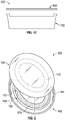
- FIGs. 1A-1C schematically illustrate a top plan view of an exemplary microwave heating construct (e.g., package or container) 100.
- the construct 100 generally includes a first component (e.g., a tray) 102 for receiving the food and a second component (e.g., a lid or cover) 104 for overlying the tray 102.
- a first component e.g., a tray
- a second component e.g., a lid or cover
- the tray 102 includes a base 106 (i.e., base panel) on which the food is to be seated, and at least one upstanding wall 108 extending upwardly from a peripheral edge 110 of the base 106.
- the base 106 and wall 108 generally extend around and define a cavity or interior space 112 for receiving a food item.
- the uppermost portion of the wall 108 may comprise a generally planar rim 114.
- the base 106 of the tray 102 and the cover 104 each include a respective microwave energy interactive element 116, 118 (shown schematically with stippling).
- the microwave energy interactive elements may each generally comprise microwave energy interactive material, such as a metal foil or high optical density material, that is operative for reflecting substantially all of impinging microwave energy. It will be noted that, in FIGs. 1A-1C , the interior side of both the tray 102 and cover 104 are shown, and the microwave energy interactive elements 116, 118 (i.e., shielding elements) are depicted as being positioned on the interior side of the tray 102 and cover 104. However, in other embodiments, either or both of microwave energy interactive elements 116, 118 may be positioned on the exterior side of the tray 102 and/or cover 104.
- microwave energy interactive elements 116, 118 may be similarly sized and shaped.
- microwave energy interactive elements 116, 118 are generally oval and annular in shape (such that the shape of the element could be described as an "oval annulus"); however, it will be appreciated that other shapes are contemplated by the present disclosure, for example, a circular annulus (i.e., ring-shaped or halo-shaped), elliptical annulus, obround annulus, etc. All of such shapes generally comprise a pair of closed curvilinear shapes that are generally concentric with one another to define the overall shape of the microwave energy interactive elements 116, 118.
- the elements 116, 118 also may be defined by and/or characterized as having a respective inner edge 120, 122 (having an inner edge length / perimeter) and a respective outer edge 124, 126 (having an outer edge length / perimeter), one or more diameters D1, D2 (only labeled on the cover 104) (e.g., major and minor diameters, a single diameter, or varying diameters, depending on the geometry of the element), an annular width W (the distance between the inner edge and the outer edge), and a thickness T (see FIG. 4 , only labeled on the cover 104).
- the inner edge 120, 122 of each element 116, 118 defines a circumscribed area A, having its own geometric properties, as will be understood by those in the art.
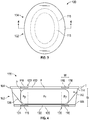
- the microwave energy interactive elements 116, 118 are positioned along the tray 102 and cover 104 to be in a substantially aligned, substantially parallel relationship when the cover 104 overlies the tray 102.
- the construct may include one or more features (not shown) that assist with the proper positioning of the first and second components (e.g., tray and cover) relative to one another.
- Such features may include, but are not limited to, a rim on the cover that fits tightly on to the tray, locking features, markings, locking contours (e.g., protrusions and corresponding depressions), and so on.
- the precise dimensions, shape, and positioning of the microwave energy interactive elements 116, 118 within the construct 100 may vary for each food heating application, depending on, for example, the dielectric property of the food at various points during the heating cycle, the density of the food being heated, the volume and mass of the food being heated, and the dimensions of the tray 102 itself.
- the microwave energy interactive elements maybe configured so that the inner edge 120, 122 of elements 116, 118 is adjacent to (and generally extends around) a portion of the food F that would be typically prone to underheating, generally a central portion Fc of the food, while elements 116, 118 are configured to overlie a portion of the food that would typically be prone to overheating, generally a peripheral portion Fp of the food. Additionally, the outer edge 124, 126 of elements 116, 118 is substantially aligned with or adjacent to an outermost periphery P of the food F.
- the food-receiving component e.g., the tray
- the food-receiving component may need to be designed with interior walls (e.g., sloped wall 128 in FIG. 4 ), contours, compartments, baffles, or other features that assist with maintaining the food item in proper alignment with elements 116, 118.
- microwave energy interactive elements 116, 118 When the microwave energy interactive elements 116, 118 are appropriately dimensioned and positioned within the construct 100 relative to the food F in the manner described above, and exposed to microwave energy, the microwave energy interactive elements 116, 118 serve two independent, but complementary (and synergistic) effects during exposure to microwave energy.
- each of the microwave energy interactive elements 116, 118 is dimensioned so that an electrical current is generated along the inner edge 120, 122 of the respective microwave energy interactive element 116, 118. In turn, an electric field is generated along the inner edge 120, 122 that provides direct heating to the adjacent, central portion Pc of the food, which would otherwise be likely to be underheated.
- microwave energy interactive elements 116, 118 reflect microwave energy away from the peripheral portion Fp of the food F, which would otherwise be likely to be overheated.
- the microwave energy interactive elements 116, 118 serve to both accelerate bulk heating near the center of the food, while shielding the outer portion of the food from being overheated.
- the microwave energy interactive elements 116, 118 may generally be dimensioned so that an inner perimeter length (the length of edge 120, 122) is approximately equal to one-quarter of the wavelength of microwave energy in the microwave oven.
- the inner perimeter length may be from about 20 mm to about 40 mm, for example, about 30 mm, and in one particular example, about 30.6 mm.
- the inner perimeter length may be from about 72 mm to about 92 mm, for example, about 82 mm, and in one particular example, about 81.97 mm.
- the inner perimeter length may be from about 163 mm to about 183 mm, for example, about 173 mm, and in one particular example, about 172.84 mm.
- the inner perimeter length may be from about 74 mm to about 94 mm, for example, about 84 mm, and in one particular example, about 83.71 mm.
- other frequencies and corresponding inner perimeter lengths are within the invention.
- the outer perimeter length (the length of edge 124, 126) of elements 116, 118 may generally be approximately one-half of the wavelength of microwave energy in the microwave oven, for example, in the case of a 2450 MHz oven, from about 50 mm to about 70 mm, for example, about 60 mm, and in one particular example, about 61.2 mm. In the case of a 915 MHz oven, the outer perimeter length may be from about 154 mm to about 174 mm, for example, about 164 mm, and in one particular example, about 163.94 mm.
- the outer perimeter length may be from about 336 mm to about 356 mm, for example, about 346 mm, and in one particular example, about 345.68 mm.
- the outer perimeter length may be from about 158 mm to about 178 mm, for example, about 168 mm, and in one particular example, about 167.42 mm.
- frequencies and corresponding outer perimeter lengths are within the invention.
- the distance or gap G ( FIG. 4 ) between elements 116, 118 may generally be from about 20 to about 40 mm, for example, about 30 mm (depending on how dense the food is; a greater gap may be used with less dense foods, which heat more evenly).
- the thickness of elements 116, 118 may be at least about 1.5 micrometers.
- the annular width W may vary, as needed to provide the proper amount of shielding.
- the annular width W may be approximately equal to one-quarter of the wavelength of microwave energy in the microwave oven, for example, from about 20 mm to about 40 mm, for example, about 30 mm, and in one particular example, about 30.6 mm.
- the construct 100 may be formed from various materials, including but not limited to, generally disposable materials such as paper, paperboard, and/or one or more polymeric materials (e.g., films, coatings, adhesives, etc.), provided that the materials are substantially resistant to softening, scorching, combusting, or degrading at typical microwave oven heating temperatures, for example, at from about 121,11 °C (250 °F) to about 218,33 °C (425 °F).
- the microwave energy interactive elements 116, 118 may be disposed on (e.g., supported on, mounted to, deposited on, or otherwise joined to) a polymer film (or other substrate) 130, 132 ( FIG.
- the polymer film including the microwave energy interactive element(s) may then be joined (adhesively or otherwise) to a dimensionally stable support comprising, for example, paperboard or a polymer / polymeric material (e.g., panel 106), so that the microwave energy interactive elements are positioned between the respective polymer film and support, and the exposed surface of the polymer film defines at least a portion of the food-contacting surface of the construct.
- the entire laminate may be thermally and/or mechanically pressed or molded (or shaped otherwise) to form the desired shape of the microwave heating construct.
- the polymer film including the microwave energy interactive element(s) may be joined (adhesively or otherwise) to a pre-shaped support.
- polymer film substrates examples include, but are not limited to, polyolefins, polyesters, polyamides, polyimides, polysulfones, polyether ketones, cellophanes, or any combination thereof.
- the polymer film comprises polyethylene terephthalate.
- the thickness of the film generally may be from about 0,142 mm (35 gauge) to about 0,254 mm (10 mil). In each of various examples, the thickness of the film may be from about 0,080 mm to about 0,0203 mm (from about 40 to about 80 gauge), from about 0,0711 mm (45 gauge) to about 0,5 mm (50 gauge), about 0,041 mm (48 gauge), or any other suitable thickness.
- Other non-conducting substrate materials such as paper and paper laminates, metal oxides, silicates, cellulosics, or any combination thereof, may also be used.
- the paperboard may have a basis weight of from about 0.0976 kg/m 2 to about 0,5371 kg/m 2 (from about 60 to about 330 lbs/ream (lbs/3000 sq. ft.), for example, from about 0,1302 to about 0,2278 kg/m 2 (from about 80 to about 140 lbs/ream).
- the paperboard generally may have a thickness of from about 0,1524 mm to about 0,762 mm (from about 6 to about 30 mils), for example, from about 0,3048 mm to about 0,7112 mm (from about 12 to 28 mils). In one particular example, the paperboard has a thickness of about 0,3048 mm (12 mils).
- Any suitable paperboard may be used, for example, a solid bleached or solid unbleached sulfate board, such as SUS® board, commercially available from Graphic Packaging International.
- the support may also comprise a polymeric material, for example, crystalline polyethylene terephthalate (CPET) or other suitable material.
- CPET crystalline polyethylene terephthalate
- the construct may include one or more other microwave energy interactive elements, for example, a susceptor.
- a susceptor is a thin layer of microwave interactive material (generally less than about 100 angstroms in thickness, for example, from about 60 to about 100 angstroms in thickness, and having an optical density of from about 0.15 to about 0.35, for example, about 0.21 to about 0.28) that tends to absorb at least a portion of impinging microwave energy and convert it to thermal energy (i.e., heat) at the interface with a food item.
- Such elements often are used to promote browning and/or crisping of the surface of a food item.
- Other elements may comprise segmented foils that direct microwave energy to certain parts of the food item, arrays of reflective elements that can be tailored to affect bulk heating rates, and so on.
- the microwave heating constructs of the present disclosure may have any suitable shape, dimensions, combination of microwave energy interactive elements, and so on.
- other constructs may have the shape of a circle, obround, triangle, square, rectangle, pentagon, hexagon, heptagon, octagon, or any other suitable regular or irregular shape.
- Such constructs may have no distinct corners (e.g., as with a circle, which may be characterized as having no distinct corners or as comprising a continuous arrangement of corners), or may have one or more distinct corners, as with a triangle, square, or numerous other shapes.
- any of such corners may be rounded in shape, and the degree of rounding (i.e., the radius of curvature) may vary for each application.
- any of such constructs may have any suitable number of walls between the corners, and such walls may be substantially straight, curved, or any combination thereof.
- the present disclosure details a construct comprising a pair of opposed disks, a pair of opposed trays (with one tray serving as the cover for the other), integral components (e.g., hinged to one another), constructs in which the first and second components are similar in size or shape, constructs in which the first and second components differ in size or shape, and so on.
- the first container included no microwave energy interactive material.
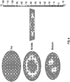
- the second container included a pair of annular microwave energy shielding elements (as would be, for example, joined to a tray and cover), as described above and generally shown in FIGs. 5A-5D (dimensions in mm).
- the initial temperature of the food was -10°C and the microwave power was set at 1250 watts.
- the heating time was 5 minutes.
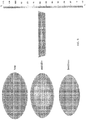
- the dimensions of the heating space were based on those of a Panasonic NN-SN942 microwave oven.
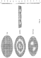
- FIG. 6 the geometric center of the control container was heated to a lower temperature than the peripheral areas. The lowest temperature in this region was about 25°C. A significant improvement was seen in heating uniformity using the experimental container, as shown in FIG. 7 , with the geometric center of the container reaching a substantially uniform temperature of about 90-100°C.
- FIG. 8 is a color version of FIG. 6 and illustrates the temperature profile of food heated in a container without microwave energy interactive elements, generated using computer modeling.
- FIG. 9 is a color version of FIG. 7 and illustrates the temperature profile of food heated in a container with microwave energy interactive elements according to FIGs. 5A-5D , generated using computer modeling.
Description
- This application claims the benefit of
U.S. Provisional Patent Application No. 62/282,794 filed August 11, 2015 - Microwave ovens commonly are used as a convenient means of heating food items. However, when larger food items are heated in a microwave oven, some portions of the food may tend to reach the desired final heating temperature too early in the heating cycle and become dry or charred, while other portions remain underheated or even cold. Thus, there is a need for a package, container, or other construct that controls the rate of heating of the food item so that the food item is suitably and substantially uniformly heated at the end of the heating cycle.
- Prior art document
EP0206811 discloses a microwave heating construct comprising: a tray including at least one upstanding wall extending upwardly from a base; the base and the wall of the tray defining a cavity for receiving a food item; a cover; at least a first microwave energy interactive element on the tray; wherein the at least first microwave energy interactive element is dimensioned and arranged to extend along a peripheral region of the food item; wherein the at least first microwave energy interactive element reduces heating along the peripheral region of the food item when the at least first microwave energy interactive element is exposed to microwave energy. - The invention is achieved with a microwave heating construct (e.g., package, container, etc.) according to
claim 1, and a method of heating according to claim 6. Dependent claims correspond to preferred embodiments of the invention. - The description refers to the accompanying drawings in which like reference characters refer to like parts throughout the several views, and in which:
-
FIGs. 1A-1C schematically illustrate a top plan view of an exemplary microwave heating construct according to the present disclosure, including a tray and cover (interior side of each shown); -
FIG. 2 schematically illustrates the microwave heating construct ofFIG. 1 , in a partially assembled (i.e., closed) configuration; -
FIG. 3 schematically illustrates the microwave heating construct ofFIG. 1 , in a fully assembled (i.e., closed) configuration with the cover overlying the tray; -
FIG. 4 schematically illustrates a cross-sectional view of the microwave heating construct ofFIG. 3 , taken along a line 4-4; -
FIGs. 5A-5D schematically illustrate one configuration of exemplary microwave energy interactive elements according to the disclosure, used in the computer modeling of microwave heating of food in containers; -
FIG. 6 illustrates the temperature profile of food heated in a container without microwave energy interactive elements, generated using computer modeling; and -
FIG. 7 illustrates the temperature profile of food heated in a container with microwave energy interactive elements according toFIGs. 5A-5D , generated using computer modeling. -
FIG. 8 is a color version ofFIG. 6 and illustrates the temperature profile of food heated in a container without microwave energy interactive elements, generated using computer modeling; and -
FIG. 9 is a color version ofFIG. 7 and illustrates the temperature profile of food heated in a container with microwave energy interactive elements according toFIG. 5A-5D , generated using computer modeling. - Various aspects of the disclosure may be illustrated by referring to the figures, in which like numerals refer to like components. It will be understood that although particular examples of microwave heating constructs are shown herein, the teachings of the present disclosure may be used with numerous other constructs in accordance with the principles described herein.
-
FIGs. 1A-1C schematically illustrate a top plan view of an exemplary microwave heating construct (e.g., package or container) 100. Theconstruct 100 generally includes a first component (e.g., a tray) 102 for receiving the food and a second component (e.g., a lid or cover) 104 for overlying thetray 102. - In the illustrated embodiment, the
tray 102 includes a base 106 (i.e., base panel) on which the food is to be seated, and at least oneupstanding wall 108 extending upwardly from aperipheral edge 110 of thebase 106. Thebase 106 andwall 108 generally extend around and define a cavity orinterior space 112 for receiving a food item. The uppermost portion of thewall 108 may comprise a generallyplanar rim 114. - The
base 106 of thetray 102 and thecover 104 each include a respective microwave energyinteractive element 116, 118 (shown schematically with stippling). The microwave energy interactive elements may each generally comprise microwave energy interactive material, such as a metal foil or high optical density material, that is operative for reflecting substantially all of impinging microwave energy. It will be noted that, inFIGs. 1A-1C , the interior side of both thetray 102 andcover 104 are shown, and the microwave energyinteractive elements 116, 118 (i.e., shielding elements) are depicted as being positioned on the interior side of thetray 102 andcover 104. However, in other embodiments, either or both of microwave energyinteractive elements tray 102 and/orcover 104. - As shown in
FIGs. 1A-1C , the microwave energyinteractive elements interactive elements interactive elements - The
elements inner edge 120, 122 (having an inner edge length / perimeter) and a respectiveouter edge 124, 126 (having an outer edge length / perimeter), one or more diameters D1, D2 (only labeled on the cover 104) (e.g., major and minor diameters, a single diameter, or varying diameters, depending on the geometry of the element), an annular width W (the distance between the inner edge and the outer edge), and a thickness T (seeFIG. 4 , only labeled on the cover 104). Theinner edge element - As shown in
FIG. 2 (schematically depictingcover 104 partially positioned over tray 102),FIG. 3 (schematically depicting in top plan view thecover 104 positioned ontray 102, hidden from view), andFIG. 4 (schematically depicting the cross section only of thetray 102 /cover 104 configuration ofFIG. 3 taken along a line 4-4), the microwave energyinteractive elements tray 102 andcover 104 to be in a substantially aligned, substantially parallel relationship when thecover 104 overlies thetray 102. It is therefore contemplated that the construct may include one or more features (not shown) that assist with the proper positioning of the first and second components (e.g., tray and cover) relative to one another. Such features may include, but are not limited to, a rim on the cover that fits tightly on to the tray, locking features, markings, locking contours (e.g., protrusions and corresponding depressions), and so on. - The precise dimensions, shape, and positioning of the microwave energy
interactive elements construct 100 may vary for each food heating application, depending on, for example, the dielectric property of the food at various points during the heating cycle, the density of the food being heated, the volume and mass of the food being heated, and the dimensions of thetray 102 itself. - As best seen in
FIG. 4 , in general, the microwave energy interactive elements maybe configured so that theinner edge elements elements outer edge elements wall 128 inFIG. 4 ), contours, compartments, baffles, or other features that assist with maintaining the food item in proper alignment withelements - When the microwave energy
interactive elements construct 100 relative to the food F in the manner described above, and exposed to microwave energy, the microwave energyinteractive elements - First, each of the microwave energy
interactive elements inner edge interactive element inner edge interactive elements interactive elements - To achieve these beneficial, synergistic effects, the microwave energy
interactive elements edge 120, 122) is approximately equal to one-quarter of the wavelength of microwave energy in the microwave oven. For example, in the case of a 2450 MHz oven, the inner perimeter length may be from about 20 mm to about 40 mm, for example, about 30 mm, and in one particular example, about 30.6 mm. In the case of a 915 MHz oven, the inner perimeter length may be from about 72 mm to about 92 mm, for example, about 82 mm, and in one particular example, about 81.97 mm. In the case of a 433.92 MHz oven, the inner perimeter length may be from about 163 mm to about 183 mm, for example, about 173 mm, and in one particular example, about 172.84 mm. In the case of an 896 MHz oven, the inner perimeter length may be from about 74 mm to about 94 mm, for example, about 84 mm, and in one particular example, about 83.71 mm. However, other frequencies and corresponding inner perimeter lengths are within the invention. - The outer perimeter length (the length of
edge 124, 126) ofelements - Additionally, the distance or gap G (
FIG. 4 ) betweenelements elements - The annular width W may vary, as needed to provide the proper amount of shielding. For example, the annular width W may be approximately equal to one-quarter of the wavelength of microwave energy in the microwave oven, for example, from about 20 mm to about 40 mm, for example, about 30 mm, and in one particular example, about 30.6 mm.
- The
construct 100 may be formed from various materials, including but not limited to, generally disposable materials such as paper, paperboard, and/or one or more polymeric materials (e.g., films, coatings, adhesives, etc.), provided that the materials are substantially resistant to softening, scorching, combusting, or degrading at typical microwave oven heating temperatures, for example, at from about 121,11 °C (250 °F) to about 218,33 °C (425 °F). For example, the microwave energyinteractive elements FIG. 4 ) for ease of handling and/or to prevent contact between the microwave energy interactive material and the food item. The polymer film including the microwave energy interactive element(s) may then be joined (adhesively or otherwise) to a dimensionally stable support comprising, for example, paperboard or a polymer / polymeric material (e.g., panel 106), so that the microwave energy interactive elements are positioned between the respective polymer film and support, and the exposed surface of the polymer film defines at least a portion of the food-contacting surface of the construct. The entire laminate may be thermally and/or mechanically pressed or molded (or shaped otherwise) to form the desired shape of the microwave heating construct. Alternatively, the polymer film including the microwave energy interactive element(s) may be joined (adhesively or otherwise) to a pre-shaped support. - Examples of polymer film substrates that may be suitable include, but are not limited to, polyolefins, polyesters, polyamides, polyimides, polysulfones, polyether ketones, cellophanes, or any combination thereof. In one particular example, the polymer film comprises polyethylene terephthalate. The thickness of the film generally may be from about 0,142 mm (35 gauge) to about 0,254 mm (10 mil). In each of various examples, the thickness of the film may be from about 0,080 mm to about 0,0203 mm (from about 40 to about 80 gauge), from about 0,0711 mm (45 gauge) to about 0,5 mm (50 gauge), about 0,041 mm (48 gauge), or any other suitable thickness. Other non-conducting substrate materials such as paper and paper laminates, metal oxides, silicates, cellulosics, or any combination thereof, may also be used.
- Where paperboard is used as the dimensionally stable support, the paperboard may have a basis weight of from about 0.0976 kg/m2 to about 0,5371 kg/m2 (from about 60 to about 330 lbs/ream (lbs/3000 sq. ft.), for example, from about 0,1302 to about 0,2278 kg/m2 (from about 80 to about 140 lbs/ream). The paperboard generally may have a thickness of from about 0,1524 mm to about 0,762 mm (from about 6 to about 30 mils), for example, from about 0,3048 mm to about 0,7112 mm (from about 12 to 28 mils). In one particular example, the paperboard has a thickness of about 0,3048 mm (12 mils). Any suitable paperboard may be used, for example, a solid bleached or solid unbleached sulfate board, such as SUS® board, commercially available from Graphic Packaging International. The support may also comprise a polymeric material, for example, crystalline polyethylene terephthalate (CPET) or other suitable material.
- The construct may include one or more other microwave energy interactive elements, for example, a susceptor. A susceptor is a thin layer of microwave interactive material (generally less than about 100 angstroms in thickness, for example, from about 60 to about 100 angstroms in thickness, and having an optical density of from about 0.15 to about 0.35, for example, about 0.21 to about 0.28) that tends to absorb at least a portion of impinging microwave energy and convert it to thermal energy (i.e., heat) at the interface with a food item. Such elements often are used to promote browning and/or crisping of the surface of a food item. Other elements may comprise segmented foils that direct microwave energy to certain parts of the food item, arrays of reflective elements that can be tailored to affect bulk heating rates, and so on.
- Although only specific embodiments are described herein, the microwave heating constructs of the present disclosure may have any suitable shape, dimensions, combination of microwave energy interactive elements, and so on. For example, although a somewhat elongate or oval construct with rounded ends is illustrated, other constructs may have the shape of a circle, obround, triangle, square, rectangle, pentagon, hexagon, heptagon, octagon, or any other suitable regular or irregular shape. Such constructs may have no distinct corners (e.g., as with a circle, which may be characterized as having no distinct corners or as comprising a continuous arrangement of corners), or may have one or more distinct corners, as with a triangle, square, or numerous other shapes. Any of such corners may be rounded in shape, and the degree of rounding (i.e., the radius of curvature) may vary for each application. Likewise, any of such constructs may have any suitable number of walls between the corners, and such walls may be substantially straight, curved, or any combination thereof. Thus, the present disclosure details a construct comprising a pair of opposed disks, a pair of opposed trays (with one tray serving as the cover for the other), integral components (e.g., hinged to one another), constructs in which the first and second components are similar in size or shape, constructs in which the first and second components differ in size or shape, and so on.
- Computer modeling was used to simulate the microwave heating of food in two containers. The first container (control container) included no microwave energy interactive material. The second container (experimental container) included a pair of annular microwave energy shielding elements (as would be, for example, joined to a tray and cover), as described above and generally shown in
FIGs. 5A-5D (dimensions in mm). The initial temperature of the food was -10°C and the microwave power was set at 1250 watts. The heating time was 5 minutes. The dimensions of the heating space were based on those of a Panasonic NN-SN942 microwave oven. - As shown in
FIG. 6 , the geometric center of the control container was heated to a lower temperature than the peripheral areas. The lowest temperature in this region was about 25°C. A significant improvement was seen in heating uniformity using the experimental container, as shown inFIG. 7 , with the geometric center of the container reaching a substantially uniform temperature of about 90-100°C.FIG. 8 is a color version ofFIG. 6 and illustrates the temperature profile of food heated in a container without microwave energy interactive elements, generated using computer modeling.FIG. 9 is a color version ofFIG. 7 and illustrates the temperature profile of food heated in a container with microwave energy interactive elements according toFIGs. 5A-5D , generated using computer modeling.
Claims (15)
- A microwave heating construct (100) for heating a food item (F) in a microwave oven using microwave energy of a given wavelength comprising:a tray (102) including at least one upstanding wall (108) extending upwardly from a base (106); the base (106) and the wall (108) of the tray (102) defining a cavity (112) for receiving a food item (F);a cover (104);at least a first microwave energy interactive element (116) on the tray (102), the base (106) of the tray (102) including the first microwave energy interactive element (116), the cover (104) including at least a second microwave energy interactive element (118), the first microwave energy interactive element (116) being annular in shape and having an inner edge (120) and an outer edge (124), wherein with the cover (104) disposed over the tray (102), the first microwave energy interactive element (116) and the second microwave energy interactive element (118) are in an aligned relationship in the cavity (112);wherein the first microwave energy interactive element (116) is dimensioned and arranged to extend along a peripheral region (Fp) of the food item (F) received in the central portion of the cavity (112), the first microwave energy interactive element (116) is dimensioned and positioned within the construct (100) relative to the food item (F) received in the central portion of the cavity (112) so that when the first microwave energy interactive element (116) is exposed to microwave energy of a given wavelength an electrical current is generated along the inner edge (120) and, in turn, an electric field is generated along the inner edge (120) that provides direct heating to the adjacent food item (F) received in the central portion of the cavity (112), and the first microwave energy interactive element (116) has an inner perimeter length approximately equal to one-quarter of the wavelength of the microwave energy used in the microwave oven in which the construct (100) is heated;wherein the first microwave energy interactive element (116) and the second microwave energy interactive element (118) reduce heating along the peripheral region (Fp) of the food item (F) received in the central portion of the cavity (112), when the first microwave energy interactive element (116) is exposed to microwave energy.
- The microwave heating construct (100) of claim 1 wherein, with the cover (104) disposed over the tray (102), the first microwave energy interactive element (116) and the second microwave energy interactive element (118) are opposite one another in the cavity (112).
- The microwave heating construct (100) of claim 1 wherein the wall (108) includes a generally planar rim (114).
- The microwave heating construct (100) of claim 1 wherein heating of a central portion (Fc) of the food item (F) received in the central portion of the cavity (112) is enhanced and heating of the peripheral region (Fp) of the food item (F) received in the central portion of the cavity (112) is reduced by the first microwave energy interactive element (116) and the second microwave energy interactive element (118).
- The microwave heating construct (100) of claim 1 wherein the second microwave energy interactive element (118) has an inner perimeter length approximately equal to one-quarter of a wavelength of the microwave energy in a microwave oven in which the construct (100) is heated.
- A method of heating a food item (F) in a microwave oven with a microwave heating construct according to any of the previous claims using microwave energy of a given wavelength comprising:obtaining a microwave heating construct (100) comprising:a tray (102) including at least one upstanding wall (108) extending upwardly from a base (106); the base (106) and the wall (108) of the tray (102) defining a cavity (112) for receiving a food item (F);a cover (104);at least a first microwave energy interactive element (116) on the tray (102), the base (106) of the tray (102) including the first microwave energy interactive element (116);wherein the first microwave energy interactive element (116) is dimensioned and arranged to extend along a peripheral region (Fp) of the food item (F) received in the central portion of the cavity (112), the first microwave energy interactive element (116) has an inner perimeter length approximately equal to one-quarter of the wavelength of the microwave energy used in a microwave oven in which the construct (100) is heated, and an outer perimeter length of the first microwave energy interactive element (116) is approximately one-half of the wavelength of the microwave energy used in the microwave oven;heating the microwave heating construct (100);wherein the first microwave energy interactive element (116) reduces heating along the peripheral region (Fp) of the food item (F) received in the central portion of the cavity (112), when the first microwave energy interactive element (116) is exposed to microwave energy.
- The method of heating of claim 6 wherein the cover (104) includes a second microwave energy interactive element (118).
- The method of heating of claim 7 wherein, with the cover (104) disposed over the tray (102), the first microwave energy interactive element (116) and the second microwave energy interactive element (118) are opposite one another in the cavity (112).
- The method of heating of claim 7 wherein, with the cover (104) disposed over the tray (102), the first microwave energy interactive element (116) and the second microwave energy interactive element (118) are in an aligned relationship in the cavity (112).
- The method of heating of claim 7 wherein the wall (108) includes a generally planar rim (114).
- The method of heating of claim 10 wherein heating of a central portion (Fc) of the food item (F) received in the central portion of the cavity (112) is enhanced and heating of the peripheral region (Fp) of the food item (F) received in the central portion of the cavity (112) is reduced by the first microwave energy interactive element (116) and the second microwave energy interactive element (118).
- The method of heating of claim 7 wherein the second microwave energy interactive element (11 8) has an inner perimeter length approximately equal to one-quarter of a wavelength of the microwave energy in a microwave oven in which the construct (100) is heated.
- The method of heating of claim 10 wherein heating of a central portion (Fc) of the food item (F) received in the central portion of the cavity (112) is enhanced and heating of the peripheral region (Fp) of the food item received in the central portion of the cavity (112) is reduced by the first microwave energy interactive element (116).
- The microwave heating construct (100) of claim 1 wherein the second microwave energy interactive element (118) has an inner edge (122) and an outer edge (126), and the outer edges (124, 126) of the first microwave energy interactive element (116) and the second microwave energy interactive element (118) are substantially aligned with an outermost periphery (P) of the food item (F) received in the central portion of the cavity (112).
- The method of heating of claim 7, wherein the first microwave energy interactive element (116) and the second microwave energy interactive element (118) have respective inner edges (120, 122) and respective outer edges (124, 126), and the outer edges (124, 126) of the first microwave energy interactive element (116) and the second microwave energy interactive element (118) are substantially aligned with an outermost periphery (P) of the food item (F) received in the central portion of the cavity (112).
Applications Claiming Priority (2)
| Application Number | Priority Date | Filing Date | Title |
|---|---|---|---|
| US201562282794P | 2015-08-11 | 2015-08-11 | |
| PCT/US2016/045746 WO2017027364A1 (en) | 2015-08-11 | 2016-08-05 | Microwave heating package with polarized shield |
Publications (3)
| Publication Number | Publication Date |
|---|---|
| EP3334663A1 EP3334663A1 (en) | 2018-06-20 |
| EP3334663A4 EP3334663A4 (en) | 2019-04-17 |
| EP3334663B1 true EP3334663B1 (en) | 2020-07-08 |
Family
ID=57984043
Family Applications (1)
| Application Number | Title | Priority Date | Filing Date |
|---|---|---|---|
| EP16835688.9A Active EP3334663B1 (en) | 2015-08-11 | 2016-08-05 | Microwave heating package with polarized shield |
Country Status (7)
| Country | Link |
|---|---|
| US (1) | US10364085B2 (en) |
| EP (1) | EP3334663B1 (en) |
| BR (1) | BR112018002019B1 (en) |
| CA (1) | CA2992478C (en) |
| ES (1) | ES2817753T3 (en) |
| MX (1) | MX2018001643A (en) |
| WO (1) | WO2017027364A1 (en) |
Families Citing this family (7)
| Publication number | Priority date | Publication date | Assignee | Title |
|---|---|---|---|---|
| US9301345B2 (en) | 2012-03-14 | 2016-03-29 | Microwave Materials Technologies, Inc. | Determination of a heating profile for a large-scale microwave heating system |
| EP3341960A4 (en) | 2015-10-01 | 2019-09-25 | 915 Labs, LLC | Arrangement of articles in a carrier for microwave heating |
| KR20190094340A (en) | 2016-10-03 | 2019-08-13 | 915 랩스, 엘엘씨 | Transport line carrier for microwave heating |
| BR112019019114A2 (en) | 2017-03-15 | 2020-04-14 | 915 Labs Llc | microwave control elements for enhanced heating of packaged items |
| CA3056407A1 (en) | 2017-03-15 | 2018-09-20 | 915 Labs, LLC | Multi-pass microwave heating system |
| BR112019020223A2 (en) | 2017-04-17 | 2020-04-22 | 915 Labs Llc | microwave assisted sterilization and pasteurization system using synergistic packaging configurations, conveyors and launchers |
| US10708986B2 (en) * | 2018-05-01 | 2020-07-07 | Dart Industries Inc. | Device for and method of microwave heating with inversion |
Family Cites Families (20)
| Publication number | Priority date | Publication date | Assignee | Title |
|---|---|---|---|---|
| CA1239999A (en) * | 1985-06-25 | 1988-08-02 | Richard M. Keefer | Microwave container and package comprising said container and a body of material to be heated, and method of making same |
| US5310980A (en) | 1988-11-28 | 1994-05-10 | Beckett Industries, Inc. | Control of microwave energy in cooking foodstuffs |
| US5424517A (en) * | 1993-10-27 | 1995-06-13 | James River Paper Company, Inc. | Microwave impedance matching film for microwave cooking |
| US5593610A (en) * | 1995-08-04 | 1997-01-14 | Hormel Foods Corporation | Container for active microwave heating |
| DE69634455T2 (en) * | 1995-09-18 | 2006-02-02 | Graphic Packaging International, Inc., Golden | Microwaveable container |
| US6150646A (en) | 1996-08-26 | 2000-11-21 | Graphic Packaging Corporation | Microwavable container having active microwave energy heating elements for combined bulk and surface heating |
| CA2196154A1 (en) * | 1997-01-28 | 1998-07-28 | Lawrence Lai | Strip-line microwave structure |
| US6717121B2 (en) | 2001-09-28 | 2004-04-06 | Graphic Packaging International, Inc. | Patterned microwave susceptor element and microwave container incorporating same |
| US6777655B2 (en) | 2002-04-09 | 2004-08-17 | Nestec S.A. | Uniform microwave heating of food in a container |
| ES2388716T3 (en) | 2002-10-08 | 2012-10-17 | Graphic Packaging International, Inc. | Method and tool for the formation of a container having a flange or other encapsulated conformation, or formed of an injection molded material. |
| CN101636620B (en) | 2007-01-22 | 2013-04-24 | 印刷包装国际公司 | Even heating microwavable container |
| EP2152604B1 (en) | 2007-05-01 | 2012-06-06 | Nestec S.A. | Packaging for microwave preparation of cookies |
| EP2139787A4 (en) | 2007-05-01 | 2011-05-25 | Graphic Packaging Int Inc | Package for heating a food product |
| CA2937567C (en) | 2007-05-15 | 2019-06-04 | Graphic Packaging International, Inc. | Microwavable construct with contoured heating surface |
| US20100003835A1 (en) * | 2008-07-03 | 2010-01-07 | American Air Liquide, Inc. | Low-K Precursors Based on Silicon Cryptands, Crown Ethers and Podands |
| EP2296999B1 (en) * | 2008-07-11 | 2014-03-05 | Graphic Packaging International, Inc. | Microwave heating container |
| ES2414207T3 (en) * | 2008-08-14 | 2013-07-18 | Graphic Packaging International, Inc. | Packaging structure for microwave heating, with lifting bottom |
| US20100078428A1 (en) | 2008-09-30 | 2010-04-01 | Berry Plastics Corporation | Microwavable food package |
| JP2014501667A (en) | 2010-11-12 | 2014-01-23 | グラフィック パッケージング インターナショナル インコーポレイテッド | Container, forming tool, and method of forming container |
| EP3003903B1 (en) * | 2013-06-03 | 2019-09-18 | Graphic Packaging International, LLC | Container with window and microwave energy interactive material |
-
2016
- 2016-08-05 MX MX2018001643A patent/MX2018001643A/en unknown
- 2016-08-05 US US15/229,512 patent/US10364085B2/en active Active
- 2016-08-05 EP EP16835688.9A patent/EP3334663B1/en active Active
- 2016-08-05 ES ES16835688T patent/ES2817753T3/en active Active
- 2016-08-05 CA CA2992478A patent/CA2992478C/en active Active
- 2016-08-05 BR BR112018002019-2A patent/BR112018002019B1/en active IP Right Grant
- 2016-08-05 WO PCT/US2016/045746 patent/WO2017027364A1/en active Application Filing
Non-Patent Citations (1)
| Title |
|---|
| None * |
Also Published As
| Publication number | Publication date |
|---|---|
| CA2992478C (en) | 2021-10-26 |
| EP3334663A4 (en) | 2019-04-17 |
| US20170043936A1 (en) | 2017-02-16 |
| WO2017027364A1 (en) | 2017-02-16 |
| EP3334663A1 (en) | 2018-06-20 |
| BR112018002019A2 (en) | 2018-09-18 |
| MX2018001643A (en) | 2018-05-17 |
| CA2992478A1 (en) | 2017-02-16 |
| BR112018002019B1 (en) | 2022-03-15 |
| US10364085B2 (en) | 2019-07-30 |
| ES2817753T3 (en) | 2021-04-08 |
Similar Documents
| Publication | Publication Date | Title |
|---|---|---|
| EP3334663B1 (en) | Microwave heating package with polarized shield | |
| US8901469B2 (en) | Method and apparatus for cooking raw food items in a microwave oven | |
| JP5055381B2 (en) | Container that can be heated evenly by microwave | |
| CA2715627C (en) | Apparatus for preparing a food item in a microwave oven | |
| EP2974973B1 (en) | Microwavable construct with contoured heating surface | |
| US20140348989A1 (en) | Package for Combined Steam and Microwave Heating of Food | |
| JP5693517B2 (en) | Structure with undulating heating surface usable in microwave oven and method using the structure | |
| EP2510285B1 (en) | Deep dish microwave heating construct | |
| EP2507558B1 (en) | Microwave heating construct with venting features | |
| US20180170653A1 (en) | Microwave Packaging | |
| JP2013545513A (en) | Apparatus for microwave heating for curved foods |
Legal Events
| Date | Code | Title | Description |
|---|---|---|---|
| STAA | Information on the status of an ep patent application or granted ep patent |
Free format text: STATUS: THE INTERNATIONAL PUBLICATION HAS BEEN MADE |
|
| PUAI | Public reference made under article 153(3) epc to a published international application that has entered the european phase |
Free format text: ORIGINAL CODE: 0009012 |
|
| STAA | Information on the status of an ep patent application or granted ep patent |
Free format text: STATUS: REQUEST FOR EXAMINATION WAS MADE |
|
| 17P | Request for examination filed |
Effective date: 20180306 |
|
| AK | Designated contracting states |
Kind code of ref document: A1 Designated state(s): AL AT BE BG CH CY CZ DE DK EE ES FI FR GB GR HR HU IE IS IT LI LT LU LV MC MK MT NL NO PL PT RO RS SE SI SK SM TR |
|
| AX | Request for extension of the european patent |
Extension state: BA ME |
|
| DAV | Request for validation of the european patent (deleted) | ||
| DAX | Request for extension of the european patent (deleted) | ||
| A4 | Supplementary search report drawn up and despatched |
Effective date: 20190320 |
|
| RIC1 | Information provided on ipc code assigned before grant |
Ipc: A47J 36/02 20060101ALI20190314BHEP Ipc: H05B 6/64 20060101ALI20190314BHEP Ipc: B65D 81/34 20060101AFI20190314BHEP Ipc: B65D 77/20 20060101ALI20190314BHEP Ipc: B65D 1/34 20060101ALI20190314BHEP |
|
| RIC1 | Information provided on ipc code assigned before grant |
Ipc: B65D 81/34 20060101AFI20191217BHEP Ipc: B65D 77/20 20060101ALI20191217BHEP Ipc: A47J 36/02 20060101ALI20191217BHEP Ipc: B65D 1/34 20060101ALI20191217BHEP Ipc: H05B 6/64 20060101ALI20191217BHEP |
|
| GRAP | Despatch of communication of intention to grant a patent |
Free format text: ORIGINAL CODE: EPIDOSNIGR1 |
|
| STAA | Information on the status of an ep patent application or granted ep patent |
Free format text: STATUS: GRANT OF PATENT IS INTENDED |
|
| INTG | Intention to grant announced |
Effective date: 20200203 |
|
| GRAS | Grant fee paid |
Free format text: ORIGINAL CODE: EPIDOSNIGR3 |
|
| GRAA | (expected) grant |
Free format text: ORIGINAL CODE: 0009210 |
|
| STAA | Information on the status of an ep patent application or granted ep patent |
Free format text: STATUS: THE PATENT HAS BEEN GRANTED |
|
| AK | Designated contracting states |
Kind code of ref document: B1 Designated state(s): AL AT BE BG CH CY CZ DE DK EE ES FI FR GB GR HR HU IE IS IT LI LT LU LV MC MK MT NL NO PL PT RO RS SE SI SK SM TR |
|
| REG | Reference to a national code |
Ref country code: AT Ref legal event code: REF Ref document number: 1288222 Country of ref document: AT Kind code of ref document: T Effective date: 20200715 Ref country code: CH Ref legal event code: EP |
|
| REG | Reference to a national code |
Ref country code: DE Ref legal event code: R096 Ref document number: 602016039713 Country of ref document: DE |
|
| REG | Reference to a national code |
Ref country code: IE Ref legal event code: FG4D |
|
| REG | Reference to a national code |
Ref country code: NL Ref legal event code: FP |
|
| REG | Reference to a national code |
Ref country code: LT Ref legal event code: MG4D |
|
| REG | Reference to a national code |
Ref country code: AT Ref legal event code: MK05 Ref document number: 1288222 Country of ref document: AT Kind code of ref document: T Effective date: 20200708 |
|
| PG25 | Lapsed in a contracting state [announced via postgrant information from national office to epo] |
Ref country code: PT Free format text: LAPSE BECAUSE OF FAILURE TO SUBMIT A TRANSLATION OF THE DESCRIPTION OR TO PAY THE FEE WITHIN THE PRESCRIBED TIME-LIMIT Effective date: 20201109 Ref country code: BG Free format text: LAPSE BECAUSE OF FAILURE TO SUBMIT A TRANSLATION OF THE DESCRIPTION OR TO PAY THE FEE WITHIN THE PRESCRIBED TIME-LIMIT Effective date: 20201008 Ref country code: SE Free format text: LAPSE BECAUSE OF FAILURE TO SUBMIT A TRANSLATION OF THE DESCRIPTION OR TO PAY THE FEE WITHIN THE PRESCRIBED TIME-LIMIT Effective date: 20200708 Ref country code: GR Free format text: LAPSE BECAUSE OF FAILURE TO SUBMIT A TRANSLATION OF THE DESCRIPTION OR TO PAY THE FEE WITHIN THE PRESCRIBED TIME-LIMIT Effective date: 20201009 Ref country code: FI Free format text: LAPSE BECAUSE OF FAILURE TO SUBMIT A TRANSLATION OF THE DESCRIPTION OR TO PAY THE FEE WITHIN THE PRESCRIBED TIME-LIMIT Effective date: 20200708 Ref country code: NO Free format text: LAPSE BECAUSE OF FAILURE TO SUBMIT A TRANSLATION OF THE DESCRIPTION OR TO PAY THE FEE WITHIN THE PRESCRIBED TIME-LIMIT Effective date: 20201008 Ref country code: AT Free format text: LAPSE BECAUSE OF FAILURE TO SUBMIT A TRANSLATION OF THE DESCRIPTION OR TO PAY THE FEE WITHIN THE PRESCRIBED TIME-LIMIT Effective date: 20200708 Ref country code: LT Free format text: LAPSE BECAUSE OF FAILURE TO SUBMIT A TRANSLATION OF THE DESCRIPTION OR TO PAY THE FEE WITHIN THE PRESCRIBED TIME-LIMIT Effective date: 20200708 Ref country code: HR Free format text: LAPSE BECAUSE OF FAILURE TO SUBMIT A TRANSLATION OF THE DESCRIPTION OR TO PAY THE FEE WITHIN THE PRESCRIBED TIME-LIMIT Effective date: 20200708 |
|
| PG25 | Lapsed in a contracting state [announced via postgrant information from national office to epo] |
Ref country code: IS Free format text: LAPSE BECAUSE OF FAILURE TO SUBMIT A TRANSLATION OF THE DESCRIPTION OR TO PAY THE FEE WITHIN THE PRESCRIBED TIME-LIMIT Effective date: 20201108 Ref country code: RS Free format text: LAPSE BECAUSE OF FAILURE TO SUBMIT A TRANSLATION OF THE DESCRIPTION OR TO PAY THE FEE WITHIN THE PRESCRIBED TIME-LIMIT Effective date: 20200708 Ref country code: LV Free format text: LAPSE BECAUSE OF FAILURE TO SUBMIT A TRANSLATION OF THE DESCRIPTION OR TO PAY THE FEE WITHIN THE PRESCRIBED TIME-LIMIT Effective date: 20200708 Ref country code: PL Free format text: LAPSE BECAUSE OF FAILURE TO SUBMIT A TRANSLATION OF THE DESCRIPTION OR TO PAY THE FEE WITHIN THE PRESCRIBED TIME-LIMIT Effective date: 20200708 |
|
| REG | Reference to a national code |
Ref country code: CH Ref legal event code: PL |
|
| REG | Reference to a national code |
Ref country code: ES Ref legal event code: FG2A Ref document number: 2817753 Country of ref document: ES Kind code of ref document: T3 Effective date: 20210408 |
|
| REG | Reference to a national code |
Ref country code: DE Ref legal event code: R097 Ref document number: 602016039713 Country of ref document: DE |
|
| PG25 | Lapsed in a contracting state [announced via postgrant information from national office to epo] |
Ref country code: IT Free format text: LAPSE BECAUSE OF FAILURE TO SUBMIT A TRANSLATION OF THE DESCRIPTION OR TO PAY THE FEE WITHIN THE PRESCRIBED TIME-LIMIT Effective date: 20200708 Ref country code: EE Free format text: LAPSE BECAUSE OF FAILURE TO SUBMIT A TRANSLATION OF THE DESCRIPTION OR TO PAY THE FEE WITHIN THE PRESCRIBED TIME-LIMIT Effective date: 20200708 Ref country code: SM Free format text: LAPSE BECAUSE OF FAILURE TO SUBMIT A TRANSLATION OF THE DESCRIPTION OR TO PAY THE FEE WITHIN THE PRESCRIBED TIME-LIMIT Effective date: 20200708 Ref country code: LU Free format text: LAPSE BECAUSE OF NON-PAYMENT OF DUE FEES Effective date: 20200805 Ref country code: LI Free format text: LAPSE BECAUSE OF NON-PAYMENT OF DUE FEES Effective date: 20200831 Ref country code: RO Free format text: LAPSE BECAUSE OF FAILURE TO SUBMIT A TRANSLATION OF THE DESCRIPTION OR TO PAY THE FEE WITHIN THE PRESCRIBED TIME-LIMIT Effective date: 20200708 Ref country code: CH Free format text: LAPSE BECAUSE OF NON-PAYMENT OF DUE FEES Effective date: 20200831 Ref country code: CZ Free format text: LAPSE BECAUSE OF FAILURE TO SUBMIT A TRANSLATION OF THE DESCRIPTION OR TO PAY THE FEE WITHIN THE PRESCRIBED TIME-LIMIT Effective date: 20200708 Ref country code: DK Free format text: LAPSE BECAUSE OF FAILURE TO SUBMIT A TRANSLATION OF THE DESCRIPTION OR TO PAY THE FEE WITHIN THE PRESCRIBED TIME-LIMIT Effective date: 20200708 |
|
| PLBE | No opposition filed within time limit |
Free format text: ORIGINAL CODE: 0009261 |
|
| STAA | Information on the status of an ep patent application or granted ep patent |
Free format text: STATUS: NO OPPOSITION FILED WITHIN TIME LIMIT |
|
| PG25 | Lapsed in a contracting state [announced via postgrant information from national office to epo] |
Ref country code: AL Free format text: LAPSE BECAUSE OF FAILURE TO SUBMIT A TRANSLATION OF THE DESCRIPTION OR TO PAY THE FEE WITHIN THE PRESCRIBED TIME-LIMIT Effective date: 20200708 |
|
| 26N | No opposition filed |
Effective date: 20210409 |
|
| PG25 | Lapsed in a contracting state [announced via postgrant information from national office to epo] |
Ref country code: SK Free format text: LAPSE BECAUSE OF FAILURE TO SUBMIT A TRANSLATION OF THE DESCRIPTION OR TO PAY THE FEE WITHIN THE PRESCRIBED TIME-LIMIT Effective date: 20200708 |
|
| PG25 | Lapsed in a contracting state [announced via postgrant information from national office to epo] |
Ref country code: IE Free format text: LAPSE BECAUSE OF NON-PAYMENT OF DUE FEES Effective date: 20200805 Ref country code: SI Free format text: LAPSE BECAUSE OF FAILURE TO SUBMIT A TRANSLATION OF THE DESCRIPTION OR TO PAY THE FEE WITHIN THE PRESCRIBED TIME-LIMIT Effective date: 20200708 |
|
| PG25 | Lapsed in a contracting state [announced via postgrant information from national office to epo] |
Ref country code: TR Free format text: LAPSE BECAUSE OF FAILURE TO SUBMIT A TRANSLATION OF THE DESCRIPTION OR TO PAY THE FEE WITHIN THE PRESCRIBED TIME-LIMIT Effective date: 20200708 Ref country code: MT Free format text: LAPSE BECAUSE OF FAILURE TO SUBMIT A TRANSLATION OF THE DESCRIPTION OR TO PAY THE FEE WITHIN THE PRESCRIBED TIME-LIMIT Effective date: 20200708 Ref country code: CY Free format text: LAPSE BECAUSE OF FAILURE TO SUBMIT A TRANSLATION OF THE DESCRIPTION OR TO PAY THE FEE WITHIN THE PRESCRIBED TIME-LIMIT Effective date: 20200708 |
|
| PG25 | Lapsed in a contracting state [announced via postgrant information from national office to epo] |
Ref country code: MK Free format text: LAPSE BECAUSE OF FAILURE TO SUBMIT A TRANSLATION OF THE DESCRIPTION OR TO PAY THE FEE WITHIN THE PRESCRIBED TIME-LIMIT Effective date: 20200708 Ref country code: MC Free format text: LAPSE BECAUSE OF FAILURE TO SUBMIT A TRANSLATION OF THE DESCRIPTION OR TO PAY THE FEE WITHIN THE PRESCRIBED TIME-LIMIT Effective date: 20200708 |
|
| PGFP | Annual fee paid to national office [announced via postgrant information from national office to epo] |
Ref country code: NL Payment date: 20230826 Year of fee payment: 8 |
|
| PGFP | Annual fee paid to national office [announced via postgrant information from national office to epo] |
Ref country code: GB Payment date: 20230828 Year of fee payment: 8 Ref country code: ES Payment date: 20230901 Year of fee payment: 8 |
|
| PGFP | Annual fee paid to national office [announced via postgrant information from national office to epo] |
Ref country code: FR Payment date: 20230825 Year of fee payment: 8 Ref country code: DE Payment date: 20230829 Year of fee payment: 8 Ref country code: BE Payment date: 20230828 Year of fee payment: 8 |