EP3334355B1 - Verlängerte laschensysteme zur reduzierung von wirbelsäulenstangen - Google Patents
Verlängerte laschensysteme zur reduzierung von wirbelsäulenstangen Download PDFInfo
- Publication number
- EP3334355B1 EP3334355B1 EP16835901.6A EP16835901A EP3334355B1 EP 3334355 B1 EP3334355 B1 EP 3334355B1 EP 16835901 A EP16835901 A EP 16835901A EP 3334355 B1 EP3334355 B1 EP 3334355B1
- Authority
- EP
- European Patent Office
- Prior art keywords
- tab
- extension
- assembly
- pedicle screw
- rod
- Prior art date
- Legal status (The legal status is an assumption and is not a legal conclusion. Google has not performed a legal analysis and makes no representation as to the accuracy of the status listed.)
- Active
Links
Images


Classifications
-
- A—HUMAN NECESSITIES
- A61—MEDICAL OR VETERINARY SCIENCE; HYGIENE
- A61B—DIAGNOSIS; SURGERY; IDENTIFICATION
- A61B17/00—Surgical instruments, devices or methods
- A61B17/56—Surgical instruments or methods for treatment of bones or joints; Devices specially adapted therefor
- A61B17/58—Surgical instruments or methods for treatment of bones or joints; Devices specially adapted therefor for osteosynthesis, e.g. bone plates, screws or setting implements
- A61B17/68—Internal fixation devices, including fasteners and spinal fixators, even if a part thereof projects from the skin
- A61B17/70—Spinal positioners or stabilisers, e.g. stabilisers comprising fluid filler in an implant
- A61B17/7074—Tools specially adapted for spinal fixation operations other than for bone removal or filler handling
- A61B17/7083—Tools for guidance or insertion of tethers, rod-to-anchor connectors, rod-to-rod connectors, or longitudinal elements
- A61B17/7086—Rod reducers, i.e. devices providing a mechanical advantage to allow a user to force a rod into or onto an anchor head other than by means of a rod-to-bone anchor locking element; rod removers
- A61B17/7088—Rod reducers, i.e. devices providing a mechanical advantage to allow a user to force a rod into or onto an anchor head other than by means of a rod-to-bone anchor locking element; rod removers wherein the rod is moved transverse to the axis of the bone anchor
-
- A—HUMAN NECESSITIES
- A61—MEDICAL OR VETERINARY SCIENCE; HYGIENE
- A61B—DIAGNOSIS; SURGERY; IDENTIFICATION
- A61B17/00—Surgical instruments, devices or methods
- A61B17/56—Surgical instruments or methods for treatment of bones or joints; Devices specially adapted therefor
- A61B17/58—Surgical instruments or methods for treatment of bones or joints; Devices specially adapted therefor for osteosynthesis, e.g. bone plates, screws or setting implements
- A61B17/68—Internal fixation devices, including fasteners and spinal fixators, even if a part thereof projects from the skin
- A61B17/70—Spinal positioners or stabilisers, e.g. stabilisers comprising fluid filler in an implant
- A61B17/7074—Tools specially adapted for spinal fixation operations other than for bone removal or filler handling
- A61B17/7076—Tools specially adapted for spinal fixation operations other than for bone removal or filler handling for driving, positioning or assembling spinal clamps or bone anchors specially adapted for spinal fixation
- A61B17/7077—Tools specially adapted for spinal fixation operations other than for bone removal or filler handling for driving, positioning or assembling spinal clamps or bone anchors specially adapted for spinal fixation for moving bone anchors attached to vertebrae, thereby displacing the vertebrae
- A61B17/708—Tools specially adapted for spinal fixation operations other than for bone removal or filler handling for driving, positioning or assembling spinal clamps or bone anchors specially adapted for spinal fixation for moving bone anchors attached to vertebrae, thereby displacing the vertebrae with tubular extensions coaxially mounted on the bone anchors
-
- A—HUMAN NECESSITIES
- A61—MEDICAL OR VETERINARY SCIENCE; HYGIENE
- A61B—DIAGNOSIS; SURGERY; IDENTIFICATION
- A61B17/00—Surgical instruments, devices or methods
- A61B17/56—Surgical instruments or methods for treatment of bones or joints; Devices specially adapted therefor
- A61B17/58—Surgical instruments or methods for treatment of bones or joints; Devices specially adapted therefor for osteosynthesis, e.g. bone plates, screws or setting implements
- A61B17/68—Internal fixation devices, including fasteners and spinal fixators, even if a part thereof projects from the skin
- A61B17/70—Spinal positioners or stabilisers, e.g. stabilisers comprising fluid filler in an implant
- A61B17/7001—Screws or hooks combined with longitudinal elements which do not contact vertebrae
- A61B17/7032—Screws or hooks with U-shaped head or back through which longitudinal rods pass
-
- A—HUMAN NECESSITIES
- A61—MEDICAL OR VETERINARY SCIENCE; HYGIENE
- A61B—DIAGNOSIS; SURGERY; IDENTIFICATION
- A61B17/00—Surgical instruments, devices or methods
- A61B17/56—Surgical instruments or methods for treatment of bones or joints; Devices specially adapted therefor
- A61B17/58—Surgical instruments or methods for treatment of bones or joints; Devices specially adapted therefor for osteosynthesis, e.g. bone plates, screws or setting implements
- A61B17/68—Internal fixation devices, including fasteners and spinal fixators, even if a part thereof projects from the skin
- A61B17/70—Spinal positioners or stabilisers, e.g. stabilisers comprising fluid filler in an implant
- A61B17/7074—Tools specially adapted for spinal fixation operations other than for bone removal or filler handling
- A61B17/7083—Tools for guidance or insertion of tethers, rod-to-anchor connectors, rod-to-rod connectors, or longitudinal elements
- A61B17/7086—Rod reducers, i.e. devices providing a mechanical advantage to allow a user to force a rod into or onto an anchor head other than by means of a rod-to-bone anchor locking element; rod removers
-
- A—HUMAN NECESSITIES
- A61—MEDICAL OR VETERINARY SCIENCE; HYGIENE
- A61B—DIAGNOSIS; SURGERY; IDENTIFICATION
- A61B17/00—Surgical instruments, devices or methods
- A61B17/56—Surgical instruments or methods for treatment of bones or joints; Devices specially adapted therefor
- A61B17/58—Surgical instruments or methods for treatment of bones or joints; Devices specially adapted therefor for osteosynthesis, e.g. bone plates, screws or setting implements
- A61B17/68—Internal fixation devices, including fasteners and spinal fixators, even if a part thereof projects from the skin
- A61B17/70—Spinal positioners or stabilisers, e.g. stabilisers comprising fluid filler in an implant
- A61B17/7074—Tools specially adapted for spinal fixation operations other than for bone removal or filler handling
- A61B17/7091—Tools specially adapted for spinal fixation operations other than for bone removal or filler handling for applying, tightening or removing longitudinal element-to-bone anchor locking elements, e.g. caps, set screws, nuts or wedges
-
- A—HUMAN NECESSITIES
- A61—MEDICAL OR VETERINARY SCIENCE; HYGIENE
- A61B—DIAGNOSIS; SURGERY; IDENTIFICATION
- A61B17/00—Surgical instruments, devices or methods
- A61B17/56—Surgical instruments or methods for treatment of bones or joints; Devices specially adapted therefor
- A61B17/58—Surgical instruments or methods for treatment of bones or joints; Devices specially adapted therefor for osteosynthesis, e.g. bone plates, screws or setting implements
- A61B17/88—Osteosynthesis instruments; Methods or means for implanting or extracting internal or external fixation devices
- A61B17/8863—Apparatus for shaping or cutting osteosynthesis equipment by medical personnel
-
- A—HUMAN NECESSITIES
- A61—MEDICAL OR VETERINARY SCIENCE; HYGIENE
- A61B—DIAGNOSIS; SURGERY; IDENTIFICATION
- A61B90/00—Instruments, implements or accessories specially adapted for surgery or diagnosis and not covered by any of the groups A61B1/00 - A61B50/00, e.g. for luxation treatment or for protecting wound edges
- A61B90/03—Automatic limiting or abutting means, e.g. for safety
- A61B2090/037—Automatic limiting or abutting means, e.g. for safety with a frangible part, e.g. by reduced diameter
Definitions
- the present disclosure relates to spinal surgery. More specifically, the present disclosure relates to systems, devices, and methods (not claimed) for reducing spinal rods into pedicle screw housings.
- the spinal column is a complex system of bones and connective tissues that provide support for the human body and protection for the spinal cord and nerves.
- the adult spine is comprised of an upper and lower portion.
- the upper portion contains 24 discrete bones, which are subdivided into three areas including 7 cervical vertebrae, 12 thoracic vertebrae and 5 lumbar vertebrae.
- the lower portion is comprised of the sacral and coccygeal bones.
- the cylindrical shaped bones, called vertebral bodies, progressively increase in size from the upper portion downwards to the lower portion.
- the intervertebral disc along with two posterior facet joints cushion and dampen the various translational and rotational forces exerted upon the spinal column.
- the intervertebral disc is a spacer located between two vertebral bodies.
- the facets provide stability to the posterior portion of adjacent vertebrae.
- the spinal cord is housed in the canal of the vertebral bodies. It is protected posteriorly by the lamina.
- the lamina is a curved surface with three main protrusions. Two transverse processes extend laterally from the lamina, while the spinous process extends caudally and posteriorly.
- the vertebral bodies and lamina are connected by a bone bridge called the pedicle.
- the spine is a flexible structure capable of a large range of motion.
- disorders, diseases, and types of injury which restrict the range of motion of the spine or interfere with important elements of the nervous system.
- the problems include, but are not limited to scoliosis, kyphosis, excessive lordosis, spondylolisthesis, slipped or ruptured discs, degenerative disc disease, vertebral body fracture, and tumors.
- Persons suffering from any of the above conditions may experience extreme or debilitating pain and diminished nerve function.
- These conditions and their treatments can be further complicated if the patient is suffering from osteoporosis, or bone tissue thinning and loss of bone density.
- Spinal fixation apparatuses are widely employed in surgical processes for correcting spinal injuries and diseases.
- interbody implants include polyetheretherketone (“PEEK”) interbody spacers, metal cages, and cadaver and human bone implants.
- PEEK polyetheretherketone
- other implants are commonly employed, including longitudinally linked rods secured to coupling elements, which in turn are secured to the bone by spinal bone fixation fasteners such as pedicle screws, hooks, and others.
- spinal bone fixation fasteners such as pedicle screws, hooks, and others.
- the opposing pair of longitudinally linked rods is commonly disposed along the long axis of the spine via a posterior approach.
- Pedicle screws are utilized to capture these rods and can be manufactured from any biocompatible material, including cobalt chrome, stainless steel, titanium, and PEEK. It is desired to perform these procedures in a minimally invasive manner to minimize pain and reduce recovery time for the patient.
- Document US 2012/109208 relates to systems for positioning a connecting member adjacent the spinal column that include at least one anchor assembly having an anchor engageable to bony structure and a receiver for receiving the connecting member.
- An elongated extension is removably engaged to the receiver and extends proximally from the receiver.
- the extension and at least a portion of the receiver is removable from the remaining portion of the receiver of the bone anchor after the connecting member is positioned in the receiver to provide a low profile anchor and connecting member assembly when finally implanted in the patient.
- Document FR 2 988 582 relates to a surgical kit for fastening vertebrae via the posterior approach or via the posterolateral approach.
- Document WO 2014/196531 relates to an extender that is removed from a spinal implant without using a separate device.
- the invention is directed to a system for securing a spinal rod according to claim 1.
- Embodiments of this system are defined in the dependent claims.
- one or more tabs may be monolithically formed with the pedicle screw housing.
- the pedicle screw housing and the tabs may be formed of a first material and the extensions may be formed of a second material.
- the first and second material may be different.
- the first material may include cobalt-chrome and the second material may include a titanium alloy.
- the extensions may include a first extension and a second extension.
- the tabs may include a first tab and a second tab.
- the first extension may be coupled to the first tab and the second extension may be coupled to the second tab.
- the frangible members may include a first frangible member and a second frangible member.
- the first frangible member may be coupled between the first extension and a first one of the wings.
- the second frangible member may be coupled between the second extension and a second one of the wings.
- one or more ring members may connect the extensions to the tabs.
- the extensions and the ring members may include the same material. In embodiments, the extensions and the ring members may include a titanium alloy.
- system further includes a pedicle screw shank coupled to the pedicle screw housing.
- the present disclosure is directed to a rod reducer assembly.
- the rod reducer assembly includes a pedicle screw housing defining a rod-receiving passage therethrough, a tab removably coupled to the pedicle screw housing by a frangible member, and an extension secured to the tab.
- the extension and the tab may be separable from the pedicle screw housing upon application of a threshold force to the frangible member.
- the present disclosure is directed to an exemplary method of reducing a spinal rod, the method not forming part of the invention but being useful for understanding the invention.
- the method includes securing a pedicle screw housing to bone, guiding a spinal rod into the pedicle screw housing with a pair of extensions secured to tabs formed in the pedicle screw housing, and breaking the tabs off of the pedicle screw housing to separate the pair of extensions from the pedicle screw housing.
- a not claimed exemplary method for manipulating a pair of rod reducer assemblies mountable to bone comprises coupling a first leg of a modular compressor to a first rod reducer assembly, coupling a second leg of the modular compressor to a second rod reducer assembly, pivotally coupling the first and second legs of the modular compressor, and pivoting the first and second legs relative to one another to manipulate the first and second rod reducer assemblies relative to one another.
- a system for performing spinal surgery comprises one or more rod reducer assemblies and a modular compressor.
- the modular compressor including a first leg and a second leg that are pivotally coupled by a fulcrum assembly to selectively manipulate the one or more rod reducer assemblies.
- distal refers to that portion of the device that is farther from the user
- proximal refers to that portion of the device that is closer to the user.
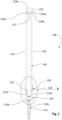
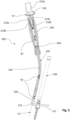
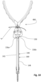
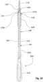
- a rod reducer assembly 100 includes a pedicle screw 110, a pedicle screw housing 120 supported on a proximal or trailing end of the pedicle screw 110, a tab assembly 130 extending proximally from the pedicle screw housing 120, an extension assembly 140 coupled to the tab assembly 130 and extending proximally therefrom, and a head assembly 150 coupled to a proximal end of the extension assembly 140.
- the pedicle screw 110 has a threaded shank 110a and a head 110b supported on the threaded shank 11 0a.
- the head 110b defines a drive recess 11 0c, which may be any suitable shape such as hexolobular or the like.
- the drive recess 110c is configured to selectively receive a drive tool (not shown) such as a screw driver to rotate the threaded shank 110a of the pedicle screw 110 into bone.
- the pedicle screw housing 120 is U-shaped and includes a pair of wings 122a, 122b that defines a U-shaped rod-receiving passage 124 at a proximal end of the pedicle screw housing 120.
- a threaded internal surface 124a is defined by the pair of wings 122a, 122b and is configured to threadably receive a set screw "S" (see FIG. 6 ) therein to engage and secure the spinal rod "R" within the pedicle screw housing 120.
- the pedicle screw housing 120 further defines a concave recess 126 in a distal end thereof that receives the head 110b of the pedicle screw 110.
- An anvil 128 is also received within pedicle screw housing 120 and includes a distal recess 128a that receives the proximal end of the head 110b of the pedicle screw 110 while the head 110b is disposed within the concave recess 126 of the pedicle screw housing 110b.
- the anvil 128 further defines a saddle 128b on a proximal end thereof that supports a spinal rod "R" thereon.
- a spinal rod "R" spinal rod
- the tab assembly 130 includes a pair of tabs 132, 134, each tab of which may be disposed in mirrored relation with the other tab of the pair of tabs 132, 134.
- the tab 132 defines a recess 132a that separates the tab 132 into a pair of arms 132c, 132d at a proximal end of the tab 132.
- the tab 132 further includes a frangible member 132b secured to the wing 122a at a distal end of the tab 132.
- the tab 134 includes a recess 134a that separates tab 134 into a pair of arms (not shown but identical to the pair of arms 132c, 132d) at a proximal end of the tab 132.
- the tab 134 further includes a frangible member 134b secured to a wing 122b at a distal end of the tab 134.
- the frangible members 132b, 134b may be integrally and/or monolithically formed with respective wings 122a, 122b.
- the frangible members 132b, 134b may be configured to break upon application of a threshold force thereto (e.g., twisting, bending, tensile, and/or shear forces) to enable the tabs 132, 134 to separate from the wings 122a, 122b.
- a threshold force e.g., twisting, bending, tensile, and/or shear forces
- break refers to rupturing, dividing, tearing, fracturing, splitting, and/or the like.
- Each of the recesses 132a, 134a receives a ring member or ring 136 therein to couple the extension assembly 140 thereto.
- the extension assembly 140 includes a pair of extensions 142, 144 coupled to the tabs 132, 134 by rings 136.
- Each of the pair of extensions 142, 144 defines a recess 146 in distal end portion thereof and is curved inwardly to define an elongate channel there along (see FIG. 13 ).
- Each recess 146 receives one of the tabs 132, 134 and one of the rings 136 therein.
- a protuberance 148 extends from the recess 146 and is receivable through an opening 136a defined by the ring 136.
- the extension assembly 140 further includes an internal threaded surface 149 in vertical registration with the threaded internal surface 124a of the pedicle screw housing 120.
- the internal threaded surfaces 149 threadably receives the set screw "S” ( FIG. 6 ) and facilitates threaded reception of the set screw "S” into the pedicle screw housing 120 via the threaded internal surface 124a of the pedicle screw housing 120.
- Head assembly 150 defines an inverted U-shape recess 152 that separates a pair of arms 154a, 154b of the head assembly 150. Distal ends of the pair of arms 154a, 154b are coupled to proximal ends of the extensions 142, 144 of the extension assembly 140 by the frangible members 156a, 156b. Similar to the frangible members 132b, 134b of the tab assembly 130, the frangible members 156a, 156b are configured to break upon application of a threshold force thereto to separate the head assembly 150 from the extension assembly 140 as desired.
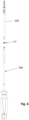
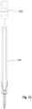
- a rod inserter 200 can be used to insert a spinal rod "R" into the rod reducer assembly 100.
- the rod inserter 200 includes a handle assembly 210 having a proximal handle 210a and a distal handle 210b.
- the proximal and distal handles 210a, 210b are coupled together by a rotation ring 210c and coupling members 210d, 210e.
- An elongate tubular shaft member 220 extends distally from the handle assembly 210 and includes a distal end that has an inner ramp 222.
- the handle assembly 210 and the elongate tubular shaft 210, 220 support an inner shaft 240 and a connector member 250 (e.g., a cable and/or a shaft).
- the inner shaft 240 and the connector member 250 are coupled together via a ball fitting 260 coupled to a proximal end of the connector member 250, for example, via crimping.
- a distal end of connector member 250 is coupled to a working end 230 configured to selectively grasp the spinal rod "R.”
- the rotation ring 210c enables the proximal handle 210a to rotate relative to the distal handle 210b, as indicated by arrows "A.”
- Rotation of the proximal handle 210a causes the inner shaft 240, the connector member 250, and the working end 230 to translate along a centerline "CL" of the rod inserter 200 as indicated by arrows "B.”
- Proximal movement of the working end 230 along the centerline "CL” into the elongated tubular shaft member 220 tightens working end 230 around the spinal rod "R” as the working end 230 engages the inner ramp 222 and loosens the working end 230 around the spinal rod “R” in response to distal movement of the working end 230.
- the working end 230 may be spilt.
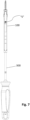
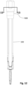
- a split-tip driver 300 can be used to insert the set screw "S" into the rod reducer assembly 100, for example, after the spinal rod “R” ( FIG. 5 ) is positioned within the rod reducer assembly 100 to secure the spinal rod “R” to the rod reducer assembly 100.
- the split-tip driver 300 includes a driver handle assembly 310 having a proximal handle member 310a rotatably mounted to a distal handle member 310b by a threaded coupling feature 312. A proximal end of an inner shaft 314 is threadably coupled to the threaded coupling feature 312.
- An outer tubular shaft 316 extends from a distal end of the handle assembly 310 and slidably receives the inner shaft 314 therein.
- the outer tubular shaft 316 extends to tips 318a, 318b pivotably coupled at a distal end of the outer tubular shaft 316.
- the tips 318a, 318b are split and biased to move radially inwards toward one another.
- the outer tubular shaft 316 and further includes guide nubs 316a, 316b that support the outer tubular shaft 316 within the extension assembly 140 of the rod reducer assembly 100.
- the proximal handle member 310a rotates relative to the distal handle member 310b, as indicated by arrows "C,” to slide the inner shaft 314 longitudinally along a centerline (not shown) of the split-tip driver 300 and through the outer shaft 316, as indicated by arrows "D.”
- the tips 318a, 318b which are receivable within the set screw “S” to hold the set screw “S,” are configured to move between radially inward and radially outward directions, as indicated by arrows "E,” in response to the rotation of the proximal handle member 310a relative to the distal handle member 310b.
- distal movement of the inner shaft 314 relative to the outer shaft 316 moves the tips 318a, 318b radially outwardly, separating the tips 318a, 318b from one another and enabling the tips 318a, 318b to hold the inner surface of the set screw "S" (e.g., via friction fit).
- proximal movement of the inner shaft 314 relative to the outer shaft 316 enables the tips 318a, 318b to move radially inwardly (e.g., the tips 318a, 318b are biased to move toward one another) so that the tips 318a, 318b can separate from the inner surface of the set screw "S.”
- a pair of pliers 400 or the like can be used to separate the head assembly 150 of the rod reducer assembly 100 from the extension assembly 140 of the rod reducer assembly 100, as desired.
- the pliers 400 can be used to break the frangible members 156a, 156b of the head assembly 150 from the extensions 142, 144 of the extension assembly 140 by grasping the head assembly 150 and rotating the head assembly 150 away from the extension assembly 140 as indicated by arrow "F.”
- a clinician can mount a tubular cap member 500 onto the proximal end of the extension assembly 140 as desired to support the extension assembly 140 and maintain a parallel arrangement of the extensions 142, 144 of the extension assembly 140 relative to one another to enable rod reduction while limiting splay.
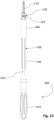
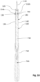
- tab breaker 600 can be utilized to separate the tab and extension assemblies 130, 140 of the rod reducer assembly 100 from the pedicle screw housing 120 of the rod reducer assembly 100 as desired.
- Tab breaker system 600 includes a handle 610, an elongate shaft 620 that extends distally from the handle 610, and a blunt tip 630 supported on a distal end of the elongate shaft 620.
- the tab breaker system 600 further includes a tubular sleeve 640.
- the elongate shaft 620 of the tab breaker system 600 is advanced between the pair of extensions 142, 144 and the tubular sleeve 640 is advanced along an outer surface of the pair of extensions 142, 144.
- the tubular sleeve 640 can be positioned adjacent to the pedicle screw housing 120 and in contact with the tab assembly 130.
- the tab breaker system 600, or components thereof, can then be manipulated (e.g., pivoted, rotated, etc.) as necessary to break the frangible members 132b, 134b of the tab assembly 130, for example, with the pedicle screw 110 secured to bone and a spinal rod (not shown) supported within the U-shaped rod-receiving passage 124 of the pedicle screw housing 120.
- the frangible members 132b, 134b of the tab assembly 130 are broken, the tab assembly 130, the extension assembly 140, and the tab breaker system 600 can be separated from the pedicle screw housing 120.
- tab breaker system 700 includes a handle 710, a coupling portion 720 having a proximal end secured to a distal end of the handle 710, and an elongate shaft 730 extending distally from a distal end of the coupling portion 720 to a blunt tip 740.
- the elongate shaft 730 of the tab breaker system 700 is advanced between the pair of extensions 142, 144 of the extension assembly 140 and the coupling portion 730 is advanced over the proximal end of the extensions 142, 144.
- the tab breaker system 700 With the coupling portion 730 and the elongate shaft 730 of the tab breaker system 700 secured to the extension assembly 140, the tab breaker system 700 can be manipulated as necessary to break the frangible members 132b, 134b of the tab assembly 130 similar to that described above with respect to the tab breaker system 600.
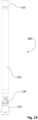
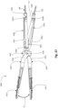
- FIGS. 19-23 illustrate another embodiment of a rod reducer assembly, referred to as rod reducer assembly 800.
- the rod reducer assembly 800 is substantially similar to the rod reducer assembly 100 without the pedicle screw thereof.
- the rod reducer assembly 800 includes a pedicle screw housing 120, a tab assembly 130 extending proximally from the pedicle screw housing 120, an extension assembly 140 coupled to the tab assembly 130 and extending proximally therefrom, and a head assembly 150 coupled to a proximal end of the extension assembly 140.
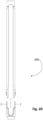
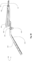
- FIG. 24 is yet another embodiment of a rod reducer assembly, referred to as rod reducer assembly 900.
- the rod reducer assembly 900 is substantially similar to the rod reducer assembly 800.
- rod reducer assembly 900 illustrates that rod reducer assemblies of the present disclosure, or components thereof (e.g., extension and/or tab assemblies), can have any suitable configuration.
- the rod reducer assembly 900 includes a pedicle screw housing 120, a tab assembly 930 extending proximally from the pedicle screw housing 120, an extension assembly 940 coupled to the tab assembly 930 and extending proximally therefrom, and a head assembly 150 coupled to a proximal end of the extension assembly 940.
- the tab assembly 930 includes tabs 932, which may have any suitable shape such as rectangular, that define apertures 934 therethrough configured to receive ring members 136 therein to secure extension assembly 940 to tab assembly 930.
- Extension assembly 940 includes a first extension 942 and a second extension 944.
- Each of the extensions 942, 944 includes an attachment end 946.
- Each attachment end 946 defines a recess 946a on an outer surface thereof and a threaded surface 946b on an inner surface thereof.
- a protuberance 946c extends from each recess 946a.
- Each protuberance 946c is receivable within one of the apertures 934 defined through the tabs 932 and the respective ring member 136 to secure the respective extension 142, 144 to the respective tab 932 similar to that described above with respect to rod reducer assembly 100.
- the ring members 136 can be welded and/or friction fit to the protuberances 946c to secure the extensions 142, 144 to the respective tabs 932.
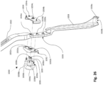
- a modular compressor 1000 can be used to manipulate a first rod reducer assembly 100a and a second rod reducer assembly 100b relative to another.
- the modular compressor 1000 includes a first leg 1010 and a second leg 1020 that are selectively couplable to one another by a fulcrum assembly 1030.
- the first leg 1010 includes a handle 1012 that extends distally to a mounting arm 1014 disposed at an angle relative to the handle 1012.
- the mounting arm 1014 includes a mounting segment 1016 that extends distally from the handle 1012 and a coupling segment 1018 that extends distally from the mounting segment 1016.
- the mounting segment 1016 defines apertures 1016a, 1016b, 1016c therethrough and the coupling segment 1018 extends distally to a foot 1018a.
- the foot 1018a has an enclosed, circumferential shape that defines an opening 1018b configured to receive the head 110b of the pedicle screw 110 of the rod reducer assembly 100.
- the foot 1018a defines a transverse channel 1018c therethrough that is configured to receive a spinal rod, such as spinal rod "R,” therethrough (see Fig. 1 ).
- the second leg 1020 includes a handle 1022 that extends distally to a mounting arm 1024 disposed at an angle relative to the handle 1022.
- the mounting arm 1024 includes a mounting segment 1026 that extends distally from the handle 1022 and a coupling segment 1028 that extends distally from the mounting segment 1026.
- the mounting segment 1026 defines apertures 1026a, 1026b, 1026c therethrough and the coupling segment 1028 extends distally to a foot 1028a.
- the foot 1028a of the second leg 1020 includes an open, arcuate shape and is configured to receive the head 110b of the pedicle screw 110 of the rod reducer assembly 100.
- the foot 1028a defines a transverse channel 1028b configured to receive a spinal rod, such as spinal rod "R,” therethrough (see Fig. 1 ).
- the fulcrum assembly 1030 includes a first plate 1032 and a second plate 1034 that are selectively coupled to one another by a coupling pin 1036 and fasteners 1038a, 1038b.
- the first plate 1032 defines fastener holes 1032a, 1032b and a central pin hole 1032c.
- the second plate 1034 defines fastener holes 1034a, 1034b and a central pin hole 1034c.
- the fastener holes 1032a, 1032b of the first plate 1032 and the fastener holes 1034aa, 1034b of the second plate 1034 are configured to threadably receive the fasteners 1038a, 1038b to couple the first and second plates 1032, 1034 together about one of the mounting segments 1016, 1026 of the respective first and second legs 1010, 1020.
- the coupling pin 1036 includes a base 1036a and a stem 1036b that extends from the base 1036a to a stem head 1036c.
- the coupling pin 1036 further defines a first groove 1036d in an outer surface thereof and proximal to the stem head 1036c, and a second groove 1036e about an outer surface of the stem head 1036c.
- the first and/or second grooves 1036d, 1036e may have an annular configuration.
- the first groove 1036d is configured to longitudinally align with the central pin hole 1034c of the second plate 1034 when the first and second plates 1032, 1034 are coupled to one of the first and second legs 1010, 1020.
- the second groove 1036e is configured to receive a fastening clip 1039 such as a C-clip, a cotter pin, or the like to prevent axial movement of the coupling pin 1036 relative to the first and second legs 101, 1020.
- the central pin holes 1032c, 1034c of the first and second plates 1032, 1034, respectively, are configured to align with one of the apertures 1016a-1016c, 1026a-1026c of the respective first or second legs 1010, 1020 for receiving the coupling pin 1036 therethrough such that the second groove 1036e can be positioned to receive the fastening clip 1039.
- the fastening clip 1039 is configured to prevent axial movement of the coupling pin 1036 to maintain the first and second legs 1010, 1020 pivotally coupled together by the fulcrum assembly 1030.
- the coupling pin 1036 is advanced through the central pin hole 1032c of the first plate 1032, one of the apertures 1016a-1016c, 1026a-1026c of the respective first or second legs 1010, 1020, and the central pin hole 1034c of the second plate 1034c.
- the stem head 1036c projects through the central pin hole 1034c of the second plate 1034c and is positioned to align with one of the apertures 1016a-1016c, 1026a-1026c of the other of the first and second legs 1010, 1020 for receipt therein to pivotally couple the first and second legs 1010, 1020 together as desired.
- the feet 1018a, 1028a of the respective first and second legs 1010, 1020 can be separately attached to one of the first or second rod reducer assemblies 100a, 100b. Once each of the first and second legs 1010, 1020 are coupled to a respective one of the first or second rod reducer assemblies 100a, 100b, the first and second legs 1010, 1020 are pivotally coupled together by positioning the stem head 1036c of the coupling pin 1036 through one of the respective apertures 1016a-1016c, 1026a-1026c of the opposing one of the first and second legs 1010, 1020.
- the fastening clip 1039 can be secured to the stem head 1036c as detailed above to axial fix the position of the coupling pin 1036 and maintain the first and second legs 1010, 1020 pivotally coupled together.
- first and second legs 1010, 1020 are fixedly pivotally coupled together by the coupling pin 1036 and the fastening clip 1039 of the fulcrum assembly 1030, the handles 1012, 1022 of the respective first and second legs 1010, 1020 can be pivoted toward or away from one another, as indicated by arrows "P," to manipulate the first and second rod reducer assemblies 100a, 100b relative to one another while mounted to bone ( Fig. 27 ).
- the feet 1018a, 1028a of the respective first and second legs 1010, 1020 are configured to enable up to at least 10 degrees of angulation of the heads 110b of the pedicle screws 110 of the respective rod reducer assemblies 100a, 100b while pushing along a spinal rod centerline "CL" as the first and second rod reducer assemblies 100a, 100b approximate and/or cross one another in response to compressive pivoting movement of the modular compressor 1000 (see Figs. 27 and 28 ).
- any of the presently disclosed embodiments, or components thereof can be formed of any suitable material or combinations of materials.
- one or more of the presently described rod reducer assemblies 100, 800, and/or 900, and/or one or more components thereof can include mixed metallic materials such as titanium alloy and cobalt-chromium.
- the extension assemblies 140, 940 and the rings 136 can include titanium alloy while the pedicle screw housings 120 and tab assemblies 130, 930 can include cobalt-chromium.
- any of the presently disclosed embodiments, or components thereof can be formed using any suitable technique such as welding, fastening, machining, molding, etc.
- one or more of the components can be secured together using any suitable technique such as welding, fastening, machining, molding, etc.
Landscapes
- Health & Medical Sciences (AREA)
- Orthopedic Medicine & Surgery (AREA)
- Neurology (AREA)
- Life Sciences & Earth Sciences (AREA)
- Surgery (AREA)
- Heart & Thoracic Surgery (AREA)
- Engineering & Computer Science (AREA)
- Biomedical Technology (AREA)
- Nuclear Medicine, Radiotherapy & Molecular Imaging (AREA)
- Medical Informatics (AREA)
- Molecular Biology (AREA)
- Animal Behavior & Ethology (AREA)
- General Health & Medical Sciences (AREA)
- Public Health (AREA)
- Veterinary Medicine (AREA)
- Surgical Instruments (AREA)
Claims (14)
- System zum Befestigen eines Wirbelsäulenstabs (R), das System umfassend:ein Pedikelschraubengehäuse (120) mit Flügeln (122a, 122b), die einen Stabaufnahmedurchgang (124) zwischen den Flügeln (122a, 122b) definieren, wobei der Stabaufnahmedurchgang (124) so gestaltet ist, dass er den Wirbelsäulenstab (R) darin empfängt;eine Lasche (132), die sich von einem der Flügel (122a) aus erstreckt und mit diesem durch ein zerbrechliches Element (132b) verbunden ist; undeine an der Lasche (132) befestigte Verlängerung (142),dadurch gekennzeichnet, dassdie Verlängerung (142) an der Lasche (132) durch einen Vorsprung (148) befestigt ist, der durch eine Öffnung (934) empfangen wird und daran durch ein Ringelement (136) befestigt ist, das auf dem Vorsprung (148) positioniert ist.
- System nach Anspruch 1, wobei die Lasche (132) monolithisch mit dem Pedikelschraubengehäuse (120) ausgebildet ist.
- System nach einem der vorstehenden Ansprüche, wobei das Pedikelschraubengehäuse (120) und die Lasche (132) aus einem ersten Material und die Verlängerung (142) aus einem zweiten Material gebildet sind, wobei das erste und das zweite Material unterschiedlich sind.
- System nach Anspruch 3, wobei das erste Material Kobalt-Chrom einschließt und das zweite Material Titan einschließt.
- System nach einem der vorstehenden Ansprüche, umfassend eine zweite Verlängerung (144), die mit einer zweiten Lasche (134) verbunden ist, wobei die zweite Lasche (134) von einem der Flügel (122b) ausgeht.
- System nach Anspruch 5, wobei die zweite Lasche (134) ein zerbrechliches Element (134b) einschließt, das mit einem der Flügel (122b) verbunden ist.
- System nach einem der vorstehenden Ansprüche, wobei die Verlängerung (142) und das Ringelement (136) das gleiche Material einschließen.
- System nach Anspruch 7, wobei die Verlängerung (142) und das Ringelement (136) Titan oder eine Titanlegierung einschließen.
- System nach einem der vorstehenden Ansprüche, das ferner einen Pedikelschraubenschaft (110) einschließt, der mit dem Pedikelschraubengehäuse (120) verbunden ist.
- System nach einem der vorstehenden Ansprüche, wobei die Verlängerung (140) eine erste Verlängerung (142) und eine zweite Verlängerung (144) einschließt und die Lasche (130) eine erste Lasche (132) und eine zweite Lasche (134) einschließt, wobei die erste Verlängerung (142) mit der ersten Lasche (132) und die zweite Verlängerung (144) mit der zweiten Lasche (134) verbunden ist.
- System nach einem der vorstehenden Ansprüche, wobei die Verlängerung (140) eine erste Verlängerung (142) und eine zweite Verlängerung (144) einschließt und das zerbrechliche Element ein erstes zerbrechliches Element (132b) und ein zweites zerbrechliches Element (134b) einschließt, wobei das erste zerbrechliche Element (132b) zwischen der ersten Verlängerung (142) und dem Pedikelschraubengehäuse (120) gekoppelt ist und das zweite zerbrechliche Element (134b) zwischen der zweiten Verlängerung (144) und dem Pedikelschraubengehäuse (120) gekoppelt ist.
- System nach einem der vorstehenden Ansprüche, wobei das Pedikelschraubengehäuse (120), die Lasche (132) und die Verlängerung (142) zusammen eine Stabreduziervorrichtung (100) bilden.
- System nach einem der vorstehenden Ansprüche, wobei das zerbrechliche Element (132b) so konfiguriert ist, dass es bei Anwendung einer Schwellenkraft darauf bricht.
- System, umfassend:
mindestens ein System nach Anspruch 12; und einen modularen Kompressor (1000), der ein erstes Bein (1010) und ein zweites Bein (1020) einschließt, die durch eine Drehpunktanordnung (1030) schwenkbar gekoppelt sind, um die mindestens eine Stabreduzieranordnung (100) selektiv zu manipulieren.
Applications Claiming Priority (2)
| Application Number | Priority Date | Filing Date | Title |
|---|---|---|---|
| US201562204553P | 2015-08-13 | 2015-08-13 | |
| PCT/US2016/046523 WO2017027694A1 (en) | 2015-08-13 | 2016-08-11 | Extended tab systems for reducing spinal rods |
Publications (3)
| Publication Number | Publication Date |
|---|---|
| EP3334355A1 EP3334355A1 (de) | 2018-06-20 |
| EP3334355A4 EP3334355A4 (de) | 2019-07-31 |
| EP3334355B1 true EP3334355B1 (de) | 2024-04-10 |
Family
ID=57984094
Family Applications (1)
| Application Number | Title | Priority Date | Filing Date |
|---|---|---|---|
| EP16835901.6A Active EP3334355B1 (de) | 2015-08-13 | 2016-08-11 | Verlängerte laschensysteme zur reduzierung von wirbelsäulenstangen |
Country Status (4)
| Country | Link |
|---|---|
| US (2) | US10702317B2 (de) |
| EP (1) | EP3334355B1 (de) |
| AU (1) | AU2016304924B2 (de) |
| WO (1) | WO2017027694A1 (de) |
Families Citing this family (15)
| Publication number | Priority date | Publication date | Assignee | Title |
|---|---|---|---|---|
| US20190336182A1 (en) * | 2015-10-27 | 2019-11-07 | Ctl Medical Corporation | Modular rod reduction tower and related methods |
| US10779866B2 (en) | 2016-12-29 | 2020-09-22 | K2M, Inc. | Rod reducer assembly |
| US10973558B2 (en) | 2017-06-12 | 2021-04-13 | K2M, Inc. | Screw insertion instrument and methods of use |
| WO2019217045A1 (en) | 2018-05-09 | 2019-11-14 | Zimmer Biomet Spine, Inc. | Anchoring device with extended tabs |
| US11484350B2 (en) | 2018-12-13 | 2022-11-01 | Zimmer Biomet Spine, Inc. | Split tower for a bone anchor |
| IT201900005358A1 (it) * | 2019-04-08 | 2020-10-08 | Medacta Int Sa | Vite chirurgica poliassiale e dispositivo per l’impianto di detta vite chirurgica |
| CN114828762B (zh) * | 2019-12-11 | 2024-11-29 | 尼奥医疗公司 | 具有减小的直径的u形弯曲结构的骨科螺钉延长器 |
| KR102343236B1 (ko) * | 2020-01-14 | 2021-12-23 | 박상호 | 척추 고정 모듈 |
| US11690655B2 (en) | 2020-01-17 | 2023-07-04 | Warsaw Orthopedic, Inc. | Monolithic percutaneous-screw system for spinal surgeries |
| US11134994B2 (en) * | 2020-01-30 | 2021-10-05 | Warsaw Orthopedic, Inc. | Spinal-correction system having threaded extender tabs and reduction tab extenders |
| US11191574B2 (en) * | 2020-03-17 | 2021-12-07 | Warsaw Orthopedic, Inc. | Set screw reducer for modular reduction screws |
| CN111671529A (zh) * | 2020-06-16 | 2020-09-18 | 山东省立医院 | 一种智能精确的口腔临床用定位器 |
| US12029454B2 (en) * | 2020-07-22 | 2024-07-09 | Zimmer Biomet Spine, Inc. | Extended tab separation apparatus and method |
| US12262927B2 (en) | 2020-12-10 | 2025-04-01 | K2M, Inc. | Screw insertion instrument and methods of use |
| US20250261973A1 (en) * | 2024-02-20 | 2025-08-21 | Ulrich Medical, USA | Pedicle screw assembly |
Family Cites Families (51)
| Publication number | Priority date | Publication date | Assignee | Title |
|---|---|---|---|---|
| US6740089B2 (en) | 2002-01-10 | 2004-05-25 | Thomas T. Haider | Orthopedic hook system |
| US7842073B2 (en) | 2002-04-18 | 2010-11-30 | Aesculap Ii, Inc. | Screw and rod fixation assembly and device |
| US6740086B2 (en) | 2002-04-18 | 2004-05-25 | Spinal Innovations, Llc | Screw and rod fixation assembly and device |
| US8876868B2 (en) | 2002-09-06 | 2014-11-04 | Roger P. Jackson | Helical guide and advancement flange with radially loaded lip |
| DE102004027881B4 (de) | 2004-05-28 | 2006-06-01 | Aesculap Ag & Co. Kg | Knochenschraube und Osteosynthesevorrichtung |
| US7186255B2 (en) | 2004-08-12 | 2007-03-06 | Atlas Spine, Inc. | Polyaxial screw |
| EP1811911A4 (de) | 2004-11-10 | 2012-01-11 | Roger P Jackson | Spiralförmige führung und vorschiebeflansch mit abbruchverlängerungen |
| US7811288B2 (en) * | 2004-12-02 | 2010-10-12 | Zimmer Spine, Inc. | Instruments and methods for adjusting separation distance of vertebral bodies with a minimally invasive spinal stabilization procedure |
| US7846093B2 (en) | 2005-09-26 | 2010-12-07 | K2M, Inc. | Minimally invasive retractor and methods of use |
| US8075599B2 (en) | 2005-10-18 | 2011-12-13 | Warsaw Orthopedic, Inc. | Adjustable bone anchor assembly |
| US7927360B2 (en) | 2006-01-26 | 2011-04-19 | Warsaw Orthopedic, Inc. | Spinal anchor assemblies having extended receivers |
| US8894655B2 (en) | 2006-02-06 | 2014-11-25 | Stryker Spine | Rod contouring apparatus and method for percutaneous pedicle screw extension |
| US8821506B2 (en) | 2006-05-11 | 2014-09-02 | Michael David Mitchell | Bone screw |
| US20080015601A1 (en) | 2006-06-14 | 2008-01-17 | Michael Castro | Reduction device and method of use |
| US8663292B2 (en) | 2006-08-22 | 2014-03-04 | DePuy Synthes Products, LLC | Reduction sleeve |
| US8262662B2 (en) | 2006-11-20 | 2012-09-11 | Depuy Spine, Inc. | Break-off screw extensions |
| US8221471B2 (en) | 2007-05-24 | 2012-07-17 | Aesculap Implant Systems, Llc | Pedicle screw fixation system |
| US8491590B2 (en) * | 2007-12-05 | 2013-07-23 | Depuy Spine, Inc. | System and method of manipulating spinal constructs |
| US8998958B2 (en) | 2007-12-20 | 2015-04-07 | Aesculap Implant Systems, Llc | Locking device introducer instrument |
| US9579126B2 (en) | 2008-02-02 | 2017-02-28 | Globus Medical, Inc. | Spinal rod link reducer |
| US9050141B2 (en) | 2008-02-02 | 2015-06-09 | Texas Scottish Rite Hospital For Children | Pedicle screw |
| US9345517B2 (en) | 2008-02-02 | 2016-05-24 | Globus Medical, Inc. | Pedicle screw having a removable rod coupling |
| US8246538B2 (en) | 2008-02-28 | 2012-08-21 | K2M, Inc. | Minimally invasive retractor with separable blades and methods of use |
| US8932210B2 (en) | 2008-02-28 | 2015-01-13 | K2M, Inc. | Minimally invasive retraction device having detachable blades |
| US8709015B2 (en) | 2008-03-10 | 2014-04-29 | DePuy Synthes Products, LLC | Bilateral vertebral body derotation system |
| US8764754B2 (en) | 2008-03-21 | 2014-07-01 | Life Spine, Inc. | Systems and methods for spinal rod insertion and reduction |
| KR20110008033A (ko) | 2008-04-22 | 2011-01-25 | 신세스 게엠바하 | 정복 탭을 갖는 뼈 고정 요소 |
| US8444649B2 (en) * | 2008-07-07 | 2013-05-21 | Depuy Spine, Inc. | System and method for manipulating a spinal construct |
| US8388659B1 (en) | 2008-10-17 | 2013-03-05 | Theken Spine, Llc | Spondylolisthesis screw and instrument for implantation |
| EP2737866B1 (de) * | 2008-10-23 | 2021-05-19 | Alphatec Spine, Inc. | Systeme zur Wirbelsäulenfixierung |
| US9750545B2 (en) | 2009-03-27 | 2017-09-05 | Globus Medical, Inc. | Devices and methods for inserting a vertebral fixation member |
| US8236032B2 (en) | 2009-10-20 | 2012-08-07 | Depuy Spine, Inc. | Spinal implant with a flexible extension element |
| US20110257690A1 (en) * | 2010-04-20 | 2011-10-20 | Warsaw Orthopedic, Inc. | Transverse and Sagittal Adjusting Screw |
| WO2012024665A2 (en) | 2010-08-20 | 2012-02-23 | K2M, Inc. | Spinal fixation system |
| US9393049B2 (en) | 2010-08-20 | 2016-07-19 | K2M, Inc. | Spinal fixation system |
| US8685029B2 (en) | 2010-09-27 | 2014-04-01 | DePuy Synthes Products, LLC | Rod reduction instrument and methods of rod reduction |
| US20120109208A1 (en) | 2010-10-27 | 2012-05-03 | Warsaw Orthopedic, Inc. | Low Profile Extension Attachments for Bone Anchors |
| US9289250B2 (en) * | 2011-10-17 | 2016-03-22 | Warsaw Orthopedic, Inc. | Extender collar system |
| US8956361B2 (en) | 2011-12-19 | 2015-02-17 | Amendia, Inc. | Extended tab bone screw system |
| FR2988582B1 (fr) | 2012-04-02 | 2014-03-14 | Safe Orthopaedics | Kit d'instrumentation |
| US9393054B2 (en) | 2012-06-26 | 2016-07-19 | K2M, Inc. | Spinal rod locking holder |
| US20140214084A1 (en) | 2013-01-28 | 2014-07-31 | Roger P. Jackson | Polyaxial bone anchor with receiver with spheric edge for friction fit |
| US8852239B2 (en) | 2013-02-15 | 2014-10-07 | Roger P Jackson | Sagittal angle screw with integral shank and receiver |
| US8951258B2 (en) * | 2013-03-01 | 2015-02-10 | Warsaw Orthopedic, Inc. | Spinal correction system and method |
| CA2846149C (en) | 2013-03-14 | 2018-03-20 | Stryker Spine | Systems and methods for percutaneous spinal fusion |
| US9125694B2 (en) | 2013-05-06 | 2015-09-08 | Life Spine, Inc. | Systems and methods for spinal rod insertion and reduction |
| JP6290002B2 (ja) | 2013-06-07 | 2018-03-07 | 賢 石井 | 脊椎固定用装置 |
| US9265533B2 (en) | 2013-09-04 | 2016-02-23 | Aesculap Implant Systems, Llc | Rod persuader, system and method |
| DE102013110796A1 (de) | 2013-09-30 | 2015-04-02 | Z-Medical Gmbh & Co. Kg | Chirurgisches Instrument |
| US20160345952A1 (en) | 2014-01-29 | 2016-12-01 | Spinal Usa, Inc. | Minimally invasive devices, systems and methods for treating the spine |
| US8858605B1 (en) | 2014-03-06 | 2014-10-14 | Amendia, Inc. | Tab bone screw system |
-
2016
- 2016-08-11 AU AU2016304924A patent/AU2016304924B2/en active Active
- 2016-08-11 WO PCT/US2016/046523 patent/WO2017027694A1/en not_active Ceased
- 2016-08-11 EP EP16835901.6A patent/EP3334355B1/de active Active
- 2016-08-11 US US15/752,142 patent/US10702317B2/en active Active
-
2020
- 2020-06-23 US US16/909,266 patent/US11839415B2/en active Active
Also Published As
| Publication number | Publication date |
|---|---|
| US11839415B2 (en) | 2023-12-12 |
| EP3334355A4 (de) | 2019-07-31 |
| AU2016304924A1 (en) | 2018-03-01 |
| US10702317B2 (en) | 2020-07-07 |
| WO2017027694A1 (en) | 2017-02-16 |
| AU2016304924B2 (en) | 2021-04-29 |
| US20180235677A1 (en) | 2018-08-23 |
| US20200390480A1 (en) | 2020-12-17 |
| EP3334355A1 (de) | 2018-06-20 |
Similar Documents
| Publication | Publication Date | Title |
|---|---|---|
| EP3334355B1 (de) | Verlängerte laschensysteme zur reduzierung von wirbelsäulenstangen | |
| US8992579B1 (en) | Lateral fixation constructs and related methods | |
| EP3351184B1 (de) | Vorrichtungen und systeme für chirurgische retraktion | |
| US8882817B2 (en) | Spinal fixation system | |
| AU2011227073B2 (en) | Spinal fixation apparatus and methods | |
| US9517099B2 (en) | System for corrective spinal surgery and method of use | |
| US8685065B1 (en) | Tools for implantation of interspinous implants and methods thereof | |
| US10813670B2 (en) | Spinal stabilization system | |
| US10973552B2 (en) | Surgical system for bone screw insertion and rod reduction | |
| US20130150864A1 (en) | Surgical instrument and method | |
| US9393054B2 (en) | Spinal rod locking holder | |
| US10575876B2 (en) | Spinal stabilization assemblies with bone hooks | |
| US20170143385A1 (en) | Spinal rod reduction system | |
| US10806494B2 (en) | Fixation devices, fixation systems, and methods of using the same | |
| AU2016203448B2 (en) | Surgical system for bone screw insertion and rod reduction | |
| AU2014200455B2 (en) | Spinal Fixation System |
Legal Events
| Date | Code | Title | Description |
|---|---|---|---|
| STAA | Information on the status of an ep patent application or granted ep patent |
Free format text: STATUS: THE INTERNATIONAL PUBLICATION HAS BEEN MADE |
|
| PUAI | Public reference made under article 153(3) epc to a published international application that has entered the european phase |
Free format text: ORIGINAL CODE: 0009012 |
|
| STAA | Information on the status of an ep patent application or granted ep patent |
Free format text: STATUS: REQUEST FOR EXAMINATION WAS MADE |
|
| 17P | Request for examination filed |
Effective date: 20180305 |
|
| AK | Designated contracting states |
Kind code of ref document: A1 Designated state(s): AL AT BE BG CH CY CZ DE DK EE ES FI FR GB GR HR HU IE IS IT LI LT LU LV MC MK MT NL NO PL PT RO RS SE SI SK SM TR |
|
| AX | Request for extension of the european patent |
Extension state: BA ME |
|
| DAV | Request for validation of the european patent (deleted) | ||
| DAX | Request for extension of the european patent (deleted) | ||
| RIC1 | Information provided on ipc code assigned before grant |
Ipc: A61B 17/58 20060101AFI20190325BHEP Ipc: A61B 17/76 20060101ALI20190325BHEP Ipc: A61B 17/70 20060101ALI20190325BHEP Ipc: A61B 17/86 20060101ALI20190325BHEP Ipc: A61B 17/68 20060101ALI20190325BHEP |
|
| A4 | Supplementary search report drawn up and despatched |
Effective date: 20190701 |
|
| RIC1 | Information provided on ipc code assigned before grant |
Ipc: A61B 17/70 20060101ALI20190625BHEP Ipc: A61B 17/68 20060101ALI20190625BHEP Ipc: A61B 17/76 20060101ALI20190625BHEP Ipc: A61B 17/86 20060101ALI20190625BHEP Ipc: A61B 17/58 20060101AFI20190625BHEP |
|
| RIN1 | Information on inventor provided before grant (corrected) |
Inventor name: GENOVESE, DANIEL Inventor name: RICHOLT, JENS Inventor name: RUBIN, JOSH Inventor name: KAM, ANDREW Inventor name: DANDIE, GORDON DUNCAN CHARLES Inventor name: GOLDWOOD, GENEVA |
|
| STAA | Information on the status of an ep patent application or granted ep patent |
Free format text: STATUS: EXAMINATION IS IN PROGRESS |
|
| 17Q | First examination report despatched |
Effective date: 20221114 |
|
| GRAP | Despatch of communication of intention to grant a patent |
Free format text: ORIGINAL CODE: EPIDOSNIGR1 |
|
| STAA | Information on the status of an ep patent application or granted ep patent |
Free format text: STATUS: GRANT OF PATENT IS INTENDED |
|
| INTG | Intention to grant announced |
Effective date: 20231120 |
|
| GRAS | Grant fee paid |
Free format text: ORIGINAL CODE: EPIDOSNIGR3 |
|
| GRAA | (expected) grant |
Free format text: ORIGINAL CODE: 0009210 |
|
| STAA | Information on the status of an ep patent application or granted ep patent |
Free format text: STATUS: THE PATENT HAS BEEN GRANTED |
|
| AK | Designated contracting states |
Kind code of ref document: B1 Designated state(s): AL AT BE BG CH CY CZ DE DK EE ES FI FR GB GR HR HU IE IS IT LI LT LU LV MC MK MT NL NO PL PT RO RS SE SI SK SM TR |
|
| REG | Reference to a national code |
Ref country code: GB Ref legal event code: FG4D |
|
| REG | Reference to a national code |
Ref country code: CH Ref legal event code: EP |
|
| P01 | Opt-out of the competence of the unified patent court (upc) registered |
Effective date: 20240308 |
|
| REG | Reference to a national code |
Ref country code: DE Ref legal event code: R096 Ref document number: 602016086876 Country of ref document: DE |
|
| REG | Reference to a national code |
Ref country code: IE Ref legal event code: FG4D |
|
| REG | Reference to a national code |
Ref country code: LT Ref legal event code: MG9D |
|
| REG | Reference to a national code |
Ref country code: NL Ref legal event code: MP Effective date: 20240410 |
|
| REG | Reference to a national code |
Ref country code: AT Ref legal event code: MK05 Ref document number: 1674083 Country of ref document: AT Kind code of ref document: T Effective date: 20240410 |
|
| PG25 | Lapsed in a contracting state [announced via postgrant information from national office to epo] |
Ref country code: NL Free format text: LAPSE BECAUSE OF FAILURE TO SUBMIT A TRANSLATION OF THE DESCRIPTION OR TO PAY THE FEE WITHIN THE PRESCRIBED TIME-LIMIT Effective date: 20240410 |
|
| PG25 | Lapsed in a contracting state [announced via postgrant information from national office to epo] |
Ref country code: NL Free format text: LAPSE BECAUSE OF FAILURE TO SUBMIT A TRANSLATION OF THE DESCRIPTION OR TO PAY THE FEE WITHIN THE PRESCRIBED TIME-LIMIT Effective date: 20240410 |
|
| PG25 | Lapsed in a contracting state [announced via postgrant information from national office to epo] |
Ref country code: IS Free format text: LAPSE BECAUSE OF FAILURE TO SUBMIT A TRANSLATION OF THE DESCRIPTION OR TO PAY THE FEE WITHIN THE PRESCRIBED TIME-LIMIT Effective date: 20240810 |
|
| PG25 | Lapsed in a contracting state [announced via postgrant information from national office to epo] |
Ref country code: BG Free format text: LAPSE BECAUSE OF FAILURE TO SUBMIT A TRANSLATION OF THE DESCRIPTION OR TO PAY THE FEE WITHIN THE PRESCRIBED TIME-LIMIT Effective date: 20240410 |
|
| PG25 | Lapsed in a contracting state [announced via postgrant information from national office to epo] |
Ref country code: FI Free format text: LAPSE BECAUSE OF FAILURE TO SUBMIT A TRANSLATION OF THE DESCRIPTION OR TO PAY THE FEE WITHIN THE PRESCRIBED TIME-LIMIT Effective date: 20240410 Ref country code: HR Free format text: LAPSE BECAUSE OF FAILURE TO SUBMIT A TRANSLATION OF THE DESCRIPTION OR TO PAY THE FEE WITHIN THE PRESCRIBED TIME-LIMIT Effective date: 20240410 |
|
| PG25 | Lapsed in a contracting state [announced via postgrant information from national office to epo] |
Ref country code: GR Free format text: LAPSE BECAUSE OF FAILURE TO SUBMIT A TRANSLATION OF THE DESCRIPTION OR TO PAY THE FEE WITHIN THE PRESCRIBED TIME-LIMIT Effective date: 20240711 |
|
| PG25 | Lapsed in a contracting state [announced via postgrant information from national office to epo] |
Ref country code: PT Free format text: LAPSE BECAUSE OF FAILURE TO SUBMIT A TRANSLATION OF THE DESCRIPTION OR TO PAY THE FEE WITHIN THE PRESCRIBED TIME-LIMIT Effective date: 20240812 |
|
| PG25 | Lapsed in a contracting state [announced via postgrant information from national office to epo] |
Ref country code: ES Free format text: LAPSE BECAUSE OF FAILURE TO SUBMIT A TRANSLATION OF THE DESCRIPTION OR TO PAY THE FEE WITHIN THE PRESCRIBED TIME-LIMIT Effective date: 20240410 |
|
| PG25 | Lapsed in a contracting state [announced via postgrant information from national office to epo] |
Ref country code: AT Free format text: LAPSE BECAUSE OF FAILURE TO SUBMIT A TRANSLATION OF THE DESCRIPTION OR TO PAY THE FEE WITHIN THE PRESCRIBED TIME-LIMIT Effective date: 20240410 |
|
| PG25 | Lapsed in a contracting state [announced via postgrant information from national office to epo] |
Ref country code: PL Free format text: LAPSE BECAUSE OF FAILURE TO SUBMIT A TRANSLATION OF THE DESCRIPTION OR TO PAY THE FEE WITHIN THE PRESCRIBED TIME-LIMIT Effective date: 20240410 |
|
| PG25 | Lapsed in a contracting state [announced via postgrant information from national office to epo] |
Ref country code: LV Free format text: LAPSE BECAUSE OF FAILURE TO SUBMIT A TRANSLATION OF THE DESCRIPTION OR TO PAY THE FEE WITHIN THE PRESCRIBED TIME-LIMIT Effective date: 20240410 |
|
| PG25 | Lapsed in a contracting state [announced via postgrant information from national office to epo] |
Ref country code: PT Free format text: LAPSE BECAUSE OF FAILURE TO SUBMIT A TRANSLATION OF THE DESCRIPTION OR TO PAY THE FEE WITHIN THE PRESCRIBED TIME-LIMIT Effective date: 20240812 Ref country code: PL Free format text: LAPSE BECAUSE OF FAILURE TO SUBMIT A TRANSLATION OF THE DESCRIPTION OR TO PAY THE FEE WITHIN THE PRESCRIBED TIME-LIMIT Effective date: 20240410 Ref country code: NO Free format text: LAPSE BECAUSE OF FAILURE TO SUBMIT A TRANSLATION OF THE DESCRIPTION OR TO PAY THE FEE WITHIN THE PRESCRIBED TIME-LIMIT Effective date: 20240710 Ref country code: LV Free format text: LAPSE BECAUSE OF FAILURE TO SUBMIT A TRANSLATION OF THE DESCRIPTION OR TO PAY THE FEE WITHIN THE PRESCRIBED TIME-LIMIT Effective date: 20240410 Ref country code: IS Free format text: LAPSE BECAUSE OF FAILURE TO SUBMIT A TRANSLATION OF THE DESCRIPTION OR TO PAY THE FEE WITHIN THE PRESCRIBED TIME-LIMIT Effective date: 20240810 Ref country code: HR Free format text: LAPSE BECAUSE OF FAILURE TO SUBMIT A TRANSLATION OF THE DESCRIPTION OR TO PAY THE FEE WITHIN THE PRESCRIBED TIME-LIMIT Effective date: 20240410 Ref country code: GR Free format text: LAPSE BECAUSE OF FAILURE TO SUBMIT A TRANSLATION OF THE DESCRIPTION OR TO PAY THE FEE WITHIN THE PRESCRIBED TIME-LIMIT Effective date: 20240711 Ref country code: FI Free format text: LAPSE BECAUSE OF FAILURE TO SUBMIT A TRANSLATION OF THE DESCRIPTION OR TO PAY THE FEE WITHIN THE PRESCRIBED TIME-LIMIT Effective date: 20240410 Ref country code: ES Free format text: LAPSE BECAUSE OF FAILURE TO SUBMIT A TRANSLATION OF THE DESCRIPTION OR TO PAY THE FEE WITHIN THE PRESCRIBED TIME-LIMIT Effective date: 20240410 Ref country code: BG Free format text: LAPSE BECAUSE OF FAILURE TO SUBMIT A TRANSLATION OF THE DESCRIPTION OR TO PAY THE FEE WITHIN THE PRESCRIBED TIME-LIMIT Effective date: 20240410 Ref country code: AT Free format text: LAPSE BECAUSE OF FAILURE TO SUBMIT A TRANSLATION OF THE DESCRIPTION OR TO PAY THE FEE WITHIN THE PRESCRIBED TIME-LIMIT Effective date: 20240410 Ref country code: RS Free format text: LAPSE BECAUSE OF FAILURE TO SUBMIT A TRANSLATION OF THE DESCRIPTION OR TO PAY THE FEE WITHIN THE PRESCRIBED TIME-LIMIT Effective date: 20240710 |
|
| REG | Reference to a national code |
Ref country code: DE Ref legal event code: R097 Ref document number: 602016086876 Country of ref document: DE |
|
| PG25 | Lapsed in a contracting state [announced via postgrant information from national office to epo] |
Ref country code: DK Free format text: LAPSE BECAUSE OF FAILURE TO SUBMIT A TRANSLATION OF THE DESCRIPTION OR TO PAY THE FEE WITHIN THE PRESCRIBED TIME-LIMIT Effective date: 20240410 |
|
| PG25 | Lapsed in a contracting state [announced via postgrant information from national office to epo] |
Ref country code: EE Free format text: LAPSE BECAUSE OF FAILURE TO SUBMIT A TRANSLATION OF THE DESCRIPTION OR TO PAY THE FEE WITHIN THE PRESCRIBED TIME-LIMIT Effective date: 20240410 |
|
| PG25 | Lapsed in a contracting state [announced via postgrant information from national office to epo] |
Ref country code: CZ Free format text: LAPSE BECAUSE OF FAILURE TO SUBMIT A TRANSLATION OF THE DESCRIPTION OR TO PAY THE FEE WITHIN THE PRESCRIBED TIME-LIMIT Effective date: 20240410 |
|
| PG25 | Lapsed in a contracting state [announced via postgrant information from national office to epo] |
Ref country code: RO Free format text: LAPSE BECAUSE OF FAILURE TO SUBMIT A TRANSLATION OF THE DESCRIPTION OR TO PAY THE FEE WITHIN THE PRESCRIBED TIME-LIMIT Effective date: 20240410 Ref country code: SK Free format text: LAPSE BECAUSE OF FAILURE TO SUBMIT A TRANSLATION OF THE DESCRIPTION OR TO PAY THE FEE WITHIN THE PRESCRIBED TIME-LIMIT Effective date: 20240410 |
|
| PG25 | Lapsed in a contracting state [announced via postgrant information from national office to epo] |
Ref country code: SM Free format text: LAPSE BECAUSE OF FAILURE TO SUBMIT A TRANSLATION OF THE DESCRIPTION OR TO PAY THE FEE WITHIN THE PRESCRIBED TIME-LIMIT Effective date: 20240410 |
|
| PG25 | Lapsed in a contracting state [announced via postgrant information from national office to epo] |
Ref country code: SM Free format text: LAPSE BECAUSE OF FAILURE TO SUBMIT A TRANSLATION OF THE DESCRIPTION OR TO PAY THE FEE WITHIN THE PRESCRIBED TIME-LIMIT Effective date: 20240410 Ref country code: SK Free format text: LAPSE BECAUSE OF FAILURE TO SUBMIT A TRANSLATION OF THE DESCRIPTION OR TO PAY THE FEE WITHIN THE PRESCRIBED TIME-LIMIT Effective date: 20240410 Ref country code: RO Free format text: LAPSE BECAUSE OF FAILURE TO SUBMIT A TRANSLATION OF THE DESCRIPTION OR TO PAY THE FEE WITHIN THE PRESCRIBED TIME-LIMIT Effective date: 20240410 Ref country code: EE Free format text: LAPSE BECAUSE OF FAILURE TO SUBMIT A TRANSLATION OF THE DESCRIPTION OR TO PAY THE FEE WITHIN THE PRESCRIBED TIME-LIMIT Effective date: 20240410 Ref country code: DK Free format text: LAPSE BECAUSE OF FAILURE TO SUBMIT A TRANSLATION OF THE DESCRIPTION OR TO PAY THE FEE WITHIN THE PRESCRIBED TIME-LIMIT Effective date: 20240410 Ref country code: CZ Free format text: LAPSE BECAUSE OF FAILURE TO SUBMIT A TRANSLATION OF THE DESCRIPTION OR TO PAY THE FEE WITHIN THE PRESCRIBED TIME-LIMIT Effective date: 20240410 |
|
| PG25 | Lapsed in a contracting state [announced via postgrant information from national office to epo] |
Ref country code: IT Free format text: LAPSE BECAUSE OF FAILURE TO SUBMIT A TRANSLATION OF THE DESCRIPTION OR TO PAY THE FEE WITHIN THE PRESCRIBED TIME-LIMIT Effective date: 20240410 |
|
| PLBE | No opposition filed within time limit |
Free format text: ORIGINAL CODE: 0009261 |
|
| STAA | Information on the status of an ep patent application or granted ep patent |
Free format text: STATUS: NO OPPOSITION FILED WITHIN TIME LIMIT |
|
| 26N | No opposition filed |
Effective date: 20250113 |
|
| REG | Reference to a national code |
Ref country code: CH Ref legal event code: PL |
|
| PG25 | Lapsed in a contracting state [announced via postgrant information from national office to epo] |
Ref country code: LU Free format text: LAPSE BECAUSE OF NON-PAYMENT OF DUE FEES Effective date: 20240811 |
|
| PG25 | Lapsed in a contracting state [announced via postgrant information from national office to epo] |
Ref country code: MC Free format text: LAPSE BECAUSE OF FAILURE TO SUBMIT A TRANSLATION OF THE DESCRIPTION OR TO PAY THE FEE WITHIN THE PRESCRIBED TIME-LIMIT Effective date: 20240410 Ref country code: SI Free format text: LAPSE BECAUSE OF FAILURE TO SUBMIT A TRANSLATION OF THE DESCRIPTION OR TO PAY THE FEE WITHIN THE PRESCRIBED TIME-LIMIT Effective date: 20240410 Ref country code: CH Free format text: LAPSE BECAUSE OF NON-PAYMENT OF DUE FEES Effective date: 20240831 |
|
| REG | Reference to a national code |
Ref country code: BE Ref legal event code: MM Effective date: 20240831 |
|
| PGFP | Annual fee paid to national office [announced via postgrant information from national office to epo] |
Ref country code: GB Payment date: 20250619 Year of fee payment: 10 |
|
| PG25 | Lapsed in a contracting state [announced via postgrant information from national office to epo] |
Ref country code: BE Free format text: LAPSE BECAUSE OF NON-PAYMENT OF DUE FEES Effective date: 20240831 |
|
| PGFP | Annual fee paid to national office [announced via postgrant information from national office to epo] |
Ref country code: FR Payment date: 20250623 Year of fee payment: 10 |
|
| PG25 | Lapsed in a contracting state [announced via postgrant information from national office to epo] |
Ref country code: IE Free format text: LAPSE BECAUSE OF NON-PAYMENT OF DUE FEES Effective date: 20240811 |
|
| PG25 | Lapsed in a contracting state [announced via postgrant information from national office to epo] |
Ref country code: SE Free format text: LAPSE BECAUSE OF FAILURE TO SUBMIT A TRANSLATION OF THE DESCRIPTION OR TO PAY THE FEE WITHIN THE PRESCRIBED TIME-LIMIT Effective date: 20240410 |
|
| PGFP | Annual fee paid to national office [announced via postgrant information from national office to epo] |
Ref country code: DE Payment date: 20250618 Year of fee payment: 10 |
|
| PG25 | Lapsed in a contracting state [announced via postgrant information from national office to epo] |
Ref country code: CY Free format text: LAPSE BECAUSE OF FAILURE TO SUBMIT A TRANSLATION OF THE DESCRIPTION OR TO PAY THE FEE WITHIN THE PRESCRIBED TIME-LIMIT; INVALID AB INITIO Effective date: 20160811 |
|
| PG25 | Lapsed in a contracting state [announced via postgrant information from national office to epo] |
Ref country code: HU Free format text: LAPSE BECAUSE OF FAILURE TO SUBMIT A TRANSLATION OF THE DESCRIPTION OR TO PAY THE FEE WITHIN THE PRESCRIBED TIME-LIMIT; INVALID AB INITIO Effective date: 20160811 |