EP3334270B1 - Electric lawn mower with electromagnetic parking break - Google Patents
Electric lawn mower with electromagnetic parking break Download PDFInfo
- Publication number
- EP3334270B1 EP3334270B1 EP16745781.1A EP16745781A EP3334270B1 EP 3334270 B1 EP3334270 B1 EP 3334270B1 EP 16745781 A EP16745781 A EP 16745781A EP 3334270 B1 EP3334270 B1 EP 3334270B1
- Authority
- EP
- European Patent Office
- Prior art keywords
- motor
- electric
- mower
- switch
- terminals
- Prior art date
- Legal status (The legal status is an assumption and is not a legal conclusion. Google has not performed a legal analysis and makes no representation as to the accuracy of the status listed.)
- Active
Links
Images


Classifications
-
- A—HUMAN NECESSITIES
- A01—AGRICULTURE; FORESTRY; ANIMAL HUSBANDRY; HUNTING; TRAPPING; FISHING
- A01D—HARVESTING; MOWING
- A01D69/00—Driving mechanisms or parts thereof for harvesters or mowers
- A01D69/10—Brakes
Landscapes
- Life Sciences & Earth Sciences (AREA)
- Environmental Sciences (AREA)
- Harvester Elements (AREA)
Description
La présente invention concerne une tondeuse agraire électrique automotrice, c'est-à-dire une tondeuse dont la mobilité sur une surface à tondre est assurée ou assistée par un moteur électrique couplé à des roues motrices de la tondeuse. Par extension, la tondeuse peut aussi comporter une unité de coupe motorisée par un moteur électrique.The present invention relates to a self-propelled electric agrarian mower, that is to say a mower whose mobility on a mowing surface is provided or assisted by an electric motor coupled to driving wheels of the mower. By extension, the mower may also include a cutting unit motorized by an electric motor.
L'invention s'applique à des tondeuses ou des tondeuses-débroussailleuses à conducteur marchant, à conducteur porté, radiocommandée ou robotisée à déplacement autonome.The invention applies to lawn mowers or walk-behind walk-behind clippers, walk-behind, radio-controlled or robotic walk-behind mowers.
L'invention trouve des applications particulièrement pour des tondeuses professionnelles destinées à l'entretien de parcs et d'espaces verts publics. Elle trouve également des applications dans l'entretien de jardins domestiques.The invention finds applications particularly for professional lawn mowers for the maintenance of parks and public green spaces. It also finds applications in the maintenance of home gardens.
Une apparente facilité d'utilisation des tondeuses automotrices, et en particulier des tondeuses électriques de forte puissance, contraste avec un risque de perte de contrôle lorsque le moteur des tondeuses est à l'arrêt ou hors service. En particulier, lors d'un stationnement, ou en cas d'un arrêt inopiné lors d'une utilisation de la tondeuse sur un terrain pentu, il convient d'assurer le contrôle de la tondeuse et notamment de maîtriser un éventuel déplacement spontané de la tondeuse sous l'effet de son propre poids.An apparent ease of use of self-propelled lawn mowers, and in particular high power electric lawn mowers, contrasts with a risk of loss of control when the mower's engine is stopped or out of service. In particular, when parking, or in case of an unexpected stop when using the mower on steep ground, it is necessary to ensure the control of the mower and in particular to control a possible spontaneous movement of the trimmer under the effect of its own weight.
Bien que son usage ne soit pas réservé aux tondeuses électriques il est connu, de manière générale, d'équiper les tondeuses d'un frein de stationnement. Ceci est particulièrement le cas pour les tondeuses lourdes.Although its use is not restricted to electric lawn mowers, it is generally known to equip lawnmowers with a parking brake. This is particularly the case for heavy mowers.
Selon la taille et le poids de la tondeuse, le frein de stationnement peut être prévu pour agir sur une ou plusieurs roues de la tondeuse, sur un arbre des roues ou encore sur la transmission de la tondeuse.Depending on the size and weight of the mower, the parking brake may be provided to act on one or more wheels of the mower, on a wheel shaft or on the transmission of the mower.
Les documents
Le document
La présente invention a pour but de proposer un frein de stationnement spécifiquement adapté aux tondeuses à moteur électrique sans balais et à aimants permanents.The present invention aims to provide a parking brake specifically adapted to mowers with brushless electric motor and permanent magnets.
Un but est en particulier de proposer un tel frein de stationnement susceptible d'être activé manuellement ou automatiquement à l'arrêt de la tondeuse.One aim is in particular to provide such a parking brake that can be activated manually or automatically when the mower stops.
Un but est encore de proposer un frein de stationnement de secours susceptible d'être activé automatiquement en cas de défaillance de l'alimentation électrique de la tondeuse.One goal is to provide an emergency parking brake that can be activated automatically in the event of a failure of the power supply to the mower.
Enfin un but est de proposer un frein de stationnement particulièrement léger, peu coûteux et apte à maintenir la machine en stationnement sur des surfaces en pente.Finally, one goal is to provide a parking brake particularly light, inexpensive and able to keep the machine parked on sloping surfaces.
En vue des objectifs indiqués ci-dessus, l'invention propose plus précisément une tondeuse électrique comprenant une unité de coupe, au moins une batterie pour une alimentation électrique de la tondeuse, au moins deux roues motrices, et au moins un moteur électrique à aimants permanents couplé aux roues motrices. Conformément à l'invention, la tondeuse comporte en outre un frein de stationnement électromagnétique comprenant le moteur électrique.In view of the objectives indicated above, the invention more specifically proposes an electric mower comprising a cutting unit, at least one battery for a power supply of the mower, at least two driving wheels, and at least one electric motor with magnets. permanent coupled to the drive wheels. According to the invention, the mower further comprises an electromagnetic parking brake comprising the electric motor.
Le moteur électrique à aimants permanents mis en œuvre dans le frein électromagnétique peut être le moteur d'entrainement de l'unité de coupe, lorsque celui-ci est également couplé aux roues motrices pour le déplacement de la tondeuse.The permanent magnet electric motor used in the electromagnetic brake may be the driving motor of the cutting unit when it is also coupled to the driving wheels for moving the mower.
De préférence toutefois, la tondeuse peut comporter un ou plusieurs moteurs électriques à aimants permanents distincts du moteur d'entraînement de l'unité de coupe, prévus spécifiquement pour l'entrainement des roues motrices. Par exemple, la tondeuse peut comporter deux roues arrière motrices, équipée chacune d'un moteur électrique d'entrainement à aimants permanents qui lui est propre. Ces moteurs sont alors utilisés dans le frein de stationnement électromagnétique. Dans la suite de la description, et par simplification, on fera référence essentiellement à un unique moteur électrique à aimants permanents. Ceci ne préjuge toutefois pas du nombre de moteurs électriques à aimants permanents mis en œuvre dans le frein électromagnétique.Preferably, however, the mower may include one or more permanent magnet electric motors separate from the drive motor of the cutting unit, provided specifically for driving the drive wheels. For example, the mower may comprise two rear-wheel drive wheels, each equipped with a permanent magnet electric drive motor of its own. These motors are then used in the electromagnetic parking brake. In the remainder of the description, and for simplification, reference will be made essentially to a single permanent magnet electric motor. However, this does not prejudge the number of permanent magnet electric motors used in the electromagnetic brake.
On entend par frein électromagnétique un frein susceptible de contrer un mouvement de la machine par la mise en oeuvre des champs magnétiques, et en particulier des champs magnétiques à l'intérieur du moteur électrique à aimants permanents.An electromagnetic brake is understood to mean a brake capable of counteracting a movement of the machine by the use of magnetic fields, and in particular magnetic fields inside the permanent magnet electric motor.
Le frein de stationnement électromagnétique peut comporter au moins un commutateur avec un état ouvert et un état fermé, le commutateur étant connecté à des bornes d'au moins un bobinage du moteur électrique, et configuré pour relier les bornes dudit bobinage dans un court-circuit, dans son état fermé.The electromagnetic parking brake may comprise at least one switch with an open state and a closed state, the switch being connected to terminals of at least one winding of the electric motor, and configured to connect the terminals of said winding in a short circuit , in its closed state.
Lorsque le ou les bobinages sont en court-circuit, ils s'opposent à la rotation du moteur électrique. En effet, toute rotation du moteur provoque un déplacement relatif entre des aimants permanents et les bobinages du moteur. Ce déplacement s'accompagne alors de courants induits dans les bobinages. Les courants induits provoquent à leur tour un champ magnétique dans chaque bobinage en court-circuit s'opposant à la rotation du moteur. Il en résulte une dissipation de l'énergie mécanique fournie au moteur par circulation de courants dans les bobinages du moteur. Comme les roues motrices de la tondeuse sont couplées au moteur, l'énergie mécanique d'un éventuel déplacement de la tondeuse est dissipée dans le moteur et le mouvement des roues de la tondeuse est automatiquement freiné.When the winding or windings are short circuit, they oppose the rotation of the electric motor. Indeed, any rotation of the motor causes a relative displacement between permanent magnets and the motor windings. This displacement is then accompanied by currents induced in the coils. The induced currents in turn cause a magnetic field in each winding short circuit opposing the rotation of the motor. This results in a dissipation of the mechanical energy supplied to the motor by circulating currents in the motor windings. As the driving wheels of the mower are coupled to the engine, the mechanical energy of any movement of the mower is dissipated in the engine and the movement of the wheels of the mower is automatically braked.
Le même moteur est ainsi utilisé soit pour propulser la tondeuse, soit pour la freiner. Lorsque le moteur est mis sous tension et piloté par des courants dans ses bobinages de façon à générer des champs magnétiques les aimants permanents du moteur sont entrainés en rotation. Lorsque le moteur est hors tension et qu'au moins l'un de ses bobinages est mis en court-circuit, des forces magnétiques sont également susceptibles d'être générées. Ces forces s'opposent alors au déplacement des aimants permanents et à la rotation du moteur.The same engine is used either to propel the mower or to slow it down. When the motor is energized and driven by currents in its windings so as to generate magnetic fields the permanent magnets of the motor are rotated. When the motor is de-energized and at least one of its coils is short-circuited, magnetic forces are also likely to be generated. These forces then oppose the movement of the permanent magnets and the rotation of the motor.
Il convient de préciser que le frein de stationnement de l'invention n'agit pas lorsque la tondeuse est complètement immobile mais agit dès que la tondeuse à tendance à se déplacer et que les roues motrices initient une rotation, provoquant la rotation du moteur électrique. La rotation induite du moteur entraine alors le déplacement des aimants permanents de ce dernier en regard du ou des bobinages en court-circuit. Ce déplacement génère ainsi des courants induits dans les bobinages, et les courants induits génèrent immédiatement un couple résistant s'opposant à la rotation du moteur.It should be noted that the parking brake of the invention does not act when the mower is completely stationary but acts as soon as the mower tends to move and the drive wheels initiate a rotation, causing rotation of the electric motor. The induced rotation of the motor then causes the permanent magnets of the latter to move with respect to the short-circuit winding or windings. This displacement thus generates currents induced in the coils, and the induced currents immediately generate a resisting torque opposing the rotation of the motor.
Il est entendu, qu'un effort important et volontaire d'un utilisateur de la tondeuse, poussant ou tirant la tondeuse, permet, si nécessaire, d'entrainer les roues de la tondeuse avec un couple suffisant pour vaincre le couple de freinage électromagnétique, et provoquer néanmoins un déplacement de la tondeuse. Le couple résistant de freinage électromagnétique est toutefois suffisant pour assurer l'immobilité en stationnement de la machine et empêcher son déplacement, y compris dans une pente, ou sur le plateau d'un véhicule ou d'une remorque utilitaire, lors de son déplacement.It is understood that a large and voluntary effort of a user of the mower, pushing or pulling the mower, allows, if necessary, to drive the wheels of the mower with sufficient torque to overcome the electromagnetic braking torque, and nevertheless cause a movement of the mower. The electromagnetic braking resisting torque is however sufficient to ensure stationary immobility of the machine and prevent its movement, including on a slope, or on the tray of a vehicle or utility trailer, when moving.
Aussi, la tondeuse peut avantageusement comporter un réducteur mécanique connecté entre le moteur et les roues motrices, le moteur électrique étant couplé aux roues motrices par l'intermédiaire de ce réducteur. Le moteur est plus précisément couplé aux roues motrices de manière qu'une vitesse de rotation des roues motrices soit inférieure à une vitesse de rotation du moteur lorsque le moteur entraine les roues. A l'inverse, la vitesse de rotation du moteur, et plus précisément de son rotor, est plus élevée que la vitesse des roues motrices, lorsque les roues motrices entrainent le moteur. Ainsi le réducteur permet d'améliorer le couple de freinage du moteur, et ce d'autant plus que le rapport de réduction du réducteur est élevé.Also, the mower may advantageously comprise a mechanical gearbox connected between the motor and the driving wheels, the electric motor being coupled to the drive wheels via this gearbox. The engine is more precisely coupled to the drive wheels so that a rotational speed of the drive wheels is less than a rotational speed of the engine when the motor drives the wheels. Conversely, the speed of rotation of the motor, and more precisely of its rotor, is higher than the speed of the driving wheels, when the driving wheels drive the engine. Thus, the gearbox makes it possible to improve the braking torque of the engine, especially since the reduction ratio of the gearbox is high.
Ainsi, le moindre déplacement de la tondeuse, et la moindre rotation des roues motrices, occasionne une rotation du moteur à une vitesse plus élevée et améliore l'efficacité du freinage électromagnétique.Thus, the least movement of the mower, and the least rotation of the drive wheels, causes a rotation of the engine at a higher speed and improves the effectiveness of the electromagnetic braking.
Selon un mode de réalisation préféré de la tondeuse, le moteur électrique est un moteur du type sans balais, comprenant une pluralité de bobinages dans son stator et des aimants permanents dans son rotor. Le commutateur est alors relié aux bornes d'au moins l'un des bobinages du stator.According to a preferred embodiment of the mower, the electric motor is a brushless type motor comprising a plurality of windings in its stator and permanent magnets in its rotor. The switch is then connected to the terminals of at least one of the stator windings.
Le commutateur peut être configuré pour mettre en court-circuit un ou plusieurs bobinages du moteur. La mise en court-circuit de plusieurs bobinages augmente l'efficacité du freinage. Ainsi, et de préférence, le frein comprend une pluralité de commutateurs, reliés aux bornes du moteur et configurés pour mettre en court-circuit l'ensemble des bobinages du moteur, dans leur état fermé, c'est-à-dire lorsque le frein est actif.The switch can be configured to short-circuit one or more motor windings. Shorting several windings increases braking efficiency. Thus, and preferably, the brake comprises a plurality of switches, connected to the motor terminals and configured to short-circuit all the motor windings, in their closed state, that is to say when the brake is active.
Dans une mise en œuvre particulière de l'invention le moteur électrique peut être un moteur triphasé avec trois bobinages de stator. Les trois bobinages sont alors reliés à trois bornes du moteur électrique. Il s'agit, par exemple, d'un montage de type triangle ou étoile. Dans ce cas, le frein électromagnétique comprend deux commutateurs, ayant chacun une première borne, commune, reliée à une première borne du moteur et une deuxième borne reliée respectivement à une deuxième et à une troisième borne du moteur électrique, les premières et deuxièmes bornes de chaque commutateur étant respectivement mises en contact électrique mutuel dans l'état fermé du commutateur. Lorsque les commutateurs sont fermés, les bornes du moteur qui y sont reliés sont mises en court- circuit. Or la mise en court-circuit des bornes du moteur entraine également la mise en court-circuit d'un ou de plusieurs bobinages selon la configuration du moteur.In a particular implementation of the invention the electric motor can be a three-phase motor with three stator windings. The three coils are then connected to three terminals of the electric motor. This is, for example, a mounting type of triangle or star. In this case, the electromagnetic brake comprises two switches, each having a first terminal, common, connected to a first terminal of the motor and a second terminal respectively connected to a second and a third terminal of the electric motor, the first and second terminals of each switch being respectively brought into mutual electrical contact in the closed state of the switch. When the switches are closed, the motor terminals connected to it are short-circuited. However, the short-circuiting of the motor terminals also causes the short-circuiting of one or more windings depending on the configuration of the motor.
Le frein électromagnétique de la tondeuse peut être un frein à déclenchement automatique lorsque la tondeuse est hors tension. Ceci permet un déclenchement et un fonctionnement du frein sans courant et seulement lorsque l'alimentation des moteurs est coupée. Ainsi, le frein électromagnétique peut également constituer un système de freinage d'urgence utilisant un coupe-circuit général de l'alimentation de la tondeuse.The electromagnetic brake of the mower may be an automatic release brake when the mower is off. This allows triggering and operation of the brake without current and only when the power supply to the motors is cut off. Thus, the electromagnetic brake may also constitute an emergency braking system using a general circuit breaker of the power supply of the mower.
Le frein de stationnement électromagnétique peut être déclenché par la mise hors tension de la tondeuse, mais aussi en cas de défaillance de l'alimentation électrique de la tondeuse. En effet, les commutateurs du frein peuvent être du type normalement fermé. Ainsi, la simple absence d'alimentation, quelle qu'en soit la cause, provoque la mise en court-circuit des bobinages du moteur. Cette mesure permet d'utiliser le frein de stationnement indépendamment du bon fonctionnement de l'alimentation électrique de la tondeuse.The electromagnetic parking brake can be triggered by turning off the mower, but also if the mower power supply fails. Indeed, the brake switches can be of the normally closed type. Thus, the mere lack of power, whatever the cause, causes the short-circuiting of the motor windings. This measurement makes it possible to use the parking brake independently of the proper operation of the power supply of the mower.
Les commutateurs peuvent être des commutateurs électroniques, à semi-conducteurs, et en particulier des transistors à effet de champ du type métal-oxyde-semi-conducteur (MOSFET). Les commutateurs peuvent aussi être des commutateurs électromécaniques, tels les contacteurs d'un relais.The switches may be electronic switches, semiconductor, and in particular field effect transistors of the metal-oxide-semiconductor (MOSFET) type. The switches may also be electromechanical switches, such as relay contactors.
En effet, selon un mode de réalisation particulier de la tondeuse, le commutateur est un commutateur du type fermé au repos pourvu d'une commande électrique reliée à la batterie par l'intermédiaire d'un interrupteur d'alimentation électrique de la tondeuse, de manière à maintenir le commutateur dans l'état ouvert lorsque la tondeuse est sous tension, et de provoquer un retour automatique à l'état fermé lorsque la tondeuse est hors tension. Lorsque le commutateur est du type électromécanique, la commande du commutateur peut être un petit électroaimant agissant sur des contacteurs du commutateur.Indeed, according to a particular embodiment of the mower, the switch is a closed type switch at rest provided with an electrical control connected to the battery via a power switch of the mower, way to hold the switch in the open state when the mower is energized, and cause an automatic return to the closed state when the mower is off. When the switch is of the electromechanical type, the switch control may be a small electromagnet acting on switch contactors.
L'interrupteur d'alimentation électrique permet ainsi non seulement de commander l'alimentation électrique de la tondeuse mais aussi de déclencher automatiquement le frein de stationnement dès la mise hors tension de la tondeuse par l'utilisateur. D'autres interrupteurs susceptibles de couper l'alimentation électrique de manière automatique, tels que des interrupteurs de sécurité peuvent également être prévus. Ces interrupteurs ont alors le même effet sur le moteur et sur le frein de stationnement qui se déclenche automatiquement.In this way, the power switch not only controls the power supply to the mower but also automatically triggers the parking brake when the user turns off the mower. Other switches capable of automatically cutting off the power supply, such as safety switches can also be provided. These switches then have the same effect on the motor and on the parking brake which is triggered automatically.
D'autres caractéristiques et avantages de l'invention ressortent de la description qui suit en référence aux figures des dessins. Cette description est donnée à titre illustratif et non limitatif.Other features and advantages of the invention emerge from the description which follows with reference to the figures of the drawings. This description is given for illustrative and not limiting.
-
La
figure 1 est une perspective d'une tondeuse équipée d'un frein de stationnement conforme à l'invention.Thefigure 1 is a perspective of a mower equipped with a parking brake according to the invention. -
La
figure 2A est un schéma électrique d'un frein de stationnement conforme à l'invention utilisant un moteur électrique à trois bornes en configuration de type "étoile".TheFigure 2A is a circuit diagram of a parking brake according to the invention using a three-terminal electric motor configuration "star" type. -
La
figure 2B est un schéma électrique sommaire d'un moteur électrique triphasé en configuration de type "triangle" pouvant remplacer le moteur de lafigure 2A .TheFigure 2B is a schematic electrical diagram of a three-phase electric motor in a "triangle" configuration that can replace the motor of theFigure 2A . -
La
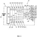
figure 3 est un schéma électrique d'un frein de stationnement conforme à l'invention utilisant un moteur électrique à six bornes.Thefigure 3 is a circuit diagram of a parking brake according to the invention using a six-terminal electric motor.
Dans la description qui suit des parties identiques, similaires ou équivalentes des différentes figures sont repérées avec les mêmes signes de référence.In the following description, identical, similar or equivalent parts of the different figures are marked with the same reference signs.
La
La tondeuse dispose de deux autres moteurs électriques repérés avec les références 20a et 20b. Il s'agit de moteurs destinés au déplacement de la tondeuse. Les moteurs de déplacement 20a, 20b sont disposés au voisinage de roues arrière motrices 22a, 22b auxquels ils sont respectivement couplés au moyen d'un réducteur mécanique 24a, 24b. Les réducteurs mécaniques permettent d'entrainer les roues motrices 22a, 22b avec une vitesse de rotation inférieure à celle des moteurs. Inversement, dans le cas d'un déplacement spontané de la tondeuse, les moteurs sont entrainés en rotation par les roues motrices à une vitesse de rotation supérieure à celle des roues motrices.The mower has two other electric motors marked with
Il convient de préciser que les moteurs de déplacement 20a, 20b peuvent entrainer les roues motrices 22a, 22b à des vitesses de rotation identiques ou différentes. Des vitesses de rotation différentes, voire des sens de rotation différents, peuvent intervenir notamment pour faciliter le déplacement de la tondeuse par exemple dans la courbe d'un virage.It should be noted that the
Les roues avant doubles 26a, 26b de la tondeuse sont des roues libres. Elles sont montées pivotantes à 360° respectivement autour d'un axe vertical, de façon à faciliter les manœuvres de la tondeuse.The double
Dans l'exemple de réalisation décrit en référence à la
La
Pour une tondeuse électrique à moteur électrique unique, c'est-à-dire une tondeuse dont le moteur de l'unité de coupe serait également couplé aux roues motrices, le moteur peut également être associé à une unité de commande selon le schéma de la
L'unité de commande 30 comprend une carte électronique 40 alimentée par la batterie 28. On peut noter que la batterie est connectée à la carte électronique 40 par l'intermédiaire d'un interrupteur S1. L'interrupteur S1 représente de manière générale le ou les interrupteurs susceptibles de mettre sous tension ou hors tension la tondeuse électrique et notamment les moteurs de déplacement 20a, 20b de la tondeuse. Il s'agit, par exemple, d'un interrupteur général de mise sous tension/hors tension, actionnable par l'utilisateur. Il est alors situé, par exemple, sur une interface de l'unité de commande 30 visible à la
La carte électronique 40 pilote une pluralité de transistors de puissance. Il s'agit, par exemple, de transistors de type MOSFET (transistor à effet de champ métal-oxyde-semi-conducteur). Les transistors sont repérés avec les références Q1 à Q6 et sont reliés aux bornes 41, 42 et 43 du moteur 20a, 20b. Dans l'exemple de la
La carte électronique 40 connectée aux grilles des transistors, permet de commander l'alimentation successive de différents bobinages 51, 52, 53 du stator du moteur. Il s'agit de mettre successivement l'un des transistors Q2, Q4 et Q6 relié à la borne positive de la batterie et l'un des transistors Q1, Q3 et Q5 relié à la borne négative de la batterie dans un état passant, et de maintenir les autres transistors dans un état bloqué. Les transistors sont mis dans un état conducteur ou bloqué selon une séquence adaptée à la commande souhaitée de rotation du rotor du moteur. L'alimentation successive de différents groupes de bobinages 51, 52, 53 du stator permet en effet de créer un champ magnétique tournant qui entraine le rotor à aimants permanents du moteur 20a, 20b en rotation.The
La référence R désigne une résistance électrique de très faible valeur, en série avec les transistors et destinée à mesurer le courant qui traverse les différents bobinages du moteur. La mesure de ce courant est exploitée par la carte 40 pour déterminer la position effective du rotor du moteur et pour synchroniser les champs magnétiques tournants avec la position du rotor.The reference R denotes an electrical resistance of very low value, in series with the transistors and intended to measure the current flowing through the different windings of the motor. The measurement of this current is used by the
La carte électronique 40 permet de la même façon de piloter le deuxième moteur de déplacement, non représenté, avec un jeu de transistors de puissance comparable aux transistors Q1 à Q6 de la
Le frein de stationnement de la tondeuse comprend deux commutateurs K1 et K2 électromécaniques également connectés aux bornes 41, 42, 43 du moteur 20a, 20b. Les commutateurs K1 et K2 présentent chacun une première borne commune 63 reliée à l'une des bornes du moteur, en l'occurrence la borne 43. Le premier commutateur K1 présente en outre une deuxième borne 61 relié à une autre borne 41 du moteur et une borne libre 71. De la même façon le deuxième commutateur K2 présente une deuxième borne 62 reliée à la troisième borne 42 du moteur et une borne libre 72.The parking brake of the mower comprises two electromechanical switches K1 and K2 also connected to the
Chaque commutateur est pourvu d'un électroaimant de commande L1, L2 relié à la batterie 28 par l'intermédiaire de l'interrupteur S1.Each switch is provided with a control electromagnet L1, L2 connected to the
Lorsque l'interrupteur S1 est fermé, la tondeuse est sous tension et les électroaimants 72 des commutateurs K1 et K2 sont alimentés. Les électroaimants agissent sur un contacteur qui relie respectivement la borne commune 63 des commutateurs à leur borne libre 71, 72. Dans ce cas, le frein est inactif. Les bornes 41, 42 et 43 sont alimentées par les transistors Q1 à Q6 conformément au pilotage de la carte électronique 40.When the switch S1 is closed, the mower is energized and the
Lorsque l'interrupteur S1 est ouvert, comme le montre la
Ainsi, lorsque l'interrupteur S1 est ouvert, les bornes 41, 42 et 43 du moteur se trouvent deux à deux en court-circuit. Dans cet état, une éventuelle rotation spontanée du rotor à aimants permanents du moteur électrique 20a, 20b, devant les bobinages du stator, conduit les bobinages 51, 52, 53 à générer un champ de freinage. Ce champ a pour effet de créer un couple résistant qui s'oppose à la rotation du rotor et donc des roues couplées au moteur. L'énergie fournie au rotor par les roues motrices est dissipée dans les bobinages.Thus, when the switch S1 is open, the
Il convient de préciser que l'utilisation d'un seul commutateur ne mettant en court-circuit que deux des bornes du moteur, est également envisageable, avec toutefois une efficacité de freinage réduite, créant au niveau des roues un couple résistant plus faible.It should be noted that the use of a single switch shorting only two of the motor terminals, is also possible, but with a reduced braking efficiency, creating a lower resistance at wheel level.
Par ailleurs, les deux commutateurs K1 et K2 peuvent être remplacés par un unique relais à contacteurs multiples.In addition, the two switches K1 and K2 can be replaced by a single relay with multiple contactors.
Enfin, les commutateurs K1 et K2, électromécaniques, peuvent être remplacés par des commutateurs électroniques, remplissant la même fonction de court-circuiter le moteur en l'absence d'alimentation.Finally, the electromechanical switches K1 and K2 can be replaced by electronic switches, fulfilling the same function of short-circuiting the motor in the absence of power supply.
La
La
Le moteur 20a, 20b est alimenté par l'intermédiaire de douze transistors de puissance. Six transistors Q2, Q4, Q6, Q8, Q10 et Q12 sont connectés à la borne positive de la batterie 28 et six transistors de puissance Q1, Q3, Q5, Q7, Q9 et Q11 sont connectés à la borne négative de la batterie 28. Les transistors sont pilotés par la carte électronique 40 et fournissent respectivement des courants d'alimentation aux bobinages 51, 52, 53, 54, 55, 56 du moteur 20a, 20b.The
Le frein de stationnement électromagnétique met en jeu cinq commutateurs électromécaniques K1, K2, K3, K4, K5 du type normalement fermés, et maintenus ouverts lorsque leur commande respective est alimentée par la batterie 28.The electromagnetic parking brake involves five electromechanical switches K1, K2, K3, K4, K5 of the normally closed type, and kept open when their respective command is powered by the
Chaque commutateur comprend un contacteur relié à une première borne 81, 83, 85, 87 du commutateur. Lorsque les commutateurs K1, K2, K3, K4, K5 sont sous tension, le contacteur de chaque commutateur relie respectivement la première borne à une borne libre 71, 72, 73, 74, 75. Le circuit électrique du frein est ouvert et le frein est inactif.Each switch comprises a contactor connected to a
En revanche, lorsque les commutateurs K1, K2, K3, K4, K5 ne sont pas sous tension, c'est-à-dire lorsque l'interrupteur S1 est ouvert, le contracteur de chaque commutateur relie la première borne 81, 83, 85, 87, 89 du commutateur respectivement à une deuxième borne 80, 82, 84, 86, 88 du commutateur. La première borne et la deuxième borne de chaque commutateur sont respectivement connectées à deux bornes successives ou tout au moins distinctes du moteur. Ainsi les bornes 80, 81 du premier commutateur se trouvent connectées aux bornes 41 et 42 du moteur, les bornes 82, 83 du deuxième commutateur se trouvent connectées aux bornes 42 et 43 du moteur, les bornes 84 et 85 du troisième commutateur se trouvent connectées aux bornes 44 et 46 du moteur, les bornes 86, 87 du quatrième commutateur se trouvent connectées aux bornes 42 et 43 du moteur, et les bornes 88 et 89 du cinquième commutateur se trouvent connectées aux bornes 44 et 46 du moteur. Dans cet état, les bornes successives du moteur se trouvent deux à deux en court-circuit. Il en va de même pour les bobinages connectés entre les bornes. Le moteur est alors utilisé comme un frein, d'une manière comparable à celle exposée en relation avec la
Il convient de préciser qu'il est également possible de ne court-circuiter qu'une partie des bobinages du moteur, avec toutefois une efficacité de freinage réduite.It should be noted that it is also possible to short-circuit only a part of the motor windings, but with a reduced braking efficiency.
Selon une variante à la réalisation de la
Selon un schéma comparable aux
Claims (12)
- An electric mower (10) comprising a cutting unit (12), at least one battery (28) for an electrical power supply for the mower, at least two driving wheels (22a, 22b) and at least one electric motor, with permanent magnets (16, 20a, 20b) that is coupled to the driving wheels, characterised by an electromagnetic parking brake comprising the electric motor (20a, 20b).
- An electric mower according to claim 1 comprising at least one reducing transmission (24a, 24b) connected between the motor (20a, 20b) and the driving wheels (22a, 22b), the electric motor is coupled to the driving wheels by way of the reducing transmission.
- An electric mower according to claim 1 or claim 2 wherein the electromagnetic parking brake comprises at least one switch (K1, K2, K3, K4, K5) having an open state and a closed state, the switch being connected to terminals (41, 42, 43, 44, 45, 46) of at least one winding (51, 52, 53, 54, 55, 56) of the electric motor and configured to connect the terminals of said winding in a short-circuit in the closed state.
- An electric mower according to claim 3 wherein the electric motor comprises a plurality of stator windings (51, 52, 53, 54, 55, 56), the switch (K1, K2, K3, K4, K5) being connected to the terminals (41, 42, 43, 44, 45, 46) of at least one of the windings of the stator.
- An electric mower according to claim 4 wherein the electromagnetic parking brake comprises a plurality of switches (K1, K2, K3, K4, K5) configured to short-circuit all of the windings of the motor (51, 52, 53, 54, 55, 56) when the brake is active.
- An electric mower according to one of the preceding claims wherein the electric motor (20a, 20b) is a three-phase motor having three stator windings (51, 52, 53) connected to three terminals (41, 42, 43) of the electric motor and wherein the parking brake comprises two switches (K1, K2) each having a first common terminal (63) connected to a first terminal (43) of the motor and a second terminal (61, 62) respectively connected to a second and a third terminal (42, 43) of the electric motor, the first and second terminals of each switch (K1, K2) being respectively brought into electrical contact in the closed position of said switch.
- An electric mower according to any one of claims 3 to 6 wherein the electromagnetic parking brake Is a brake with automatic triggering when the mower is switched off.
- An electric mower according to claim 7 wherein the switch (K1, K2) is of the type which is closed in the rest state, a control (L1, L2) of the switch being connected to the battery (28) by way of an electrical power switch (S1) of the mower such as to keep the switch (K1, K2) in the open state when the mower is powered and to cause an automatic return to the closed state when the mower is switched off.
- An electric mower according to one of claims 3 to 8 wherein the switch (K1, K2) is a transistor switch of MOSFET type.
- An electric mower according to one of the preceding claims wherein the electric motor is a motor (16) for driving the cutting unit.
- An electric mower according to one of claims 1 to 9 comprising an electric motor (16) for driving the cutting unit, that is separate from the motor (20a, 20b) coupled to the driving wheels (22a, 22b).
- An electric mower according to claim 11 comprising two electric motors (20a, 20b) respectively coupled to the two rear driving wheels (22a, 22b) and wherein the electromagnetic parking brake comprises the two electric motors (20a, 20b) coupled to the rear driving wheels.
Applications Claiming Priority (2)
| Application Number | Priority Date | Filing Date | Title |
|---|---|---|---|
| FR1557703A FR3039967B1 (en) | 2015-08-13 | 2015-08-13 | ELECTRICAL AGRICULTURAL MOWER WITH ELECTROMAGNETIC PARKING BRAKE. |
| PCT/FR2016/051541 WO2017025667A1 (en) | 2015-08-13 | 2016-06-23 | Electric mower with electromagnetic parking brake |
Publications (2)
| Publication Number | Publication Date |
|---|---|
| EP3334270A1 EP3334270A1 (en) | 2018-06-20 |
| EP3334270B1 true EP3334270B1 (en) | 2019-11-27 |
Family
ID=54260993
Family Applications (1)
| Application Number | Title | Priority Date | Filing Date |
|---|---|---|---|
| EP16745781.1A Active EP3334270B1 (en) | 2015-08-13 | 2016-06-23 | Electric lawn mower with electromagnetic parking break |
Country Status (3)
| Country | Link |
|---|---|
| EP (1) | EP3334270B1 (en) |
| FR (1) | FR3039967B1 (en) |
| WO (1) | WO2017025667A1 (en) |
Family Cites Families (4)
| Publication number | Priority date | Publication date | Assignee | Title |
|---|---|---|---|---|
| DE1931109B2 (en) * | 1969-06-19 | 1975-07-03 | As-Motor Gmbh U. Co Kg, 7163 Oberrot | Electric brake for electric lawnmower - has switches and relay to short-circuit armature simultaneously with interruption of main circuit |
| DE4227487A1 (en) * | 1992-08-20 | 1994-02-24 | Gardena Kress & Kastner Gmbh | Cutting device, especially thread cutter |
| DE102007056319A1 (en) * | 2007-11-22 | 2009-05-28 | Andreas Stihl Ag & Co. Kg | Tool head i.e. thread cutting head, for free cutting device, has electromechanical unwinding device readjusting free length of end section of cutting thread and provided with energy source, control unit and electromechanical actuator |
| JP5401682B2 (en) * | 2008-04-18 | 2014-01-29 | 株式会社 神崎高級工機製作所 | Electric ground work vehicle |
-
2015
- 2015-08-13 FR FR1557703A patent/FR3039967B1/en not_active Expired - Fee Related
-
2016
- 2016-06-23 WO PCT/FR2016/051541 patent/WO2017025667A1/en active Application Filing
- 2016-06-23 EP EP16745781.1A patent/EP3334270B1/en active Active
Non-Patent Citations (1)
| Title |
|---|
| None * |
Also Published As
| Publication number | Publication date |
|---|---|
| FR3039967A1 (en) | 2017-02-17 |
| WO2017025667A1 (en) | 2017-02-16 |
| FR3039967B1 (en) | 2017-07-28 |
| EP3334270A1 (en) | 2018-06-20 |
Similar Documents
| Publication | Publication Date | Title |
|---|---|---|
| EP2033833B1 (en) | Secure electric braking device with permanent magnet motor and braking torque regulation | |
| CA2700473C (en) | Method for moving an aircraft on the ground | |
| US9812931B2 (en) | Apparatus for switching between wye and delta configurations in an electric motor | |
| EP1537328B1 (en) | Control device for a reversible rotating electrical machine | |
| FR2843921B1 (en) | APPARATUS FOR POWER SUPPLY IN AN ELECTRIC VEHICLE | |
| EP3393229B1 (en) | Electric mower with automatic blade unblocking and method for controlling the mower | |
| WO1983002043A1 (en) | Electric rotary machine forming particularly a speed variator or a torque converter | |
| EP0506805B2 (en) | Power unit for vehicles | |
| FR2989062A1 (en) | CROSS-FLOW MACHINE USED AS PART OF A COMBINED LANDING TRAIN SYSTEM | |
| EP2960153B1 (en) | Method for managing an electric motor | |
| WO2018065709A1 (en) | Aircraft turboprop equipped with an electrical machine | |
| US20140288750A1 (en) | Method for switching between wye and delta configurations in an electric motor | |
| US9866088B1 (en) | Combination electric generator with electric clutch | |
| WO2004100351A2 (en) | Method of controlling a polyphase, reversible rotating electrical machine for heat-engine motor vehicles | |
| EP3334270B1 (en) | Electric lawn mower with electromagnetic parking break | |
| FR2989061A1 (en) | COAXIAL CONTRAROTATIVE ENGINES FOR DIFFERENTIAL ORIENTATION OF LANDING TRAIN | |
| EP0578567B1 (en) | Speed commutation device for two electric motors with different speeds | |
| EP0018904A1 (en) | Commutatorless D.C. motor | |
| FR2807231A1 (en) | Motor vehicle starter-generator has magnet mounted on rotor shaft pulley and Hall effect sensor mounted on front bearing | |
| EP0905874B1 (en) | Brake motor comprising an asynchronous motor with capacitor and zero current brake | |
| EP4252336A1 (en) | Pump actuating device, and associated pumping system, aircraft and fuel supply method | |
| EP1665490A2 (en) | Control device for an alterno-starter, particularly for a motor vehicle | |
| FR3129044A1 (en) | METHOD FOR CONTROLLING A ROTATING ELECTRIC MACHINE IN A PASSIVE STATE | |
| BE399283A (en) |
Legal Events
| Date | Code | Title | Description |
|---|---|---|---|
| STAA | Information on the status of an ep patent application or granted ep patent |
Free format text: STATUS: THE INTERNATIONAL PUBLICATION HAS BEEN MADE |
|
| PUAI | Public reference made under article 153(3) epc to a published international application that has entered the european phase |
Free format text: ORIGINAL CODE: 0009012 |
|
| STAA | Information on the status of an ep patent application or granted ep patent |
Free format text: STATUS: REQUEST FOR EXAMINATION WAS MADE |
|
| 17P | Request for examination filed |
Effective date: 20180109 |
|
| AK | Designated contracting states |
Kind code of ref document: A1 Designated state(s): AL AT BE BG CH CY CZ DE DK EE ES FI FR GB GR HR HU IE IS IT LI LT LU LV MC MK MT NL NO PL PT RO RS SE SI SK SM TR |
|
| AX | Request for extension of the european patent |
Extension state: BA ME |
|
| RAP1 | Party data changed (applicant data changed or rights of an application transferred) |
Owner name: PELLENC |
|
| DAV | Request for validation of the european patent (deleted) | ||
| DAX | Request for extension of the european patent (deleted) | ||
| GRAP | Despatch of communication of intention to grant a patent |
Free format text: ORIGINAL CODE: EPIDOSNIGR1 |
|
| STAA | Information on the status of an ep patent application or granted ep patent |
Free format text: STATUS: GRANT OF PATENT IS INTENDED |
|
| GRAJ | Information related to disapproval of communication of intention to grant by the applicant or resumption of examination proceedings by the epo deleted |
Free format text: ORIGINAL CODE: EPIDOSDIGR1 |
|
| GRAP | Despatch of communication of intention to grant a patent |
Free format text: ORIGINAL CODE: EPIDOSNIGR1 |
|
| INTG | Intention to grant announced |
Effective date: 20190801 |
|
| INTG | Intention to grant announced |
Effective date: 20190809 |
|
| GRAS | Grant fee paid |
Free format text: ORIGINAL CODE: EPIDOSNIGR3 |
|
| GRAA | (expected) grant |
Free format text: ORIGINAL CODE: 0009210 |
|
| STAA | Information on the status of an ep patent application or granted ep patent |
Free format text: STATUS: THE PATENT HAS BEEN GRANTED |
|
| AK | Designated contracting states |
Kind code of ref document: B1 Designated state(s): AL AT BE BG CH CY CZ DE DK EE ES FI FR GB GR HR HU IE IS IT LI LT LU LV MC MK MT NL NO PL PT RO RS SE SI SK SM TR |
|
| REG | Reference to a national code |
Ref country code: GB Ref legal event code: FG4D Free format text: NOT ENGLISH |
|
| REG | Reference to a national code |
Ref country code: CH Ref legal event code: EP |
|
| REG | Reference to a national code |
Ref country code: AT Ref legal event code: REF Ref document number: 1205694 Country of ref document: AT Kind code of ref document: T Effective date: 20191215 |
|
| REG | Reference to a national code |
Ref country code: DE Ref legal event code: R096 Ref document number: 602016025120 Country of ref document: DE |
|
| REG | Reference to a national code |
Ref country code: IE Ref legal event code: FG4D Free format text: LANGUAGE OF EP DOCUMENT: FRENCH |
|
| REG | Reference to a national code |
Ref country code: NL Ref legal event code: MP Effective date: 20191127 |
|
| REG | Reference to a national code |
Ref country code: LT Ref legal event code: MG4D |
|
| PG25 | Lapsed in a contracting state [announced via postgrant information from national office to epo] |
Ref country code: LT Free format text: LAPSE BECAUSE OF FAILURE TO SUBMIT A TRANSLATION OF THE DESCRIPTION OR TO PAY THE FEE WITHIN THE PRESCRIBED TIME-LIMIT Effective date: 20191127 Ref country code: SE Free format text: LAPSE BECAUSE OF FAILURE TO SUBMIT A TRANSLATION OF THE DESCRIPTION OR TO PAY THE FEE WITHIN THE PRESCRIBED TIME-LIMIT Effective date: 20191127 Ref country code: LV Free format text: LAPSE BECAUSE OF FAILURE TO SUBMIT A TRANSLATION OF THE DESCRIPTION OR TO PAY THE FEE WITHIN THE PRESCRIBED TIME-LIMIT Effective date: 20191127 Ref country code: NL Free format text: LAPSE BECAUSE OF FAILURE TO SUBMIT A TRANSLATION OF THE DESCRIPTION OR TO PAY THE FEE WITHIN THE PRESCRIBED TIME-LIMIT Effective date: 20191127 Ref country code: NO Free format text: LAPSE BECAUSE OF FAILURE TO SUBMIT A TRANSLATION OF THE DESCRIPTION OR TO PAY THE FEE WITHIN THE PRESCRIBED TIME-LIMIT Effective date: 20200227 Ref country code: GR Free format text: LAPSE BECAUSE OF FAILURE TO SUBMIT A TRANSLATION OF THE DESCRIPTION OR TO PAY THE FEE WITHIN THE PRESCRIBED TIME-LIMIT Effective date: 20200228 Ref country code: FI Free format text: LAPSE BECAUSE OF FAILURE TO SUBMIT A TRANSLATION OF THE DESCRIPTION OR TO PAY THE FEE WITHIN THE PRESCRIBED TIME-LIMIT Effective date: 20191127 Ref country code: BG Free format text: LAPSE BECAUSE OF FAILURE TO SUBMIT A TRANSLATION OF THE DESCRIPTION OR TO PAY THE FEE WITHIN THE PRESCRIBED TIME-LIMIT Effective date: 20200227 |
|
| PG25 | Lapsed in a contracting state [announced via postgrant information from national office to epo] |
Ref country code: RS Free format text: LAPSE BECAUSE OF FAILURE TO SUBMIT A TRANSLATION OF THE DESCRIPTION OR TO PAY THE FEE WITHIN THE PRESCRIBED TIME-LIMIT Effective date: 20191127 Ref country code: HR Free format text: LAPSE BECAUSE OF FAILURE TO SUBMIT A TRANSLATION OF THE DESCRIPTION OR TO PAY THE FEE WITHIN THE PRESCRIBED TIME-LIMIT Effective date: 20191127 Ref country code: IS Free format text: LAPSE BECAUSE OF FAILURE TO SUBMIT A TRANSLATION OF THE DESCRIPTION OR TO PAY THE FEE WITHIN THE PRESCRIBED TIME-LIMIT Effective date: 20200327 |
|
| PG25 | Lapsed in a contracting state [announced via postgrant information from national office to epo] |
Ref country code: AL Free format text: LAPSE BECAUSE OF FAILURE TO SUBMIT A TRANSLATION OF THE DESCRIPTION OR TO PAY THE FEE WITHIN THE PRESCRIBED TIME-LIMIT Effective date: 20191127 |
|
| PG25 | Lapsed in a contracting state [announced via postgrant information from national office to epo] |
Ref country code: CZ Free format text: LAPSE BECAUSE OF FAILURE TO SUBMIT A TRANSLATION OF THE DESCRIPTION OR TO PAY THE FEE WITHIN THE PRESCRIBED TIME-LIMIT Effective date: 20191127 Ref country code: DK Free format text: LAPSE BECAUSE OF FAILURE TO SUBMIT A TRANSLATION OF THE DESCRIPTION OR TO PAY THE FEE WITHIN THE PRESCRIBED TIME-LIMIT Effective date: 20191127 Ref country code: EE Free format text: LAPSE BECAUSE OF FAILURE TO SUBMIT A TRANSLATION OF THE DESCRIPTION OR TO PAY THE FEE WITHIN THE PRESCRIBED TIME-LIMIT Effective date: 20191127 Ref country code: PT Free format text: LAPSE BECAUSE OF FAILURE TO SUBMIT A TRANSLATION OF THE DESCRIPTION OR TO PAY THE FEE WITHIN THE PRESCRIBED TIME-LIMIT Effective date: 20200419 Ref country code: RO Free format text: LAPSE BECAUSE OF FAILURE TO SUBMIT A TRANSLATION OF THE DESCRIPTION OR TO PAY THE FEE WITHIN THE PRESCRIBED TIME-LIMIT Effective date: 20191127 Ref country code: ES Free format text: LAPSE BECAUSE OF FAILURE TO SUBMIT A TRANSLATION OF THE DESCRIPTION OR TO PAY THE FEE WITHIN THE PRESCRIBED TIME-LIMIT Effective date: 20191127 |
|
| REG | Reference to a national code |
Ref country code: DE Ref legal event code: R097 Ref document number: 602016025120 Country of ref document: DE |
|
| PG25 | Lapsed in a contracting state [announced via postgrant information from national office to epo] |
Ref country code: SK Free format text: LAPSE BECAUSE OF FAILURE TO SUBMIT A TRANSLATION OF THE DESCRIPTION OR TO PAY THE FEE WITHIN THE PRESCRIBED TIME-LIMIT Effective date: 20191127 Ref country code: SM Free format text: LAPSE BECAUSE OF FAILURE TO SUBMIT A TRANSLATION OF THE DESCRIPTION OR TO PAY THE FEE WITHIN THE PRESCRIBED TIME-LIMIT Effective date: 20191127 |
|
| PGFP | Annual fee paid to national office [announced via postgrant information from national office to epo] |
Ref country code: GB Payment date: 20200629 Year of fee payment: 5 |
|
| REG | Reference to a national code |
Ref country code: AT Ref legal event code: MK05 Ref document number: 1205694 Country of ref document: AT Kind code of ref document: T Effective date: 20191127 |
|
| PLBE | No opposition filed within time limit |
Free format text: ORIGINAL CODE: 0009261 |
|
| STAA | Information on the status of an ep patent application or granted ep patent |
Free format text: STATUS: NO OPPOSITION FILED WITHIN TIME LIMIT |
|
| 26N | No opposition filed |
Effective date: 20200828 |
|
| PG25 | Lapsed in a contracting state [announced via postgrant information from national office to epo] |
Ref country code: AT Free format text: LAPSE BECAUSE OF FAILURE TO SUBMIT A TRANSLATION OF THE DESCRIPTION OR TO PAY THE FEE WITHIN THE PRESCRIBED TIME-LIMIT Effective date: 20191127 Ref country code: PL Free format text: LAPSE BECAUSE OF FAILURE TO SUBMIT A TRANSLATION OF THE DESCRIPTION OR TO PAY THE FEE WITHIN THE PRESCRIBED TIME-LIMIT Effective date: 20191127 Ref country code: SI Free format text: LAPSE BECAUSE OF FAILURE TO SUBMIT A TRANSLATION OF THE DESCRIPTION OR TO PAY THE FEE WITHIN THE PRESCRIBED TIME-LIMIT Effective date: 20191127 |
|
| PG25 | Lapsed in a contracting state [announced via postgrant information from national office to epo] |
Ref country code: IT Free format text: LAPSE BECAUSE OF FAILURE TO SUBMIT A TRANSLATION OF THE DESCRIPTION OR TO PAY THE FEE WITHIN THE PRESCRIBED TIME-LIMIT Effective date: 20191127 Ref country code: MC Free format text: LAPSE BECAUSE OF FAILURE TO SUBMIT A TRANSLATION OF THE DESCRIPTION OR TO PAY THE FEE WITHIN THE PRESCRIBED TIME-LIMIT Effective date: 20191127 |
|
| REG | Reference to a national code |
Ref country code: CH Ref legal event code: PL |
|
| PG25 | Lapsed in a contracting state [announced via postgrant information from national office to epo] |
Ref country code: LU Free format text: LAPSE BECAUSE OF NON-PAYMENT OF DUE FEES Effective date: 20200623 |
|
| REG | Reference to a national code |
Ref country code: BE Ref legal event code: MM Effective date: 20200630 |
|
| PG25 | Lapsed in a contracting state [announced via postgrant information from national office to epo] |
Ref country code: IE Free format text: LAPSE BECAUSE OF NON-PAYMENT OF DUE FEES Effective date: 20200623 Ref country code: CH Free format text: LAPSE BECAUSE OF NON-PAYMENT OF DUE FEES Effective date: 20200630 Ref country code: LI Free format text: LAPSE BECAUSE OF NON-PAYMENT OF DUE FEES Effective date: 20200630 |
|
| PG25 | Lapsed in a contracting state [announced via postgrant information from national office to epo] |
Ref country code: BE Free format text: LAPSE BECAUSE OF NON-PAYMENT OF DUE FEES Effective date: 20200630 |
|
| GBPC | Gb: european patent ceased through non-payment of renewal fee |
Effective date: 20210623 |
|
| PG25 | Lapsed in a contracting state [announced via postgrant information from national office to epo] |
Ref country code: GB Free format text: LAPSE BECAUSE OF NON-PAYMENT OF DUE FEES Effective date: 20210623 |
|
| PG25 | Lapsed in a contracting state [announced via postgrant information from national office to epo] |
Ref country code: TR Free format text: LAPSE BECAUSE OF FAILURE TO SUBMIT A TRANSLATION OF THE DESCRIPTION OR TO PAY THE FEE WITHIN THE PRESCRIBED TIME-LIMIT Effective date: 20191127 Ref country code: MT Free format text: LAPSE BECAUSE OF FAILURE TO SUBMIT A TRANSLATION OF THE DESCRIPTION OR TO PAY THE FEE WITHIN THE PRESCRIBED TIME-LIMIT Effective date: 20191127 Ref country code: CY Free format text: LAPSE BECAUSE OF FAILURE TO SUBMIT A TRANSLATION OF THE DESCRIPTION OR TO PAY THE FEE WITHIN THE PRESCRIBED TIME-LIMIT Effective date: 20191127 |
|
| PG25 | Lapsed in a contracting state [announced via postgrant information from national office to epo] |
Ref country code: MK Free format text: LAPSE BECAUSE OF FAILURE TO SUBMIT A TRANSLATION OF THE DESCRIPTION OR TO PAY THE FEE WITHIN THE PRESCRIBED TIME-LIMIT Effective date: 20191127 |
|
| PGFP | Annual fee paid to national office [announced via postgrant information from national office to epo] |
Ref country code: FR Payment date: 20230626 Year of fee payment: 8 Ref country code: DE Payment date: 20230626 Year of fee payment: 8 |