EP3334269B1 - Gathering chains for row crop harvester heads - Google Patents
Gathering chains for row crop harvester heads Download PDFInfo
- Publication number
- EP3334269B1 EP3334269B1 EP16835772.1A EP16835772A EP3334269B1 EP 3334269 B1 EP3334269 B1 EP 3334269B1 EP 16835772 A EP16835772 A EP 16835772A EP 3334269 B1 EP3334269 B1 EP 3334269B1
- Authority
- EP
- European Patent Office
- Prior art keywords
- bristles
- row unit
- gathering
- row
- gathering chain
- Prior art date
- Legal status (The legal status is an assumption and is not a legal conclusion. Google has not performed a legal analysis and makes no representation as to the accuracy of the status listed.)
- Active
Links
- 230000000712 assembly Effects 0.000 claims description 28
- 238000000429 assembly Methods 0.000 claims description 28
- 238000003306 harvesting Methods 0.000 claims description 19
- 240000008042 Zea mays Species 0.000 description 32
- 235000005824 Zea mays ssp. parviglumis Nutrition 0.000 description 32
- 235000002017 Zea mays subsp mays Nutrition 0.000 description 32
- 235000005822 corn Nutrition 0.000 description 32
- 210000005069 ears Anatomy 0.000 description 14
- 239000000463 material Substances 0.000 description 11
- 230000009418 agronomic effect Effects 0.000 description 6
- 239000011236 particulate material Substances 0.000 description 4
- 229920001169 thermoplastic Polymers 0.000 description 4
- 239000004416 thermosoftening plastic Substances 0.000 description 4
- 229920001971 elastomer Polymers 0.000 description 3
- 229910001092 metal group alloy Inorganic materials 0.000 description 3
- JOYRKODLDBILNP-UHFFFAOYSA-N Ethyl urethane Chemical compound CCOC(N)=O JOYRKODLDBILNP-UHFFFAOYSA-N 0.000 description 2
- 239000000806 elastomer Substances 0.000 description 2
- 239000010903 husk Substances 0.000 description 2
- 238000000034 method Methods 0.000 description 2
- 239000000203 mixture Substances 0.000 description 2
- 239000004033 plastic Substances 0.000 description 2
- 229920003023 plastic Polymers 0.000 description 2
- 230000000717 retained effect Effects 0.000 description 2
- 241000196324 Embryophyta Species 0.000 description 1
- 244000068988 Glycine max Species 0.000 description 1
- 235000010469 Glycine max Nutrition 0.000 description 1
- 241001124569 Lycaenidae Species 0.000 description 1
- 239000004433 Thermoplastic polyurethane Substances 0.000 description 1
- 238000005461 lubrication Methods 0.000 description 1
- 238000012986 modification Methods 0.000 description 1
- 230000004048 modification Effects 0.000 description 1
- 229920002635 polyurethane Polymers 0.000 description 1
- 239000004814 polyurethane Substances 0.000 description 1
- 239000003351 stiffener Substances 0.000 description 1
- 229920002725 thermoplastic elastomer Polymers 0.000 description 1
- 229920002803 thermoplastic polyurethane Polymers 0.000 description 1
Images


Classifications
-
- A—HUMAN NECESSITIES
- A01—AGRICULTURE; FORESTRY; ANIMAL HUSBANDRY; HUNTING; TRAPPING; FISHING
- A01D—HARVESTING; MOWING
- A01D45/00—Harvesting of standing crops
- A01D45/02—Harvesting of standing crops of maize, i.e. kernel harvesting
- A01D45/021—Cornheaders
- A01D45/023—Gathering chains of belts
-
- A—HUMAN NECESSITIES
- A01—AGRICULTURE; FORESTRY; ANIMAL HUSBANDRY; HUNTING; TRAPPING; FISHING
- A01D—HARVESTING; MOWING
- A01D47/00—Headers for topping of plants, e.g. stalks with ears
Definitions
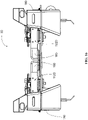
- FIGs. 1-3 An example of a conventional combine 10 is shown in FIGs. 1-3 having a conventional head 20 attached for harvesting row crops, such as corn.
- the row crop head 20 may be referred to as a "corn head” for simplicity.
- Row crop heads 20 include a plurality of conical shaped crop dividers 22 which extend forwardly and diverge rearwardly.
- Row unit assemblies 30 are disposed between the adjacent dividers where the rearwardly diverging dividers 22 nearly converge.
- the row crop head or corn head 20 is illustrated with twelve row unit assemblies 30 (e.g., a 12-row corn head) but it should be understood that row crop heads such as corn heads typically range from four rows to twenty-four rows or more.
- the corn head 20 is positioned with the dividers 22 positioned between adjacent corn rows 12 and below the ears 14 on the cornstalks 16.
- the conical, rearwardly diverging shape of the dividers 22 cause the cornstalks 16 within each row 12 to be guided and directed into the row unit assemblies 30 between the adjacent dividers 22.
- the row unit assemblies 30 separate the ears 14 from the cornstalks 16 and convey the separated ears toward the trough 23 and cross-auger 24.
- the cross-auger 24 augers the separated ears 14 within the trough 23 toward the opening 27 of the feederhouse 26 in the middle of the corn header 20.
- the feederhouse 26 conveys the ears 14 into the interior of the combine where the corn kernels are separated from remaining portions of the cornstalks, husks and corncob. Within the combine, the separated kernels pass over a series of screens which separates unwanted crop material and other residue from the kernels. The clean grain is then carried by elevators to a clean grain holding tank while the corncobs, leaves, husks and cornstalks which entered the combine are chopped and discharged through the rear of the combine and mix with the cornstalks that pass under the combine.
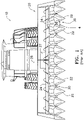
- each row unit 30 includes a pair of gathering chains 32, 34 with outwardly extending lugs 36.
- the gathering chains 32, 34 are continuous loops that extend around drive sprockets 38 and idler sprockets 39 ( FIG. 5 ). Rotation of the drive sprockets 38 causes the gathering chains 32, 34 to rotate in adjacent parallel paths such that as the combine 10 drives forwardly through the field, the outwardly extending lugs 36 draw the cornstalks 16 into the row unit 30.
- Below the rotating gathering chains is a pair of spaced stripper plates 40, 42.
- the stripper plates 40, 42 are spaced sufficiently apart to define a slot 44 between them which defines a longitudinal path of travel 111 along which corn stalks pass as the row unit moves forwardly through a corn field harvesting corn.
- the slot 44 is sufficiently wide to permit the corn stalks 16 to enter but which is sufficiently narrow so that the corn ears 14 cannot pass through.
- a pair of rapidly rotating stalk rolls 50, 52 are positioned below stripper plates 40, 42.
- the rotating stalk rolls 50, 52 rapidly pull the corn stalks 16 downwardly through the slot 44 between the stripper plates 40, 42 such that when the corn ears 14 engage the stripper plates 40, 42, the ears 14 are pulled or stripped from the cornstalks 16.
- the cornstalk 16 is pulled downwardly through the slot 44 and is returned to the field below the header 20 as the combine drives forwardly ( FIG. 2 ).
- the stripped ears 14 which remain on the stripper plates 40, 42 after the cornstalk 16 is pulled through the slot 44 are then conveyed by the lugs 36 of the gathering chains 32, 34 upwardly and rearwardly to the trough 23 and cross-auger 24.
- the cross-auger 24 augers the ears 14 within the trough to the feederhouse 26, and the feederhouse 26 feeds the ears 14 into the interior of the combine for shelling and separating the kernels from the corncob as is known in the art.
- German patent publication DE8814148U1 discloses a device for harvesting grains in which feed chains are provided with flexible plates that extend outwardly over picking gap.
- the flexible plates permit the crop stalk to be pulled downwardly through the flexible plates while at the same time the flexible plates capture loose grain preventing the loose grain from falling to the ground surface through the picking gap.
- FIGS 1- 18 relate to embodiments and examples of the prior art which are not covered by the claims.
- the present disclosure is generally directed toward a substantially continuous conveying surface designated generally across all the various embodiments illustrated in FIGs. 7-25 by reference numeral 100.
- the substantially continuous conveying surface 100 is achieved by a series of lateral extensions designated generally by reference numeral 200 which extend laterally outwardly from each of the pair of gathering chains 110 of the row unit assembly 30 of the row crop head 20.
- the gathering chains disclosed herein are particularly suitable for use on corn head, the features and advantages of the gathering chain may be equally suitable for other types of heads for harvesting other types of row crops.
- the lateral extensions 200 extend sufficiently laterally outwardly from each of the pair of gathering chains 110 in sufficiently close end to end relation or in overlapping relation to effectively close off the area which defines the path of travel 111 approximately along the centerline of the incoming crop into the row unit assembly 30 as the combine drives forwardly through the field harvesting the crop.
- the individual kernels and small crop pieces are captured by the lateral extensions 200 and conveyed into the head 20 so they cannot fall to the ground below the head resulting in reduced yield of the crop available for harvest.
- the combination of the gathering chains 110 with the lateral extensions 200 are referred to as gathering chain assemblies 112 and are differentiated among the various embodiments by suffix letters A-F and the corresponding parts of each of the chain gathering assemblies 112 are similarly designated by suffix letters A-F.
- the conveying surface 100 of the gathering chain assembly 112A is created by the opposing lateral extensions 200 in the form of paddles 202A secured to a conventional gathering chain 110A constructed of chain links 114.
- the gathering chain 110A and its chain links 114 are sized to extend around and receive the drive sprocket 38 and idler sprocket 39 of a row unit 30 of a head 20.
- the size of the gather chain 110A and links 114 may vary between makes and models of heads 20, and therefore the gathering chain assembly 112A is not limited to the embodiment shown and described herein.
- the links 114 of the gathering chain 110A are constructed in a conventional manner with each link 114 having a pair of upper and lower plates 116, 118 joined by pins 120 extending through rollers 122.
- Upper and lower link connecting plates 124, 126 pivotally join the individual links 114 thereby forming a continuous chain loop.
- the lateral extension 200 includes a paddle 202A attached to the gathering chain 110A by upper and lower bracket plates 204A, 206A. While not shown in FIGs. 7-9 , it should be understood that the lateral extensions 200 are attached along the entire length of the gathering chain 110A.
- the paddle 202A is secured to the gathering chain 110A, at the outer side of each lower plate 118 and each lower link connecting plate 16 as best illustrated in FIG. 9 . It should be appreciated that, paddle 202A may be attached at any other interval, e.g., every other link 114.
- the specific number and size of the paddles 202A, the interval at which they are attached to the gathering chain 110A and their orientation relative to one another or the gathering chain 110 may depend on the agronomic characteristics for the crop being harvested, such as the type of crop or the condition of the crop.
- the paddles 202A may be oriented so that a first paddle is attached to extend substantially lateral from the roller chain while a second paddle is attached to extend substantially perpendicular to the adjacent first paddle. This is only one example of many possible combinations of the number of paddles, intervals and orientations of the present disclosure, is not intended to limit the present disclosure and is provided to demonstrate at least some of the principles of the present disclosure.
- adjacent paddles 202A may be vertically staggered or offset, but the paddles 202A may be configured so they are vertically aligned along a single plane.
- the lower bracket plate 206A may be a flat plate that is fastened, such as by pins, rivets or other connectors to the underside of the lower link plate 118.
- the upper bracket plate 204A may be fastened by pins, rivets or other connectors to the lower bracket plate 206A with the paddle 202A sandwiched therebetween.
- the bracket plates 204A, 206A may provide additional support to reduce the amount of deflection experienced by the paddle 202A.
- the bracket plates 204A, 206 may also be configured to adjust the location at which the paddle 202A will flex or bend.
- the bracket plates 204A, 206A may be shortened, such that the plates 204A, 206A do not extend as far out from the gathering chain 110A.
- the bracket plates 204A, 206A may be longer so they extend further outwardly so they terminate closer to the outer end of the paddle 202A.
- a stiffener plate 207 FIGs. 7 , 9 ) may be disposed on the underside of the paddle 202A and retained between the upper and lower bracket plats 204A, 206A.
- the paddle 202A may be constructed from any number of materials that provide the necessary functional requirements or to correspond to the agronomic characteristics of the crop being harvested, such as the type of crop or the crop condition.
- the paddle 202A may be constructed from a pliable material, such as Thermo-Plastic Urethane (TPU) or a Thermo-Plastic Elastomer (TPE).
- TPU Thermo-Plastic Urethane
- TPE Thermo-Plastic Elastomer
- the paddle 202A may also be constructed from a more rigid material such as a hard plastic or metal alloy. Generally the paddle 202A will be configured such that a plant stalk, such as a corn stalk, may pass between the paddles 202A of opposing sides of the row unit 30.
- the paddles 202A of opposing sides of the row unit 30 may be constructed of a suitably pliable material to provide the necessary deflection of the opposing paddles 202A to allow the cornstalk 12 to pass between them.
- a more rigid material such as a metal alloy, may be used to construct the paddles 202A.
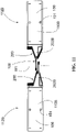
- FIGs. 10-11 illustrate an alternative embodiment of a gathering chain assembly 112B providing the conveying surface 100 created by the opposing lateral extensions 200 also in the form of paddles 202B secured to a gathering chain 110B comprising a flexible belt 150 having molded teeth 152 on an inner periphery of the belt 150.
- the belt 150 may be constructed of a rubber material including but not limited to polyurethane or a thermoplastic elastomer, such as thermoplastic polyurethane.
- the paddles 202B are shown as a molded block which can be secured directly to the flexible belt 150 by fasteners, such as pins, rivets or other connectors extending through apertures 151 in the flexible belt 150.
- the molded teeth 152 on the inner periphery of the belt 150 are configured to matingly align and cooperate with the tooth pattern of the drive sprocket 38 and idler sprocket 39. It is recognized that a belt can generally be used in lieu of a chain. Some of the advantages of a belt are that a belt will typically cost less and generates less noise than a chain and does not require lubrication.
- the various components of the row unit 30 are not shown in FIGs. 10-11 in order to better display the features of the gathering chain assembly 112B. It should be appreciated that the configuration of the sprockets and belt 150 may vary between makes and models of combine grain heads as recognized and understood by those of skill in the art.
- the paddles go all the way around the outer surface of the belt 150, such that the paddles 200B are adjacent one another and continuous along the entire length of the belt 150.
- the specific number of paddles 200B, the size of the paddles 200B, the interval at which they are positioned and their orientation relative to one another or the belt 150 may depend on the agronomic characteristics for the crop being harvested, such as the type of crop or the condition of the crop.
- the paddles 202B may oriented so that a first paddle is placed to extend substantially lateral from the belt 150 while a second paddle is positioned substantially perpendicular to the adjacent first paddle. This is only one example of many possible combinations of the number of paddles, intervals and orientations of the present disclosure, is not intended to limit the present disclosure and is provided to demonstrate at least some of the principles of the present disclosure.
- FIG. 11 is an end elevation view of the pair of adjacent gathering chain assemblies 112B showing in FIG. 10 .
- the paddles 202B are shown extending outwardly with their ends overlapping, but it should be appreciated that the paddles may be configured such that their ends are aligned along a plane.
- FIGs. 12-13 illustrate another alternative embodiment of a gathering chain assembly 112C providing the conveying surface 100 created by the opposing lateral extensions 200 also in the form of paddles 202C secured to a gathering chain 110C comprising a flexible belt 150 having molded teeth 152 on an inner periphery of the belt 150.
- the gathering chains 112C are shown arranged for mounting on a row unit 30, with the various components of the row unit 30 removed for clarity. Additionally, while not shown in FIG. 12 , it should be appreciated that the paddles 202C go all the way around the outer surface of the belt 150, such that the paddles 202C are adjacent one another and continuous along the entire length of the belt 150.
- FIG. 13 is an end elevation view of the adjacent gathering chain assemblies 112C shown in FIG. 13 .
- the paddles 202C are configured with their outer ends overlapping, but it should be appreciated that the paddles may be configured such that their ends are aligned along a plane.
- the paddles 202C includes a paddle bracket 204C comprises a channel or U-shaped recess 206 into which the paddle 202C is received between upper and lower flanges 207, 208.
- the paddle bracket 204C is configured to support the paddle 202C and limit the degree to which the paddle 202C may be bent or deflected.
- the U-shaped configuration can limit the deflection of the paddle in multiple directions. For example, the upper flange 207 located above the paddle 202C will prevent the paddle 202C from being deflected upward and the flange 208 located below the paddle 202C with prevent the paddle 202C from being deflected in a downward direction.
- FIGs. 13-14 illustrate another alternative embodiment of a gathering chain assembly 112D providing the conveying surface 100 created by the opposing lateral extensions 200 also in the form of paddles 202D secured to a gathering chain 110D comprising a flexible belt 150 having molded teeth 152 on an inner periphery of the belt 150.
- FIG. 14 is a perspective view of a single gathering chain assembly 112D.
- the gathering chain assembly 112D includes vertical tabs 160 spaced equidistantly around the belt 150, and projecting vertically above the paddles 202D.
- the vertical tabs 160 are configured to convey collected particulate material toward the rear of the row unit 30. For example, for a row unit 30 that may be used to harvest corn, once the ear of corn is removed from the stalk, the corn will land on the paddles 202D, and the vertical tabs 160 will collect and move the separated ear in a generally rearward direction as the gathering chain assembly 112D rotates.
- the tabs 160 may be integral with the belt 150 or the tabs 160 may extend from the paddle 202D or comprise an altogether separate part or component spaced between the paddles 202D.
- the tab 160 may be placed at any interval along the belt 150 and need not be equidistantly spaced.
- the specific number of tabs 160, the size of the tabs 160, the interval at which they are placed and their orientation relative to one another or the belt 150 may depend on the agronomic characteristics for the crop being harvested, such as the type of crop or the condition of the crop and therefore the embodiment shown is not intended to limit the present disclosure and is provided to demonstrate at least some of the principles of the present disclosure.
- the vertical tabs 160 may be spaced approximately eight to fifteen inches apart along the belt 150. However, if used to harvest a smaller row crop, such as soybeans, the vertical tabs 160 may need to be oriented closer together, for example, spaced approximately four to six inches apart along the belt 150.
- the vertical tabs 160 may be constructed from any number of materials that provide the necessary functional requirements.
- the vertical tabs 160 may be constructed from a pliable material, such as Thermo-Plastic Urethane (TPU) or a Thermo-Plastic Elastomer (TPE).
- TPU Thermo-Plastic Urethane
- TPE Thermo-Plastic Elastomer
- the vertical tabs 160 may also be constructed from a more rigid material such as a hard plastic or metal alloy.
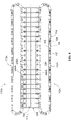
- FIGs. 15-18 are representative of row unit 30 on which the gathering chain assembly 112 may be utilized. Although the embodiment shown illustrates the gathering chain assembly 112D, any of the gathering chain assemblies 112A, 112B and 112C as well as the gathering chain assemblies 112E and 112F (discussed below) may be utilized on the row unit 30.
- the gathering chain assemblies 112 are disposed over the drive sprocket 38 and idler sprocket 39 such that the gathering chain assemblies 112 are oriented in a parallel side-by-side relationship.
- the drive sprocket 38 and idler sprocket 39 have a tooth pattern matched to that of the molded teeth 152 on the interior surface of the belt 150 (or the links 114 of the gathering chain 110 of embodiments 112A, 112F or 112G).
- a conventional spring tensioner assembly 176 may be provided to maintain the desired tension to prevent the belt 150 from slipping off the drive sprocket 38 or the idler sprocket 39.
- the tension on the gathering chain 110 may be reduced to will allow the gathering chain 110 to be dislodged from the drive sprocket 38 and/or the idler sprocket 39.
- the drive sprocket 38 may be rotated by an operatively attached shaft or gearbox. It should be appreciated that the drive sprockets 38 of the opposing gathering chain assemblies 112 rotate in opposite directions such that the opposing gathering chain assemblies 112 will work in unison to convey particulate material along the center of the row unit 30 in a generally rearward direction. For example, referring to FIG. 15 , the drive sprocket 38 of the left hand gathering chain assembly 112 rotates in a counter-clockwise direction (when viewed from above) and the drive sprocket 38 of the right hand gathering chain assembly 112 rotates in a clockwise direction (when viewed from above).
- the rotation of the drive sprockets 38 cause the opposing gathering chain assemblies 112 engaged therewith to rotate rearwardly along line 111 with respect to the forward direction of travel of the head 20.
- This rearward movement will convey the grain or other collected particulate material to the auger 24 disposed at the rear of the grain head 20.
- the auger 24 of the grain head 20 are configured to convey the particulate material from the opposing left and right ends of the head 20, toward the opening 27 of the feederhouse 26 at the center of the grain head 20, where it is then fed into the feederhouse 26 for further processing within the interior of the combine.
- the row unit 30 includes frame members 180 from which the stripper plates 40, 42 are supported (see bottom plan view of FIG. 18 ). Although the row unit 30 will include stalk rollers, the stalk rollers are excluded from FIGs. 15-18 to provide a more detailed representation of gathering chain assembly 112. The stalk rollers would be attached on the underside of the row unit 30 to a gear box (not shown) and will rotate to pull the stalk 12 downwardly between the stripper plates 40, 42 to strip the ears from the cornstalks as previously described in the Background.
- a row unit 30 on the head 20 may be converted from the conventional gathering chain 32 with lugs 36 ( FIG. 5 ) to any one of the gathering chain assemblies 112A-112F. It should be appreciated, that it may be desirable to change the drive sprocket 38 and/or idler sprocket 39 to match the links and/or tooth pattern of the gathering chain assembly embodiments 112A-112F disclosed herein.
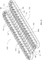
- FIGs. 19-24 an embodiment according to the invention of a conveying surface 100 is shown (only half of the conveying surface 100 is shown) wherein the conveying surface 100 comprises lateral extensions 200 in the form of a plurality of bristle blocks or brush blocks 210 wherein bristles 211 form the conveying surface 100 as opposed to paddles 202 as described in connection with the previous embodiments of the gathering chain assemblies 112A-112D.
- the gathering chain assembly 112E comprises a gathering chain 110E to which is secured the plurality of bristle blocks 210E.
- the gathering chain 110E is constructed as a conventional gathering chain comprised of individual links 114 joined together by link connecting plates 124, 126 as previously described in connection with the previous embodiment of the gathering chain 110A.
- the bristle block 210E comprise a base 212E from which the bristles 211 extend.
- the gathering chain assembly 112E is as a continuous gathering chain 110E configured to be disposed around the drive sprocket 38 and idler sprocket 39 of the row unit 30, with the bristle blocks 210E disposed around the outer periphery of the gathering chain 110E as in all the other embodiments of the gathering chain assemblies 112A-112D previously described.
- a mounting tab 130 is attached to the outer side of the bottom link connecting plate 126. It should be appreciated, however, that mounting tab 130 could also extend from the outer side of the top link connecting plate 124.
- the bristle block 210E is removably attached to the mounting tab 130.
- the base 212E of the bristle block 210E has a top side 220, a bottom side 222, a front side 224, a back side 226, a left side 228 and a right side 230.
- the plurality of bristles 211 extend from the front side 224 of the base 212E.
- the bristles 211 are sufficiently long such that they extend from the front side 224 of the base 212E from each of the adjacently disposed gathering chain assemblies 112E of the row unit 30 such that the ends of the bristles 211 are sufficiently close to form the conveying surface 100 to effectively close off or cover the area which defines the path 111 approximately along the centerline of the incoming crop into the row unit assembly 30 as the combine drives forwardly through the field harvesting the crop.
- the back side 226 of the base 212E may include a cavity 232 into which the mounting tab 130 is matingly received. As mounting tab 130 is inserted into the cavity 232, it depresses a resilient detent 234. When the mounting tab 130 reaches the end of its travel inside the cavity 232, resilient detent 234 returns to its original position. A protrusion 236 is positioned within an aperture (not shown) of mounting tab 130. In this manner, the base 212 is retained on the gathering chain 110E during operation, but can also be removed by a user after a certain amount of wear or if a different lateral extension 200 is desired.
- the base 212 may be secured to the gathering chain 110E in any other suitably rigid manner, including, for example using fasteners such as rivets or threaded fasteners, such as a screw or bolt, extending through the base 212 through the mounting tab 130.
- the bristles 211 may provide an advantage over the paddles 202 described in connection with the previous embodiments 112A-112D by allowing debris to pass through the bristles 211 onto the ground while still capturing kernels that may result from butt shelling and impact during harvesting operations.
- a top row of bristles 211-1 is disposed above a bottom row of bristles 211-2 with respect to the horizontal axis of the base 212.
- the bristles 211 may be disposed in a generally cylindrical groups at various intervals and spacing. It should be appreciated, however, that the shape of each bristle group and the number of bristles in each group may vary depending on the needs of the crop being harvested.
- the top row of bristles 211-1 are configured in an arc shape such that the bristle groups at the interior of the bristle block 210F extend further outward than the bristle groups toward the end of bristle block 210F.
- the bristle groups of the top row 111-1 and bottom row are generally the same length with respect to the amount in which they extend into the corn stalk slot. In this manner, unwanted dirt and debris may more easily pass through the bristles and the stripper slot 44 to the ground.
- FIG. 23 illustrates another embodiment of a conveying surface 100 (only half of the conveying surface 100 is shown) comprising a gathering chain assembly 112G.
- the gathering chain assembly 112G comprises a gathering chain 110G constructed of a plurality of individual links 114 joined together by link connecting plates 124, 126 as described in connection with the previous embodiments of the gathering chain 110A and 110E.
- the gathering chain 112G includes a plurality of bristle blocks 210G having a base 212G from which the bristles 211 extend.
- the gathering chain assembly 112G comprises a continuous gathering chain 110G configured to be disposed around the drive sprocket 38 and idler sprocket 39 of the row unit 30, with the bristle blocks 210G disposed around the outer periphery of the gathering chain 110G as in all the other embodiments of the gathering chain assemblies 112A-112F previously described.
- the top and bottom link connectors 124, 126 include outwardly projecting flanges 125 with apertures 127 adapted to receive top and bottom tabs, respectively of the bristle block 210G.
- FIGs 24-25 which are top and bottom perspective views, respectively of the bristle block 210G, a flexible top tab 240 is received within the aperture 127 of the top link connector 124 and the bottom tab 242 is received within the aperture 127 of the bottom link connector 126.
- the bottom tab 242 is positioned in the aperture 127 of the bottom link connector 126 and the top tab 240 is pushed inwardly causing the top tab 240 to deflect until it snaps into the aperture 127 of the top link connector 124.
- the bristle block 210G includes a top row of longer bristles 211-1 and a bottom row of shorter bristles 211-2.
- all the bristles 211-1, 211-2 may be of the same length.
- the top row of bristles 211-1 may be elevated or offset from the bottom row of bristles 211-2 such that they extend further into the corn stalk slot.
- an opposing gathering chain assembly 112G on the other side of the row unit 30 may have bristle blocks 210 configured to be opposite the configuration of the opposing bristle blocks, i.e., a shorter top row of bristles 111-1 and longer bottom row of bristles 111-2, such that the opposing bristles overlap or interlock.
- the specific number of bristle blocks 210 attached to the links 114 of gathering chain 110 and the interval at which they are attached to the gathering chain 110 and their orientation relative to one another or the gathering chain 110 may depend on the agronomic characteristics for the crop being harvested, such as the type of crop or the condition of the crop.
- certain aspects of the bristles disposed on the block member may depend on the agronomic characteristics for the crop being harvested, such as the type of crop or the condition of the crop, including but not limited to: bristle count, bristle groups and group geometry, bristle thickness, position, length, orientation as well as the material composition of the bristle.
Description
- Modern conventional agricultural combine harvesters or "combines" utilize removable and interchangeable attachments called "headers" or "heads" which are adapted for harvesting different types of crops. An example of a
conventional combine 10 is shown inFIGs. 1-3 having aconventional head 20 attached for harvesting row crops, such as corn. For convenience, and by way of example when referring to row crop heads for harvesting corn, therow crop head 20 may be referred to as a "corn head" for simplicity.Row crop heads 20 include a plurality of conicalshaped crop dividers 22 which extend forwardly and diverge rearwardly.Row unit assemblies 30 are disposed between the adjacent dividers where the rearwardly divergingdividers 22 nearly converge. InFIG. 1 , the row crop head orcorn head 20 is illustrated with twelve row unit assemblies 30 (e.g., a 12-row corn head) but it should be understood that row crop heads such as corn heads typically range from four rows to twenty-four rows or more. - As illustrated in
FIG. 3 , during corn harvesting operations, thecorn head 20 is positioned with thedividers 22 positioned betweenadjacent corn rows 12 and below theears 14 on thecornstalks 16. It should be appreciated that as thecombine 10 drives forwardly through the field as indicated by thearrow 18 inFIG. 2 , the conical, rearwardly diverging shape of thedividers 22 cause thecornstalks 16 within eachrow 12 to be guided and directed into therow unit assemblies 30 between theadjacent dividers 22. As explained in more detail below, the row unit assemblies 30 separate theears 14 from thecornstalks 16 and convey the separated ears toward the trough 23 and cross-auger 24. Thecross-auger 24 augers theseparated ears 14 within the trough 23 toward the opening 27 of thefeederhouse 26 in the middle of thecorn header 20. Thefeederhouse 26 conveys theears 14 into the interior of the combine where the corn kernels are separated from remaining portions of the cornstalks, husks and corncob. Within the combine, the separated kernels pass over a series of screens which separates unwanted crop material and other residue from the kernels. The clean grain is then carried by elevators to a clean grain holding tank while the corncobs, leaves, husks and cornstalks which entered the combine are chopped and discharged through the rear of the combine and mix with the cornstalks that pass under the combine. - Referring to
FIGs. 4-6 , eachrow unit 30 includes a pair ofgathering chains lugs 36. Thegathering chains drive sprockets 38 and idler sprockets 39 (FIG. 5 ). Rotation of thedrive sprockets 38 causes thegathering chains combine 10 drives forwardly through the field, the outwardly extendinglugs 36 draw thecornstalks 16 into therow unit 30. Below the rotating gathering chains is a pair of spacedstripper plates stripper plates slot 44 between them which defines a longitudinal path oftravel 111 along which corn stalks pass as the row unit moves forwardly through a corn field harvesting corn. Theslot 44 is sufficiently wide to permit thecorn stalks 16 to enter but which is sufficiently narrow so that thecorn ears 14 cannot pass through. A pair of rapidly rotatingstalk rolls stripper plates - As best illustrated in
FIG. 6 , during harvesting operations, the rotatingstalk rolls corn stalks 16 downwardly through theslot 44 between thestripper plates corn ears 14 engage thestripper plates ears 14 are pulled or stripped from thecornstalks 16. As the stalk rolls 50, 52 rotate, thecornstalk 16 is pulled downwardly through theslot 44 and is returned to the field below theheader 20 as the combine drives forwardly (FIG. 2 ). The strippedears 14 which remain on thestripper plates cornstalk 16 is pulled through theslot 44 are then conveyed by thelugs 36 of thegathering chains cross-auger 24 augers theears 14 within the trough to thefeederhouse 26, and thefeederhouse 26 feeds theears 14 into the interior of the combine for shelling and separating the kernels from the corncob as is known in the art. - It should be appreciated that the action of the stalks being pulled and thrashed around by the stalk rolls and gathering chains will often cause the stalks to break such that the ears of corn fall and impact against the dividers. When the ears impact the dividers or are stripped by the stripper plates, individual kernels will often break loose from the corncob and fall through the
slot 44 between the stripper plates to the ground. Every lost kernel reduces the farmers yield and potential profits. Therefore, there is a need in the art for a gathering chain that minimizes the loss of kernels that may prematurely break loose and be lost to the ground reducing yields. - German patent publication
DE8814148U1 discloses a device for harvesting grains in which feed chains are provided with flexible plates that extend outwardly over picking gap. The flexible plates permit the crop stalk to be pulled downwardly through the flexible plates while at the same time the flexible plates capture loose grain preventing the loose grain from falling to the ground surface through the picking gap. -
Figures 1- 18 relate to embodiments and examples of the prior art which are not covered by the claims. -
FIG. 1 is a front elevation view of an embodiment of a modern conventional agricultural combine harvester with a cornhead attachment. -
FIG 2 is a side elevation view of the combine harvester and cornhead ofFIG. 1 . -
FIG 3 is the same front elevation view of the combine harvester and cornhead ofFIG. 1 , but shown in a cornfield in harvesting position. -
FIG 4 is an enlarged view of the portion of the row unit assembly circled inFIG. 1 showing parts of the row unit assembly between the crop divider points. -
FIG. 5 is a perspective view of a row unit assembly. -
FIG 6 is a partial front elevation view of the row unit assembly ofFIG. 5 depicting the relationship of the row unit relative to a cornstalk during harvesting operations. -
FIG. 7 is a perspective view of an embodiment of a gathering chain assembly in which the conveying surface includes paddles. -
FIG. 8 is a top plan view showing a pair of adjacent gathering chain assemblies ofFIG. 7 configured on a row unit. -
FIG. 9 is a bottom plan view of the gathering chain assembly ofFIG. 7 . -
FIG. 10 is a perspective view of another embodiment of a pair of gathering chain assemblies configured on a row unit in which the conveying surface includes paddles. -
FIG. 11 is an end view of the pair of gathering chain assemblies ofFIG. 10 . -
FIG. 12 is a perspective view of another embodiment of a pair of gathering chain assemblies configured on a row unit in which the conveying surface includes paddles. -
FIG. 13 is an end view of the pair of gathering chain assemblies ofFIG. 12 . -
FIG. 14 is a perspective view of another embodiment of a gathering chain assembly in which the conveying surface includes paddles. -
FIG. 15 is a front perspective view of a row unit with the gathering chain assemblies ofFIG. 14 . -
FIG. 16 is an elevation view of the row unit ofFIG. 15 . -
FIG. 17 is a top plan view of the row unit ofFIG. 15 . -
FIG. 18 is a bottom plan view of the row unit ofFIG. 15 . -
FIG. 19 is a perspective view of an embodiment according to the invention of a segment of a gathering chain assembly in which the conveying surface includes bristles. -
FIG. 20 is an end elevation view of the gathering chain assembly ofFIG. 19 . -
FIG. 21 is a rear perspective view of a bristle block of the gathering chain assembly ofFIG. 19 . -
FIG. 22 is a top plan view of another embodiment of a bristle block for a gathering chain assembly. -
FIG. 23 is a perspective view of another embodiment of a segment of a gathering chain assembly in which the conveying surface includes bristles. -
FIG. 24 is a front perspective view of a bristle block of the gathering chain assembly ofFIG. 23 . -
FIG. 25 is a rear perspective view of a bristle block of the gathering chain assembly ofFIG. 23 . - Referring now to the drawing figures wherein like reference numerals designate the same or corresponding components throughout the several figures, the present disclosure is generally directed toward a substantially continuous conveying surface designated generally across all the various embodiments illustrated in
FIGs. 7-25 byreference numeral 100. In each of the various embodiments, the substantiallycontinuous conveying surface 100 is achieved by a series of lateral extensions designated generally byreference numeral 200 which extend laterally outwardly from each of the pair ofgathering chains 110 of therow unit assembly 30 of therow crop head 20. Furthermore, although the gathering chains disclosed herein are particularly suitable for use on corn head, the features and advantages of the gathering chain may be equally suitable for other types of heads for harvesting other types of row crops. Accordingly, despite references being made specifically to corn crops and corn heads or corn head components, such references are made only as an example of a particular type of row crop and row crop head on which the gathering chains disclosed herein may be used. Therefore, the present disclosure should not be construed as being limited to corn heads or harvesting of corn, and should be understood to be applicable to any type of row crop and any type of row crop head on which gathering chains may be used. - In each of the embodiments, the
lateral extensions 200 extend sufficiently laterally outwardly from each of the pair ofgathering chains 110 in sufficiently close end to end relation or in overlapping relation to effectively close off the area which defines the path oftravel 111 approximately along the centerline of the incoming crop into therow unit assembly 30 as the combine drives forwardly through the field harvesting the crop. By effectively closing off the area defining thepath 111 of the incoming crop, the individual kernels and small crop pieces are captured by thelateral extensions 200 and conveyed into thehead 20 so they cannot fall to the ground below the head resulting in reduced yield of the crop available for harvest. - For ease of reference in connection with the description of each of the various embodiments, the combination of the gathering
chains 110 with thelateral extensions 200 are referred to as gatheringchain assemblies 112 and are differentiated among the various embodiments by suffix letters A-F and the corresponding parts of each of thechain gathering assemblies 112 are similarly designated by suffix letters A-F. - Accordingly, in a first embodiment as illustrated in
FIGs. 7-9 , and particularlyFIG. 8 , the conveyingsurface 100 of the gatheringchain assembly 112A is created by the opposinglateral extensions 200 in the form ofpaddles 202A secured to aconventional gathering chain 110A constructed of chain links 114. Although not shown inFIG. 8 , thegathering chain 110A and itschain links 114 are sized to extend around and receive thedrive sprocket 38 andidler sprocket 39 of arow unit 30 of ahead 20. The size of the gatherchain 110A andlinks 114 may vary between makes and models ofheads 20, and therefore the gatheringchain assembly 112A is not limited to the embodiment shown and described herein. - The
links 114 of thegathering chain 110A are constructed in a conventional manner with eachlink 114 having a pair of upper andlower plates pins 120 extending throughrollers 122. Upper and lowerlink connecting plates individual links 114 thereby forming a continuous chain loop. - In this embodiment, the
lateral extension 200 includes apaddle 202A attached to thegathering chain 110A by upper andlower bracket plates FIGs. 7-9 , it should be understood that thelateral extensions 200 are attached along the entire length of thegathering chain 110A. In the embodiment shown, thepaddle 202A is secured to thegathering chain 110A, at the outer side of eachlower plate 118 and each lowerlink connecting plate 16 as best illustrated inFIG. 9 . It should be appreciated that, paddle 202A may be attached at any other interval, e.g., everyother link 114. The specific number and size of thepaddles 202A, the interval at which they are attached to thegathering chain 110A and their orientation relative to one another or thegathering chain 110 may depend on the agronomic characteristics for the crop being harvested, such as the type of crop or the condition of the crop. For example, thepaddles 202A may be oriented so that a first paddle is attached to extend substantially lateral from the roller chain while a second paddle is attached to extend substantially perpendicular to the adjacent first paddle. This is only one example of many possible combinations of the number of paddles, intervals and orientations of the present disclosure, is not intended to limit the present disclosure and is provided to demonstrate at least some of the principles of the present disclosure. - As shown in
FIG. 7 ,adjacent paddles 202A may be vertically staggered or offset, but thepaddles 202A may be configured so they are vertically aligned along a single plane. Thelower bracket plate 206A may be a flat plate that is fastened, such as by pins, rivets or other connectors to the underside of thelower link plate 118. Theupper bracket plate 204A may be fastened by pins, rivets or other connectors to thelower bracket plate 206A with thepaddle 202A sandwiched therebetween. Thebracket plates paddle 202A. Thebracket plates paddle 202A will flex or bend. For example, if thepaddle 202A is required to be more pliable, thebracket plates plates gathering chain 110A. Alternatively, if it is desired to have more rigid or lesspliable paddles 202A, thebracket plates paddle 202A. Additionally, a stiffener plate 207 (FIGs. 7 ,9 ) may be disposed on the underside of thepaddle 202A and retained between the upper andlower bracket plats - The
paddle 202A may be constructed from any number of materials that provide the necessary functional requirements or to correspond to the agronomic characteristics of the crop being harvested, such as the type of crop or the crop condition. Thepaddle 202A may be constructed from a pliable material, such as Thermo-Plastic Urethane (TPU) or a Thermo-Plastic Elastomer (TPE). Thepaddle 202A may also be constructed from a more rigid material such as a hard plastic or metal alloy. Generally thepaddle 202A will be configured such that a plant stalk, such as a corn stalk, may pass between thepaddles 202A of opposing sides of therow unit 30. For example, in an embodiment where thepaddles 202A of opposing sides of therow unit 30 are configured to overlap, thepaddles 202A may be constructed of a suitably pliable material to provide the necessary deflection of the opposingpaddles 202A to allow thecornstalk 12 to pass between them. Alternatively, if thepaddles 202A of the opposing sides of therow unit 30 are configured such that their outer ends abut one another, then a more rigid material, such as a metal alloy, may be used to construct thepaddles 202A. -
FIGs. 10-11 illustrate an alternative embodiment of agathering chain assembly 112B providing the conveyingsurface 100 created by the opposinglateral extensions 200 also in the form ofpaddles 202B secured to agathering chain 110B comprising aflexible belt 150 having moldedteeth 152 on an inner periphery of thebelt 150. Thebelt 150 may be constructed of a rubber material including but not limited to polyurethane or a thermoplastic elastomer, such as thermoplastic polyurethane. In this embodiment, thepaddles 202B are shown as a molded block which can be secured directly to theflexible belt 150 by fasteners, such as pins, rivets or other connectors extending throughapertures 151 in theflexible belt 150. and a paddle plate 204B for securing thepaddles 202B to the outer surface of thebelt 150. The moldedteeth 152 on the inner periphery of thebelt 150 are configured to matingly align and cooperate with the tooth pattern of thedrive sprocket 38 andidler sprocket 39. It is recognized that a belt can generally be used in lieu of a chain. Some of the advantages of a belt are that a belt will typically cost less and generates less noise than a chain and does not require lubrication. The various components of therow unit 30 are not shown inFIGs. 10-11 in order to better display the features of the gatheringchain assembly 112B. It should be appreciated that the configuration of the sprockets andbelt 150 may vary between makes and models of combine grain heads as recognized and understood by those of skill in the art. - Additionally, while not shown in
FIGs. 10-11 , it should be understood that the paddles go all the way around the outer surface of thebelt 150, such that the paddles 200B are adjacent one another and continuous along the entire length of thebelt 150. The specific number of paddles 200B, the size of the paddles 200B, the interval at which they are positioned and their orientation relative to one another or thebelt 150 may depend on the agronomic characteristics for the crop being harvested, such as the type of crop or the condition of the crop. Thepaddles 202B may oriented so that a first paddle is placed to extend substantially lateral from thebelt 150 while a second paddle is positioned substantially perpendicular to the adjacent first paddle. This is only one example of many possible combinations of the number of paddles, intervals and orientations of the present disclosure, is not intended to limit the present disclosure and is provided to demonstrate at least some of the principles of the present disclosure. -
FIG. 11 is an end elevation view of the pair of adjacentgathering chain assemblies 112B showing inFIG. 10 . In this embodiment, thepaddles 202B are shown extending outwardly with their ends overlapping, but it should be appreciated that the paddles may be configured such that their ends are aligned along a plane. -
FIGs. 12-13 illustrate another alternative embodiment of agathering chain assembly 112C providing the conveyingsurface 100 created by the opposinglateral extensions 200 also in the form ofpaddles 202C secured to agathering chain 110C comprising aflexible belt 150 having moldedteeth 152 on an inner periphery of thebelt 150. The gatheringchains 112C are shown arranged for mounting on arow unit 30, with the various components of therow unit 30 removed for clarity. Additionally, while not shown inFIG. 12 , it should be appreciated that thepaddles 202C go all the way around the outer surface of thebelt 150, such that thepaddles 202C are adjacent one another and continuous along the entire length of thebelt 150. - The configuration of the
paddles 202C are best illustrated inFIG. 13 , which is an end elevation view of the adjacentgathering chain assemblies 112C shown inFIG. 13 . As in the previous embodiment, thepaddles 202C are configured with their outer ends overlapping, but it should be appreciated that the paddles may be configured such that their ends are aligned along a plane. In this embodiment, thepaddles 202C includes a paddle bracket 204C comprises a channel orU-shaped recess 206 into which thepaddle 202C is received between upper andlower flanges paddle 202C and limit the degree to which thepaddle 202C may be bent or deflected. The U-shaped configuration can limit the deflection of the paddle in multiple directions. For example, theupper flange 207 located above thepaddle 202C will prevent thepaddle 202C from being deflected upward and theflange 208 located below thepaddle 202C with prevent thepaddle 202C from being deflected in a downward direction. -
FIGs. 13-14 illustrate another alternative embodiment of agathering chain assembly 112D providing the conveyingsurface 100 created by the opposinglateral extensions 200 also in the form of paddles 202D secured to agathering chain 110D comprising aflexible belt 150 having moldedteeth 152 on an inner periphery of thebelt 150. -
FIG. 14 is a perspective view of a singlegathering chain assembly 112D. In this embodiment, the gatheringchain assembly 112D includesvertical tabs 160 spaced equidistantly around thebelt 150, and projecting vertically above the paddles 202D. Thevertical tabs 160 are configured to convey collected particulate material toward the rear of therow unit 30. For example, for arow unit 30 that may be used to harvest corn, once the ear of corn is removed from the stalk, the corn will land on the paddles 202D, and thevertical tabs 160 will collect and move the separated ear in a generally rearward direction as the gatheringchain assembly 112D rotates. It is contemplated that thetabs 160 may be integral with thebelt 150 or thetabs 160 may extend from the paddle 202D or comprise an altogether separate part or component spaced between the paddles 202D. Thetab 160 may be placed at any interval along thebelt 150 and need not be equidistantly spaced. The specific number oftabs 160, the size of thetabs 160, the interval at which they are placed and their orientation relative to one another or thebelt 150 may depend on the agronomic characteristics for the crop being harvested, such as the type of crop or the condition of the crop and therefore the embodiment shown is not intended to limit the present disclosure and is provided to demonstrate at least some of the principles of the present disclosure. For example, if the gatheringchain assembly 112D is used to harvest corn, thevertical tabs 160 may be spaced approximately eight to fifteen inches apart along thebelt 150. However, if used to harvest a smaller row crop, such as soybeans, thevertical tabs 160 may need to be oriented closer together, for example, spaced approximately four to six inches apart along thebelt 150. - The
vertical tabs 160 may be constructed from any number of materials that provide the necessary functional requirements. Thevertical tabs 160 may be constructed from a pliable material, such as Thermo-Plastic Urethane (TPU) or a Thermo-Plastic Elastomer (TPE). Thevertical tabs 160 may also be constructed from a more rigid material such as a hard plastic or metal alloy. -
FIGs. 15-18 are representative ofrow unit 30 on which thegathering chain assembly 112 may be utilized. Although the embodiment shown illustrates the gatheringchain assembly 112D, any of thegathering chain assemblies gathering chain assemblies 112E and 112F (discussed below) may be utilized on therow unit 30. Thegathering chain assemblies 112 are disposed over thedrive sprocket 38 andidler sprocket 39 such that thegathering chain assemblies 112 are oriented in a parallel side-by-side relationship. Thedrive sprocket 38 andidler sprocket 39 have a tooth pattern matched to that of the moldedteeth 152 on the interior surface of the belt 150 (or thelinks 114 of thegathering chain 110 ofembodiments gathering chain 110 utilizes abelt 150, a conventionalspring tensioner assembly 176 may be provided to maintain the desired tension to prevent thebelt 150 from slipping off thedrive sprocket 38 or theidler sprocket 39. If it is desired to remove thegathering chain 110, in the event it becomes worn out or breaks, the tension on thegathering chain 110 may be reduced to will allow thegathering chain 110 to be dislodged from thedrive sprocket 38 and/or theidler sprocket 39. - The
drive sprocket 38 may be rotated by an operatively attached shaft or gearbox. It should be appreciated that thedrive sprockets 38 of the opposinggathering chain assemblies 112 rotate in opposite directions such that the opposinggathering chain assemblies 112 will work in unison to convey particulate material along the center of therow unit 30 in a generally rearward direction. For example, referring toFIG. 15 , thedrive sprocket 38 of the left handgathering chain assembly 112 rotates in a counter-clockwise direction (when viewed from above) and thedrive sprocket 38 of the right handgathering chain assembly 112 rotates in a clockwise direction (when viewed from above). The rotation of thedrive sprockets 38 cause the opposinggathering chain assemblies 112 engaged therewith to rotate rearwardly alongline 111 with respect to the forward direction of travel of thehead 20. This rearward movement will convey the grain or other collected particulate material to theauger 24 disposed at the rear of thegrain head 20. Theauger 24 of thegrain head 20 are configured to convey the particulate material from the opposing left and right ends of thehead 20, toward theopening 27 of thefeederhouse 26 at the center of thegrain head 20, where it is then fed into thefeederhouse 26 for further processing within the interior of the combine. - As shown, the
row unit 30 includesframe members 180 from which thestripper plates FIG. 18 ). Although therow unit 30 will include stalk rollers, the stalk rollers are excluded fromFIGs. 15-18 to provide a more detailed representation of gatheringchain assembly 112. The stalk rollers would be attached on the underside of therow unit 30 to a gear box (not shown) and will rotate to pull thestalk 12 downwardly between thestripper plates - It is also contemplated that a
row unit 30 on thehead 20 may be converted from theconventional gathering chain 32 with lugs 36 (FIG. 5 ) to any one of thegathering chain assemblies 112A-112F. It should be appreciated, that it may be desirable to change thedrive sprocket 38 and/oridler sprocket 39 to match the links and/or tooth pattern of the gatheringchain assembly embodiments 112A-112F disclosed herein. - Referring now to
FIGs. 19-24 , an embodiment according to the invention of a conveyingsurface 100 is shown (only half of the conveyingsurface 100 is shown) wherein the conveyingsurface 100 compriseslateral extensions 200 in the form of a plurality of bristle blocks or brush blocks 210 wherein bristles 211 form the conveyingsurface 100 as opposed to paddles 202 as described in connection with the previous embodiments of thegathering chain assemblies 112A-112D. - In the embodiment of
FIGs. 19-21 , the gatheringchain assembly 112E comprises agathering chain 110E to which is secured the plurality of bristle blocks 210E. In this embodiment, thegathering chain 110E is constructed as a conventional gathering chain comprised ofindividual links 114 joined together bylink connecting plates gathering chain 110A. Thebristle block 210E comprise a base 212E from which the bristles 211 extend. AlthoughFIG. 19 shows only a segment of the gatheringchain assembly 112E, it should be appreciated that the gatheringchain assembly 112E is as acontinuous gathering chain 110E configured to be disposed around thedrive sprocket 38 andidler sprocket 39 of therow unit 30, with the bristle blocks 210E disposed around the outer periphery of thegathering chain 110E as in all the other embodiments of thegathering chain assemblies 112A-112D previously described. - As best illustrated in
FIG. 20 , which is an elevation view of the gatheringchain assembly 112E, a mountingtab 130 is attached to the outer side of the bottomlink connecting plate 126. It should be appreciated, however, that mountingtab 130 could also extend from the outer side of the toplink connecting plate 124. Thebristle block 210E is removably attached to the mountingtab 130. The base 212E of thebristle block 210E has atop side 220, abottom side 222, afront side 224, aback side 226, aleft side 228 and aright side 230. The plurality of bristles 211 extend from thefront side 224 of the base 212E. The bristles 211 are sufficiently long such that they extend from thefront side 224 of the base 212E from each of the adjacently disposed gatheringchain assemblies 112E of therow unit 30 such that the ends of the bristles 211 are sufficiently close to form the conveyingsurface 100 to effectively close off or cover the area which defines thepath 111 approximately along the centerline of the incoming crop into therow unit assembly 30 as the combine drives forwardly through the field harvesting the crop. - The
back side 226 of the base 212E may include acavity 232 into which the mountingtab 130 is matingly received. As mountingtab 130 is inserted into thecavity 232, it depresses aresilient detent 234. When the mountingtab 130 reaches the end of its travel inside thecavity 232,resilient detent 234 returns to its original position. Aprotrusion 236 is positioned within an aperture (not shown) of mountingtab 130. In this manner, thebase 212 is retained on thegathering chain 110E during operation, but can also be removed by a user after a certain amount of wear or if a differentlateral extension 200 is desired. Rather than the embodiment illustrated and described above, it should be appreciate that the base 212 may be secured to thegathering chain 110E in any other suitably rigid manner, including, for example using fasteners such as rivets or threaded fasteners, such as a screw or bolt, extending through the base 212 through the mountingtab 130. - In certain cases, the bristles 211 may provide an advantage over the paddles 202 described in connection with the
previous embodiments 112A-112D by allowing debris to pass through the bristles 211 onto the ground while still capturing kernels that may result from butt shelling and impact during harvesting operations. As shown inFIG. 21 , a top row of bristles 211-1 is disposed above a bottom row of bristles 211-2 with respect to the horizontal axis of thebase 212. The bristles 211 may be disposed in a generally cylindrical groups at various intervals and spacing. It should be appreciated, however, that the shape of each bristle group and the number of bristles in each group may vary depending on the needs of the crop being harvested. - In another embodiment of a bristle block 210F as shown in
FIG. 22 , the top row of bristles 211-1 are configured in an arc shape such that the bristle groups at the interior of the bristle block 210F extend further outward than the bristle groups toward the end of bristle block 210F. Further, in this embodiment, the bristle groups of the top row 111-1 and bottom row are generally the same length with respect to the amount in which they extend into the corn stalk slot. In this manner, unwanted dirt and debris may more easily pass through the bristles and thestripper slot 44 to the ground. -
FIG. 23 illustrates another embodiment of a conveying surface 100 (only half of the conveyingsurface 100 is shown) comprising agathering chain assembly 112G. In this embodiment, the gatheringchain assembly 112G comprises agathering chain 110G constructed of a plurality ofindividual links 114 joined together bylink connecting plates gathering chain gathering chain 112G includes a plurality of bristle blocks 210G having a base 212G from which the bristles 211 extend. AlthoughFIG. 23 shows only a segment of the gatheringchain assembly 112G, it should be appreciated that the gatheringchain assembly 112G comprises acontinuous gathering chain 110G configured to be disposed around thedrive sprocket 38 andidler sprocket 39 of therow unit 30, with the bristle blocks 210G disposed around the outer periphery of thegathering chain 110G as in all the other embodiments of thegathering chain assemblies 112A-112F previously described. - In this embodiment, the top and
bottom link connectors flanges 125 withapertures 127 adapted to receive top and bottom tabs, respectively of the bristle block 210G. As shown inFIGs 24-25 , which are top and bottom perspective views, respectively of the bristle block 210G, a flexibletop tab 240 is received within theaperture 127 of thetop link connector 124 and thebottom tab 242 is received within theaperture 127 of thebottom link connector 126. To connect the bristle block 210G to thegathering chain 110G, thebottom tab 242 is positioned in theaperture 127 of thebottom link connector 126 and thetop tab 240 is pushed inwardly causing thetop tab 240 to deflect until it snaps into theaperture 127 of thetop link connector 124. - In this embodiment, the
bristle block 210G includes a top row of longer bristles 211-1 and a bottom row of shorter bristles 211-2. Alternatively, all the bristles 211-1, 211-2 may be of the same length. Additionally, the top row of bristles 211-1 may be elevated or offset from the bottom row of bristles 211-2 such that they extend further into the corn stalk slot. It can be appreciated that an opposinggathering chain assembly 112G on the other side of therow unit 30 may have bristle blocks 210 configured to be opposite the configuration of the opposing bristle blocks, i.e., a shorter top row of bristles 111-1 and longer bottom row of bristles 111-2, such that the opposing bristles overlap or interlock. - The specific number of bristle blocks 210 attached to the
links 114 ofgathering chain 110 and the interval at which they are attached to thegathering chain 110 and their orientation relative to one another or thegathering chain 110 may depend on the agronomic characteristics for the crop being harvested, such as the type of crop or the condition of the crop. Similarly, certain aspects of the bristles disposed on the block member may depend on the agronomic characteristics for the crop being harvested, such as the type of crop or the condition of the crop, including but not limited to: bristle count, bristle groups and group geometry, bristle thickness, position, length, orientation as well as the material composition of the bristle. - Various modifications within the scope of the appended claims to the embodiments and the general principles and features of the apparatus, systems and methods described herein will be readily apparent to those of skill in the art. Thus, the foregoing description is not to be limited to the embodiments of the apparatus, systems and methods described herein and illustrated in the drawing figures.
Claims (14)
- A row unit (30) of a row crop harvester head (20), the row unit (30) having first and second gathering chains (32, 34) and first and second stripper plates (40, 42), the first and second stripper plats (40, 42) laterally spaced to define a slot (44) therebetween, the slot (44) having a width and defining a longitudinal path of travel (111) along which crop stalks (16) pass as the row unit (30) moves forwardly through a field harvesting the row crop,wherein the first gathering chain (32) defines a first continuous loop adapted to rotate, forwardly to rearwardly, above the first stripper plate (40) along a first side of the slot (44);wherein the second gathering chain (34) defines a second continuous loop adapted to rotate, forwardly to rearwardly, above the second stripper plate (42) along a second side of the slot (44);a plurality of lateral extensions (200) attached to each of the first and second gathering chains (30, 32) creating respective first and second gathering chain assemblies (110), characterized by:the plurality of lateral extensions (200) comprising a plurality of individual bristle blocks (210), each individual bristle block (210) having a base (212), the base (212) having bristles (211) extending laterally outward from a front side (224) of the base (212), a back side (226) of the base (212) removably, yet rigidly attaching to the respective first and second gathering chains (32, 34);whereby the bristles (211) of the plurality of bristle blocks (210) of the first gathering chain assembly (110) provide a first substantially continuous conveying surface (100) above and along the first side of the slot (44); andwhereby bristles (211) of the plurality of bristle blocks (210) of the second gathering chain assembly (110) provide a second substantially continuous conveying surface (100) above and along the second side of the slot; andwhereby the first and second substantially continuous conveying surfaces (100) extend substantially across the width of the slot (44) such that as the stalks (16) of the row crop are pulled through the conveying surfaces (100), the bristles (211) capture and prevent loose kernels of the row crop being harvested from falling through the slot (44).
- The row unit of claim 1, wherein distal ends of the first and second conveying surfaces (100) overlap one another.
- The row unit of claim 1, wherein the first and second gathering chains (32, 34) are formed of chain links.
- The row unit of claim 1, wherein each of the bristle blocks (210) includes upper bristles (211-1) and lower bristles (211-2).
- The row unit of claim 4, wherein the upper bristles (211-1) are arranged in a row and the lower bristles (211-2) are arranged in a row.
- The row unit of claims 5 or 6, wherein the upper bristles (211-1) and the lower bristles (211-2) are the same length.
- The row unit of claims 5 or 6, wherein the upper bristles (211-1) are longer than the lower bristles (211-2).
- The row unit of claims 5 or 6, wherein the upper bristles (211-1) are configured in an arc shape such that inward ones of the upper bristles (211-1) extend further outward than outer ones of the upper bristles (211-1).
- The row unit of claims 5 or 6, wherein on the first gathering chain assembly (110) the upper bristles (211-1) are longer than the lower bristles (211-2) and on the second gathering chain assembly (110) the upper bristles (211-1) are shorter than the lower bristles (211-2) such that the longer bristles of the opposing first and second gathering chain assemblies (110) overlap one another.
- The row unit of claim 1, wherein the back side (226) of the base (212) of each bristle block (210) includes a cavity (232) adapted to matingly receive one of a plurality of spaced mounting tabs (130) extending from the first and second gathering chains (32, 34).
- The row unit of claim 6, wherein the cavity (232) includes a resilient detent (234) that engages with the mounting tab (130).
- The row unit of claim 7, wherein the resilient detent (234) includes a protrusion (236) that is received in an aperture of the mounting tab (130).
- The row unit of claim 1, wherein the base (212) of each bristle block (210) is attached by a fastener to one of a plurality of spaced mounting tabs (130) extending from the first and second gathering chains (32, 34).
- The row unit of claim 1, wherein the base (212) of each bristle block (210) includes a top tab (240) and a bottom tab (242), and wherein each of the first and second gathering chains (32, 34) includes a plurality of spaced top link connectors (124) and plurality of spaced bottom link connectors (126), each of the top link connectors (124) and bottom link connectors (126) having an aperture (127), whereby the top tab (240) is received in the aperture (127) of one of the top link connectors (124) and the bottom tab (242) is received in the aperture (127) of one of the bottom link connectors (126).
Applications Claiming Priority (3)
| Application Number | Priority Date | Filing Date | Title |
|---|---|---|---|
| US201562203232P | 2015-08-10 | 2015-08-10 | |
| US201662353018P | 2016-06-21 | 2016-06-21 | |
| PCT/US2016/046086 WO2017027486A1 (en) | 2015-08-10 | 2016-08-08 | Gathering chains for row crop harvester heads |
Publications (3)
| Publication Number | Publication Date |
|---|---|
| EP3334269A1 EP3334269A1 (en) | 2018-06-20 |
| EP3334269A4 EP3334269A4 (en) | 2019-04-24 |
| EP3334269B1 true EP3334269B1 (en) | 2022-07-06 |
Family
ID=57984612
Family Applications (1)
| Application Number | Title | Priority Date | Filing Date |
|---|---|---|---|
| EP16835772.1A Active EP3334269B1 (en) | 2015-08-10 | 2016-08-08 | Gathering chains for row crop harvester heads |
Country Status (5)
| Country | Link |
|---|---|
| US (1) | US11470779B2 (en) |
| EP (1) | EP3334269B1 (en) |
| CA (1) | CA2995416A1 (en) |
| WO (1) | WO2017027486A1 (en) |
| ZA (1) | ZA201801634B (en) |
Families Citing this family (3)
| Publication number | Priority date | Publication date | Assignee | Title |
|---|---|---|---|---|
| US10716257B2 (en) * | 2018-07-31 | 2020-07-21 | Cnh Industrial America Llc | Conveyor chain with multi-segment conveying floor |
| US10993373B2 (en) * | 2018-08-21 | 2021-05-04 | Deere & Company | Corn header row unit |
| WO2020072554A1 (en) * | 2018-10-01 | 2020-04-09 | 360 Yield Center, Llc | Gathering chains for row crop harvester heads |
Family Cites Families (61)
| Publication number | Priority date | Publication date | Assignee | Title |
|---|---|---|---|---|
| US1671924A (en) * | 1923-07-23 | 1928-05-29 | Brogdex Co | Art of handling fresh fruits |
| US1727021A (en) * | 1926-12-20 | 1929-09-03 | Appleton Mfg Company | Conveyer for corn pickers, harvesters, and the like |
| US1925605A (en) * | 1929-02-13 | 1933-09-05 | Fmc Corp | Fruit washing machine |
| US1922374A (en) * | 1931-06-29 | 1933-08-15 | Case Co J I | Corn harvesting machine |
| US2276978A (en) * | 1940-06-27 | 1942-03-17 | Int Harvester Co | Conveyer |
| US2527938A (en) * | 1948-07-07 | 1950-10-31 | Link Belt Co | Carrier chain |
| US2778086A (en) * | 1953-02-20 | 1957-01-22 | Alliance Clay Product Company | Apparatus for scoring column from which bricks are made |
| US2809743A (en) * | 1953-07-13 | 1957-10-15 | Theodore H Hinchcliffe | Belt cleat supports |
| US2882669A (en) * | 1956-09-27 | 1959-04-21 | Deere & Co | Corn picker gathering chains |
| US2959272A (en) * | 1958-10-13 | 1960-11-08 | Deere & Co | Conveyor with retractible lugs |
| US3035387A (en) * | 1959-04-24 | 1962-05-22 | Bevill Claude | Row crop gatherer |
| US3147850A (en) * | 1961-12-07 | 1964-09-08 | Simpson Herbert Corp | Elevator flight |
| US3260041A (en) * | 1963-12-26 | 1966-07-12 | Inc Enterprise | Castor bean harvester |
| US3587216A (en) * | 1968-08-26 | 1971-06-28 | Hi Gear Harvester Co | Celery harvester |
| US3580388A (en) * | 1969-03-03 | 1971-05-25 | Amsted Ind Inc | Attachments for a flexible belt |
| US3613343A (en) * | 1969-04-21 | 1971-10-19 | Genie Grape Harvester Inc | Grape harvester |
| US3538694A (en) * | 1969-07-01 | 1970-11-10 | Chisholm Ryder Co Inc | Fruit collector apparatus for harvesters |
| US3857478A (en) * | 1969-09-17 | 1974-12-31 | Nielsen & Son Maskinfab As H | System of and a method for transporting heavy or bulky articles |
| US3601965A (en) * | 1969-10-06 | 1971-08-31 | Up Right Inc | Harvesting machine with flexible closure |
| US3772866A (en) * | 1971-09-07 | 1973-11-20 | Darf Corp | Apparatus for harvesting grapes |
| US3736734A (en) | 1972-01-12 | 1973-06-05 | R Pavel | Row crop header attachment |
| DE2210635C3 (en) * | 1972-03-06 | 1974-10-31 | Paul 8021 Baierbrunn Jauss | Corn head |
| US3808783A (en) * | 1972-06-07 | 1974-05-07 | Deere & Co | Soybean harvesting header |
| US3854272A (en) * | 1973-02-20 | 1974-12-17 | J Lane | Crop gathering belt |
| US3940913A (en) * | 1973-05-17 | 1976-03-02 | Koehring Company | Row crop harvesting apparatus |
| US3896611A (en) * | 1973-06-08 | 1975-07-29 | Gates Rubber Co | Power transmission belt having attached vegetation engaging elements and method |
| US3981390A (en) * | 1975-09-25 | 1976-09-21 | The Gates Rubber Company | Conveying belt |
| US4072062A (en) * | 1976-12-27 | 1978-02-07 | International Harvester Company | Self-cleaning sprocket |
| US4143504A (en) * | 1977-01-25 | 1979-03-13 | Veb Kombinat Fortschritt Landmaschinen Neustadt In Sachsen | Cornstalk harvester |
| US4266394A (en) * | 1978-09-18 | 1981-05-12 | Sperry Corporation | Gathering means mounting assembly for row crop harvesters |
| DE3300826A1 (en) * | 1983-01-12 | 1984-07-12 | Klöckner-Humboldt-Deutz AG Zweigniederlassung Fahr, 7702 Gottmadingen | Belt drive for an agricultural harvester |
| US5053369A (en) * | 1988-11-02 | 1991-10-01 | Treibacher Chemische Werke Aktiengesellschaft | Sintered microcrystalline ceramic material |
| DE8814148U1 (en) * | 1988-11-11 | 1989-06-08 | Carl Geringhoff Gmbh & Co Kg, 4730 Ahlen, De | |
| US5058369A (en) * | 1990-10-03 | 1991-10-22 | Garner Frank D | Automated device and method for harvesting plants with uniform stem length |
| DE4106475A1 (en) * | 1991-03-01 | 1992-09-03 | Cemagref | SELF-DRIVING DEVICE FOR HARVESTING SENSITIVE HARVESTING LIKE RIZINUS CAPSULES |
| US5287687A (en) * | 1992-09-02 | 1994-02-22 | Colorado Harvester, Inc. | Harvesting apparatus |
| US5478277A (en) * | 1994-05-02 | 1995-12-26 | Kloefkorn; Melvin L. | Force feeder chain assembly |
| AT402195B (en) * | 1995-05-29 | 1997-02-25 | Lisec Peter | DEVICE FOR CONVEYING GLASS PANELS |
| US5878561A (en) * | 1996-10-31 | 1999-03-09 | Gunn; Ira I. | Row crop harvester |
| US5924269A (en) * | 1996-11-22 | 1999-07-20 | Case Corporation | Narrow row corn head with staggered height gathering chains |
| US5911673A (en) * | 1996-12-13 | 1999-06-15 | Case Corporation | Narrow row corn head with angled gatherers |
| US5881541A (en) * | 1997-01-31 | 1999-03-16 | Case Corporation | Crop header gatherers with retractable crop conveyors |
| US6230476B1 (en) * | 1999-09-02 | 2001-05-15 | Gary W. Clem, Inc. | Row crop gathering belt for combine heads |
| US6237312B1 (en) * | 1999-10-04 | 2001-05-29 | Case Corporation | Corn head stripper plate adjusting mechanism |
| US6516599B1 (en) * | 1999-12-10 | 2003-02-11 | David Clarke | Corn harvester with improved ear picking mechanism |
| US20050120695A1 (en) * | 2003-12-03 | 2005-06-09 | Marion Calmer | Method and apparatus to reduce stalk shear |
| CN100566548C (en) * | 2005-03-18 | 2009-12-09 | 洋马株式会社 | Raising apparatus |
| US7484348B2 (en) * | 2007-05-18 | 2009-02-03 | Cnh America Llc | Crop gathering conveyor with overlappable gathering elements for a header of an agricultural harvesting machine |
| US7913480B2 (en) * | 2008-09-23 | 2011-03-29 | Deere & Company | Row unit for an agricultural harvester |
| US7805916B2 (en) | 2009-01-23 | 2010-10-05 | Deere & Company | Seed gathering device for use by an agricultural harvester |
| US7874134B1 (en) | 2009-07-17 | 2011-01-25 | Deere & Company | Converting a corn head row unit for harvesting corn stalks in addition to ears |
| US8117814B2 (en) * | 2010-01-11 | 2012-02-21 | Rupinder Singh Sidhu | Crop catching apparatus and crop harvesting machine employing the same |
| US8888625B2 (en) * | 2010-09-28 | 2014-11-18 | Oxbo International Corporation | Quick release tensioner |
| GB201220657D0 (en) * | 2012-11-16 | 2013-01-02 | Knight Warner Control Systems Ltd | Movement apparatus for articles |
| WO2014085811A1 (en) * | 2012-11-30 | 2014-06-05 | Marion Calmer | Narrow row head unit |
| US9961830B2 (en) * | 2013-12-06 | 2018-05-08 | S7 Ip Holdings Llc | Combine cornhead row unit for reducing field yield losses |
| DE102014108288A1 (en) * | 2014-06-12 | 2015-12-17 | Claas Selbstfahrende Erntemaschinen Gmbh | conveyor chain |
| JP6503244B2 (en) * | 2015-05-15 | 2019-04-17 | 三ツ星ベルト株式会社 | Profiled belt and method of manufacturing the same |
| US10039228B2 (en) * | 2016-05-17 | 2018-08-07 | Cnh Industrial America Llc | Multi-segmented deck plate auto adjustment mechanism for a harvester row unit |
| US20190141894A1 (en) * | 2017-11-15 | 2019-05-16 | Contitech Antriebssysteme Gmbh | Attachable Lug For Corn Gathering Belts |
| US10716257B2 (en) * | 2018-07-31 | 2020-07-21 | Cnh Industrial America Llc | Conveyor chain with multi-segment conveying floor |
-
2016
- 2016-08-08 EP EP16835772.1A patent/EP3334269B1/en active Active
- 2016-08-08 CA CA2995416A patent/CA2995416A1/en active Pending
- 2016-08-08 US US15/751,862 patent/US11470779B2/en active Active
- 2016-08-08 WO PCT/US2016/046086 patent/WO2017027486A1/en active Application Filing
-
2018
- 2018-03-09 ZA ZA2018/01634A patent/ZA201801634B/en unknown
Also Published As
| Publication number | Publication date |
|---|---|
| CA2995416A1 (en) | 2017-02-16 |
| EP3334269A4 (en) | 2019-04-24 |
| EP3334269A1 (en) | 2018-06-20 |
| ZA201801634B (en) | 2019-01-30 |
| US11470779B2 (en) | 2022-10-18 |
| WO2017027486A1 (en) | 2017-02-16 |
| US20180235148A1 (en) | 2018-08-23 |
Similar Documents
| Publication | Publication Date | Title |
|---|---|---|
| US7874134B1 (en) | Converting a corn head row unit for harvesting corn stalks in addition to ears | |
| EP3334269B1 (en) | Gathering chains for row crop harvester heads | |
| US9961830B2 (en) | Combine cornhead row unit for reducing field yield losses | |
| EP3613274B1 (en) | Corn header row unit | |
| US9179601B2 (en) | Corn head assembly with catch plate | |
| US3333405A (en) | Cornstalk ejector for a combine header | |
| US5913803A (en) | Row crop header with multiple row conveying system | |
| EP3530103B1 (en) | Drive unit for a down crop attachment on a header | |
| US9635807B2 (en) | Agricultural header row unit for harvesting stalk residue | |
| US11737392B2 (en) | Conveyor chain with multi-segment conveying floor | |
| US11032969B2 (en) | Crop divider for a corn header | |
| US9788487B2 (en) | Row unit of a corn header having a deck plate with a structured surface | |
| US20210337731A1 (en) | Gathering chains for row crop harvester heads | |
| EP2708110B1 (en) | Self-adjusting object deflector for an agricultural harvester feeder | |
| US7484348B2 (en) | Crop gathering conveyor with overlappable gathering elements for a header of an agricultural harvesting machine | |
| US20190200528A1 (en) | Combine having conveyor chain slat assembly and method of harvesting crop thereof | |
| US20210267123A1 (en) | Corn Harvester Header | |
| EP3456176A1 (en) | Auger bed with multiple augers in a single trough for a combine harvester | |
| US20120042626A1 (en) | Crop Capturing Member for Corn Header with Gathering Auger |
Legal Events
| Date | Code | Title | Description |
|---|---|---|---|
| STAA | Information on the status of an ep patent application or granted ep patent |
Free format text: STATUS: THE INTERNATIONAL PUBLICATION HAS BEEN MADE |
|
| PUAI | Public reference made under article 153(3) epc to a published international application that has entered the european phase |
Free format text: ORIGINAL CODE: 0009012 |
|
| STAA | Information on the status of an ep patent application or granted ep patent |
Free format text: STATUS: REQUEST FOR EXAMINATION WAS MADE |
|
| 17P | Request for examination filed |
Effective date: 20180309 |
|
| AK | Designated contracting states |
Kind code of ref document: A1 Designated state(s): AL AT BE BG CH CY CZ DE DK EE ES FI FR GB GR HR HU IE IS IT LI LT LU LV MC MK MT NL NO PL PT RO RS SE SI SK SM TR |
|
| AX | Request for extension of the european patent |
Extension state: BA ME |
|
| DAV | Request for validation of the european patent (deleted) | ||
| DAX | Request for extension of the european patent (deleted) | ||
| A4 | Supplementary search report drawn up and despatched |
Effective date: 20190325 |
|
| RIC1 | Information provided on ipc code assigned before grant |
Ipc: A01D 45/00 20180101ALI20190319BHEP Ipc: A01D 45/02 20060101AFI20190319BHEP |
|
| GRAP | Despatch of communication of intention to grant a patent |
Free format text: ORIGINAL CODE: EPIDOSNIGR1 |
|
| STAA | Information on the status of an ep patent application or granted ep patent |
Free format text: STATUS: GRANT OF PATENT IS INTENDED |
|
| INTG | Intention to grant announced |
Effective date: 20210909 |
|
| RIC1 | Information provided on ipc code assigned before grant |
Ipc: A01D 45/00 20180101ALI20210828BHEP Ipc: A01D 45/02 20060101AFI20210828BHEP |
|
| GRAS | Grant fee paid |
Free format text: ORIGINAL CODE: EPIDOSNIGR3 |
|
| GRAJ | Information related to disapproval of communication of intention to grant by the applicant or resumption of examination proceedings by the epo deleted |
Free format text: ORIGINAL CODE: EPIDOSDIGR1 |
|
| GRAL | Information related to payment of fee for publishing/printing deleted |
Free format text: ORIGINAL CODE: EPIDOSDIGR3 |
|
| STAA | Information on the status of an ep patent application or granted ep patent |
Free format text: STATUS: REQUEST FOR EXAMINATION WAS MADE |
|
| GRAP | Despatch of communication of intention to grant a patent |
Free format text: ORIGINAL CODE: EPIDOSNIGR1 |
|
| STAA | Information on the status of an ep patent application or granted ep patent |
Free format text: STATUS: GRANT OF PATENT IS INTENDED |
|
| INTC | Intention to grant announced (deleted) | ||
| INTG | Intention to grant announced |
Effective date: 20220203 |
|
| GRAA | (expected) grant |
Free format text: ORIGINAL CODE: 0009210 |
|
| STAA | Information on the status of an ep patent application or granted ep patent |
Free format text: STATUS: THE PATENT HAS BEEN GRANTED |
|
| AK | Designated contracting states |
Kind code of ref document: B1 Designated state(s): AL AT BE BG CH CY CZ DE DK EE ES FI FR GB GR HR HU IE IS IT LI LT LU LV MC MK MT NL NO PL PT RO RS SE SI SK SM TR |
|
| REG | Reference to a national code |
Ref country code: AT Ref legal event code: REF Ref document number: 1502173 Country of ref document: AT Kind code of ref document: T Effective date: 20220715 Ref country code: CH Ref legal event code: EP |
|
| REG | Reference to a national code |
Ref country code: DE Ref legal event code: R096 Ref document number: 602016073402 Country of ref document: DE |
|
| REG | Reference to a national code |
Ref country code: IE Ref legal event code: FG4D |
|
| REG | Reference to a national code |
Ref country code: LT Ref legal event code: MG9D |
|
| REG | Reference to a national code |
Ref country code: NL Ref legal event code: MP Effective date: 20220706 |
|
| PG25 | Lapsed in a contracting state [announced via postgrant information from national office to epo] |
Ref country code: SE Free format text: LAPSE BECAUSE OF FAILURE TO SUBMIT A TRANSLATION OF THE DESCRIPTION OR TO PAY THE FEE WITHIN THE PRESCRIBED TIME-LIMIT Effective date: 20220706 Ref country code: RS Free format text: LAPSE BECAUSE OF FAILURE TO SUBMIT A TRANSLATION OF THE DESCRIPTION OR TO PAY THE FEE WITHIN THE PRESCRIBED TIME-LIMIT Effective date: 20220706 Ref country code: PT Free format text: LAPSE BECAUSE OF FAILURE TO SUBMIT A TRANSLATION OF THE DESCRIPTION OR TO PAY THE FEE WITHIN THE PRESCRIBED TIME-LIMIT Effective date: 20221107 Ref country code: NO Free format text: LAPSE BECAUSE OF FAILURE TO SUBMIT A TRANSLATION OF THE DESCRIPTION OR TO PAY THE FEE WITHIN THE PRESCRIBED TIME-LIMIT Effective date: 20221006 Ref country code: NL Free format text: LAPSE BECAUSE OF FAILURE TO SUBMIT A TRANSLATION OF THE DESCRIPTION OR TO PAY THE FEE WITHIN THE PRESCRIBED TIME-LIMIT Effective date: 20220706 Ref country code: LV Free format text: LAPSE BECAUSE OF FAILURE TO SUBMIT A TRANSLATION OF THE DESCRIPTION OR TO PAY THE FEE WITHIN THE PRESCRIBED TIME-LIMIT Effective date: 20220706 Ref country code: LT Free format text: LAPSE BECAUSE OF FAILURE TO SUBMIT A TRANSLATION OF THE DESCRIPTION OR TO PAY THE FEE WITHIN THE PRESCRIBED TIME-LIMIT Effective date: 20220706 Ref country code: FI Free format text: LAPSE BECAUSE OF FAILURE TO SUBMIT A TRANSLATION OF THE DESCRIPTION OR TO PAY THE FEE WITHIN THE PRESCRIBED TIME-LIMIT Effective date: 20220706 Ref country code: ES Free format text: LAPSE BECAUSE OF FAILURE TO SUBMIT A TRANSLATION OF THE DESCRIPTION OR TO PAY THE FEE WITHIN THE PRESCRIBED TIME-LIMIT Effective date: 20220706 |
|
| REG | Reference to a national code |
Ref country code: AT Ref legal event code: MK05 Ref document number: 1502173 Country of ref document: AT Kind code of ref document: T Effective date: 20220706 |
|
| PG25 | Lapsed in a contracting state [announced via postgrant information from national office to epo] |
Ref country code: PL Free format text: LAPSE BECAUSE OF FAILURE TO SUBMIT A TRANSLATION OF THE DESCRIPTION OR TO PAY THE FEE WITHIN THE PRESCRIBED TIME-LIMIT Effective date: 20220706 Ref country code: IS Free format text: LAPSE BECAUSE OF FAILURE TO SUBMIT A TRANSLATION OF THE DESCRIPTION OR TO PAY THE FEE WITHIN THE PRESCRIBED TIME-LIMIT Effective date: 20221106 Ref country code: HR Free format text: LAPSE BECAUSE OF FAILURE TO SUBMIT A TRANSLATION OF THE DESCRIPTION OR TO PAY THE FEE WITHIN THE PRESCRIBED TIME-LIMIT Effective date: 20220706 Ref country code: GR Free format text: LAPSE BECAUSE OF FAILURE TO SUBMIT A TRANSLATION OF THE DESCRIPTION OR TO PAY THE FEE WITHIN THE PRESCRIBED TIME-LIMIT Effective date: 20221007 |
|
| REG | Reference to a national code |
Ref country code: CH Ref legal event code: PL |
|
| REG | Reference to a national code |
Ref country code: DE Ref legal event code: R097 Ref document number: 602016073402 Country of ref document: DE |
|
| PG25 | Lapsed in a contracting state [announced via postgrant information from national office to epo] |
Ref country code: SM Free format text: LAPSE BECAUSE OF FAILURE TO SUBMIT A TRANSLATION OF THE DESCRIPTION OR TO PAY THE FEE WITHIN THE PRESCRIBED TIME-LIMIT Effective date: 20220706 Ref country code: RO Free format text: LAPSE BECAUSE OF FAILURE TO SUBMIT A TRANSLATION OF THE DESCRIPTION OR TO PAY THE FEE WITHIN THE PRESCRIBED TIME-LIMIT Effective date: 20220706 Ref country code: MC Free format text: LAPSE BECAUSE OF FAILURE TO SUBMIT A TRANSLATION OF THE DESCRIPTION OR TO PAY THE FEE WITHIN THE PRESCRIBED TIME-LIMIT Effective date: 20220706 Ref country code: LU Free format text: LAPSE BECAUSE OF NON-PAYMENT OF DUE FEES Effective date: 20220808 Ref country code: LI Free format text: LAPSE BECAUSE OF NON-PAYMENT OF DUE FEES Effective date: 20220831 Ref country code: DK Free format text: LAPSE BECAUSE OF FAILURE TO SUBMIT A TRANSLATION OF THE DESCRIPTION OR TO PAY THE FEE WITHIN THE PRESCRIBED TIME-LIMIT Effective date: 20220706 Ref country code: CZ Free format text: LAPSE BECAUSE OF FAILURE TO SUBMIT A TRANSLATION OF THE DESCRIPTION OR TO PAY THE FEE WITHIN THE PRESCRIBED TIME-LIMIT Effective date: 20220706 Ref country code: CH Free format text: LAPSE BECAUSE OF NON-PAYMENT OF DUE FEES Effective date: 20220831 Ref country code: AT Free format text: LAPSE BECAUSE OF FAILURE TO SUBMIT A TRANSLATION OF THE DESCRIPTION OR TO PAY THE FEE WITHIN THE PRESCRIBED TIME-LIMIT Effective date: 20220706 |
|
| REG | Reference to a national code |
Ref country code: BE Ref legal event code: MM Effective date: 20220831 |
|
| PLBE | No opposition filed within time limit |
Free format text: ORIGINAL CODE: 0009261 |
|
| STAA | Information on the status of an ep patent application or granted ep patent |
Free format text: STATUS: NO OPPOSITION FILED WITHIN TIME LIMIT |
|
| PG25 | Lapsed in a contracting state [announced via postgrant information from national office to epo] |
Ref country code: SK Free format text: LAPSE BECAUSE OF FAILURE TO SUBMIT A TRANSLATION OF THE DESCRIPTION OR TO PAY THE FEE WITHIN THE PRESCRIBED TIME-LIMIT Effective date: 20220706 Ref country code: EE Free format text: LAPSE BECAUSE OF FAILURE TO SUBMIT A TRANSLATION OF THE DESCRIPTION OR TO PAY THE FEE WITHIN THE PRESCRIBED TIME-LIMIT Effective date: 20220706 |
|
| 26N | No opposition filed |
Effective date: 20230411 |
|
| PG25 | Lapsed in a contracting state [announced via postgrant information from national office to epo] |
Ref country code: AL Free format text: LAPSE BECAUSE OF FAILURE TO SUBMIT A TRANSLATION OF THE DESCRIPTION OR TO PAY THE FEE WITHIN THE PRESCRIBED TIME-LIMIT Effective date: 20220706 |
|
| PG25 | Lapsed in a contracting state [announced via postgrant information from national office to epo] |
Ref country code: IE Free format text: LAPSE BECAUSE OF NON-PAYMENT OF DUE FEES Effective date: 20220808 |
|
| PGFP | Annual fee paid to national office [announced via postgrant information from national office to epo] |
Ref country code: FR Payment date: 20230608 Year of fee payment: 8 |
|
| PG25 | Lapsed in a contracting state [announced via postgrant information from national office to epo] |
Ref country code: SI Free format text: LAPSE BECAUSE OF FAILURE TO SUBMIT A TRANSLATION OF THE DESCRIPTION OR TO PAY THE FEE WITHIN THE PRESCRIBED TIME-LIMIT Effective date: 20220706 |
|
| PG25 | Lapsed in a contracting state [announced via postgrant information from national office to epo] |
Ref country code: BE Free format text: LAPSE BECAUSE OF NON-PAYMENT OF DUE FEES Effective date: 20220831 |
|
| PGFP | Annual fee paid to national office [announced via postgrant information from national office to epo] |
Ref country code: GB Payment date: 20230615 Year of fee payment: 8 |
|
| PGFP | Annual fee paid to national office [announced via postgrant information from national office to epo] |
Ref country code: DE Payment date: 20230613 Year of fee payment: 8 |
|
| PG25 | Lapsed in a contracting state [announced via postgrant information from national office to epo] |
Ref country code: IT Free format text: LAPSE BECAUSE OF FAILURE TO SUBMIT A TRANSLATION OF THE DESCRIPTION OR TO PAY THE FEE WITHIN THE PRESCRIBED TIME-LIMIT Effective date: 20220706 |
|
| PG25 | Lapsed in a contracting state [announced via postgrant information from national office to epo] |
Ref country code: HU Free format text: LAPSE BECAUSE OF FAILURE TO SUBMIT A TRANSLATION OF THE DESCRIPTION OR TO PAY THE FEE WITHIN THE PRESCRIBED TIME-LIMIT; INVALID AB INITIO Effective date: 20160808 |