EP3334262A1 - Universal aisle containment column adapter - Google Patents
Universal aisle containment column adapter Download PDFInfo
- Publication number
- EP3334262A1 EP3334262A1 EP17206126.9A EP17206126A EP3334262A1 EP 3334262 A1 EP3334262 A1 EP 3334262A1 EP 17206126 A EP17206126 A EP 17206126A EP 3334262 A1 EP3334262 A1 EP 3334262A1
- Authority
- EP
- European Patent Office
- Prior art keywords
- aisle
- containment system
- wall
- wall beam
- beam extension
- Prior art date
- Legal status (The legal status is an assumption and is not a legal conclusion. Google has not performed a legal analysis and makes no representation as to the accuracy of the status listed.)
- Granted
Links
- 239000006260 foam Substances 0.000 claims description 7
- 239000003351 stiffener Substances 0.000 description 2
- 239000000853 adhesive Substances 0.000 description 1
- 230000001070 adhesive effect Effects 0.000 description 1
- 230000015572 biosynthetic process Effects 0.000 description 1
- 238000001816 cooling Methods 0.000 description 1
- 238000012986 modification Methods 0.000 description 1
- 230000004048 modification Effects 0.000 description 1
- 238000007789 sealing Methods 0.000 description 1
- 238000000926 separation method Methods 0.000 description 1
Images


Classifications
-
- H—ELECTRICITY
- H05—ELECTRIC TECHNIQUES NOT OTHERWISE PROVIDED FOR
- H05K—PRINTED CIRCUITS; CASINGS OR CONSTRUCTIONAL DETAILS OF ELECTRIC APPARATUS; MANUFACTURE OF ASSEMBLAGES OF ELECTRICAL COMPONENTS
- H05K7/00—Constructional details common to different types of electric apparatus
- H05K7/14—Mounting supporting structure in casing or on frame or rack
- H05K7/1485—Servers; Data center rooms, e.g. 19-inch computer racks
- H05K7/1488—Cabinets therefor, e.g. chassis or racks or mechanical interfaces between blades and support structures
-
- H—ELECTRICITY
- H05—ELECTRIC TECHNIQUES NOT OTHERWISE PROVIDED FOR
- H05K—PRINTED CIRCUITS; CASINGS OR CONSTRUCTIONAL DETAILS OF ELECTRIC APPARATUS; MANUFACTURE OF ASSEMBLAGES OF ELECTRICAL COMPONENTS
- H05K7/00—Constructional details common to different types of electric apparatus
- H05K7/20—Modifications to facilitate cooling, ventilating, or heating
- H05K7/20709—Modifications to facilitate cooling, ventilating, or heating for server racks or cabinets; for data centers, e.g. 19-inch computer racks
- H05K7/20718—Forced ventilation of a gaseous coolant
- H05K7/20745—Forced ventilation of a gaseous coolant within rooms for removing heat from cabinets, e.g. by air conditioning device
Definitions
- the present invention relates to an aisle containment system, and more particularly to an aisle containment system installed around a building column.
- Applicant's U.S. Patent No. 9,255,417 is directed to an independent aisle containment system installed in a data center.
- the independent aisle containment system separates hot air and cold air within the data center.
- the independent aisle containment system is self-supporting which enables cabinets to be easily added or removed from the aisle without disturbing the structure of the aisle containment system.
- the aisle containment system includes a frame defined by wall beams, header frames, and a plurality of posts.
- a plurality of cabinets are positioned within the frame.
- Mid-span posts are positioned adjacent pre-existing building columns that are located within the frame.
- the mid-span posts support the wall beams on one side of the frame.
- At least one containment column adapter is secured to one of the wall beams and one of the mid-span posts.
- the at least one containment column adapter is installed to seal the gap between the building column and the wall beam within the frame of the aisle containment system.
- Fig. 1 illustrates a plurality of cabinets 50 installed in a data center around a pre-existing building column 100.
- the cabinets 50 are arranged in two rows forming an aisle 54 therebetween. Often the pre-existing building columns 100 interfere with the formation of the aisle containment system.
- the building columns 100 are generally cylindrical or rectangular.
- the row formed around the building column 100 includes gaps 110 or openings between the building column 100 and adjacent cabinets 50.
- the present invention provides a containment column adapter 150 that closes the gap 110 between the building column 100 and the cabinets 50 thereby maintaining containment of the aisle 54 formed by the cabinets 50.
- Fig. 2 illustrates an aisle containment system installed around a cylindrical building column.
- the cabinets 50 have been removed from one side of the aisle to illustrate the frame 58 forming the aisle and positioned around the building column 100.
- the frame 58 is similar to the frame of Applicant's aisle containment system disclosed in U.S. Patent No. 9,255,417 , herein incorporated by reference.
- the frame 58 is positioned on the floor 56. Although only one end is illustrated, posts 60 and a header frame 62 are located at each end of the frame 58.
- Wall beams 64 are positioned above the cabinets 50 and are designed to extend between the posts 60.
- the frame 58 includes two mid span posts 120 that are positioned on each side of the building column 100.
- the mid span posts 120 support the wall beams 64 on one side of the frame 58.
- Figs. 3 and 4 illustrate the aisle containment frame 58 of Fig. 2 with additional cabinets 50, blanking panels 80, and a sliding door 96 installed to form an aisle containment system.
- Figs. 3 and 4 also illustrate a plurality of aisle beams 86 and ceiling panels 90 installed over the aisle 54. The aisle beams 86 and ceiling panels 90 extend between the wall beams 64 of the frame 58.
- Figs. 3 and 4 also illustrate the containment column adapter 150 installed around the building column 100 and the aisle containment system frame 58.
- Figs. 5-15 illustrate the building column 100 and the containment column adapter 150 of the present invention filling the gaps 110 between the building column 100 and the aisle containment system.
- the cabinets 50 have been removed in several of the figures to more clearly illustrate the aisle containment frame 58 and containment column adapter 150.
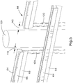
- Fig. 5 illustrates a section of the aisle containment frame 58 positioned around the building column 100.
- the frame 58 includes mid span posts 120 that are located at each side of the building column 100.
- Each mid span post 120 is designed to support the wall beam 64 and attached wall beam clamp 66 with a flap seal 68.
- the width of the gap 110 varies depending on the column size, shape and location within the aisle containment system.
- the containment column adapter 150 of the present invention is designed to seal the gap 110 between the cabinet 50 and the wall beam 64 and the building column 100.
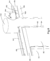
- Fig. 6 illustrates an installed containment column adapter 150 closing and sealing the gap 110 between the building column 100 and the wall beams 64.
- Fig. 7 illustrates an exploded view of the containment column adapter 150.
- the containment column adapter 150 includes a wall beam extension 152 and a wall beam extension clamp 164. These parts are designed to seal the gap 110 between the building column 100 and the wall beam 64.
- the wall beam extension 152 is positioned below the wall beam 64.
- the wall beam extension 152 includes a horizontal member 154 with a plurality of adjustment slots 156 to enable the wall beam extension 152 to be adjusted to the width of the gap 110.
- the wall beam extension 152 also includes a vertical member 158 with adjustment slots 160.
- a mid span post 120 is positioned below the wall beam extension 152 and the wall beam 64.
- post studs 122 extending from the mid span post 120 extend through the slots 156 in the wall beam extension 152 into the holes 65 in the bottom surface of the wall beam 64.
- An adhesive foam seal 172 is attached to the end face 162 of the wall beam extension 152. The foam seal 172 can be compressed against the building column 100 to provide a seal.
- a wall beam extension clamp 164 with a flap seal 168 attached thereto is secured to the wall beam extension 152.
- the wall beam extension clamp 164 includes adjustment slots 166.
- the wall beam extension clamp 164 is placed behind the wall beam clamp 66.
- the wall beam extension clamp 164 is held in place by the wall beam extension clamp attachment screw 170 and the last wall beam clamp attachment screw 67.
- the flap seal 168 provides a seal against a cabinet or blanking panel, similar to the flap seal 68 that is provided with the wall beam 64.
- a ceiling mounted threaded rod (not illustrated) can be used instead of the mid span post to support the wall beam and wall beam extensions.
- the threaded rods would pass through the holes in the wall beam into the slots in the wall beam extension.
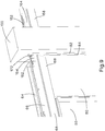
- Figs. 8 and 9 illustrate a perspective view of a section of the aisle containment system with an installed containment column adapter 150, cabinets 50, and vertical blanking panels 80 with vertical stiffeners 82 to seal the gaps 110 between the building column 100 and the cabinets 50.
- Fig. 8 illustrates the containment column adapter 150 installed around a cylindrical building column
- Fig. 9 illustrates the containment column adapter installed around a rectangular building column.
- the blanking panels 80 and vertical stiffener 82 are disclosed in Applicant's U.S. Patent No. 9,255,417 .
- the blanking panel 80 is positioned adjacent the cabinet 50 and in front of the mid span post 120.
- the blanking panel 80 is also positioned behind the wall beam clamp 66 and the wall beam extension clamp 164.
- the flap seal 168 presses against the blanking panel 80 to create a seal.
- the blanking panel 80 covers the area below the wall beam 64 and between the cabinet 50 and the building column 100. If necessary, the width of the vertical blanking panel 80 is adjusted to fill the gap 110 between the building column 100 and the cabinet 50. The blanking panel 80 butts up against the building column 100. If desired, foam strips can also be used to provide an additional seal between the blanking panel 80 and the building column 100.
- the aisle beams 86 and ceiling panels 90 also need to accommodate each building column 100.
- the ceiling panels 90 need to be cut to fit around the cylindrical or rectangular building column. If an aisle beam 86 is going to interfere with the building column 100, the aisle beam 86 must also be cut around the building column 100. Without a wall beam 64, there is nothing supporting the end of the aisle beam 86. As a result, a flexible roof support 190 and aisle beam supports 200 must be installed to support the aisle beam 86 and ceiling panels 90.
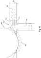
- Figs. 10-15 illustrate the containment column adapter 150, the flexible roof support 190 with the adjusted aisle beams 86 and ceiling panels 90.
- Fig. 10 illustrates an aisle beam 86 located between the wall beam 64 and the building column 100.
- a flexible roof support 190 is installed around the building column 100 to support the end of the aisle beam 86 next to the building column 100.
- the flexible roof support 190 conforms to the structure of the building column 100, cylindrical or rectangular, respectively.
- the flexible roof support 190 is secured to the building column 100 prior to installing the aisle beams 86 and ceiling panels 90.
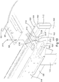
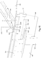
- Figs. 13-15 provide detailed views of the aisle beam 86 being secured to the wall beam extension 152.
- the aisle beam 86 is secured to the wall beam extension 152 via aisle beam supports 200 and fastening devices 212, 214.
- the aisle beam supports 200 include a first upwardly extending vertical member 202, a main horizontal member 204, and a second downwardly extending vertical member 208.
- the horizontal main member 204 includes a plurality of holes 206 for receiving fasteners 212.
- the downwardly extending vertical member 208 includes a post 210.
- the aisle beam supports 200 are positioned adjacent to the wall beam extension 152 with the posts 210 extending through the top slot 160 in the wall beam extension 152. Nuts 214 engage the posts 210 to secure the aisle beam supports 200 to the wall beam extension 152 (see Fig. 14 ).
- the aisle beam 86 is positioned on the aisle beam supports 200 and a fastener 212 is inserted through openings 88, 206 in the aisle beam and the aisle beam supports, respectively, (see Fig. 15 ). Additionally, if desired, only one aisle beam support 200 can be used when only half of the aisle beam 86 is supported by the wall beam 64.
- Figs. 13-15 also illustrate the ceiling panels 90 cut to fit around the circular building column 100.
- Foam strips can be installed, where necessary, to seal any remaining gaps created when cutting ceiling panels and the aisle beams around the building column. Blanking foam strips may also be used to seal across any exposed slots, such as on the vertical face of the wall beam extension.
Abstract
Description
- This application claims priority to
U.S. Provisional Application No. 62/432,222, filed December 9, 2016 - The present invention relates to an aisle containment system, and more particularly to an aisle containment system installed around a building column.
- Applicant's
U.S. Patent No. 9,255,417 - A problem occurs when the independent aisle containment system is to be installed in an area with pre-existing building columns. Building columns are commonly found in data center environments, particularly larger data centers. To effectively utilize the space within a data center and increase efficiency of the cooling systems, it is desirable to install an aisle containment system around the building columns, while maintaining separation of the hot and cold air within the data center.
- Thus, it would be desirable to provide a device to seal the gaps around the pre-existing building columns thereby enabling the independent aisle containment system to be installed around the building column while maintaining containment of the aisle.
- An aisle containment system is disclosed. The aisle containment system includes a frame defined by wall beams, header frames, and a plurality of posts. A plurality of cabinets are positioned within the frame. Mid-span posts are positioned adjacent pre-existing building columns that are located within the frame. The mid-span posts support the wall beams on one side of the frame. At least one containment column adapter is secured to one of the wall beams and one of the mid-span posts. The at least one containment column adapter is installed to seal the gap between the building column and the wall beam within the frame of the aisle containment system.
- The aisle containment system is further disclosed in the following numbered clauses:
- 1. An aisle containment system comprising:
- a frame defined by wall beams, header frames, and a plurality of posts;
- a plurality of cabinets positioned within the frame;
- mid-span posts positioned adjacent building columns located within the frame, the mid-span posts for supporting the wall beams on one side of the frame;
- at least one containment column adapter secured to one of the wall beams and one of the mid-span posts; wherein the at least one containment column adapter seals gaps between the building column and the wall beam within the frame of the aisle containment system.
- 2. The aisle containment system of
clause 1, wherein the at least one containment column adapter includes a wall beam extension and a wall beam extension clamp, wherein the wall beam extension is positioned below one of the wall beams. - 3. The aisle containment system of any preceding clause, wherein the wall beam extension includes a horizontal member with a plurality of slots for enabling the wall beam extension to be adjusted to fill a width of the gap.
- 4. The aisle containment system of any preceding clause, wherein post studs extend from the mid-span posts, the post studs extend through the slots in the horizontal member of the wall beam extension and into holes in a bottom surface of one of the wall beams.
- 5. The aisle containment system of any preceding clause , wherein the wall beam extension includes a vertical member with a plurality of slots for receiving fasteners to secure the wall beam extension clamp.
- 6. The aisle containment system of any preceding clause, wherein the wall beam extension clamp having a flap seal and adjustment slots for receiving fasteners to secure the wall beam extension clamp.
- 7. The aisle containment system of any preceding clause, wherein the wall beam extension having an end face; a foam seal is attached to the end face for providing a seal between the wall beam extension and the building column.
- 8. The aisle containment system of any preceding clause, further comprising a plurality of blanking panels positioned within the frame for filling openings within the aisle containment system.
- 9. The aisle containment system of any preceding clause, further comprising ceiling panels and aisle beams extending across a width of the frame; and
a flexible roof support secured to the building column, the flexible roof support receives an end of the aisle beams adjacent the building column. - 10. The aisle containment system of any preceding clause, wherein the flexible roof support conforms to the structure of the building column.
- 11. The aisle containment system of any preceding clause, further comprising aisle beam supports, the aisle beam supports secure one of the aisle beams to the wall beam extension.
- 12. The aisle containment system of any preceding clause, wherein the aisle beam supports include a first upwardly extending vertical member, a main horizontal member, and a second downwardly extending member.
- 13. The aisle containment system of any preceding clause, wherein the downwardly extending vertical member includes a post that extends through one of the slots in the wall beam extension; and the horizontal main member includes a plurality of holes for receiving fasteners to secure one of the aisle beams to the aisle beam supports.
-
-
Fig. 1 is a perspective view of cabinets and a cylindrical building column in a data center. -
Fig. 2 is a perspective view of an aisle containment system installed around the cylindrical building column ofFig. 1 . -
Fig. 3 is a left top perspective view of the aisle containment system of the present invention with cabinets, ceiling panels, and a sliding door installed. -
Fig. 4 is a right top perspective view of the aisle containment system ofFig. 3 . -
Fig. 5 is a perspective view of the wall beams of the aisle containment system and the building column ofFig. 2 . -
Fig. 6 is a perspective view of the wall beams and the building column ofFig. 2 with the containment column adapter of the present invention. -
Fig. 7 is an exploded perspective view of the containment column adapter ofFig. 6 . -
Fig. 8 is a perspective view of the aisle containment system ofFig. 6 with cabinets and blanking panels installed around the cylindrical building column. -
Fig. 9 is a perspective view of the aisle containment system ofFig. 6 with cabinets and blanking panels installed around a rectangular building column. -
Fig. 10 is a top view of the ceiling panels and aisle beam around the building column of the aisle containment system ofFig. 4 . -
Fig. 11 is a perspective view from inside the aisle of the cylindrical building column with the flexible roof support ofFig. 10 . -
Fig. 12 is a perspective view from inside the aisle of the rectangular building column with the flexible roof support ofFig. 10 . -
Fig. 13 is a partial exploded top perspective view of the aisle beam and aisle beam supports ofFig. 10 . -
Fig. 14 is a partially assembled view of the wall beam extension and the aisle beam supports ofFig. 13 . -
Fig. 15 is a partially assembled top perspective view of the wall beam extension, the aisle beam supports and the aisle beam ofFig. 13 . -
Fig. 1 illustrates a plurality ofcabinets 50 installed in a data center around apre-existing building column 100. Thecabinets 50 are arranged in two rows forming anaisle 54 therebetween. Often thepre-existing building columns 100 interfere with the formation of the aisle containment system. Thebuilding columns 100 are generally cylindrical or rectangular. As illustrated inFig. 1 , the row formed around thebuilding column 100 includesgaps 110 or openings between thebuilding column 100 andadjacent cabinets 50. The present invention provides acontainment column adapter 150 that closes thegap 110 between thebuilding column 100 and thecabinets 50 thereby maintaining containment of theaisle 54 formed by thecabinets 50. -
Fig. 2 illustrates an aisle containment system installed around a cylindrical building column. Thecabinets 50 have been removed from one side of the aisle to illustrate theframe 58 forming the aisle and positioned around thebuilding column 100. Theframe 58 is similar to the frame of Applicant's aisle containment system disclosed inU.S. Patent No. 9,255,417 frame 58 is positioned on thefloor 56. Although only one end is illustrated, posts 60 and aheader frame 62 are located at each end of theframe 58. Wall beams 64 are positioned above thecabinets 50 and are designed to extend between theposts 60. - The
frame 58 includes twomid span posts 120 that are positioned on each side of thebuilding column 100. Themid span posts 120 support the wall beams 64 on one side of theframe 58. -
Figs. 3 and4 illustrate theaisle containment frame 58 ofFig. 2 withadditional cabinets 50, blankingpanels 80, and a slidingdoor 96 installed to form an aisle containment system.Figs. 3 and4 also illustrate a plurality of aisle beams 86 andceiling panels 90 installed over theaisle 54. The aisle beams 86 andceiling panels 90 extend between the wall beams 64 of theframe 58.Figs. 3 and4 also illustrate thecontainment column adapter 150 installed around thebuilding column 100 and the aislecontainment system frame 58. -
Figs. 5-15 illustrate thebuilding column 100 and thecontainment column adapter 150 of the present invention filling thegaps 110 between thebuilding column 100 and the aisle containment system. Thecabinets 50 have been removed in several of the figures to more clearly illustrate theaisle containment frame 58 andcontainment column adapter 150. -
Fig. 5 illustrates a section of theaisle containment frame 58 positioned around thebuilding column 100. As illustrated inFig. 2 , theframe 58 includesmid span posts 120 that are located at each side of thebuilding column 100. Eachmid span post 120 is designed to support thewall beam 64 and attachedwall beam clamp 66 with aflap seal 68. There is agap 110 between thebuilding column 100 and thewall beam 64 and eachmid span post 120. Thisgap 110 must be blocked to maintain containment of the hot or cold air in the aisle. The width of thegap 110 varies depending on the column size, shape and location within the aisle containment system. - The
containment column adapter 150 of the present invention is designed to seal thegap 110 between thecabinet 50 and thewall beam 64 and thebuilding column 100.Fig. 6 illustrates an installedcontainment column adapter 150 closing and sealing thegap 110 between thebuilding column 100 and the wall beams 64. -
Fig. 7 illustrates an exploded view of thecontainment column adapter 150. Thecontainment column adapter 150 includes awall beam extension 152 and a wallbeam extension clamp 164. These parts are designed to seal thegap 110 between thebuilding column 100 and thewall beam 64. Thewall beam extension 152 is positioned below thewall beam 64. Thewall beam extension 152 includes ahorizontal member 154 with a plurality ofadjustment slots 156 to enable thewall beam extension 152 to be adjusted to the width of thegap 110. Thewall beam extension 152 also includes avertical member 158 withadjustment slots 160. Amid span post 120 is positioned below thewall beam extension 152 and thewall beam 64. As illustrated by dashed lines, poststuds 122 extending from themid span post 120 extend through theslots 156 in thewall beam extension 152 into theholes 65 in the bottom surface of thewall beam 64. Anadhesive foam seal 172 is attached to theend face 162 of thewall beam extension 152. Thefoam seal 172 can be compressed against thebuilding column 100 to provide a seal. - A wall
beam extension clamp 164 with aflap seal 168 attached thereto is secured to thewall beam extension 152. The wallbeam extension clamp 164 includesadjustment slots 166. The wallbeam extension clamp 164 is placed behind thewall beam clamp 66. The wallbeam extension clamp 164 is held in place by the wall beam extensionclamp attachment screw 170 and the last wall beamclamp attachment screw 67. Theflap seal 168 provides a seal against a cabinet or blanking panel, similar to theflap seal 68 that is provided with thewall beam 64. - Alternatively, a ceiling mounted threaded rod (not illustrated) can be used instead of the mid span post to support the wall beam and wall beam extensions. The threaded rods would pass through the holes in the wall beam into the slots in the wall beam extension.
-
Figs. 8 and9 illustrate a perspective view of a section of the aisle containment system with an installedcontainment column adapter 150,cabinets 50, andvertical blanking panels 80 withvertical stiffeners 82 to seal thegaps 110 between thebuilding column 100 and thecabinets 50.Fig. 8 illustrates thecontainment column adapter 150 installed around a cylindrical building column andFig. 9 illustrates the containment column adapter installed around a rectangular building column. The blankingpanels 80 andvertical stiffener 82 are disclosed in Applicant'sU.S. Patent No. 9,255,417 panel 80 is positioned adjacent thecabinet 50 and in front of themid span post 120. The blankingpanel 80 is also positioned behind thewall beam clamp 66 and the wallbeam extension clamp 164. Theflap seal 168 presses against the blankingpanel 80 to create a seal. - The blanking
panel 80 covers the area below thewall beam 64 and between thecabinet 50 and thebuilding column 100. If necessary, the width of thevertical blanking panel 80 is adjusted to fill thegap 110 between thebuilding column 100 and thecabinet 50. The blankingpanel 80 butts up against thebuilding column 100. If desired, foam strips can also be used to provide an additional seal between the blankingpanel 80 and thebuilding column 100. - As illustrated in
Figs. 3 and4 , the aisle beams 86 andceiling panels 90 also need to accommodate eachbuilding column 100. Theceiling panels 90 need to be cut to fit around the cylindrical or rectangular building column. If anaisle beam 86 is going to interfere with thebuilding column 100, theaisle beam 86 must also be cut around thebuilding column 100. Without awall beam 64, there is nothing supporting the end of theaisle beam 86. As a result, aflexible roof support 190 and aisle beam supports 200 must be installed to support theaisle beam 86 andceiling panels 90. -
Figs. 10-15 illustrate thecontainment column adapter 150, theflexible roof support 190 with the adjusted aisle beams 86 andceiling panels 90.Fig. 10 illustrates anaisle beam 86 located between thewall beam 64 and thebuilding column 100. Aflexible roof support 190 is installed around thebuilding column 100 to support the end of theaisle beam 86 next to thebuilding column 100. As illustrated inFigs. 11 and12 , theflexible roof support 190 conforms to the structure of thebuilding column 100, cylindrical or rectangular, respectively. Theflexible roof support 190 is secured to thebuilding column 100 prior to installing the aisle beams 86 andceiling panels 90. -
Figs. 13-15 provide detailed views of theaisle beam 86 being secured to thewall beam extension 152. Theaisle beam 86 is secured to thewall beam extension 152 via aisle beam supports 200 andfastening devices - The aisle beam supports 200 include a first upwardly extending
vertical member 202, a mainhorizontal member 204, and a second downwardly extendingvertical member 208. The horizontalmain member 204 includes a plurality ofholes 206 for receivingfasteners 212. The downwardly extendingvertical member 208 includes apost 210. The aisle beam supports 200 are positioned adjacent to thewall beam extension 152 with theposts 210 extending through thetop slot 160 in thewall beam extension 152.Nuts 214 engage theposts 210 to secure the aisle beam supports 200 to the wall beam extension 152 (seeFig. 14 ). Once the aisle beam supports 200 are secured to thewall beam extension 152, theaisle beam 86 is positioned on the aisle beam supports 200 and afastener 212 is inserted throughopenings Fig. 15 ). Additionally, if desired, only oneaisle beam support 200 can be used when only half of theaisle beam 86 is supported by thewall beam 64. -
Figs. 13-15 also illustrate theceiling panels 90 cut to fit around thecircular building column 100. - Foam strips can be installed, where necessary, to seal any remaining gaps created when cutting ceiling panels and the aisle beams around the building column. Blanking foam strips may also be used to seal across any exposed slots, such as on the vertical face of the wall beam extension.
- Furthermore, while the preferred embodiments of the present invention have been shown and described, it will be obvious to those skilled in the art that changes and modifications may be made without departing from the teaching of the invention. The matter set forth in the foregoing description and accompanying drawings is offered by way of illustration only and not as limitation.
Claims (13)
- An aisle containment system comprising:a frame defined by wall beams, header frames, and a plurality of posts;a plurality of cabinets positioned within the frame;mid-span posts positioned adjacent building columns located within the frame, the mid-span posts for supporting the wall beams on one side of the frame;at least one containment column adapter secured to one of the wall beams and one of the mid-span posts; wherein the at least one containment column adapter seals gaps between the building column and the wall beam within the frame of the aisle containment system.
- The aisle containment system of claim 1, wherein the at least one containment column adapter includes a wall beam extension and a wall beam extension clamp, wherein the wall beam extension is positioned below one of the wall beams.
- The aisle containment system of claim 2, wherein the wall beam extension includes a horizontal member with a plurality of slots for enabling the wall beam extension to be adjusted to fill a width of the gap.
- The aisle containment system of claim 3, wherein post studs extend from the mid-span posts, the post studs extend through the slots in the horizontal member of the wall beam extension and into holes in a bottom surface of one of the wall beams.
- The aisle containment system of claim 2, wherein the wall beam extension includes a vertical member with a plurality of slots for receiving fasteners to secure the wall beam extension clamp.
- The aisle containment system of claim 2, wherein the wall beam extension clamp having a flap seal and adjustment slots for receiving fasteners to secure the wall beam extension clamp.
- The aisle containment system of claim 2, wherein the wall beam extension having an end face; a foam seal is attached to the end face for providing a seal between the wall beam extension and the building column.
- The aisle containment system of any preceding claim, further comprising a plurality of blanking panels positioned within the frame for filling openings within the aisle containment system.
- The aisle containment system of any preceding claim, further comprising ceiling panels and aisle beams extending across a width of the frame; anda flexible roof support secured to the building column, the flexible roof support receives an end of the aisle beams adjacent the building column.
- The aisle containment system of claim 9, wherein the flexible roof support conforms to the structure of the building column.
- The aisle containment system of claim 9, further comprising aisle beam supports, the aisle beam supports secure one of the aisle beams to the wall beam extension.
- The aisle containment system of claim 11, wherein the aisle beam supports include a first upwardly extending vertical member, a main horizontal member, and a second downwardly extending vertical member.
- The aisle containment system of claim 12, wherein the downwardly extending vertical member includes a post that extends through one of the slots in the wall beam extension; and the horizontal main member includes a plurality of holes for receiving fasteners to secure one of the aisle beams to the aisle beam supports.
Applications Claiming Priority (2)
| Application Number | Priority Date | Filing Date | Title |
|---|---|---|---|
| US201662432222P | 2016-12-09 | 2016-12-09 | |
| US15/832,902 US10206303B2 (en) | 2016-12-09 | 2017-12-06 | Universal aisle containment column adapter |
Publications (2)
| Publication Number | Publication Date |
|---|---|
| EP3334262A1 true EP3334262A1 (en) | 2018-06-13 |
| EP3334262B1 EP3334262B1 (en) | 2020-09-09 |
Family
ID=60661789
Family Applications (1)
| Application Number | Title | Priority Date | Filing Date |
|---|---|---|---|
| EP17206126.9A Active EP3334262B1 (en) | 2016-12-09 | 2017-12-08 | Universal aisle containment column adapter |
Country Status (2)
| Country | Link |
|---|---|
| US (1) | US10206303B2 (en) |
| EP (1) | EP3334262B1 (en) |
Families Citing this family (4)
| Publication number | Priority date | Publication date | Assignee | Title |
|---|---|---|---|---|
| US10492326B2 (en) * | 2018-02-16 | 2019-11-26 | Eaton Intelligent Power Limited | Aisle containment system for data center |
| US10255729B1 (en) * | 2018-05-29 | 2019-04-09 | Exploring, Inc. | System and method for haptic mapping of a configurable virtual reality environment |
| CN213847233U (en) * | 2020-12-07 | 2021-07-30 | 维谛公司 | Heavy-load anti-seismic cabinet frame |
| US20230209760A1 (en) * | 2021-12-23 | 2023-06-29 | Baidu Usa Llc | Containment system for electronics racks |
Citations (4)
| Publication number | Priority date | Publication date | Assignee | Title |
|---|---|---|---|---|
| JP2011257075A (en) * | 2010-06-09 | 2011-12-22 | Ntt Facilities Inc | Inter-rack shielding structure, and air conditioning system for computer room |
| US20140196394A1 (en) * | 2013-01-11 | 2014-07-17 | Chatsworth Products, Inc. | Modular thermal isolation barrier for data processing equipment structure |
| WO2015138866A1 (en) * | 2014-03-13 | 2015-09-17 | Upsite Technologies, Inc. | Adjustable airflow barrier system |
| US9255417B2 (en) | 2014-03-12 | 2016-02-09 | Panduit Corp. | Independent aisle containment system |
Family Cites Families (29)
| Publication number | Priority date | Publication date | Assignee | Title |
|---|---|---|---|---|
| US2766861A (en) | 1952-06-05 | 1956-10-16 | Abramson Harry | Building wall sidings |
| US5969292A (en) | 1997-11-07 | 1999-10-19 | Ericsson, Inc. | Overhead cabling system for telecommunication switching center |
| GB0207382D0 (en) | 2002-03-28 | 2002-05-08 | Holland Heating Uk Ltd | Computer cabinet |
| US7046514B2 (en) * | 2003-03-19 | 2006-05-16 | American Power Conversion Corporation | Data center cooling |
| US7033267B2 (en) | 2003-05-13 | 2006-04-25 | American Power Conversion Corporation | Rack enclosure |
| US7293666B2 (en) | 2004-11-17 | 2007-11-13 | American Power Conversion Corporation | Equipment enclosure kit and assembly method |
| US7841199B2 (en) * | 2005-05-17 | 2010-11-30 | American Power Conversion Corporation | Cold aisle isolation |
| US8425287B2 (en) * | 2007-01-23 | 2013-04-23 | Schneider Electric It Corporation | In-row air containment and cooling system and method |
| US7764495B2 (en) | 2007-04-30 | 2010-07-27 | Adc Telecommunications, Inc. | Telecommunication cabinet with airflow ducting |
| US7477514B2 (en) | 2007-05-04 | 2009-01-13 | International Business Machines Corporation | Method of facilitating cooling of electronics racks of a data center employing multiple cooling stations |
| US8072780B1 (en) * | 2007-06-14 | 2011-12-06 | Switch Communications Group LLC | Integrated wiring system and thermal shield support apparatus for a data center |
| US8180495B1 (en) * | 2007-06-14 | 2012-05-15 | Switch Communications Group LLC | Air handling control system for a data center |
| US7656660B2 (en) | 2007-11-20 | 2010-02-02 | International Business Machines Corporation | Airflow arresting apparatus and method for facilitating cooling of an electronics rack of a data center |
| US8037644B2 (en) | 2008-01-07 | 2011-10-18 | International Business Machines Corporation | Fire-code-compatible, collapsible partitions to prevent unwanted airflow between computer-room cold aisles and hot aisles |
| DE102008024973B3 (en) | 2008-05-23 | 2009-09-03 | Knürr AG | Housing and installation method for a warm aisle of a computer room |
| US20100024353A1 (en) * | 2008-07-29 | 2010-02-04 | Green Horizon Manufacturing Llc | Method for deploying prefabricated structures arranged in a complementary layout |
| US9066450B2 (en) * | 2008-10-24 | 2015-06-23 | Wright Line, Llc | Data center air routing system |
| US20100248609A1 (en) * | 2009-03-24 | 2010-09-30 | Wright Line, Llc | Assembly For Providing A Downflow Return Air Supply |
| US8701737B2 (en) * | 2009-11-09 | 2014-04-22 | LDM Products, Inc | Retractable computer rack aisle roof |
| WO2011140463A1 (en) * | 2010-05-06 | 2011-11-10 | Eaton Corporation | Aisle enclosure system |
| US8628153B2 (en) | 2010-05-13 | 2014-01-14 | Pandult Corp. | Aisle containment system |
| US8628158B2 (en) | 2010-05-13 | 2014-01-14 | Panduit Corp. | Aisle containment system |
| US8787023B2 (en) | 2010-09-10 | 2014-07-22 | Chatsworth Products, Inc. | Rail mounting clamp for electronic equipment enclosure |
| US9313927B2 (en) | 2010-11-08 | 2016-04-12 | Chatsworth Products, Inc. | Header panel assembly for preventing air circulation above electronic equipment enclosure |
| US9560777B2 (en) * | 2010-11-08 | 2017-01-31 | Chatsworth Products, Inc. | Door closer mechanism for hot/cold aisle air containment room |
| US9585266B2 (en) | 2010-11-08 | 2017-02-28 | Chatsworth Products, Inc. | Header panel assembly for preventing air circulation above electronic equipment enclosure |
| US9955616B2 (en) | 2010-11-08 | 2018-04-24 | Chatsworth Products, Inc. | Header panel assembly for preventing air circulation above electronic equipment enclosure |
| US8857120B2 (en) * | 2012-04-19 | 2014-10-14 | Panduit Corp. | Ceiling supported cold aisle containment system |
| US8713869B1 (en) | 2013-03-15 | 2014-05-06 | Gordon Sales, Inc. | Suspended containment wall system |
-
2017
- 2017-12-06 US US15/832,902 patent/US10206303B2/en active Active
- 2017-12-08 EP EP17206126.9A patent/EP3334262B1/en active Active
Patent Citations (4)
| Publication number | Priority date | Publication date | Assignee | Title |
|---|---|---|---|---|
| JP2011257075A (en) * | 2010-06-09 | 2011-12-22 | Ntt Facilities Inc | Inter-rack shielding structure, and air conditioning system for computer room |
| US20140196394A1 (en) * | 2013-01-11 | 2014-07-17 | Chatsworth Products, Inc. | Modular thermal isolation barrier for data processing equipment structure |
| US9255417B2 (en) | 2014-03-12 | 2016-02-09 | Panduit Corp. | Independent aisle containment system |
| WO2015138866A1 (en) * | 2014-03-13 | 2015-09-17 | Upsite Technologies, Inc. | Adjustable airflow barrier system |
Also Published As
| Publication number | Publication date |
|---|---|
| US10206303B2 (en) | 2019-02-12 |
| US20180168064A1 (en) | 2018-06-14 |
| EP3334262B1 (en) | 2020-09-09 |
Similar Documents
| Publication | Publication Date | Title |
|---|---|---|
| US9883607B2 (en) | Independent aisle containment system | |
| US10206303B2 (en) | Universal aisle containment column adapter | |
| US5347775A (en) | Hurricane shutters for windows | |
| US20220018523A1 (en) | Bar hanger assembly with crossmembers and housing assemblies using same | |
| US20170292266A1 (en) | Modular walling systems | |
| US8266854B2 (en) | Grommet closure device | |
| US20110173906A1 (en) | Floor gland | |
| CN109155119B (en) | Display device | |
| US20180132385A1 (en) | Containment Systems and Related Methods of Use | |
| US20160017605A1 (en) | Wall panel connecting system for modular building units | |
| US3436886A (en) | Frame mounting in wall panel system | |
| MX2013010272A (en) | Wall insulation system with blocks having angled sides. | |
| CN108867979B (en) | Ceiling cuts off integrative system | |
| US5644477A (en) | Frame carrier and modular cover panel system | |
| KR20120074097A (en) | Hanger with varialbe binding site and ceiling support system that is applied | |
| US10358822B2 (en) | Integrated cross bar with mounting tab for grille | |
| JP5657153B1 (en) | Air-conditioning mechanism for racks for heating equipment | |
| EP1882791A2 (en) | Modular panel for creating ventilated facades of building | |
| JP2006077542A (en) | Partition and panel element mounting structure | |
| JP2007170177A (en) | Partitioning fitting | |
| EP2322868A2 (en) | Housing for HVAC apparatus | |
| JP3879826B2 (en) | Frame furniture | |
| JP4310538B2 (en) | Face-to-face kitchen unit and its construction method | |
| JP6816881B2 (en) | Handrail structure and its mounting method | |
| CN107327057B (en) | Curtain wall back plate structure and curtain wall building ceiling structure |
Legal Events
| Date | Code | Title | Description |
|---|---|---|---|
| PUAI | Public reference made under article 153(3) epc to a published international application that has entered the european phase |
Free format text: ORIGINAL CODE: 0009012 |
|
| STAA | Information on the status of an ep patent application or granted ep patent |
Free format text: STATUS: THE APPLICATION HAS BEEN PUBLISHED |
|
| AK | Designated contracting states |
Kind code of ref document: A1 Designated state(s): AL AT BE BG CH CY CZ DE DK EE ES FI FR GB GR HR HU IE IS IT LI LT LU LV MC MK MT NL NO PL PT RO RS SE SI SK SM TR |
|
| AX | Request for extension of the european patent |
Extension state: BA ME |
|
| STAA | Information on the status of an ep patent application or granted ep patent |
Free format text: STATUS: REQUEST FOR EXAMINATION WAS MADE |
|
| 17P | Request for examination filed |
Effective date: 20181127 |
|
| RBV | Designated contracting states (corrected) |
Designated state(s): AL AT BE BG CH CY CZ DE DK EE ES FI FR GB GR HR HU IE IS IT LI LT LU LV MC MK MT NL NO PL PT RO RS SE SI SK SM TR |
|
| GRAP | Despatch of communication of intention to grant a patent |
Free format text: ORIGINAL CODE: EPIDOSNIGR1 |
|
| STAA | Information on the status of an ep patent application or granted ep patent |
Free format text: STATUS: GRANT OF PATENT IS INTENDED |
|
| INTG | Intention to grant announced |
Effective date: 20200409 |
|
| GRAS | Grant fee paid |
Free format text: ORIGINAL CODE: EPIDOSNIGR3 |
|
| GRAA | (expected) grant |
Free format text: ORIGINAL CODE: 0009210 |
|
| STAA | Information on the status of an ep patent application or granted ep patent |
Free format text: STATUS: THE PATENT HAS BEEN GRANTED |
|
| AK | Designated contracting states |
Kind code of ref document: B1 Designated state(s): AL AT BE BG CH CY CZ DE DK EE ES FI FR GB GR HR HU IE IS IT LI LT LU LV MC MK MT NL NO PL PT RO RS SE SI SK SM TR |
|
| REG | Reference to a national code |
Ref country code: GB Ref legal event code: FG4D |
|
| REG | Reference to a national code |
Ref country code: AT Ref legal event code: REF Ref document number: 1313236 Country of ref document: AT Kind code of ref document: T Effective date: 20200915 Ref country code: CH Ref legal event code: EP |
|
| REG | Reference to a national code |
Ref country code: IE Ref legal event code: FG4D |
|
| REG | Reference to a national code |
Ref country code: DE Ref legal event code: R096 Ref document number: 602017023221 Country of ref document: DE |
|
| REG | Reference to a national code |
Ref country code: LT Ref legal event code: MG4D |
|
| PG25 | Lapsed in a contracting state [announced via postgrant information from national office to epo] |
Ref country code: FI Free format text: LAPSE BECAUSE OF FAILURE TO SUBMIT A TRANSLATION OF THE DESCRIPTION OR TO PAY THE FEE WITHIN THE PRESCRIBED TIME-LIMIT Effective date: 20200909 Ref country code: SE Free format text: LAPSE BECAUSE OF FAILURE TO SUBMIT A TRANSLATION OF THE DESCRIPTION OR TO PAY THE FEE WITHIN THE PRESCRIBED TIME-LIMIT Effective date: 20200909 Ref country code: HR Free format text: LAPSE BECAUSE OF FAILURE TO SUBMIT A TRANSLATION OF THE DESCRIPTION OR TO PAY THE FEE WITHIN THE PRESCRIBED TIME-LIMIT Effective date: 20200909 Ref country code: GR Free format text: LAPSE BECAUSE OF FAILURE TO SUBMIT A TRANSLATION OF THE DESCRIPTION OR TO PAY THE FEE WITHIN THE PRESCRIBED TIME-LIMIT Effective date: 20201210 Ref country code: LT Free format text: LAPSE BECAUSE OF FAILURE TO SUBMIT A TRANSLATION OF THE DESCRIPTION OR TO PAY THE FEE WITHIN THE PRESCRIBED TIME-LIMIT Effective date: 20200909 Ref country code: BG Free format text: LAPSE BECAUSE OF FAILURE TO SUBMIT A TRANSLATION OF THE DESCRIPTION OR TO PAY THE FEE WITHIN THE PRESCRIBED TIME-LIMIT Effective date: 20201209 Ref country code: NO Free format text: LAPSE BECAUSE OF FAILURE TO SUBMIT A TRANSLATION OF THE DESCRIPTION OR TO PAY THE FEE WITHIN THE PRESCRIBED TIME-LIMIT Effective date: 20201209 |
|
| REG | Reference to a national code |
Ref country code: AT Ref legal event code: MK05 Ref document number: 1313236 Country of ref document: AT Kind code of ref document: T Effective date: 20200909 |
|
| REG | Reference to a national code |
Ref country code: NL Ref legal event code: MP Effective date: 20200909 |
|
| PG25 | Lapsed in a contracting state [announced via postgrant information from national office to epo] |
Ref country code: PL Free format text: LAPSE BECAUSE OF FAILURE TO SUBMIT A TRANSLATION OF THE DESCRIPTION OR TO PAY THE FEE WITHIN THE PRESCRIBED TIME-LIMIT Effective date: 20200909 Ref country code: RS Free format text: LAPSE BECAUSE OF FAILURE TO SUBMIT A TRANSLATION OF THE DESCRIPTION OR TO PAY THE FEE WITHIN THE PRESCRIBED TIME-LIMIT Effective date: 20200909 Ref country code: LV Free format text: LAPSE BECAUSE OF FAILURE TO SUBMIT A TRANSLATION OF THE DESCRIPTION OR TO PAY THE FEE WITHIN THE PRESCRIBED TIME-LIMIT Effective date: 20200909 |
|
| PG25 | Lapsed in a contracting state [announced via postgrant information from national office to epo] |
Ref country code: RO Free format text: LAPSE BECAUSE OF FAILURE TO SUBMIT A TRANSLATION OF THE DESCRIPTION OR TO PAY THE FEE WITHIN THE PRESCRIBED TIME-LIMIT Effective date: 20200909 Ref country code: PT Free format text: LAPSE BECAUSE OF FAILURE TO SUBMIT A TRANSLATION OF THE DESCRIPTION OR TO PAY THE FEE WITHIN THE PRESCRIBED TIME-LIMIT Effective date: 20210111 Ref country code: CZ Free format text: LAPSE BECAUSE OF FAILURE TO SUBMIT A TRANSLATION OF THE DESCRIPTION OR TO PAY THE FEE WITHIN THE PRESCRIBED TIME-LIMIT Effective date: 20200909 Ref country code: SM Free format text: LAPSE BECAUSE OF FAILURE TO SUBMIT A TRANSLATION OF THE DESCRIPTION OR TO PAY THE FEE WITHIN THE PRESCRIBED TIME-LIMIT Effective date: 20200909 Ref country code: EE Free format text: LAPSE BECAUSE OF FAILURE TO SUBMIT A TRANSLATION OF THE DESCRIPTION OR TO PAY THE FEE WITHIN THE PRESCRIBED TIME-LIMIT Effective date: 20200909 |
|
| PG25 | Lapsed in a contracting state [announced via postgrant information from national office to epo] |
Ref country code: AT Free format text: LAPSE BECAUSE OF FAILURE TO SUBMIT A TRANSLATION OF THE DESCRIPTION OR TO PAY THE FEE WITHIN THE PRESCRIBED TIME-LIMIT Effective date: 20200909 Ref country code: AL Free format text: LAPSE BECAUSE OF FAILURE TO SUBMIT A TRANSLATION OF THE DESCRIPTION OR TO PAY THE FEE WITHIN THE PRESCRIBED TIME-LIMIT Effective date: 20200909 Ref country code: ES Free format text: LAPSE BECAUSE OF FAILURE TO SUBMIT A TRANSLATION OF THE DESCRIPTION OR TO PAY THE FEE WITHIN THE PRESCRIBED TIME-LIMIT Effective date: 20200909 Ref country code: IS Free format text: LAPSE BECAUSE OF FAILURE TO SUBMIT A TRANSLATION OF THE DESCRIPTION OR TO PAY THE FEE WITHIN THE PRESCRIBED TIME-LIMIT Effective date: 20210109 |
|
| REG | Reference to a national code |
Ref country code: DE Ref legal event code: R097 Ref document number: 602017023221 Country of ref document: DE |
|
| PG25 | Lapsed in a contracting state [announced via postgrant information from national office to epo] |
Ref country code: SK Free format text: LAPSE BECAUSE OF FAILURE TO SUBMIT A TRANSLATION OF THE DESCRIPTION OR TO PAY THE FEE WITHIN THE PRESCRIBED TIME-LIMIT Effective date: 20200909 |
|
| PLBE | No opposition filed within time limit |
Free format text: ORIGINAL CODE: 0009261 |
|
| STAA | Information on the status of an ep patent application or granted ep patent |
Free format text: STATUS: NO OPPOSITION FILED WITHIN TIME LIMIT |
|
| REG | Reference to a national code |
Ref country code: CH Ref legal event code: PL |
|
| 26N | No opposition filed |
Effective date: 20210610 |
|
| PG25 | Lapsed in a contracting state [announced via postgrant information from national office to epo] |
Ref country code: SI Free format text: LAPSE BECAUSE OF FAILURE TO SUBMIT A TRANSLATION OF THE DESCRIPTION OR TO PAY THE FEE WITHIN THE PRESCRIBED TIME-LIMIT Effective date: 20200909 Ref country code: DK Free format text: LAPSE BECAUSE OF FAILURE TO SUBMIT A TRANSLATION OF THE DESCRIPTION OR TO PAY THE FEE WITHIN THE PRESCRIBED TIME-LIMIT Effective date: 20200909 Ref country code: MC Free format text: LAPSE BECAUSE OF FAILURE TO SUBMIT A TRANSLATION OF THE DESCRIPTION OR TO PAY THE FEE WITHIN THE PRESCRIBED TIME-LIMIT Effective date: 20200909 |
|
| REG | Reference to a national code |
Ref country code: BE Ref legal event code: MM Effective date: 20201231 |
|
| PG25 | Lapsed in a contracting state [announced via postgrant information from national office to epo] |
Ref country code: IT Free format text: LAPSE BECAUSE OF FAILURE TO SUBMIT A TRANSLATION OF THE DESCRIPTION OR TO PAY THE FEE WITHIN THE PRESCRIBED TIME-LIMIT Effective date: 20200909 Ref country code: LU Free format text: LAPSE BECAUSE OF NON-PAYMENT OF DUE FEES Effective date: 20201208 Ref country code: IE Free format text: LAPSE BECAUSE OF NON-PAYMENT OF DUE FEES Effective date: 20201208 |
|
| PG25 | Lapsed in a contracting state [announced via postgrant information from national office to epo] |
Ref country code: LI Free format text: LAPSE BECAUSE OF NON-PAYMENT OF DUE FEES Effective date: 20201231 Ref country code: CH Free format text: LAPSE BECAUSE OF NON-PAYMENT OF DUE FEES Effective date: 20201231 |
|
| PG25 | Lapsed in a contracting state [announced via postgrant information from national office to epo] |
Ref country code: TR Free format text: LAPSE BECAUSE OF FAILURE TO SUBMIT A TRANSLATION OF THE DESCRIPTION OR TO PAY THE FEE WITHIN THE PRESCRIBED TIME-LIMIT Effective date: 20200909 Ref country code: MT Free format text: LAPSE BECAUSE OF FAILURE TO SUBMIT A TRANSLATION OF THE DESCRIPTION OR TO PAY THE FEE WITHIN THE PRESCRIBED TIME-LIMIT Effective date: 20200909 Ref country code: CY Free format text: LAPSE BECAUSE OF FAILURE TO SUBMIT A TRANSLATION OF THE DESCRIPTION OR TO PAY THE FEE WITHIN THE PRESCRIBED TIME-LIMIT Effective date: 20200909 |
|
| PG25 | Lapsed in a contracting state [announced via postgrant information from national office to epo] |
Ref country code: MK Free format text: LAPSE BECAUSE OF FAILURE TO SUBMIT A TRANSLATION OF THE DESCRIPTION OR TO PAY THE FEE WITHIN THE PRESCRIBED TIME-LIMIT Effective date: 20200909 |
|
| PG25 | Lapsed in a contracting state [announced via postgrant information from national office to epo] |
Ref country code: BE Free format text: LAPSE BECAUSE OF NON-PAYMENT OF DUE FEES Effective date: 20201231 |
|
| PGFP | Annual fee paid to national office [announced via postgrant information from national office to epo] |
Ref country code: DE Payment date: 20221228 Year of fee payment: 6 |
|
| PG25 | Lapsed in a contracting state [announced via postgrant information from national office to epo] |
Ref country code: NL Free format text: LAPSE BECAUSE OF NON-PAYMENT OF DUE FEES Effective date: 20200923 |
|
| PGFP | Annual fee paid to national office [announced via postgrant information from national office to epo] |
Ref country code: GB Payment date: 20231227 Year of fee payment: 7 |
|
| PGFP | Annual fee paid to national office [announced via postgrant information from national office to epo] |
Ref country code: FR Payment date: 20231227 Year of fee payment: 7 |