EP3334060A1 - Accelerated satellite accquisition method by broadening of the field of regard of a reconfigurable phased array antenna. - Google Patents
Accelerated satellite accquisition method by broadening of the field of regard of a reconfigurable phased array antenna. Download PDFInfo
- Publication number
- EP3334060A1 EP3334060A1 EP17197858.8A EP17197858A EP3334060A1 EP 3334060 A1 EP3334060 A1 EP 3334060A1 EP 17197858 A EP17197858 A EP 17197858A EP 3334060 A1 EP3334060 A1 EP 3334060A1
- Authority
- EP
- European Patent Office
- Prior art keywords
- phased array
- array antenna
- antenna
- reconfigurable phased
- regard
- Prior art date
- Legal status (The legal status is an assumption and is not a legal conclusion. Google has not performed a legal analysis and makes no representation as to the accuracy of the status listed.)
- Granted
Links
Images




Classifications
-
- H—ELECTRICITY
- H01—ELECTRIC ELEMENTS
- H01Q—ANTENNAS, i.e. RADIO AERIALS
- H01Q21/00—Antenna arrays or systems
- H01Q21/06—Arrays of individually energised antenna units similarly polarised and spaced apart
- H01Q21/22—Antenna units of the array energised non-uniformly in amplitude or phase, e.g. tapered array or binomial array
-
- H—ELECTRICITY
- H01—ELECTRIC ELEMENTS
- H01Q—ANTENNAS, i.e. RADIO AERIALS
- H01Q1/00—Details of, or arrangements associated with, antennas
- H01Q1/36—Structural form of radiating elements, e.g. cone, spiral, umbrella; Particular materials used therewith
- H01Q1/38—Structural form of radiating elements, e.g. cone, spiral, umbrella; Particular materials used therewith formed by a conductive layer on an insulating support
-
- H—ELECTRICITY
- H04—ELECTRIC COMMUNICATION TECHNIQUE
- H04B—TRANSMISSION
- H04B7/00—Radio transmission systems, i.e. using radiation field
- H04B7/14—Relay systems
- H04B7/15—Active relay systems
- H04B7/185—Space-based or airborne stations; Stations for satellite systems
- H04B7/1851—Systems using a satellite or space-based relay
- H04B7/18517—Transmission equipment in earth stations
-
- G—PHYSICS
- G01—MEASURING; TESTING
- G01S—RADIO DIRECTION-FINDING; RADIO NAVIGATION; DETERMINING DISTANCE OR VELOCITY BY USE OF RADIO WAVES; LOCATING OR PRESENCE-DETECTING BY USE OF THE REFLECTION OR RERADIATION OF RADIO WAVES; ANALOGOUS ARRANGEMENTS USING OTHER WAVES
- G01S19/00—Satellite radio beacon positioning systems; Determining position, velocity or attitude using signals transmitted by such systems
- G01S19/01—Satellite radio beacon positioning systems transmitting time-stamped messages, e.g. GPS [Global Positioning System], GLONASS [Global Orbiting Navigation Satellite System] or GALILEO
- G01S19/13—Receivers
- G01S19/24—Acquisition or tracking or demodulation of signals transmitted by the system
- G01S19/28—Satellite selection
-
- H—ELECTRICITY
- H01—ELECTRIC ELEMENTS
- H01Q—ANTENNAS, i.e. RADIO AERIALS
- H01Q1/00—Details of, or arrangements associated with, antennas
- H01Q1/12—Supports; Mounting means
- H01Q1/14—Supports; Mounting means for wire or other non-rigid radiating elements
- H01Q1/16—Strainers, spreaders, or spacers
-
- H—ELECTRICITY
- H01—ELECTRIC ELEMENTS
- H01Q—ANTENNAS, i.e. RADIO AERIALS
- H01Q1/00—Details of, or arrangements associated with, antennas
- H01Q1/12—Supports; Mounting means
- H01Q1/22—Supports; Mounting means by structural association with other equipment or articles
-
- H—ELECTRICITY
- H01—ELECTRIC ELEMENTS
- H01Q—ANTENNAS, i.e. RADIO AERIALS
- H01Q1/00—Details of, or arrangements associated with, antennas
- H01Q1/50—Structural association of antennas with earthing switches, lead-in devices or lightning protectors
-
- H—ELECTRICITY
- H01—ELECTRIC ELEMENTS
- H01Q—ANTENNAS, i.e. RADIO AERIALS
- H01Q21/00—Antenna arrays or systems
- H01Q21/06—Arrays of individually energised antenna units similarly polarised and spaced apart
- H01Q21/061—Two dimensional planar arrays
- H01Q21/065—Patch antenna array
-
- H—ELECTRICITY
- H01—ELECTRIC ELEMENTS
- H01Q—ANTENNAS, i.e. RADIO AERIALS
- H01Q21/00—Antenna arrays or systems
- H01Q21/06—Arrays of individually energised antenna units similarly polarised and spaced apart
- H01Q21/20—Arrays of individually energised antenna units similarly polarised and spaced apart the units being spaced along or adjacent to a curvilinear path
- H01Q21/205—Arrays of individually energised antenna units similarly polarised and spaced apart the units being spaced along or adjacent to a curvilinear path providing an omnidirectional coverage
-
- H—ELECTRICITY
- H01—ELECTRIC ELEMENTS
- H01Q—ANTENNAS, i.e. RADIO AERIALS
- H01Q21/00—Antenna arrays or systems
- H01Q21/29—Combinations of different interacting antenna units for giving a desired directional characteristic
-
- H—ELECTRICITY
- H01—ELECTRIC ELEMENTS
- H01Q—ANTENNAS, i.e. RADIO AERIALS
- H01Q21/00—Antenna arrays or systems
- H01Q21/29—Combinations of different interacting antenna units for giving a desired directional characteristic
- H01Q21/293—Combinations of different interacting antenna units for giving a desired directional characteristic one unit or more being an array of identical aerial elements
-
- H—ELECTRICITY
- H01—ELECTRIC ELEMENTS
- H01Q—ANTENNAS, i.e. RADIO AERIALS
- H01Q3/00—Arrangements for changing or varying the orientation or the shape of the directional pattern of the waves radiated from an antenna or antenna system
- H01Q3/26—Arrangements for changing or varying the orientation or the shape of the directional pattern of the waves radiated from an antenna or antenna system varying the relative phase or relative amplitude of energisation between two or more active radiating elements; varying the distribution of energy across a radiating aperture
-
- H—ELECTRICITY
- H01—ELECTRIC ELEMENTS
- H01Q—ANTENNAS, i.e. RADIO AERIALS
- H01Q3/00—Arrangements for changing or varying the orientation or the shape of the directional pattern of the waves radiated from an antenna or antenna system
- H01Q3/26—Arrangements for changing or varying the orientation or the shape of the directional pattern of the waves radiated from an antenna or antenna system varying the relative phase or relative amplitude of energisation between two or more active radiating elements; varying the distribution of energy across a radiating aperture
- H01Q3/28—Arrangements for changing or varying the orientation or the shape of the directional pattern of the waves radiated from an antenna or antenna system varying the relative phase or relative amplitude of energisation between two or more active radiating elements; varying the distribution of energy across a radiating aperture varying the amplitude
-
- H—ELECTRICITY
- H01—ELECTRIC ELEMENTS
- H01Q—ANTENNAS, i.e. RADIO AERIALS
- H01Q3/00—Arrangements for changing or varying the orientation or the shape of the directional pattern of the waves radiated from an antenna or antenna system
- H01Q3/26—Arrangements for changing or varying the orientation or the shape of the directional pattern of the waves radiated from an antenna or antenna system varying the relative phase or relative amplitude of energisation between two or more active radiating elements; varying the distribution of energy across a radiating aperture
- H01Q3/30—Arrangements for changing or varying the orientation or the shape of the directional pattern of the waves radiated from an antenna or antenna system varying the relative phase or relative amplitude of energisation between two or more active radiating elements; varying the distribution of energy across a radiating aperture varying the relative phase between the radiating elements of an array
- H01Q3/34—Arrangements for changing or varying the orientation or the shape of the directional pattern of the waves radiated from an antenna or antenna system varying the relative phase or relative amplitude of energisation between two or more active radiating elements; varying the distribution of energy across a radiating aperture varying the relative phase between the radiating elements of an array by electrical means
-
- H—ELECTRICITY
- H04—ELECTRIC COMMUNICATION TECHNIQUE
- H04B—TRANSMISSION
- H04B7/00—Radio transmission systems, i.e. using radiation field
- H04B7/02—Diversity systems; Multi-antenna system, i.e. transmission or reception using multiple antennas
- H04B7/04—Diversity systems; Multi-antenna system, i.e. transmission or reception using multiple antennas using two or more spaced independent antennas
- H04B7/06—Diversity systems; Multi-antenna system, i.e. transmission or reception using multiple antennas using two or more spaced independent antennas at the transmitting station
- H04B7/0686—Hybrid systems, i.e. switching and simultaneous transmission
- H04B7/0691—Hybrid systems, i.e. switching and simultaneous transmission using subgroups of transmit antennas
-
- H—ELECTRICITY
- H04—ELECTRIC COMMUNICATION TECHNIQUE
- H04B—TRANSMISSION
- H04B7/00—Radio transmission systems, i.e. using radiation field
- H04B7/02—Diversity systems; Multi-antenna system, i.e. transmission or reception using multiple antennas
- H04B7/04—Diversity systems; Multi-antenna system, i.e. transmission or reception using multiple antennas using two or more spaced independent antennas
- H04B7/08—Diversity systems; Multi-antenna system, i.e. transmission or reception using multiple antennas using two or more spaced independent antennas at the receiving station
- H04B7/0868—Hybrid systems, i.e. switching and combining
- H04B7/0874—Hybrid systems, i.e. switching and combining using subgroups of receive antennas
-
- H—ELECTRICITY
- H04—ELECTRIC COMMUNICATION TECHNIQUE
- H04B—TRANSMISSION
- H04B7/00—Radio transmission systems, i.e. using radiation field
- H04B7/14—Relay systems
- H04B7/15—Active relay systems
- H04B7/185—Space-based or airborne stations; Stations for satellite systems
- H04B7/1851—Systems using a satellite or space-based relay
- H04B7/18513—Transmission in a satellite or space-based system
-
- H—ELECTRICITY
- H04—ELECTRIC COMMUNICATION TECHNIQUE
- H04B—TRANSMISSION
- H04B7/00—Radio transmission systems, i.e. using radiation field
- H04B7/14—Relay systems
- H04B7/15—Active relay systems
- H04B7/185—Space-based or airborne stations; Stations for satellite systems
- H04B7/1851—Systems using a satellite or space-based relay
- H04B7/18519—Operations control, administration or maintenance
Definitions
- LEO low Earth orbit
- MEO medium Earth orbit
- GEO geostationary or geosynchronous Earth orbit
- the user terminal When the user terminal is turned on, it needs to acquire the strongest satellite signal among the many signals in the field of regard or field of view.
- the present invention discloses a method and apparatus for establishing communication with a satellite by providing a user terminal including a reconfigurable phased array antenna having a plurality of antenna elements.
- the user terminal is operable for: broadening a field of regard of the reconfigurable phased array antenna; receiving signals from a plurality of satellites within the field of regard using the reconfigurable phased array antenna; determining one or more attributes of the received signals for each of the satellites; and selecting one of the plurality of satellites for communication based on the attributes of the received signals.
- the reconfigurable phased array antenna Prior to selecting the field of regard, the reconfigurable phased array antenna is stationary. Alternatively, the reconfigurable phased array antenna is slewed to establish an initial pointing vector comprised of an azimuth and elevation prior to selecting the field of regard, but the reconfigurable phased array antenna is not slewed once the field of regard is selected.
- the field of regard is broadened by using a lesser number than a total number of the plurality of antenna elements of the reconfigurable phased array antenna. This includes selecting one antenna element from the plurality of antenna elements of the reconfigurable phased array antenna, or selecting a sub-array of two or more antenna elements from the plurality of antenna elements of the reconfigurable phased array antenna.
- the attributes used for selecting the satellite comprise signal strength, signal quality, or proximity to other signals.
- the user terminal is operable for: switching to a directional mode for the reconfigurable phased array antenna; establishing the communication with the selected satellite using the reconfigurable phased array antenna; and tracking the selected satellite.
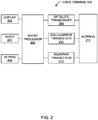
- FIG. 2 illustrates the components of an exemplary user terminal 104, according to one example.
- the user terminal 104 includes a microprocessor 200 for controlling the terminal's 104 operations; one or more input/output components coupled to the microprocessor 200, such as display 202, audio 204 and keypad 206, for inputting and outputting data as directed by the microprocessor 200; a plurality of transmit/receive components coupled to the microprocessor 200 for communicating with a plurality of communications networks as directed by the microprocessor 200, wherein the transmit/receive components include a satellite transceiver 208 for communicating with the satellite network 100, a cellular/PCS transceiver 210 for communicating with a cellular/PCS network, a WLAN/PAN transceiver 212 for communicating with other WLAN/PAN elements, as well as transmit/receive components (not shown) for communicating with other networks; and an integrated antenna 218 coupled to the transmit/receive components, such as transceivers 208, 210 and 212, for
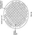
- FIGS. 3A and 3B illustrate alternative examples for the antenna 218 used by the user terminal 104, according to one example.
- the antenna 218 comprises a reconfigurable phased array antenna 218 that is omni-directional for use during signal acquisition and directional for use during normal communication.
- the phased array antenna 218 is configured to be omni-directional to acquire the strongest satellite 102 signal among the signals in the field of regard, but the phased array antenna 218 is configured to be directional to provide the highest gain during normal communication. In this manner, the user terminal 104 optimizes and accelerates the satellite 102 signal acquisition process.
- the elements 300 are individually selectable by the user terminal 104, such that the phases and/or amplitudes of signals feeding the elements 300 are varied to create a desired radiation pattern for the antenna 218.
- the resulting beams of the desired radiation pattern are formed and then steered by sequentially shifting the phase and/or amplitude of the signals feeding each element 300 to provide a constructive desired signal and/or destructive interference.
- the attributes of the signals received from one or more of the satellites 102 are analyzed by the user terminal 104, and a preferred satellite 102 is then selected by the user terminal 104 based on the attributes of the signals.
- the phased array antenna 218 is re-configured to be directional towards the selected satellite 102 to provide a higher gain during normal communication with the selected satellite 102. Specifically, once the strongest satellite signal is acquired, the phased array antenna 218 is reconfigured to its beamforming mode to form a beam that is pointed at the satellite 102.
- ephemeris data broadcast by the satellites 102 is used to slew/point the antenna 218 and its beam at the selected satellite 102, to keep tracking the selected satellite 102 after its signal is acquired.
- the ephemeris data comprises the location for the satellites 102 in the constellation at a particular point in time, and is broadcast by each of the satellites 102 on a low data rate pilot signal.
- the ephemeris data broadcast by the satellites 102 is also used by the user terminal 104 to perform handoffs between satellites 102 in the constellation. Specifically, the user terminal 104 performs a "make before break" seamless satellite-to-satellite handover using the ephemeris data broadcast by the satellites 102 to select a next satellite 102 for use, before it terminates communication with the current satellite 102.
- the user terminal 104 uses the ephemeris data broadcast by the satellites 102 to acquire the signals from the next satellite 102 either with a wide beam (e.g., an omni-directional or spoiled beam) or another high-gain beam (e.g., a directional beam) pointing at the next satellite 102 for a satellite-to-satellite handover.
- a wide beam e.g., an omni-directional or spoiled beam
- another high-gain beam e.g., a directional beam
- FIGS. 4A, 4B and 4C are graphs of theta (degrees) vs. amplitude (dB), illustrating the difference in beam patterns of the antenna 218 for acquisition mode vs. tracking mode.
- FIG. 4A illustrates an array beam pattern for the antenna 218 in an acquisition mode, using one of the elements 300 of the antenna 218 for a wider beamwidth with lower gain that allows the antenna 218 to "see” as many satellite 102 signals as possible in the field of regard.
- FIG. 4A illustrates a plane cut of a one-element 300 beam used for acquisition, with a +/- 10 degree beam width (at -3 dB to -5 dB down from the peak).
- FIG. 4C illustrates an array beam pattern for the antenna 218 in an acquisition mode, using a "spoiled beam” for a wider beamwidth with lower gain that allows the antenna 218 to "see” as many satellite 102 signals as possible in the field of regard.
- FIG. 4C illustrates a plane cut of an all element 300 spoiled beam for acquisition, with a +/-3 degree beam width (at -3dB down from the peak). Note that the spoiled beam shown in FIG. 4C has a higher edge directivity ( ⁇ 18.0 dBi within the beamwidth of +/- 10 degrees) than that of the single element beam ( ⁇ 15.9 dBi) shown in FIG. 4A .
- FIGS. 5A, 5B and 5C are diagrams (in degrees), illustrating the difference in beam patterns of the antenna 218 for acquisition mode vs. tracking mode.
- FIG. 5A is a contour plot of a single element 300 beam used for acquisition mode.
- the antenna 218 in acquisition mode uses a single element 300 radiation pattern, with a wide beam at a lower gain (as compared to FIG. 5B ).
- the three contours shown in FIG. 5A are at -2 dB down from the beam peak (500), -4 dB down from the beam peak (502), and -6 dB down from the beam peak (504). Also shown is the 20 degree diameter circle.
- FIG. 5B is a contour plot of an all element 300 beam used for tracking mode.
- the antenna 218 in tracking mode uses a 1015 element 300 radiation pattern, with a narrow beam at a higher gain (as compared to FIGS. 5A and 5C ) for a 10-degree scan angle.
- the three beams are: a first beam 506 scanned at 0 degrees, a second beam 508 scanned at about 9 degrees elevation, and a third beam 510 scanned at about 9 degrees azimuth.
- the contours are at -3 dB and -10 dB down from the beam peak.
- Block 600 represents the network 100 transmitting satellite ephemeris data to the satellites 102.
- Block 602 represents the satellites 102 broadcasting the satellite ephemeris data to the user terminals 104.
- the reconfigurable phased array antenna 218 is stationary (not slewing) when the user terminal 104 is in acquisition mode. In another example, the reconfigurable phased array antenna 218 is slewed to establish an initial pointing vector comprised of azimuth and elevation prior to acquisition of pilot signals from a plurality of satellites 102 within the field of regard, but the reconfigurable phased array antenna 218 is not slewed once the field of regard is selected.
- Block 606 represents the user terminal 104 receiving pilot signals from a plurality of satellites 102 within the field of regard using the reconfigurable phased array antenna 218.
- Block 608 represents the user terminal 104 determining one or more attributes of the pilot signals received from each of the satellites 102 and then selecting one of the plurality of satellites 102 for communication with the reconfigurable phased array antenna 218 based on the attributes of the received signals.
- the one or more attributes comprise signal strength, signal quality, or proximity to other signals.
- Block 610 represents the user terminal 104 obtaining the satellite ephemeris data, as well as other broadcast system information, from the selected satellite 102.
- Block 612 represents the user terminal 104, in tracking mode, switching to a directional (high gain, beamforming) mode for the reconfigurable phased array antenna 218, with the elements 300 of the antenna 218 forming a narrow beam pointed at the selected satellite 102, and establishing communications with the selected satellite 102 using the reconfigurable phased array antenna 218.
- the user terminal 104 tracks the selected satellite 102 using the ephemeris data to position the beams formed by the reconfigurable phased array antenna 218, wherein an initial pointing vector comprised of an azimuth and elevation and an initial tracking vector comprised of a flight path are determined based on the ephemeris data for the satellites 102 relative to a current terrestrial or airborne location of the user terminal 104 and the reconfigurable phased array antenna 218.
- Block 614 represents the user terminal 104 performing normal communications, i.e., transmitting and/or receiving, with the selected satellite 102, including applications such as consumer, commercial and military communications, satellite television, satellite radio, and Internet access.
- Block 616 represents the satellites 102 transmitting and/or receiving normal communications with the user terminals 104.
- Block 618 represents the network 100 transmitting and/or receiving normal communications with the satellites 102.
Landscapes
- Engineering & Computer Science (AREA)
- Computer Networks & Wireless Communication (AREA)
- Signal Processing (AREA)
- Physics & Mathematics (AREA)
- General Physics & Mathematics (AREA)
- Astronomy & Astrophysics (AREA)
- Aviation & Aerospace Engineering (AREA)
- Radar, Positioning & Navigation (AREA)
- Remote Sensing (AREA)
- Variable-Direction Aerials And Aerial Arrays (AREA)
- Radio Relay Systems (AREA)
- Position Fixing By Use Of Radio Waves (AREA)
Abstract
Description
- The present invention relates to satellite communications networks, and in particular to an accelerated satellite acquisition scheme for satellite-capable user terminals.
- In recent years, there has been an increased demand for wireless communications services. Various capabilities and services are being integrated into mobile devices, including the use of satellites operating in low Earth orbit (LEO) and medium Earth orbit (MEO), as well as geostationary or geosynchronous Earth orbit (GEO).
- LEO is the simplest and cheapest for satellite placement, and it provides high bandwidth and low latency for communications services. Similarly, the most common use for satellites in MEO is for communications services, although navigation and geodetic/space environment science applications use MEO as well.
- A problem exists in that satellites in both LEO and MEO are not visible from any given point on the Earth at all times, unlike GEO satellites. Because these LEO and MEO orbits are not geostationary, a network or constellation of satellites is required to provide continuous communications services coverage.
- For both LEO and MEO satellites, current satellite signal acquisition techniques are based on using an omni-directional antenna in a user terminal, which can see most of the satellites in a field of regard (FoR) or field of view (FoV). The field of regard is the total area that can be captured by an antenna, while the field of view is an angular cone perceivable by the antenna at a particular time instant. The field of regard is typically much larger than the field of view, although the field of regard and field of view coincide for a stationary antenna.
- When the user terminal is turned on, it needs to acquire the strongest satellite signal among the many signals in the field of regard or field of view.
- However, with the advent of satellite broadband communications services, the antenna in the user terminal needs to be directional for higher gain. Specifically, this feature benefits the normal communication channel speed, but it is not desired during acquisition of the satellite signal.
- What is needed, then, is an omni-directional antenna for use during signal acquisition, and a directional antenna for use during normal communications. The present invention satisfies this need.
- To overcome the limitations in the prior art described above, and to overcome other limitations that will become apparent upon reading and understanding the present specification, the present invention discloses a method and apparatus for establishing communication with a satellite by providing a user terminal including a reconfigurable phased array antenna having a plurality of antenna elements. The user terminal is operable for: broadening a field of regard of the reconfigurable phased array antenna; receiving signals from a plurality of satellites within the field of regard using the reconfigurable phased array antenna; determining one or more attributes of the received signals for each of the satellites; and selecting one of the plurality of satellites for communication based on the attributes of the received signals.
- Prior to selecting the field of regard, the reconfigurable phased array antenna is stationary. Alternatively, the reconfigurable phased array antenna is slewed to establish an initial pointing vector comprised of an azimuth and elevation prior to selecting the field of regard, but the reconfigurable phased array antenna is not slewed once the field of regard is selected.
- The field of regard is broadened by using a lesser number than a total number of the plurality of antenna elements of the reconfigurable phased array antenna. This includes selecting one antenna element from the plurality of antenna elements of the reconfigurable phased array antenna, or selecting a sub-array of two or more antenna elements from the plurality of antenna elements of the reconfigurable phased array antenna.
- The field of regard is also broadened by using a spoiled beam by changing at least one of a phase and amplitude for one or more of the plurality of antenna elements of the reconfigurable phased array antenna to spread a beam width. The spoiled beam is generated by introducing a phase difference that alters a coherence of the received signals at the reconfigurable phased array antenna.
- The attributes used for selecting the satellite comprise signal strength, signal quality, or proximity to other signals.
- After the satellite has been selected, the user terminal is operable for: switching to a directional mode for the reconfigurable phased array antenna; establishing the communication with the selected satellite using the reconfigurable phased array antenna; and tracking the selected satellite.
- When tracking the selected satellite, an initial pointing vector comprised of an azimuth and elevation and an initial tracking vector comprised of a flight path are determined for the reconfigurable phased array antenna based on ephemeris data for the satellites relative to a current terrestrial or airborne location of the user terminal.
- Referring now to the drawings in which like reference numbers represent corresponding parts throughout:
-
FIG. 1 is a diagram showing an exemplary communications system, according to one example. -
FIG. 2 illustrates the components of the satellite-capable mobile user terminal, according to one example. -
FIGS. 3A and3B illustrate alternative examples for the antenna used by the user terminal, according to one example. -
FIGS. 4A, 4B and 4C are graphs of theta (degrees) vs. amplitude (dB), illustrating the difference in beam patterns of the antenna for acquisition mode vs. tracking mode, according to one example. -
FIGS. 5A, 5B and 5C are diagrams (in degrees), illustrating the difference in beam patterns of the antenna for acquisition mode vs. tracking mode, according to one example. -
FIG. 6 is a flowchart that illustrates the steps performed by the network, satellites and user terminals, according to one example. - In the following description of the preferred example, reference is made to the accompanying drawings which form a part hereof, and in which is shown by way of illustration a specific example in which the invention may be practiced. It is to be understood that other examples may be utilized and structural changes may be made without departing from the scope of the present invention.
-
FIG. 1 is a diagram showing an exemplary communications system, according to one example. The communications system comprises asatellite network 100 that includes one ormore satellites 102, and one or more satellite-capable user terminals 104 are provided, which are also labeled as a terrestrial user terminal 104 and an airborne user terminal 104 inFIG. 1 , for communicating with thesatellites 102. - Also in the example of
FIG. 1 , thesatellite network 100 includes aground station 106 for transmitting and receiving data to and from thesatellites 102. Thesatellite network 100 may also interface to one or more other satellite, terrestrial and/or airborne networks (not shown), for example, a cellular or personal communications systems (PCS) network, wireless local area networks (WLANs), personal area networks (PANs), or other networks. The user terminals 104 may also operate with the other satellite, terrestrial and/or airborne networks. - There are a number of benefits to using a
satellite network 100. One benefit is the ubiquitous coverage of thesatellite network 100 as an alternative network option to the terrestrial networks. Another benefit of thesatellite network 100 is surge capacity to overcome congestion in the terrestrial networks. Asatellite network 100 also transcends outages in the terrestrial networks. -
FIG. 2 illustrates the components of an exemplary user terminal 104, according to one example. The user terminal 104 includes amicroprocessor 200 for controlling the terminal's 104 operations; one or more input/output components coupled to themicroprocessor 200, such asdisplay 202,audio 204 andkeypad 206, for inputting and outputting data as directed by themicroprocessor 200; a plurality of transmit/receive components coupled to themicroprocessor 200 for communicating with a plurality of communications networks as directed by themicroprocessor 200, wherein the transmit/receive components include asatellite transceiver 208 for communicating with thesatellite network 100, a cellular/PCS transceiver 210 for communicating with a cellular/PCS network, a WLAN/PAN transceiver 212 for communicating with other WLAN/PAN elements, as well as transmit/receive components (not shown) for communicating with other networks; and an integrated antenna 218 coupled to the transmit/receive components, such astransceivers -
FIGS. 3A and3B illustrate alternative examples for the antenna 218 used by the user terminal 104, according to one example. In both examples, the antenna 218 comprises a reconfigurable phased array antenna 218 that is omni-directional for use during signal acquisition and directional for use during normal communication. Specifically, the phased array antenna 218 is configured to be omni-directional to acquire thestrongest satellite 102 signal among the signals in the field of regard, but the phased array antenna 218 is configured to be directional to provide the highest gain during normal communication. In this manner, the user terminal 104 optimizes and accelerates thesatellite 102 signal acquisition process. - As shown in both
FIGS. 3A and3B , the phased array antenna 218 is comprised of an array of radiatingelements 300 formed on asubstrate 302. Eachelement 300 is shown as a square feature, but could comprise a patch, dipole, slot or other type ofantenna element 300. Thesubstrate 302 is shown as a circular feature, but could comprise any shape. - The
elements 300 are individually selectable by the user terminal 104, such that the phases and/or amplitudes of signals feeding theelements 300 are varied to create a desired radiation pattern for the antenna 218. The resulting beams of the desired radiation pattern are formed and then steered by sequentially shifting the phase and/or amplitude of the signals feeding eachelement 300 to provide a constructive desired signal and/or destructive interference. - During acquisition of a
satellite 102 signal, the phased array antenna 218 is re-configured, either by using only oneelement 300 to broaden the field of regard, or by using a "spoiled beam" with a subset or all of theelements 300 to broaden the field of regard, as well as to increase a receiving area for an increased signal-to-noise ratio (SNR).FIG. 3A illustrates one example, wherein only one of theelements 300 of the phased array antenna 218 is turned on for receiving, as indicated by the fill pattern, wherein thissingle element 300 has a much broader beam looking at a broadened field of regard, so it can see asmany satellites 102 as possible.FIG. 3B illustrates another example, wherein a spoiled beam is formed using a subset or all of theelements 300, as indicated by the fill patterns, to broaden the field of regard, but with higher antenna 218 directivity to increase the signal-to-noise ratio. - The attributes of the signals received from one or more of the
satellites 102 are analyzed by the user terminal 104, and apreferred satellite 102 is then selected by the user terminal 104 based on the attributes of the signals. After thesatellite 102 has been selected, the phased array antenna 218 is re-configured to be directional towards the selectedsatellite 102 to provide a higher gain during normal communication with the selectedsatellite 102. Specifically, once the strongest satellite signal is acquired, the phased array antenna 218 is reconfigured to its beamforming mode to form a beam that is pointed at thesatellite 102. - In one example, ephemeris data broadcast by the
satellites 102 is used to slew/point the antenna 218 and its beam at the selectedsatellite 102, to keep tracking the selectedsatellite 102 after its signal is acquired. The ephemeris data comprises the location for thesatellites 102 in the constellation at a particular point in time, and is broadcast by each of thesatellites 102 on a low data rate pilot signal. - The ephemeris data broadcast by the
satellites 102 is also used by the user terminal 104 to perform handoffs betweensatellites 102 in the constellation. Specifically, the user terminal 104 performs a "make before break" seamless satellite-to-satellite handover using the ephemeris data broadcast by thesatellites 102 to select anext satellite 102 for use, before it terminates communication with thecurrent satellite 102. Using the ephemeris data broadcast by thesatellites 102, the user terminal 104 knows the positions of thesatellites 102 in the constellation and acquires the signals from thenext satellite 102 either with a wide beam (e.g., an omni-directional or spoiled beam) or another high-gain beam (e.g., a directional beam) pointing at thenext satellite 102 for a satellite-to-satellite handover. -
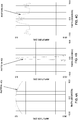
FIGS. 4A, 4B and 4C are graphs of theta (degrees) vs. amplitude (dB), illustrating the difference in beam patterns of the antenna 218 for acquisition mode vs. tracking mode. -
FIG. 4A illustrates an array beam pattern for the antenna 218 in an acquisition mode, using one of theelements 300 of the antenna 218 for a wider beamwidth with lower gain that allows the antenna 218 to "see" asmany satellite 102 signals as possible in the field of regard. Specifically,FIG. 4A illustrates a plane cut of a one-element 300 beam used for acquisition, with a +/- 10 degree beam width (at -3 dB to -5 dB down from the peak). -
FIG. 4B illustrates an array beam pattern for the antenna 218 in a tracking mode, using all (or most) of theelements 300 of the antenna 218 for narrow beamwidth and higher gain that allows the antenna 218 to provide greater bandwidth to the selectedsatellite 102. Specifically,FIG. 4B illustrates a plane cut of an all-element 300 narrow beam for tracking, with a +/-0.5 degree beam width (at -3dB down from the peak). -
FIG. 4C illustrates an array beam pattern for the antenna 218 in an acquisition mode, using a "spoiled beam" for a wider beamwidth with lower gain that allows the antenna 218 to "see" asmany satellite 102 signals as possible in the field of regard. Specifically,FIG. 4C illustrates a plane cut of an allelement 300 spoiled beam for acquisition, with a +/-3 degree beam width (at -3dB down from the peak). Note that the spoiled beam shown inFIG. 4C has a higher edge directivity (∼ 18.0 dBi within the beamwidth of +/- 10 degrees) than that of the single element beam (∼ 15.9 dBi) shown inFIG. 4A . -
FIGS. 5A, 5B and 5C are diagrams (in degrees), illustrating the difference in beam patterns of the antenna 218 for acquisition mode vs. tracking mode. -
FIG. 5A is a contour plot of asingle element 300 beam used for acquisition mode. In this example, the antenna 218 in acquisition mode uses asingle element 300 radiation pattern, with a wide beam at a lower gain (as compared toFIG. 5B ). The three contours shown inFIG. 5A are at -2 dB down from the beam peak (500), -4 dB down from the beam peak (502), and -6 dB down from the beam peak (504). Also shown is the 20 degree diameter circle. -
FIG. 5B is a contour plot of an allelement 300 beam used for tracking mode. In this example, the antenna 218 in tracking mode uses a 1015element 300 radiation pattern, with a narrow beam at a higher gain (as compared toFIGS. 5A and 5C ) for a 10-degree scan angle. The three beams are: afirst beam 506 scanned at 0 degrees, asecond beam 508 scanned at about 9 degrees elevation, and athird beam 510 scanned at about 9 degrees azimuth. The contours are at -3 dB and -10 dB down from the beam peak. -
FIG. 5C is a contour plot of an allelement 300 spoiled beam used for acquisition mode. In this example, the antenna 218 in acquisition mode uses a 1015element 300 radiation pattern, with a wide "spoiled beam" at a lower gain (as compared toFIG. 5B ), with 17 dBi and 16.0 dBi contours for the spoiled beam. -
FIG. 6 is a flowchart that illustrates the steps performed by thenetwork 100,satellites 102 and user terminals 104 in a method of establishing communication with asatellite 102, according to one example. -
Block 600 represents thenetwork 100 transmitting satellite ephemeris data to thesatellites 102. - Block 602 represents the
satellites 102 broadcasting the satellite ephemeris data to the user terminals 104. - Block 604 represents a user terminal 104, in acquisition mode after being turned on, broadening a field of regard of the reconfigurable phased array antenna 218 having a plurality of
antenna elements 300. The broadened field of regard results in a wider beamwidth with lower gain that allows the antenna 218 to "see" as many signal sources, e.g.,satellites 102, as possible. - In one example, the reconfigurable phased array antenna 218 is stationary (not slewing) when the user terminal 104 is in acquisition mode. In another example, the reconfigurable phased array antenna 218 is slewed to establish an initial pointing vector comprised of azimuth and elevation prior to acquisition of pilot signals from a plurality of
satellites 102 within the field of regard, but the reconfigurable phased array antenna 218 is not slewed once the field of regard is selected. - In one example, the user terminal 104 broadens the field of regard by using a lesser number than a total number of the plurality of
antenna elements 300 of the reconfigurable phased array antenna 218. This may further comprise selecting oneantenna element 300 from the plurality ofantenna elements 300 of the reconfigurable phased array antenna 218 (e.g., any one of theantenna elements 300 may be selected to provide redundancy and fault tolerance), or this may further comprise selecting a sub-array of two ormore antenna elements 300 from the plurality ofantenna elements 300 of the reconfigurable phased array antenna 218. - In another example, the user terminal 104 broadens the field of regard by using a spoiled beam by changing at least one of a phase and amplitude for (each or adjacent ones) of the plurality of
antenna elements 300 of the reconfigurable phased array antenna 218 to spread a beam width. The spoiled beam is generated by introducing a phase difference that alters a coherence of the received signals at the reconfigurable phased array antenna 218. - Block 606 represents the user terminal 104 receiving pilot signals from a plurality of
satellites 102 within the field of regard using the reconfigurable phased array antenna 218. - Block 608 represents the user terminal 104 determining one or more attributes of the pilot signals received from each of the
satellites 102 and then selecting one of the plurality ofsatellites 102 for communication with the reconfigurable phased array antenna 218 based on the attributes of the received signals. In one example, the one or more attributes comprise signal strength, signal quality, or proximity to other signals. - Block 610 represents the user terminal 104 obtaining the satellite ephemeris data, as well as other broadcast system information, from the selected
satellite 102. - Block 612 represents the user terminal 104, in tracking mode, switching to a directional (high gain, beamforming) mode for the reconfigurable phased array antenna 218, with the
elements 300 of the antenna 218 forming a narrow beam pointed at the selectedsatellite 102, and establishing communications with the selectedsatellite 102 using the reconfigurable phased array antenna 218. Thereafter, the user terminal 104 tracks the selectedsatellite 102 using the ephemeris data to position the beams formed by the reconfigurable phased array antenna 218, wherein an initial pointing vector comprised of an azimuth and elevation and an initial tracking vector comprised of a flight path are determined based on the ephemeris data for thesatellites 102 relative to a current terrestrial or airborne location of the user terminal 104 and the reconfigurable phased array antenna 218. - Block 614 represents the user terminal 104 performing normal communications, i.e., transmitting and/or receiving, with the selected
satellite 102, including applications such as consumer, commercial and military communications, satellite television, satellite radio, and Internet access. - Block 616 represents the
satellites 102 transmitting and/or receiving normal communications with the user terminals 104. -
Block 618 represents thenetwork 100 transmitting and/or receiving normal communications with thesatellites 102. - Further, the disclosure comprises examples according to the following clauses:
- Clause 1. A method of establishing communication with a satellite, comprising:
- providing a user terminal (104) including a reconfigurable phased array antenna (214) having a plurality of antenna elements (300), wherein the user terminal (104) is operable for:
- broadening (604) a field of regard of the reconfigurable phased array antenna (214);
- receiving (606) signals from a plurality of satellites (102) within the field of regard using the reconfigurable phased array antenna (214);
- determining (608) one or more attributes of the received signals for each of the satellites (102); and
- selecting (608) one of the plurality of satellites (102) for communication based on the attributes of the received signals.
- Clause 2. The method of Clause 1, wherein the attributes comprise signal strength, signal quality, or proximity to other signals.
- Clause 3. The method of Clause 1, wherein broadening (604) the field of regard includes at least one of:
- using (604) a lesser number than a total number of the plurality of antenna elements (300) of the reconfigurable phased array antenna (214); and
- using (604) a spoiled beam by changing at least one of a phase and amplitude for one or more of the plurality of antenna elements (300) of the reconfigurable phased array antenna (214) to spread a beam width.
- Clause 4. The method of Clause 3, wherein using (604) a lesser number than a total number of the plurality of antenna elements (300) further comprises one of:
- selecting (604) one antenna element (300) from the plurality of antenna elements (300) of the reconfigurable phased array antenna (214); and
- selecting (604) a sub-array of two or more antenna elements (300) from the plurality of antenna elements (300) of the reconfigurable phased array antenna (214).
- Clause 5. The method of Clause 3, wherein the spoiled beam is generated by introducing a phase difference that alters a coherence of the received signals at the reconfigurable phased array antenna (214).
- Clause 6. The method of Clause 1, wherein, after the satellite (102) has been selected, the user terminal (104) is operable for:
- switching (612) to a directional mode for the reconfigurable phased array antenna (214);
- establishing (612) the communication with the selected satellite (102) using the reconfigurable phased array antenna (214); and
- tracking (614) the selected satellite (102).
- Clause 7. The method of Clause 6, wherein tracking (614) the selected satellite (102) comprises determining (614) an initial pointing vector comprised of an azimuth and elevation and an initial tracking vector comprised of a flight path for the reconfigurable phased array antenna (214) based on ephemeris data for the satellites (102) relative to a current terrestrial or airborne location of the user terminal (104).
- Clause 8. The method of Clause 1, wherein the reconfigurable phased array antenna (214) is stationary prior to selecting the field of regard.
- Clause 9. The method of Clause 1, wherein the reconfigurable phased array antenna (214) is slewed to establish an initial pointing vector comprised of an azimuth and elevation prior to selecting the field of regard, but the reconfigurable phased array antenna (214) is not slewed once the field of regard is selected.
-
Clause 10. An apparatus for establishing communication with a satellite (102), comprising:- a user terminal (104) including a reconfigurable phased array antenna (214) having a plurality of antenna elements (300), wherein the user terminal (104) is operable for:
- broadening (604) a field of regard of the reconfigurable phased array antenna (214);
- receiving (606) signals from a plurality of satellites (102) within the field of regard using the reconfigurable phased array antenna (214);
- determining (608) one or more attributes of the received signals for each of the satellites (102); and
- selecting (608) one of the plurality of satellites (102) for communication based on the determined attributes of the received signals.
- a user terminal (104) including a reconfigurable phased array antenna (214) having a plurality of antenna elements (300), wherein the user terminal (104) is operable for:
- Clause 11. The apparatus of
Clause 10, wherein the attributes comprise signal strength, signal quality, or proximity to other signals. - Clause 12. The apparatus of
Clause 10, wherein broadening (604) the field of regard includes at least one of:- using (604) a lesser number than a total number of the plurality of antenna elements (300) of the reconfigurable phased array antenna (214); and
- using (604) a spoiled beam by changing at least one of a phase and amplitude for one or more of the plurality of antenna elements (300) of the reconfigurable phased array antenna (214) to spread a beam width.
- Clause 13. The apparatus of Clause 12, wherein using (604) a lesser number than a total number of the plurality of antenna elements (300) further comprises one of:
- selecting (604) one antenna element (300) from the plurality of antenna elements (300) of the reconfigurable phased array antenna (214); and
- selecting (604) a sub-array of two or more antenna elements (300) from the plurality of antenna elements (300) of the reconfigurable phased array antenna (214).
- Clause 14. The apparatus of Clause 12, wherein the spoiled beam is generated by introducing a phase difference that alters a coherence of the received signals at the reconfigurable phased array antenna (214).
- Clause 15. The apparatus of
Clause 10, wherein, after the satellite (102) has been selected, the user terminal (104) is operable for:- switching (612) to a directional mode for the reconfigurable phased array antenna (214);
- establishing (612) the communication with the selected satellite (102) using the reconfigurable phased array antenna (214); and
- tracking (612) the selected satellite (102).
- Clause 16. The apparatus of Clause 15, wherein tracking the selected satellite (102) comprises determining an initial pointing vector comprised of an azimuth and elevation and an initial tracking vector comprised of a flight path for the reconfigurable phased array antenna (214) based on ephemeris data for the satellites (102) relative to a current terrestrial or airborne location of the user terminal (104).
- Clause 17. The apparatus of
Clause 10, wherein the reconfigurable phased array antenna (214) is stationary prior to selecting the field of regard. - Clause 18. The apparatus of
Clause 10, wherein the reconfigurable phased array antenna (214) is slewed to establish an initial pointing vector comprised of an azimuth and elevation prior to selecting the field of regard, but the reconfigurable phased array antenna (214) is not slewed once the field of regard is selected. - Clause 19. An apparatus for establishing communication with a signal source (102), comprising:
- a reconfigurable phased array antenna (214) having a plurality of antenna elements (300), wherein:
- a field of regard of the reconfigurable phased array antenna (214) is broadened (604) prior to receiving (606) signals from the signal source (102);
- the reconfigurable phased array antenna (214) is switched (612) to a directional mode when establishing (612) communications with the signal source (102) and tracking (612) the signal source (102).
- a reconfigurable phased array antenna (214) having a plurality of antenna elements (300), wherein:
- Clause 20. The apparatus of Clause 19, wherein the field of regard is broadened (604) by at least one of:
- using (604) a lesser number than a total number of the plurality of antenna elements (300) of the reconfigurable phased array antenna (214); and
- using (604) a spoiled beam by changing at least one of a phase and amplitude for one or more of the plurality of antenna elements (300) of the reconfigurable phased array antenna (214) to spread a beam width.
- Clause 21. The apparatus of Clause 20, wherein using (604) a lesser number than a total number of the plurality of antenna elements (300) further comprises one of:
- selecting (604) one antenna element (300) from the plurality of antenna elements (300) of the reconfigurable phased array antenna (214); and
- selecting (604) a sub-array of two or more antenna elements (300) from the plurality of antenna elements (300) of the reconfigurable phased array antenna (214).
- Clause 22. The apparatus of Clause 20, wherein the spoiled beam is generated by introducing a phase difference that alters a coherence of the received signals at the reconfigurable phased array antenna (214).
- Clause 23. The apparatus of Clause 19, wherein tracking the signal source (102) comprises determining an initial pointing vector comprised of an azimuth and elevation and an initial tracking vector comprised of a flight path for the reconfigurable phased array antenna (214) based on ephemeris data for the signal source (102) relative to a current terrestrial or airborne location of a user terminal (104).
- Clause 24. The apparatus of Clause 19, wherein the reconfigurable phased array antenna (214) is stationary prior to selecting the field of regard.
- Clause 25. The apparatus of Clause 19, wherein the reconfigurable phased array antenna (214) is slewed to establish an initial pointing vector comprised of an azimuth and elevation prior to selecting the field of regard, but the reconfigurable phased array antenna (214) is not slewed once the field of regard is selected.
Claims (15)
- A method of establishing communication with a satellite, comprising:providing a user terminal (104) including a reconfigurable phased array antenna (214) having a plurality of antenna elements (300), wherein the user terminal (104) is operable for:broadening (604) a field of regard of the reconfigurable phased array antenna (214);receiving (606) signals from a plurality of satellites (102) within the field of regard using the reconfigurable phased array antenna (214);determining (608) one or more attributes of the received signals for each of the satellites (102); andselecting (608) one of the plurality of satellites (102) for communication based on the attributes of the received signals.
- The method of claim 1, wherein the attributes comprise signal strength, signal quality, or proximity to other signals.
- The method of claim 1 or 2, wherein broadening (604) the field of regard includes at least one of:using (604) a lesser number than a total number of the plurality of antenna elements (300) of the reconfigurable phased array antenna (214); andusing (604) a spoiled beam by changing at least one of a phase and amplitude for one or more of the plurality of antenna elements (300) of the reconfigurable phased array antenna (214) to spread a beam width.
- The method of claim 3, wherein using (604) a lesser number than a total number of the plurality of antenna elements (300) further comprises one of:selecting (604) one antenna element (300) from the plurality of antenna elements (300) of the reconfigurable phased array antenna (214); andselecting (604) a sub-array of two or more antenna elements (300) from the plurality of antenna elements (300) of the reconfigurable phased array antenna (214).
- The method of claim 3 or 4, wherein the spoiled beam is generated by introducing a phase difference that alters a coherence of the received signals at the reconfigurable phased array antenna (214).
- The method of any one of claims 1-5, wherein, after the satellite (102) has been selected, the user terminal (104) is operable for:switching (612) to a directional mode for the reconfigurable phased array antenna (214);establishing (612) the communication with the selected satellite (102) using the reconfigurable phased array antenna (214); andtracking (614) the selected satellite (102).
- The method of claim 6, wherein tracking (614) the selected satellite (102) comprises determining (614) an initial pointing vector comprised of an azimuth and elevation and an initial tracking vector comprised of a flight path for the reconfigurable phased array antenna (214) based on ephemeris data for the satellites (102) relative to a current terrestrial or airborne location of the user terminal (104).
- The method of any one of claims 1-7, wherein the reconfigurable phased array antenna (214) is stationary prior to selecting the field of regard.
- The method of any one of claims 1-8, wherein the reconfigurable phased array antenna (214) is slewed to establish an initial pointing vector comprised of an azimuth and elevation prior to selecting the field of regard, but the reconfigurable phased array antenna (214) is not slewed once the field of regard is selected.
- An apparatus for establishing communication with a signal source (102), comprising:a reconfigurable phased array antenna (214) having a plurality of antenna elements (300), wherein:a field of regard of the reconfigurable phased array antenna (214) is broadened (604) prior to receiving (606) signals from the signal source (102);the reconfigurable phased array antenna (214) is switched (612) to a directional mode when establishing (612) communications with the signal source (102) and tracking (612) the signal source (102).
- The apparatus of claim 10, wherein the field of regard is broadened (604) by at least one of:using (604) a lesser number than a total number of the plurality of antenna elements (300) of the reconfigurable phased array antenna (214); andusing (604) a spoiled beam by changing at least one of a phase and amplitude for one or more of the plurality of antenna elements (300) of the reconfigurable phased array antenna (214) to spread a beam width.
- The apparatus of claim 11, wherein using (604) a lesser number than a total number of the plurality of antenna elements (300) further comprises one of:selecting (604) one antenna element (300) from the plurality of antenna elements (300) of the reconfigurable phased array antenna (214); andselecting (604) a sub-array of two or more antenna elements (300) from the plurality of antenna elements (300) of the reconfigurable phased array antenna (214).
- The apparatus of claim 11 or 12, wherein the spoiled beam is generated by introducing a phase difference that alters a coherence of the received signals at the reconfigurable phased array antenna (214).
- The apparatus of any one of claims 10-13, wherein tracking the signal source (102) comprises determining an initial pointing vector comprised of an azimuth and elevation and an initial tracking vector comprised of a flight path for the reconfigurable phased array antenna (214) based on ephemeris data for the signal source (102) relative to a current terrestrial or airborne location of a user terminal (104).
- The apparatus of any one of claims 10-14, wherein the reconfigurable phased array antenna (214) is slewed to establish an initial pointing vector comprised of an azimuth and elevation prior to selecting the field of regard, but the reconfigurable phased array antenna (214) is not slewed once the field of regard is selected.
Applications Claiming Priority (1)
| Application Number | Priority Date | Filing Date | Title |
|---|---|---|---|
| US15/375,490 US20180164441A1 (en) | 2016-12-12 | 2016-12-12 | Accelerated satellite acquisition scheme |
Publications (2)
| Publication Number | Publication Date |
|---|---|
| EP3334060A1 true EP3334060A1 (en) | 2018-06-13 |
| EP3334060B1 EP3334060B1 (en) | 2025-07-23 |
Family
ID=60201329
Family Applications (1)
| Application Number | Title | Priority Date | Filing Date |
|---|---|---|---|
| EP17197858.8A Active EP3334060B1 (en) | 2016-12-12 | 2017-10-23 | Accelerated satellite acquisition method by broadening of the field of regard of a reconfigurable phased array antenna. |
Country Status (7)
| Country | Link |
|---|---|
| US (2) | US20180164441A1 (en) |
| EP (1) | EP3334060B1 (en) |
| JP (1) | JP7411321B2 (en) |
| KR (1) | KR102360451B1 (en) |
| CN (1) | CN108234012B (en) |
| CA (1) | CA2982038C (en) |
| RU (1) | RU2756402C2 (en) |
Cited By (1)
| Publication number | Priority date | Publication date | Assignee | Title |
|---|---|---|---|---|
| WO2024107919A1 (en) * | 2022-11-18 | 2024-05-23 | Gogo Business Aviation Llc | Systems and methods for satellite selection using beamscanning techniques |
Families Citing this family (19)
| Publication number | Priority date | Publication date | Assignee | Title |
|---|---|---|---|---|
| US10128570B2 (en) * | 2016-10-13 | 2018-11-13 | The Boeing Company | System and method for wireless communications using an adaptable diamond phased array antenna system |
| US10725182B2 (en) * | 2018-01-04 | 2020-07-28 | Interstate Electronics Corporation | Systems and methods for providing anti-spoofing capability to a global navigation satellite system receiver |
| CN111130615B (en) * | 2018-10-30 | 2021-06-22 | 华为技术有限公司 | APT subsystem and communication system of spacecraft |
| US10574337B1 (en) | 2019-02-11 | 2020-02-25 | Gogo Llc | Multi-constellation satellite terminal |
| CN111698761B (en) * | 2019-03-15 | 2021-10-22 | 华为技术有限公司 | Communication method, device, equipment and system |
| CN110401034B (en) * | 2019-08-13 | 2024-02-13 | 中国电子科技集团公司第五十四研究所 | A communication and navigation integrated integrated antenna |
| CN111464940B (en) * | 2020-04-14 | 2021-03-30 | 清华大学 | Method and system for scheduling communication-guide integrated constellation beams |
| CA3205427A1 (en) | 2021-01-06 | 2022-07-14 | Aura Network Systems, Inc. | Systems and methods for managing radio frequency spectrum in ground to aerial vehicle communications |
| MX2023011263A (en) * | 2021-03-22 | 2024-01-05 | Aura Network Systems Inc | Systems and methods for flight plan initiated beam/null forming antenna control. |
| WO2022256809A1 (en) | 2021-06-01 | 2022-12-08 | Aura Network Systems, Inc. | Systems and methods for flight plan specific distributed ledger based aviation data link security |
| CN114280647B (en) * | 2021-12-28 | 2025-02-25 | 西安闻泰信息技术有限公司 | Indoor positioning method, device and system, electronic equipment and storage medium |
| KR20240132509A (en) | 2022-01-13 | 2024-09-03 | 아우라 네트워크 시스템즈, 인크. | Systems and methods for implementing air traffic control voice relay for unmanned aircraft systems over an aviation network |
| US20230327754A1 (en) * | 2022-04-08 | 2023-10-12 | All.Space Networks Limited | Method of operating a satellite communications terminal |
| US12284025B2 (en) * | 2022-05-11 | 2025-04-22 | Bao Tran | Mobile satellite communication system |
| EP4548499A1 (en) | 2022-07-12 | 2025-05-07 | Aura Network Systems, Inc. | Systems and methods for communication resource planning for ground to aerial vehicle communications |
| CN115694615B (en) * | 2022-11-03 | 2025-07-04 | 广东省大湾区集成电路与系统应用研究院 | A receiving device, a satellite communication system and a method for using the receiving device |
| CN116527109B (en) * | 2023-04-26 | 2024-02-23 | 中国人民解放军32039部队 | Method and device for space-based random access to intelligent spacecraft |
| KR102713238B1 (en) * | 2023-11-10 | 2024-10-04 | 한화시스템 주식회사 | satellite communications method and satellite communications apparatus |
| US20260086245A1 (en) * | 2024-09-24 | 2026-03-26 | Kymeta Corporation | Interference testing device, method, and system |
Citations (4)
| Publication number | Priority date | Publication date | Assignee | Title |
|---|---|---|---|---|
| US20030128159A1 (en) * | 2002-01-10 | 2003-07-10 | De La Chapelle Michael | 1-D electronic scanned satellite user terminal antenna |
| EP1802008A2 (en) * | 2005-12-23 | 2007-06-27 | Delphi Technologies, Inc. | Search algorithm for phased array antenna |
| US20160093950A1 (en) * | 2014-09-29 | 2016-03-31 | Maxtena | System in which a phased array antenna emulates lower directivity antennas |
| EP3010086A1 (en) * | 2014-10-13 | 2016-04-20 | Fraunhofer-Gesellschaft zur Förderung der angewandten Forschung e.V. | Phased array antenna |
Family Cites Families (17)
| Publication number | Priority date | Publication date | Assignee | Title |
|---|---|---|---|---|
| US6034634A (en) * | 1997-10-24 | 2000-03-07 | Telefonaktiebolaget L M Ericsson (Publ) | Terminal antenna for communications systems |
| US6111542A (en) * | 1998-04-06 | 2000-08-29 | Motorola, Inc. | Rotating electronically steerable antenna system and method of operation thereof |
| GB0016186D0 (en) * | 2000-06-30 | 2000-08-23 | Nokia Networks Oy | Antenna system |
| JP2002232335A (en) * | 2001-02-07 | 2002-08-16 | Nippon Hoso Kyokai <Nhk> | Diversity satellite broadcast receiving system and device |
| JP3999605B2 (en) * | 2002-08-23 | 2007-10-31 | 株式会社エヌ・ティ・ティ・ドコモ | Base station, mobile communication system, and communication method |
| JP3669355B2 (en) * | 2002-09-27 | 2005-07-06 | 日産自動車株式会社 | Satellite tracking antenna |
| US6961025B1 (en) * | 2003-08-18 | 2005-11-01 | Lockheed Martin Corporation | High-gain conformal array antenna |
| US7633442B2 (en) * | 2004-06-03 | 2009-12-15 | Interdigital Technology Corporation | Satellite communication subscriber device with a smart antenna and associated method |
| US8175532B2 (en) * | 2006-06-06 | 2012-05-08 | Qualcomm Incorporated | Apparatus and method for wireless communication via at least one of directional and omni-direction antennas |
| WO2009013527A1 (en) * | 2007-07-20 | 2009-01-29 | Astrium Limited | System for simplification of reconfigurable beam-forming network processing within a phased array antenna for a telecommunications satellite |
| US8027702B2 (en) * | 2008-03-11 | 2011-09-27 | Intel Corporation | Combined omni- and directional- communications in high-frequency wireless networks |
| US8120528B2 (en) * | 2008-05-14 | 2012-02-21 | Thomas Ronald Tessier | Apparatus for satellite telecommunications |
| JP5626688B2 (en) * | 2009-08-13 | 2014-11-19 | 国立大学法人 奈良先端科学技術大学院大学 | Wireless receiver |
| CN103364805B (en) * | 2013-07-19 | 2015-06-24 | 上海交通大学 | Method and system for automatically tracking medium earth orbit navigational satellite through servo antenna |
| US20170126296A1 (en) * | 2015-11-04 | 2017-05-04 | Futurewei Technologies, Inc. | System and Method for Large Scale Multiple Input Multiple Output Beamforming |
| CN205752544U (en) * | 2015-12-17 | 2016-11-30 | 中国电子科技集团公司第五十四研究所 | A dual-satellite dual-beam S-band satellite communication phased array antenna |
| US11374650B2 (en) * | 2016-05-27 | 2022-06-28 | Viasat, Inc. | Position-based access to satellite networks for satellite terminals |
-
2016
- 2016-12-12 US US15/375,490 patent/US20180164441A1/en not_active Abandoned
-
2017
- 2017-10-11 CA CA2982038A patent/CA2982038C/en active Active
- 2017-10-16 RU RU2017136438A patent/RU2756402C2/en active
- 2017-10-23 EP EP17197858.8A patent/EP3334060B1/en active Active
- 2017-10-27 KR KR1020170140763A patent/KR102360451B1/en active Active
- 2017-12-07 CN CN201711283362.6A patent/CN108234012B/en active Active
- 2017-12-07 JP JP2017234821A patent/JP7411321B2/en active Active
-
2023
- 2023-02-13 US US18/168,110 patent/US20230198166A1/en active Pending
Patent Citations (4)
| Publication number | Priority date | Publication date | Assignee | Title |
|---|---|---|---|---|
| US20030128159A1 (en) * | 2002-01-10 | 2003-07-10 | De La Chapelle Michael | 1-D electronic scanned satellite user terminal antenna |
| EP1802008A2 (en) * | 2005-12-23 | 2007-06-27 | Delphi Technologies, Inc. | Search algorithm for phased array antenna |
| US20160093950A1 (en) * | 2014-09-29 | 2016-03-31 | Maxtena | System in which a phased array antenna emulates lower directivity antennas |
| EP3010086A1 (en) * | 2014-10-13 | 2016-04-20 | Fraunhofer-Gesellschaft zur Förderung der angewandten Forschung e.V. | Phased array antenna |
Cited By (2)
| Publication number | Priority date | Publication date | Assignee | Title |
|---|---|---|---|---|
| WO2024107919A1 (en) * | 2022-11-18 | 2024-05-23 | Gogo Business Aviation Llc | Systems and methods for satellite selection using beamscanning techniques |
| US12088368B2 (en) | 2022-11-18 | 2024-09-10 | Gogo Business Aviation Llc | Systems and methods for satellite selection using beamscanning techniques |
Also Published As
| Publication number | Publication date |
|---|---|
| RU2017136438A3 (en) | 2020-10-30 |
| CA2982038A1 (en) | 2018-06-12 |
| US20230198166A1 (en) | 2023-06-22 |
| CN108234012A (en) | 2018-06-29 |
| US20180164441A1 (en) | 2018-06-14 |
| CA2982038C (en) | 2023-10-10 |
| KR20180067410A (en) | 2018-06-20 |
| JP2018136303A (en) | 2018-08-30 |
| JP7411321B2 (en) | 2024-01-11 |
| RU2017136438A (en) | 2019-04-16 |
| CN108234012B (en) | 2022-12-30 |
| RU2756402C2 (en) | 2021-09-30 |
| KR102360451B1 (en) | 2022-02-08 |
| EP3334060B1 (en) | 2025-07-23 |
Similar Documents
| Publication | Publication Date | Title |
|---|---|---|
| US20230198166A1 (en) | Accelerated satellite acquisition scheme | |
| CN108140943B (en) | Low-cost satellite user terminal antenna | |
| US9859927B2 (en) | Communication-satellite system that causes reduced interference | |
| US7636552B2 (en) | Point-to-multipoint communications system and method | |
| US8791853B2 (en) | Air-to-ground antenna | |
| US7606528B2 (en) | Distributed conformal adaptive antenna array for SATCOM using decision direction | |
| US20240356205A1 (en) | Ultra-low cost high performance satellite aperture | |
| EP3266121A1 (en) | Means of improving data transfer | |
| US20210313687A1 (en) | Radio transceiver with antenna array formed by horn-antenna elements | |
| WO2004025900A2 (en) | Mobile communication system using directional antennas | |
| US12607756B2 (en) | Ground data transmission and fan out for a terminal of a satellite communication system | |
| US20250337483A1 (en) | Terminal for a satellite communication system | |
| US20250132813A1 (en) | Satellite with interference avoidance between satellite systems using common spectrum | |
| EP3309902B1 (en) | System and method for wireless communications using an adaptable diamond phased array antenna system | |
| US20250373325A1 (en) | Antenna beam setup for a satellite communication system | |
| US20250374253A1 (en) | Satellite communication system | |
| US20250374254A1 (en) | Waveform and data characteristics for a terminal of a satellite communication system | |
| US20250370143A1 (en) | Ground data receipt and fan out for a satellite communication system | |
| US20260019213A1 (en) | Low data rate service for a terminal of a satellite communication system | |
| Demirev | SCP-RPSC–the Key Technology for the Next Generation Microwave Communication Systems | |
| WO2025222004A1 (en) | Satellite communication system |
Legal Events
| Date | Code | Title | Description |
|---|---|---|---|
| PUAI | Public reference made under article 153(3) epc to a published international application that has entered the european phase |
Free format text: ORIGINAL CODE: 0009012 |
|
| STAA | Information on the status of an ep patent application or granted ep patent |
Free format text: STATUS: REQUEST FOR EXAMINATION WAS MADE |
|
| 17P | Request for examination filed |
Effective date: 20171023 |
|
| AK | Designated contracting states |
Kind code of ref document: A1 Designated state(s): AL AT BE BG CH CY CZ DE DK EE ES FI FR GB GR HR HU IE IS IT LI LT LU LV MC MK MT NL NO PL PT RO RS SE SI SK SM TR |
|
| AX | Request for extension of the european patent |
Extension state: BA ME |
|
| R17P | Request for examination filed (corrected) |
Effective date: 20171023 |
|
| RBV | Designated contracting states (corrected) |
Designated state(s): AL AT BE BG CH CY CZ DE DK EE ES FI FR GB GR HR HU IE IS IT LI LT LU LV MC MK MT NL NO PL PT RO RS SE SI SK SM TR |
|
| RIC1 | Information provided on ipc code assigned before grant |
Ipc: H04B 7/185 20060101AFI20190107BHEP Ipc: H01Q 3/26 20060101ALI20190107BHEP |
|
| STAA | Information on the status of an ep patent application or granted ep patent |
Free format text: STATUS: EXAMINATION IS IN PROGRESS |
|
| 17Q | First examination report despatched |
Effective date: 20190315 |
|
| RAP3 | Party data changed (applicant data changed or rights of an application transferred) |
Owner name: THE BOEING COMPANY |
|
| GRAP | Despatch of communication of intention to grant a patent |
Free format text: ORIGINAL CODE: EPIDOSNIGR1 |
|
| STAA | Information on the status of an ep patent application or granted ep patent |
Free format text: STATUS: GRANT OF PATENT IS INTENDED |
|
| INTG | Intention to grant announced |
Effective date: 20241223 |
|
| GRAS | Grant fee paid |
Free format text: ORIGINAL CODE: EPIDOSNIGR3 |
|
| P01 | Opt-out of the competence of the unified patent court (upc) registered |
Free format text: CASE NUMBER: APP_15551/2025 Effective date: 20250331 |
|
| GRAA | (expected) grant |
Free format text: ORIGINAL CODE: 0009210 |
|
| STAA | Information on the status of an ep patent application or granted ep patent |
Free format text: STATUS: THE PATENT HAS BEEN GRANTED |
|
| AK | Designated contracting states |
Kind code of ref document: B1 Designated state(s): AL AT BE BG CH CY CZ DE DK EE ES FI FR GB GR HR HU IE IS IT LI LT LU LV MC MK MT NL NO PL PT RO RS SE SI SK SM TR |
|
| REG | Reference to a national code |
Ref country code: GB Ref legal event code: FG4D |
|
| REG | Reference to a national code |
Ref country code: CH Ref legal event code: EP |
|
| REG | Reference to a national code |
Ref country code: DE Ref legal event code: R096 Ref document number: 602017090718 Country of ref document: DE |
|
| REG | Reference to a national code |
Ref country code: IE Ref legal event code: FG4D |
|
| REG | Reference to a national code |
Ref country code: NL Ref legal event code: MP Effective date: 20250723 |
|
| PG25 | Lapsed in a contracting state [announced via postgrant information from national office to epo] |
Ref country code: PT Free format text: LAPSE BECAUSE OF FAILURE TO SUBMIT A TRANSLATION OF THE DESCRIPTION OR TO PAY THE FEE WITHIN THE PRESCRIBED TIME-LIMIT Effective date: 20251124 |
|
| PG25 | Lapsed in a contracting state [announced via postgrant information from national office to epo] |
Ref country code: NL Free format text: LAPSE BECAUSE OF FAILURE TO SUBMIT A TRANSLATION OF THE DESCRIPTION OR TO PAY THE FEE WITHIN THE PRESCRIBED TIME-LIMIT Effective date: 20250723 |
|
| REG | Reference to a national code |
Ref country code: AT Ref legal event code: MK05 Ref document number: 1817532 Country of ref document: AT Kind code of ref document: T Effective date: 20250723 |
|
| PG25 | Lapsed in a contracting state [announced via postgrant information from national office to epo] |
Ref country code: IS Free format text: LAPSE BECAUSE OF FAILURE TO SUBMIT A TRANSLATION OF THE DESCRIPTION OR TO PAY THE FEE WITHIN THE PRESCRIBED TIME-LIMIT Effective date: 20251123 |
|
| PGFP | Annual fee paid to national office [announced via postgrant information from national office to epo] |
Ref country code: DE Payment date: 20251029 Year of fee payment: 9 |
|
| PGFP | Annual fee paid to national office [announced via postgrant information from national office to epo] |
Ref country code: GB Payment date: 20251027 Year of fee payment: 9 |
|
| PG25 | Lapsed in a contracting state [announced via postgrant information from national office to epo] |
Ref country code: NO Free format text: LAPSE BECAUSE OF FAILURE TO SUBMIT A TRANSLATION OF THE DESCRIPTION OR TO PAY THE FEE WITHIN THE PRESCRIBED TIME-LIMIT Effective date: 20251023 |
|
| REG | Reference to a national code |
Ref country code: LT Ref legal event code: MG9D |
|
| PG25 | Lapsed in a contracting state [announced via postgrant information from national office to epo] |
Ref country code: AT Free format text: LAPSE BECAUSE OF FAILURE TO SUBMIT A TRANSLATION OF THE DESCRIPTION OR TO PAY THE FEE WITHIN THE PRESCRIBED TIME-LIMIT Effective date: 20250723 |
|
| PG25 | Lapsed in a contracting state [announced via postgrant information from national office to epo] |
Ref country code: FI Free format text: LAPSE BECAUSE OF FAILURE TO SUBMIT A TRANSLATION OF THE DESCRIPTION OR TO PAY THE FEE WITHIN THE PRESCRIBED TIME-LIMIT Effective date: 20250723 |
|
| PG25 | Lapsed in a contracting state [announced via postgrant information from national office to epo] |
Ref country code: HR Free format text: LAPSE BECAUSE OF FAILURE TO SUBMIT A TRANSLATION OF THE DESCRIPTION OR TO PAY THE FEE WITHIN THE PRESCRIBED TIME-LIMIT Effective date: 20250723 |
|
| PGFP | Annual fee paid to national office [announced via postgrant information from national office to epo] |
Ref country code: FR Payment date: 20251027 Year of fee payment: 9 |
|
| PG25 | Lapsed in a contracting state [announced via postgrant information from national office to epo] |
Ref country code: GR Free format text: LAPSE BECAUSE OF FAILURE TO SUBMIT A TRANSLATION OF THE DESCRIPTION OR TO PAY THE FEE WITHIN THE PRESCRIBED TIME-LIMIT Effective date: 20251024 |
|
| PG25 | Lapsed in a contracting state [announced via postgrant information from national office to epo] |
Ref country code: SE Free format text: LAPSE BECAUSE OF FAILURE TO SUBMIT A TRANSLATION OF THE DESCRIPTION OR TO PAY THE FEE WITHIN THE PRESCRIBED TIME-LIMIT Effective date: 20250723 |
|
| PG25 | Lapsed in a contracting state [announced via postgrant information from national office to epo] |
Ref country code: LV Free format text: LAPSE BECAUSE OF FAILURE TO SUBMIT A TRANSLATION OF THE DESCRIPTION OR TO PAY THE FEE WITHIN THE PRESCRIBED TIME-LIMIT Effective date: 20250723 |
|
| PG25 | Lapsed in a contracting state [announced via postgrant information from national office to epo] |
Ref country code: PL Free format text: LAPSE BECAUSE OF FAILURE TO SUBMIT A TRANSLATION OF THE DESCRIPTION OR TO PAY THE FEE WITHIN THE PRESCRIBED TIME-LIMIT Effective date: 20250723 Ref country code: BG Free format text: LAPSE BECAUSE OF FAILURE TO SUBMIT A TRANSLATION OF THE DESCRIPTION OR TO PAY THE FEE WITHIN THE PRESCRIBED TIME-LIMIT Effective date: 20250723 |
|
| PG25 | Lapsed in a contracting state [announced via postgrant information from national office to epo] |
Ref country code: RS Free format text: LAPSE BECAUSE OF FAILURE TO SUBMIT A TRANSLATION OF THE DESCRIPTION OR TO PAY THE FEE WITHIN THE PRESCRIBED TIME-LIMIT Effective date: 20251023 |
|
| PG25 | Lapsed in a contracting state [announced via postgrant information from national office to epo] |
Ref country code: ES Free format text: LAPSE BECAUSE OF FAILURE TO SUBMIT A TRANSLATION OF THE DESCRIPTION OR TO PAY THE FEE WITHIN THE PRESCRIBED TIME-LIMIT Effective date: 20250723 |
|
| PG25 | Lapsed in a contracting state [announced via postgrant information from national office to epo] |
Ref country code: RO Free format text: LAPSE BECAUSE OF FAILURE TO SUBMIT A TRANSLATION OF THE DESCRIPTION OR TO PAY THE FEE WITHIN THE PRESCRIBED TIME-LIMIT Effective date: 20250723 |
|
| PG25 | Lapsed in a contracting state [announced via postgrant information from national office to epo] |
Ref country code: SM Free format text: LAPSE BECAUSE OF FAILURE TO SUBMIT A TRANSLATION OF THE DESCRIPTION OR TO PAY THE FEE WITHIN THE PRESCRIBED TIME-LIMIT Effective date: 20250723 |
|
| PG25 | Lapsed in a contracting state [announced via postgrant information from national office to epo] |
Ref country code: DK Free format text: LAPSE BECAUSE OF FAILURE TO SUBMIT A TRANSLATION OF THE DESCRIPTION OR TO PAY THE FEE WITHIN THE PRESCRIBED TIME-LIMIT Effective date: 20250723 |
|
| PG25 | Lapsed in a contracting state [announced via postgrant information from national office to epo] |
Ref country code: IT Free format text: LAPSE BECAUSE OF FAILURE TO SUBMIT A TRANSLATION OF THE DESCRIPTION OR TO PAY THE FEE WITHIN THE PRESCRIBED TIME-LIMIT Effective date: 20250723 |
|
| PG25 | Lapsed in a contracting state [announced via postgrant information from national office to epo] |
Ref country code: CZ Free format text: LAPSE BECAUSE OF FAILURE TO SUBMIT A TRANSLATION OF THE DESCRIPTION OR TO PAY THE FEE WITHIN THE PRESCRIBED TIME-LIMIT Effective date: 20250723 |
|
| PG25 | Lapsed in a contracting state [announced via postgrant information from national office to epo] |
Ref country code: EE Free format text: LAPSE BECAUSE OF FAILURE TO SUBMIT A TRANSLATION OF THE DESCRIPTION OR TO PAY THE FEE WITHIN THE PRESCRIBED TIME-LIMIT Effective date: 20250723 Ref country code: SK Free format text: LAPSE BECAUSE OF FAILURE TO SUBMIT A TRANSLATION OF THE DESCRIPTION OR TO PAY THE FEE WITHIN THE PRESCRIBED TIME-LIMIT Effective date: 20250723 |