EP3333976B1 - Metallgehäuse, gehäuseantenne und elektronische vorrichtung - Google Patents
Metallgehäuse, gehäuseantenne und elektronische vorrichtung Download PDFInfo
- Publication number
- EP3333976B1 EP3333976B1 EP17765878.8A EP17765878A EP3333976B1 EP 3333976 B1 EP3333976 B1 EP 3333976B1 EP 17765878 A EP17765878 A EP 17765878A EP 3333976 B1 EP3333976 B1 EP 3333976B1
- Authority
- EP
- European Patent Office
- Prior art keywords
- antenna
- switch
- frame body
- slot
- antenna assembly
- Prior art date
- Legal status (The legal status is an assumption and is not a legal conclusion. Google has not performed a legal analysis and makes no representation as to the accuracy of the status listed.)
- Not-in-force
Links
Images

Classifications
-
- H—ELECTRICITY
- H01—ELECTRIC ELEMENTS
- H01Q—ANTENNAS, i.e. RADIO AERIALS
- H01Q3/00—Arrangements for changing or varying the orientation or the shape of the directional pattern of the waves radiated from an antenna or antenna system
- H01Q3/24—Arrangements for changing or varying the orientation or the shape of the directional pattern of the waves radiated from an antenna or antenna system varying the orientation by switching energy from one active radiating element to another, e.g. for beam switching
-
- H—ELECTRICITY
- H01—ELECTRIC ELEMENTS
- H01Q—ANTENNAS, i.e. RADIO AERIALS
- H01Q1/00—Details of, or arrangements associated with, antennas
- H01Q1/44—Details of, or arrangements associated with, antennas using equipment having another main function to serve additionally as an antenna, e.g. means for giving an antenna an aesthetic aspect
-
- H—ELECTRICITY
- H01—ELECTRIC ELEMENTS
- H01Q—ANTENNAS, i.e. RADIO AERIALS
- H01Q1/00—Details of, or arrangements associated with, antennas
- H01Q1/12—Supports; Mounting means
- H01Q1/22—Supports; Mounting means by structural association with other equipment or articles
- H01Q1/24—Supports; Mounting means by structural association with other equipment or articles with receiving set
- H01Q1/241—Supports; Mounting means by structural association with other equipment or articles with receiving set used in mobile communications, e.g. GSM
- H01Q1/242—Supports; Mounting means by structural association with other equipment or articles with receiving set used in mobile communications, e.g. GSM specially adapted for hand-held use
- H01Q1/243—Supports; Mounting means by structural association with other equipment or articles with receiving set used in mobile communications, e.g. GSM specially adapted for hand-held use with built-in antennas
-
- H—ELECTRICITY
- H01—ELECTRIC ELEMENTS
- H01Q—ANTENNAS, i.e. RADIO AERIALS
- H01Q13/00—Waveguide horns or mouths; Slot antennas; Leaky-waveguide antennas; Equivalent structures causing radiation along the transmission path of a guided wave
- H01Q13/10—Resonant slot antennas
-
- H—ELECTRICITY
- H01—ELECTRIC ELEMENTS
- H01Q—ANTENNAS, i.e. RADIO AERIALS
- H01Q3/00—Arrangements for changing or varying the orientation or the shape of the directional pattern of the waves radiated from an antenna or antenna system
- H01Q3/24—Arrangements for changing or varying the orientation or the shape of the directional pattern of the waves radiated from an antenna or antenna system varying the orientation by switching energy from one active radiating element to another, e.g. for beam switching
- H01Q3/247—Arrangements for changing or varying the orientation or the shape of the directional pattern of the waves radiated from an antenna or antenna system varying the orientation by switching energy from one active radiating element to another, e.g. for beam switching by switching different parts of a primary active element
-
- H—ELECTRICITY
- H01—ELECTRIC ELEMENTS
- H01Q—ANTENNAS, i.e. RADIO AERIALS
- H01Q5/00—Arrangements for simultaneous operation of antennas on two or more different wavebands, e.g. dual-band or multi-band arrangements
- H01Q5/10—Resonant antennas
-
- H—ELECTRICITY
- H01—ELECTRIC ELEMENTS
- H01Q—ANTENNAS, i.e. RADIO AERIALS
- H01Q5/00—Arrangements for simultaneous operation of antennas on two or more different wavebands, e.g. dual-band or multi-band arrangements
- H01Q5/30—Arrangements for providing operation on different wavebands
- H01Q5/307—Individual or coupled radiating elements, each element being fed in an unspecified way
- H01Q5/314—Individual or coupled radiating elements, each element being fed in an unspecified way using frequency dependent circuits or components, e.g. trap circuits or capacitors
- H01Q5/321—Individual or coupled radiating elements, each element being fed in an unspecified way using frequency dependent circuits or components, e.g. trap circuits or capacitors within a radiating element or between connected radiating elements
-
- H—ELECTRICITY
- H05—ELECTRIC TECHNIQUES NOT OTHERWISE PROVIDED FOR
- H05K—PRINTED CIRCUITS; CASINGS OR CONSTRUCTIONAL DETAILS OF ELECTRIC APPARATUS; MANUFACTURE OF ASSEMBLAGES OF ELECTRICAL COMPONENTS
- H05K5/00—Casings, cabinets or drawers for electric apparatus
- H05K5/04—Metal casings
Definitions
- the present application relates to a technical field of electronic products, more particularly to an antenna assembly, and an electronic device having the antenna assembly.
- the metal housing Since an appearance design of metal material is highly textured, mobile phones with a metal housing gradually dominate the market. The appearance of the metal housing breaks the conventional design idea for an antenna of the mobile phone, which greatly increases the difficulty of the design for the antenna. In the related art, the metal housing has been considered to serve as a portion of the antenna, and used to radiate a signal.
- EP2405534A1 discloses an electronic device.
- the electronic device has wireless communications circuitry including an adjustable antenna system coupled to a radio-frequency transceiver.
- the adjustable antenna system may include one or more adjustable electrical components that are controlled by storage and processing circuitry in the electronic device.
- the adjustable electrical components may include switches and components that can be adjusted between numerous different states.
- the adjustable electrical components may be coupled between antenna system components such as transmission line elements, matching network elements, antenna elements and antenna feeds. By adjusting the adjustable electrical components, the storage and processing circuitry can tune the adjustable antenna system to ensure that the adjustable antenna system covers communications bands of interest.
- CA2953629A1 discloses an integrated structure of a metal shell and an antenna of an electronic device.
- the electronic device comprises the metal shell and an antenna structure; the antenna structure comprises an antenna main body; the metal shell is provided with at least one slit system thereon, the at least one slit system is formed by slits and divides the metal shell into at least one metal zone; and the at least one metal zone is connected with the antenna main body to form a radiation body of the antenna structure.
- CN104640391A discloses a metal shell, a mobile terminal and a manufacturing method. At least one slot area is arranged on the metal shell; each slot area comprises n slots which are sequentially arranged, wherein the width of each slot is smaller than or equal to a set value, so that each slot cannot be seen by naked eyes, and n is an integer which is not smaller than 1.
- the manufacturing method of the metal shell comprises the following steps of machining a metal material into set shape to obtain a first shell; forming at least one slot area on a set position of the first shell to obtain a second shell, wherein each slot area comprises n slots which are sequentially arranged, the width of each slot is smaller than or equal to the set value, so that each slot cannot be seen by the naked eyes, and n is an integer which is not smaller than 1.
- the mobile terminal comprises the metal shell.
- the antenna slot broken width of the metal shell of the mobile terminal is reduced, and the technical effect of enhancing integrated appearance aesthetic perception of a product is realized.
- the present application provides an antenna assembly, and an electronic device having the antenna assembly, as defined in claim 1.
- the switch is a single-pole single-throw switch, and the second end is electrically coupled to one metal part within the slot zone.
- the switch is a single-pole multi-throw switch, the switch includes a plurality of second ends, and the plurality of second ends are coupled to the different metal parts within the same slot zone correspondingly.
- the antenna assembly further includes an inductor or a capacitor coupled to the switch.
- a width of the slot zone is 1.5 mm to 5.0 mm.
- a width of the slot is 0.05 mm to 0.3 mm.
- the electronic device includes the antenna assembly according to any one of the above embodiments.
- the electronic device 10 includes but is not limited to a mobile phone, a palmtop computer, a tablet computer, or other electronic products.
- the electronic device 10 has a metal housing (not illustrated) and at least one switch 13, and the electronic device 10 is internally provided with a matching circuit 15 and a radio frequency circuit 16.
- the metal housing and the at least one switch 13 substantially form an antenna assembly.
- the antenna assembly is such an antenna that uses the metal housing as an antenna radiator, and cooperates with the at least one switch 13 to realize expansion of a low-frequency bandwidth of the antenna. The antenna assembly will be described in detail in the following.
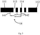
- a peripheral edge of the metal housing has a peripheral frame 11 provided with at least one slot zone 12, the at least one slot zone 12 divides the peripheral frame 11 into at least one segment of a frame body 101, the slot zone 12 is formed by at least three adjacent slots 113 arranged at intervals, and metal parts 114 of the peripheral frame are respectively provided between the at least three adjacent slots.
- the switch 13 includes a first end 131 and a second end 132, the first end 131 is electrically coupled to the frame body 101 divided by the slot zone 12, the second end 132 is electrically coupled to the metal part 114, and the at least one segment of the frame body 101 divided by the at least one slot zone 12 each is an independent antenna.
- the independent antenna refers to the antenna radiator capable of radiating a radio frequency signal of a certain frequency after being configured.
- the independent antenna may be the antenna radiator of a GPS antenna, a Wi-Fi antenna, or an NFC antenna.
- the peripheral frame 11 is provided with four slot zones 12. Every two slot zones 12 form one segment of the frame body 101 serving as the independent antenna therebetween, therefore four segments of frame bodies 101 are formed.
- the frame bodies 101 at least include a first frame body 111 and a second frame body 112.
- the matching circuit 15 is located between the radio frequency circuit 16 and the first frame body 111, and is electrically coupled to the radio frequency circuit 16 and the first frame body 111.
- the matching circuit 15 is configured to match impedance of the antenna, so as to reduce return loss caused by impedance mismatch.
- the number of the slot zones 12 is determined by practical requirements. For example, one, two, or three the slot zones 12 may also be provided.
- the slot zone 12 is formed by at least two slots 113 arranged at intervals, and two adjacent slots 113 have the metal part 114 therebetween. It should be noted that these contents in this paragraph are not intended to describe part of the present invention, but for better understanding of the present invention.
- a case where there are four slots 113 and three metal parts 114 is taken as an example for description.
- the number of the slots 113 or the metal parts 114 is not limited to this, but is determined based on specific design needs.
- three slots 113 may also be provided.
- a width of the slot zone 12 is 1.5 mm to 5.0 mm, a width of each slot 113 within the slot zone 12 is 0.05 mm to 0.3 mm.
- the widths of the slot zone 12 and the slot 113 are determined based on specific design needs and process precision, and/or the slots 113 are arranged at unequal intervals.
- the slots 113 are arranged at equal intervals. In another embodiment, three slots 113 are provided and arranged at equal intervals. The arrangement of the equally spaced slots 113 is easy to process. It should be noted that these contents in this paragraph are not intended to describe part of the present invention, but for better understanding of the present invention.
- the switch 13 includes the first end 131 and the second end 132.
- the first end 131 of the switch 13 is electrically coupled to the first frame body 111
- the second end 132 is electrically coupled to one metal part 114 within the slot zone 12.
- the one metal part 114 is adjacent to the first frame body 111.
- the low-frequency bandwidth of the antenna will vary with the change of the resonant frequency of the antenna.
- the different low-frequency bandwidths can be obtained by means of the closed and open states of the switch, that is, the low-frequency bandwidth is expanded, and the degree of freedom of performance adjustment of the antenna is increased.
- the switch 13 is a single-pole single-throw switch, and the second end 132 of the switch 13 can only be electrically coupled to one metal part 14, so only one low-frequency bandwidth is expanded.
- a switch 14 is a single-pole dual-throw switch, and the switch 14 includes two second ends 142.
- the two second ends 142 of the switch 14 are electrically coupled to two different metal parts 114 correspondingly.
- two low-frequency bandwidths can be expanded by means of different states of the switch 14.
- the switch may be other types of single-pole multi-throw switch, and for example, the switch is a single-pole three-throw switch.
- the switch includes a plurality of second ends, and the plurality of second ends may be electrically coupled to more different metal parts 114 correspondingly.
- the low frequency bandwidth may be further expanded, and the degree of freedom of performance adjustment of the antenna may be further increased.
- an inductance element or a capacitive element is further provided between the switch 13 or 14 and the metal part 14.
- the performance adjustment of the antenna can be further facilitated by providing an inductor or a capacitor.
- the number of the switches 13 or 14 may be other numbers, and for example, two switches 13 or 14 are provided.
- the first frame body 111 is electrically coupled to one or more metal parts 114 within one adjacent slot zone 12 by means of one switch 13 or 14, and the second frame body 112 is electrically coupled to one or more metal parts 114 within another adjacent slot zone 12 by means of the other switch 13 or 14. Therefore, the antenna performance adjustment and expansion for different antennas can be performed by means of the switch.
- the first frame body 111 is a GPS antenna
- the second frame body 112 is a Wi-Fi antenna.
- the remaining two frame bodies divided by the four slot zones 12 may be a Bluetooth antenna, an NFC (Near Field Communication) antenna, or the like.
- the peripheral frame is divided into at least one segment of frame body serving as the independent antenna and the metal part located between the adjacent slots, such that two ends of the switch are electrically coupled to the frame body and the metal part correspondingly.
- the equivalent length of the antenna is changed, and the resonant frequency of the antenna is changed therewith, such that the different low-frequency bandwidths can be obtained.
- the low-frequency bandwidth of the antenna of the electronic device is expanded, and the degree of freedom of performance adjustment of the antenna is increased.
Landscapes
- Engineering & Computer Science (AREA)
- Computer Networks & Wireless Communication (AREA)
- Microelectronics & Electronic Packaging (AREA)
- Support Of Aerials (AREA)
- Variable-Direction Aerials And Aerial Arrays (AREA)
- Details Of Aerials (AREA)
- Telephone Set Structure (AREA)
- Waveguide Aerials (AREA)
Claims (7)
- Antennenbaugruppe, die Folgendes umfasst:ein Metallgehäuse, das einen Peripherierahmen (11) umfasst, der mit mindestens einer Schlitzzone (12) versehen ist, wobei die mindestens eine Schlitzzone (12) den Peripherierahmen (11) in mindestens ein Segment eines Rahmenkörpers (101) teilt, wobei jede der mindestens einen Schlitzzone (12) mindestens drei nebeneinanderliegende Schlitze (113) umfasst, die Metallteile (114) des Peripherierahmens (11) ausbilden, die jeweils zwischen den mindestens drei nebeneinanderliegenden Schlitzen (113) vorgesehen sind; undmindestens einen Schalter (13, 14), wobei der Schalter (13, 14) ein erstes Ende (131, 141) und mindestens ein zweites Ende (132, 142) umfasst,wobei die mindestens drei Schlitze (113) in ungleichen Intervallen angeordnet sind, wobei das erste Ende (131, 141) elektrisch mit dem durch die Schlitzzone (12) geteilten Rahmenkörper (101) gekoppelt ist, das mindestens eine zweite Ende (132, 142) elektrisch mit einem der Metallteile (114) gekoppelt ist und das mindestens eine Segment des durch die mindestens eine Schlitzzone (12) geteilten Rahmenkörpers (101) eine unabhängige Antenne ist, die in der Antennenbaugruppe enthalten ist,dadurch gekennzeichnet, dass der Peripherierahmen (11) mit vier Schlitzzonen (12) versehen ist und jeweils zwei Schlitzzonen ein Segment des Rahmenkörpers (101) ausbilden, so dass vier Rahmenkörper (101) ausgebildet werden;wobei die Rahmenkörper (101) mindestens einen ersten Rahmenkörper (111) und einen zweiten Rahmenkörper (112) umfassen, wobei der erste Rahmenkörper (111) eine GPS-Antenne ist und der zweite Rahmenkörper (112) eine Wi-Fi-Antenne ist;und zwei Schalter (13, 14) vorgesehen sind, wobei der erste Rahmenkörper (111) elektrisch mittels eines der zwei Schalter (13, 14) mit dem einen oder den mehreren Metallteilen (114) innerhalb einer angrenzenden Schlitzzone (12) gekoppelt ist, und der zweite Rahmenkörper elektrisch mittels des anderen der zwei Schalter (13, 14) mit dem einem oder den mehreren Metallteilen (114) innerhalb einer anderen angrenzenden Schlitzzone (12) gekoppelt ist,wobei die Antennenbaugruppe ferner eine Anpassschaltung (15) und eine Hochfrequenzschaltung (16) umfasst, wobei sich die Anpassschaltung (15) zwischen der Hochfrequenzschaltung (16) und dem ersten Rahmenkörper (111) befindet und elektrisch mit der Hochfrequenzschaltung (16) und dem ersten Rahmenkörper (111) gekoppelt ist.
- Antennenbaugruppe nach Anspruch 1, wobei der Schalter (13) ein einpoliger Ein/-Aus-Schalter ist, der Schalter (13) ein zweites Ende (132) umfasst, und das zweite Ende (132) elektrisch mit dem einen der Metallteile (114) innerhalb der Schlitzzone gekoppelt ist.
- Antennenbaugruppe nach Anspruch 1, wobei der Schalter (14) ein einpoliger Mehrfach-Ein/Aus-Schalter ist, wobei der Schalter (14) mehrere zweite Enden (142) umfasst, und die mehreren zweiten Enden (142) jeweils mit unterschiedlichen Metallteilen (114) innerhalb derselben Schlitzzone (12) gekoppelt sind.
- Antennenbaugruppe nach einem der Ansprüche 1 bis 3, wobei die Antennenbaugruppe ferner eine Induktivität oder einen Kondensator, gekoppelt mit dem Schalter (13, 14), umfasst.
- Antennenbaugruppe nach einem der Ansprüche 1 bis 4, wobei eine Breite der Schlitzzone (12) von 1,5 mm bis 5,0 mm beträgt.
- Antennenbaugruppe nach einem der Ansprüche 1 bis 5, wobei eine Breite des Schlitzes (113) von 0,05 mm bis 0,3 mm beträgt.
- Elektronische Vorrichtung (10), die Folgendes umfasst:
eine Antennenbaugruppe nach einem der Ansprüche 1 bis 6.
Applications Claiming Priority (2)
| Application Number | Priority Date | Filing Date | Title |
|---|---|---|---|
| CN201610161288.XA CN105655705B (zh) | 2016-03-18 | 2016-03-18 | 电子装置 |
| PCT/CN2017/077128 WO2017157336A1 (zh) | 2016-03-18 | 2017-03-17 | 金属壳体、壳体天线和电子装置 |
Publications (3)
| Publication Number | Publication Date |
|---|---|
| EP3333976A1 EP3333976A1 (de) | 2018-06-13 |
| EP3333976A4 EP3333976A4 (de) | 2018-10-10 |
| EP3333976B1 true EP3333976B1 (de) | 2020-08-05 |
Family
ID=56494958
Family Applications (1)
| Application Number | Title | Priority Date | Filing Date |
|---|---|---|---|
| EP17765878.8A Not-in-force EP3333976B1 (de) | 2016-03-18 | 2017-03-17 | Metallgehäuse, gehäuseantenne und elektronische vorrichtung |
Country Status (4)
| Country | Link |
|---|---|
| US (2) | US10897079B2 (de) |
| EP (1) | EP3333976B1 (de) |
| CN (1) | CN105655705B (de) |
| WO (1) | WO2017157336A1 (de) |
Families Citing this family (9)
| Publication number | Priority date | Publication date | Assignee | Title |
|---|---|---|---|---|
| WO2017156900A1 (zh) * | 2016-03-18 | 2017-09-21 | 广东欧珀移动通信有限公司 | 金属外壳、天线装置和移动终端 |
| CN105655705B (zh) * | 2016-03-18 | 2017-08-29 | 广东欧珀移动通信有限公司 | 电子装置 |
| CN106025545B (zh) * | 2016-06-29 | 2018-09-04 | 广东欧珀移动通信有限公司 | 天线装置及终端设备 |
| CN108400425B (zh) * | 2017-02-08 | 2020-11-27 | 中兴通讯股份有限公司 | 一种移动终端及其天线 |
| CN107453055B (zh) * | 2017-05-02 | 2021-02-26 | 瑞声科技(新加坡)有限公司 | 天线以及移动终端 |
| CN110556619B (zh) * | 2018-06-01 | 2021-10-19 | 深圳富泰宏精密工业有限公司 | 天线结构及具有该天线结构的无线通信装置 |
| CN109818138B (zh) * | 2019-03-07 | 2023-04-07 | 闻泰通讯股份有限公司 | 天线结构 |
| CN110323541B (zh) * | 2019-06-14 | 2021-07-13 | 青岛海信移动通信技术股份有限公司 | 一种终端 |
| CN113078444B (zh) * | 2020-01-06 | 2024-06-11 | 深圳富泰宏精密工业有限公司 | 天线结构及具有该天线结构的无线通信装置 |
Citations (1)
| Publication number | Priority date | Publication date | Assignee | Title |
|---|---|---|---|---|
| US20120112969A1 (en) * | 2010-11-05 | 2012-05-10 | Ruben Caballero | Antenna system with receiver diversity and tunable matching circuit |
Family Cites Families (25)
| Publication number | Priority date | Publication date | Assignee | Title |
|---|---|---|---|---|
| JPH08242118A (ja) * | 1995-03-06 | 1996-09-17 | Sony Corp | 平面アンテナ、その共振周波数制御方法、及び無線通信装置 |
| US6624789B1 (en) * | 2002-04-11 | 2003-09-23 | Nokia Corporation | Method and system for improving isolation in radio-frequency antennas |
| US8896487B2 (en) | 2009-07-09 | 2014-11-25 | Apple Inc. | Cavity antennas for electronic devices |
| US8610629B2 (en) * | 2010-05-27 | 2013-12-17 | Apple Inc. | Housing structures for optimizing location of emitted radio-frequency signals |
| US9070969B2 (en) * | 2010-07-06 | 2015-06-30 | Apple Inc. | Tunable antenna systems |
| US8791864B2 (en) | 2011-01-11 | 2014-07-29 | Apple Inc. | Antenna structures with electrical connections to device housing members |
| KR101801186B1 (ko) | 2011-02-25 | 2017-11-24 | 엘지전자 주식회사 | 이동 단말기 |
| KR102013588B1 (ko) | 2012-09-19 | 2019-08-23 | 엘지전자 주식회사 | 이동 단말기 |
| TWI617085B (zh) | 2013-05-31 | 2018-03-01 | 群邁通訊股份有限公司 | 天線結構及應用該天線結構的無線通訊裝置 |
| CN103390793A (zh) | 2013-07-29 | 2013-11-13 | 苏州维特比信息技术有限公司 | 一种使用金属框天线的移动终端 |
| CN104681929B (zh) | 2013-11-30 | 2019-05-21 | 深圳富泰宏精密工业有限公司 | 天线结构及具有该天线结构的无线通信装置 |
| CN104953292B (zh) * | 2014-03-25 | 2019-03-08 | 联想(北京)有限公司 | 一种天线及电子设备 |
| CN104584324B (zh) * | 2014-03-28 | 2019-03-26 | 华为终端(东莞)有限公司 | 电子装置金属外壳与天线的整合结构 |
| CN203775569U (zh) | 2014-03-28 | 2014-08-13 | 华为终端有限公司 | 电子装置及其金属壳体 |
| CN104103888B (zh) | 2014-08-06 | 2016-09-21 | 广东欧珀移动通信有限公司 | 一种手机及其天线 |
| KR102226173B1 (ko) | 2014-09-02 | 2021-03-10 | 삼성전자주식회사 | 외부 금속 프레임을 이용한 안테나 및 이를 구비한 전자 장치 |
| WO2016106779A1 (zh) * | 2015-01-04 | 2016-07-07 | 华为技术有限公司 | 手持设备 |
| CN104640391B (zh) * | 2015-02-13 | 2017-11-14 | 广东欧珀移动通信有限公司 | 一种金属外壳、移动终端及制作方法 |
| CN105244599A (zh) * | 2015-10-30 | 2016-01-13 | 维沃移动通信有限公司 | 一种移动终端的天线和移动终端 |
| CN105655704B (zh) | 2016-03-18 | 2018-03-27 | 广东欧珀移动通信有限公司 | 天线装置及移动终端 |
| CN105655705B (zh) * | 2016-03-18 | 2017-08-29 | 广东欧珀移动通信有限公司 | 电子装置 |
| CN205583139U (zh) * | 2016-03-18 | 2016-09-14 | 广东欧珀移动通信有限公司 | 电子装置 |
| CN108039566B (zh) | 2016-03-18 | 2020-01-31 | Oppo广东移动通信有限公司 | 金属终端后盖及终端 |
| WO2017156900A1 (zh) | 2016-03-18 | 2017-09-21 | 广东欧珀移动通信有限公司 | 金属外壳、天线装置和移动终端 |
| CN107834162B (zh) | 2016-03-18 | 2021-08-24 | Oppo广东移动通信有限公司 | 天线装置和移动终端 |
-
2016
- 2016-03-18 CN CN201610161288.XA patent/CN105655705B/zh not_active Expired - Fee Related
-
2017
- 2017-03-17 EP EP17765878.8A patent/EP3333976B1/de not_active Not-in-force
- 2017-03-17 WO PCT/CN2017/077128 patent/WO2017157336A1/zh not_active Ceased
- 2017-03-17 US US15/752,226 patent/US10897079B2/en not_active Expired - Fee Related
-
2018
- 2018-04-30 US US15/966,763 patent/US10122084B2/en active Active
Patent Citations (1)
| Publication number | Priority date | Publication date | Assignee | Title |
|---|---|---|---|---|
| US20120112969A1 (en) * | 2010-11-05 | 2012-05-10 | Ruben Caballero | Antenna system with receiver diversity and tunable matching circuit |
Also Published As
| Publication number | Publication date |
|---|---|
| WO2017157336A1 (zh) | 2017-09-21 |
| US10897079B2 (en) | 2021-01-19 |
| CN105655705A (zh) | 2016-06-08 |
| US20180248260A1 (en) | 2018-08-30 |
| EP3333976A1 (de) | 2018-06-13 |
| US10122084B2 (en) | 2018-11-06 |
| CN105655705B (zh) | 2017-08-29 |
| EP3333976A4 (de) | 2018-10-10 |
| US20190260114A1 (en) | 2019-08-22 |
Similar Documents
| Publication | Publication Date | Title |
|---|---|---|
| US10122084B2 (en) | Electronic device | |
| US10819014B2 (en) | Antenna system and mobile terminal | |
| CN109149086B (zh) | 天线系统及移动终端 | |
| US9660326B2 (en) | Conductive loop antennas | |
| EP3350875B1 (de) | Anpassung von multiantennnenisolierung | |
| EP3252867B1 (de) | Endgerät | |
| US10224626B1 (en) | Co-located active steering antennas configured for band switching, impedance matching and unit selectivity | |
| EP3133695B1 (de) | Antennensystem und antennenmodul mit verminderter interferenz zwischen strahlungsmustern | |
| US10374287B2 (en) | Antenna system with full metal back cover | |
| EP2704253B1 (de) | Mobile Vorrichtung und Antennenstruktur darin | |
| US9980018B2 (en) | Communication device with narrow-ground-clearance antenna element | |
| EP3134940B1 (de) | Schaltbare antenne mit pi-form | |
| EP3220478B1 (de) | Diversitätsantenne | |
| TW202306242A (zh) | 天線結構 | |
| KR102963251B1 (ko) | 용량 결합성 피드 요소를 구비한 멀티피드 안테나 시스템 | |
| US7403161B2 (en) | Multiband antenna in a communication device | |
| CN105530342B (zh) | 天线系统及其移动终端 | |
| EP3529856B1 (de) | Multiresonante antennenstruktur | |
| CN104979634A (zh) | 天线装置及包括天线装置的可穿戴设备 | |
| EP3032644A1 (de) | Dipolantenne | |
| US20170365927A1 (en) | Square shaped multi-slotted 2.45ghz wearable antenna | |
| US11038271B2 (en) | Communication device | |
| CN106785491B (zh) | 一种偶极双频天线和电子产品 | |
| CN205583139U (zh) | 电子装置 | |
| EP3791444B1 (de) | Antennenanordnung für drahtlose vorrichtung |
Legal Events
| Date | Code | Title | Description |
|---|---|---|---|
| STAA | Information on the status of an ep patent application or granted ep patent |
Free format text: STATUS: THE INTERNATIONAL PUBLICATION HAS BEEN MADE |
|
| PUAI | Public reference made under article 153(3) epc to a published international application that has entered the european phase |
Free format text: ORIGINAL CODE: 0009012 |
|
| STAA | Information on the status of an ep patent application or granted ep patent |
Free format text: STATUS: REQUEST FOR EXAMINATION WAS MADE |
|
| 17P | Request for examination filed |
Effective date: 20180306 |
|
| AK | Designated contracting states |
Kind code of ref document: A1 Designated state(s): AL AT BE BG CH CY CZ DE DK EE ES FI FR GB GR HR HU IE IS IT LI LT LU LV MC MK MT NL NO PL PT RO RS SE SI SK SM TR |
|
| AX | Request for extension of the european patent |
Extension state: BA ME |
|
| REG | Reference to a national code |
Ref country code: DE Ref legal event code: R079 Ref document number: 602017021196 Country of ref document: DE Free format text: PREVIOUS MAIN CLASS: H01Q0001440000 Ipc: H01Q0005321000 |
|
| A4 | Supplementary search report drawn up and despatched |
Effective date: 20180910 |
|
| RIC1 | Information provided on ipc code assigned before grant |
Ipc: H01Q 1/24 20060101ALI20180904BHEP Ipc: H01Q 1/44 20060101ALI20180904BHEP Ipc: H01Q 5/321 20150101AFI20180904BHEP |
|
| STAA | Information on the status of an ep patent application or granted ep patent |
Free format text: STATUS: EXAMINATION IS IN PROGRESS |
|
| 17Q | First examination report despatched |
Effective date: 20190130 |
|
| DAV | Request for validation of the european patent (deleted) | ||
| DAX | Request for extension of the european patent (deleted) | ||
| RAP1 | Party data changed (applicant data changed or rights of an application transferred) |
Owner name: GUANGDONG OPPO MOBILE TELECOMMUNICATIONS CORP., LT |
|
| GRAP | Despatch of communication of intention to grant a patent |
Free format text: ORIGINAL CODE: EPIDOSNIGR1 |
|
| STAA | Information on the status of an ep patent application or granted ep patent |
Free format text: STATUS: GRANT OF PATENT IS INTENDED |
|
| INTG | Intention to grant announced |
Effective date: 20200313 |
|
| GRAS | Grant fee paid |
Free format text: ORIGINAL CODE: EPIDOSNIGR3 |
|
| GRAA | (expected) grant |
Free format text: ORIGINAL CODE: 0009210 |
|
| STAA | Information on the status of an ep patent application or granted ep patent |
Free format text: STATUS: THE PATENT HAS BEEN GRANTED |
|
| AK | Designated contracting states |
Kind code of ref document: B1 Designated state(s): AL AT BE BG CH CY CZ DE DK EE ES FI FR GB GR HR HU IE IS IT LI LT LU LV MC MK MT NL NO PL PT RO RS SE SI SK SM TR |
|
| REG | Reference to a national code |
Ref country code: GB Ref legal event code: FG4D |
|
| REG | Reference to a national code |
Ref country code: CH Ref legal event code: EP |
|
| REG | Reference to a national code |
Ref country code: AT Ref legal event code: REF Ref document number: 1300022 Country of ref document: AT Kind code of ref document: T Effective date: 20200815 |
|
| REG | Reference to a national code |
Ref country code: DE Ref legal event code: R096 Ref document number: 602017021196 Country of ref document: DE |
|
| REG | Reference to a national code |
Ref country code: IE Ref legal event code: FG4D |
|
| REG | Reference to a national code |
Ref country code: LT Ref legal event code: MG4D |
|
| REG | Reference to a national code |
Ref country code: NL Ref legal event code: MP Effective date: 20200805 |
|
| REG | Reference to a national code |
Ref country code: AT Ref legal event code: MK05 Ref document number: 1300022 Country of ref document: AT Kind code of ref document: T Effective date: 20200805 |
|
| PG25 | Lapsed in a contracting state [announced via postgrant information from national office to epo] |
Ref country code: PT Free format text: LAPSE BECAUSE OF FAILURE TO SUBMIT A TRANSLATION OF THE DESCRIPTION OR TO PAY THE FEE WITHIN THE PRESCRIBED TIME-LIMIT Effective date: 20201207 Ref country code: ES Free format text: LAPSE BECAUSE OF FAILURE TO SUBMIT A TRANSLATION OF THE DESCRIPTION OR TO PAY THE FEE WITHIN THE PRESCRIBED TIME-LIMIT Effective date: 20200805 Ref country code: LT Free format text: LAPSE BECAUSE OF FAILURE TO SUBMIT A TRANSLATION OF THE DESCRIPTION OR TO PAY THE FEE WITHIN THE PRESCRIBED TIME-LIMIT Effective date: 20200805 Ref country code: AT Free format text: LAPSE BECAUSE OF FAILURE TO SUBMIT A TRANSLATION OF THE DESCRIPTION OR TO PAY THE FEE WITHIN THE PRESCRIBED TIME-LIMIT Effective date: 20200805 Ref country code: BG Free format text: LAPSE BECAUSE OF FAILURE TO SUBMIT A TRANSLATION OF THE DESCRIPTION OR TO PAY THE FEE WITHIN THE PRESCRIBED TIME-LIMIT Effective date: 20201105 Ref country code: SE Free format text: LAPSE BECAUSE OF FAILURE TO SUBMIT A TRANSLATION OF THE DESCRIPTION OR TO PAY THE FEE WITHIN THE PRESCRIBED TIME-LIMIT Effective date: 20200805 Ref country code: HR Free format text: LAPSE BECAUSE OF FAILURE TO SUBMIT A TRANSLATION OF THE DESCRIPTION OR TO PAY THE FEE WITHIN THE PRESCRIBED TIME-LIMIT Effective date: 20200805 Ref country code: FI Free format text: LAPSE BECAUSE OF FAILURE TO SUBMIT A TRANSLATION OF THE DESCRIPTION OR TO PAY THE FEE WITHIN THE PRESCRIBED TIME-LIMIT Effective date: 20200805 Ref country code: NO Free format text: LAPSE BECAUSE OF FAILURE TO SUBMIT A TRANSLATION OF THE DESCRIPTION OR TO PAY THE FEE WITHIN THE PRESCRIBED TIME-LIMIT Effective date: 20201105 Ref country code: GR Free format text: LAPSE BECAUSE OF FAILURE TO SUBMIT A TRANSLATION OF THE DESCRIPTION OR TO PAY THE FEE WITHIN THE PRESCRIBED TIME-LIMIT Effective date: 20201106 |
|
| PG25 | Lapsed in a contracting state [announced via postgrant information from national office to epo] |
Ref country code: RS Free format text: LAPSE BECAUSE OF FAILURE TO SUBMIT A TRANSLATION OF THE DESCRIPTION OR TO PAY THE FEE WITHIN THE PRESCRIBED TIME-LIMIT Effective date: 20200805 Ref country code: LV Free format text: LAPSE BECAUSE OF FAILURE TO SUBMIT A TRANSLATION OF THE DESCRIPTION OR TO PAY THE FEE WITHIN THE PRESCRIBED TIME-LIMIT Effective date: 20200805 Ref country code: NL Free format text: LAPSE BECAUSE OF FAILURE TO SUBMIT A TRANSLATION OF THE DESCRIPTION OR TO PAY THE FEE WITHIN THE PRESCRIBED TIME-LIMIT Effective date: 20200805 Ref country code: PL Free format text: LAPSE BECAUSE OF FAILURE TO SUBMIT A TRANSLATION OF THE DESCRIPTION OR TO PAY THE FEE WITHIN THE PRESCRIBED TIME-LIMIT Effective date: 20200805 Ref country code: IS Free format text: LAPSE BECAUSE OF FAILURE TO SUBMIT A TRANSLATION OF THE DESCRIPTION OR TO PAY THE FEE WITHIN THE PRESCRIBED TIME-LIMIT Effective date: 20201205 |
|
| PG25 | Lapsed in a contracting state [announced via postgrant information from national office to epo] |
Ref country code: EE Free format text: LAPSE BECAUSE OF FAILURE TO SUBMIT A TRANSLATION OF THE DESCRIPTION OR TO PAY THE FEE WITHIN THE PRESCRIBED TIME-LIMIT Effective date: 20200805 Ref country code: SM Free format text: LAPSE BECAUSE OF FAILURE TO SUBMIT A TRANSLATION OF THE DESCRIPTION OR TO PAY THE FEE WITHIN THE PRESCRIBED TIME-LIMIT Effective date: 20200805 Ref country code: RO Free format text: LAPSE BECAUSE OF FAILURE TO SUBMIT A TRANSLATION OF THE DESCRIPTION OR TO PAY THE FEE WITHIN THE PRESCRIBED TIME-LIMIT Effective date: 20200805 Ref country code: CZ Free format text: LAPSE BECAUSE OF FAILURE TO SUBMIT A TRANSLATION OF THE DESCRIPTION OR TO PAY THE FEE WITHIN THE PRESCRIBED TIME-LIMIT Effective date: 20200805 Ref country code: DK Free format text: LAPSE BECAUSE OF FAILURE TO SUBMIT A TRANSLATION OF THE DESCRIPTION OR TO PAY THE FEE WITHIN THE PRESCRIBED TIME-LIMIT Effective date: 20200805 |
|
| REG | Reference to a national code |
Ref country code: DE Ref legal event code: R097 Ref document number: 602017021196 Country of ref document: DE |
|
| PG25 | Lapsed in a contracting state [announced via postgrant information from national office to epo] |
Ref country code: AL Free format text: LAPSE BECAUSE OF FAILURE TO SUBMIT A TRANSLATION OF THE DESCRIPTION OR TO PAY THE FEE WITHIN THE PRESCRIBED TIME-LIMIT Effective date: 20200805 |
|
| PLBE | No opposition filed within time limit |
Free format text: ORIGINAL CODE: 0009261 |
|
| STAA | Information on the status of an ep patent application or granted ep patent |
Free format text: STATUS: NO OPPOSITION FILED WITHIN TIME LIMIT |
|
| PG25 | Lapsed in a contracting state [announced via postgrant information from national office to epo] |
Ref country code: SK Free format text: LAPSE BECAUSE OF FAILURE TO SUBMIT A TRANSLATION OF THE DESCRIPTION OR TO PAY THE FEE WITHIN THE PRESCRIBED TIME-LIMIT Effective date: 20200805 |
|
| 26N | No opposition filed |
Effective date: 20210507 |
|
| PG25 | Lapsed in a contracting state [announced via postgrant information from national office to epo] |
Ref country code: IT Free format text: LAPSE BECAUSE OF FAILURE TO SUBMIT A TRANSLATION OF THE DESCRIPTION OR TO PAY THE FEE WITHIN THE PRESCRIBED TIME-LIMIT Effective date: 20200805 |
|
| PG25 | Lapsed in a contracting state [announced via postgrant information from national office to epo] |
Ref country code: SI Free format text: LAPSE BECAUSE OF FAILURE TO SUBMIT A TRANSLATION OF THE DESCRIPTION OR TO PAY THE FEE WITHIN THE PRESCRIBED TIME-LIMIT Effective date: 20200805 |
|
| PG25 | Lapsed in a contracting state [announced via postgrant information from national office to epo] |
Ref country code: MC Free format text: LAPSE BECAUSE OF FAILURE TO SUBMIT A TRANSLATION OF THE DESCRIPTION OR TO PAY THE FEE WITHIN THE PRESCRIBED TIME-LIMIT Effective date: 20200805 |
|
| REG | Reference to a national code |
Ref country code: CH Ref legal event code: PL |
|
| REG | Reference to a national code |
Ref country code: BE Ref legal event code: MM Effective date: 20210331 |
|
| PG25 | Lapsed in a contracting state [announced via postgrant information from national office to epo] |
Ref country code: LI Free format text: LAPSE BECAUSE OF NON-PAYMENT OF DUE FEES Effective date: 20210331 Ref country code: LU Free format text: LAPSE BECAUSE OF NON-PAYMENT OF DUE FEES Effective date: 20210317 Ref country code: CH Free format text: LAPSE BECAUSE OF NON-PAYMENT OF DUE FEES Effective date: 20210331 Ref country code: IE Free format text: LAPSE BECAUSE OF NON-PAYMENT OF DUE FEES Effective date: 20210317 |
|
| PG25 | Lapsed in a contracting state [announced via postgrant information from national office to epo] |
Ref country code: BE Free format text: LAPSE BECAUSE OF NON-PAYMENT OF DUE FEES Effective date: 20210331 |
|
| PGFP | Annual fee paid to national office [announced via postgrant information from national office to epo] |
Ref country code: FR Payment date: 20221219 Year of fee payment: 7 |
|
| PGFP | Annual fee paid to national office [announced via postgrant information from national office to epo] |
Ref country code: GB Payment date: 20230110 Year of fee payment: 7 Ref country code: DE Payment date: 20221213 Year of fee payment: 7 |
|
| P01 | Opt-out of the competence of the unified patent court (upc) registered |
Effective date: 20230412 |
|
| PG25 | Lapsed in a contracting state [announced via postgrant information from national office to epo] |
Ref country code: CY Free format text: LAPSE BECAUSE OF FAILURE TO SUBMIT A TRANSLATION OF THE DESCRIPTION OR TO PAY THE FEE WITHIN THE PRESCRIBED TIME-LIMIT Effective date: 20200805 |
|
| PG25 | Lapsed in a contracting state [announced via postgrant information from national office to epo] |
Ref country code: HU Free format text: LAPSE BECAUSE OF FAILURE TO SUBMIT A TRANSLATION OF THE DESCRIPTION OR TO PAY THE FEE WITHIN THE PRESCRIBED TIME-LIMIT; INVALID AB INITIO Effective date: 20170317 |
|
| PG25 | Lapsed in a contracting state [announced via postgrant information from national office to epo] |
Ref country code: MK Free format text: LAPSE BECAUSE OF FAILURE TO SUBMIT A TRANSLATION OF THE DESCRIPTION OR TO PAY THE FEE WITHIN THE PRESCRIBED TIME-LIMIT Effective date: 20200805 |
|
| PG25 | Lapsed in a contracting state [announced via postgrant information from national office to epo] |
Ref country code: TR Free format text: LAPSE BECAUSE OF FAILURE TO SUBMIT A TRANSLATION OF THE DESCRIPTION OR TO PAY THE FEE WITHIN THE PRESCRIBED TIME-LIMIT Effective date: 20200805 |
|
| PG25 | Lapsed in a contracting state [announced via postgrant information from national office to epo] |
Ref country code: MT Free format text: LAPSE BECAUSE OF FAILURE TO SUBMIT A TRANSLATION OF THE DESCRIPTION OR TO PAY THE FEE WITHIN THE PRESCRIBED TIME-LIMIT Effective date: 20200805 |
|
| REG | Reference to a national code |
Ref country code: DE Ref legal event code: R119 Ref document number: 602017021196 Country of ref document: DE |
|
| GBPC | Gb: european patent ceased through non-payment of renewal fee |
Effective date: 20240317 |
|
| PG25 | Lapsed in a contracting state [announced via postgrant information from national office to epo] |
Ref country code: DE Free format text: LAPSE BECAUSE OF NON-PAYMENT OF DUE FEES Effective date: 20241001 |
|
| PG25 | Lapsed in a contracting state [announced via postgrant information from national office to epo] |
Ref country code: GB Free format text: LAPSE BECAUSE OF NON-PAYMENT OF DUE FEES Effective date: 20240317 |
|
| PG25 | Lapsed in a contracting state [announced via postgrant information from national office to epo] |
Ref country code: FR Free format text: LAPSE BECAUSE OF NON-PAYMENT OF DUE FEES Effective date: 20240331 |
|
| PG25 | Lapsed in a contracting state [announced via postgrant information from national office to epo] |
Ref country code: GB Free format text: LAPSE BECAUSE OF NON-PAYMENT OF DUE FEES Effective date: 20240317 Ref country code: FR Free format text: LAPSE BECAUSE OF NON-PAYMENT OF DUE FEES Effective date: 20240331 Ref country code: DE Free format text: LAPSE BECAUSE OF NON-PAYMENT OF DUE FEES Effective date: 20241001 |