EP3333855B1 - Systems and methods for nuclear reactor dry tube assembly removal and installation - Google Patents
Systems and methods for nuclear reactor dry tube assembly removal and installation Download PDFInfo
- Publication number
- EP3333855B1 EP3333855B1 EP17206012.1A EP17206012A EP3333855B1 EP 3333855 B1 EP3333855 B1 EP 3333855B1 EP 17206012 A EP17206012 A EP 17206012A EP 3333855 B1 EP3333855 B1 EP 3333855B1
- Authority
- EP
- European Patent Office
- Prior art keywords
- dry tube
- tool
- top guide
- tube
- dry
- Prior art date
- Legal status (The legal status is an assumption and is not a legal conclusion. Google has not performed a legal analysis and makes no representation as to the accuracy of the status listed.)
- Active
Links
- 238000000034 method Methods 0.000 title claims description 22
- 238000009434 installation Methods 0.000 title description 6
- 239000000446 fuel Substances 0.000 claims description 27
- 230000000712 assembly Effects 0.000 claims description 13
- 238000000429 assembly Methods 0.000 claims description 13
- 239000002826 coolant Substances 0.000 claims description 4
- 230000000881 depressing effect Effects 0.000 claims description 3
- 230000008602 contraction Effects 0.000 description 2
- 230000004907 flux Effects 0.000 description 2
- 238000003780 insertion Methods 0.000 description 2
- 230000037431 insertion Effects 0.000 description 2
- 230000002452 interceptive effect Effects 0.000 description 2
- 239000000463 material Substances 0.000 description 2
- 230000002285 radioactive effect Effects 0.000 description 2
- 206010000060 Abdominal distension Diseases 0.000 description 1
- 229910000990 Ni alloy Inorganic materials 0.000 description 1
- 229910001093 Zr alloy Inorganic materials 0.000 description 1
- 230000000903 blocking effect Effects 0.000 description 1
- 238000009835 boiling Methods 0.000 description 1
- 238000010276 construction Methods 0.000 description 1
- 239000012530 fluid Substances 0.000 description 1
- 230000003116 impacting effect Effects 0.000 description 1
- 229910001055 inconels 600 Inorganic materials 0.000 description 1
- 238000012423 maintenance Methods 0.000 description 1
- 230000014759 maintenance of location Effects 0.000 description 1
- 238000002844 melting Methods 0.000 description 1
- 230000008018 melting Effects 0.000 description 1
- 239000003758 nuclear fuel Substances 0.000 description 1
- 230000000704 physical effect Effects 0.000 description 1
- 239000012858 resilient material Substances 0.000 description 1
- 238000004904 shortening Methods 0.000 description 1
- 229910001220 stainless steel Inorganic materials 0.000 description 1
- XLYOFNOQVPJJNP-UHFFFAOYSA-N water Substances O XLYOFNOQVPJJNP-UHFFFAOYSA-N 0.000 description 1
Images
Classifications
-
- B—PERFORMING OPERATIONS; TRANSPORTING
- B23—MACHINE TOOLS; METAL-WORKING NOT OTHERWISE PROVIDED FOR
- B23P—METAL-WORKING NOT OTHERWISE PROVIDED FOR; COMBINED OPERATIONS; UNIVERSAL MACHINE TOOLS
- B23P19/00—Machines for simply fitting together or separating metal parts or objects, or metal and non-metal parts, whether or not involving some deformation; Tools or devices therefor so far as not provided for in other classes
- B23P19/04—Machines for simply fitting together or separating metal parts or objects, or metal and non-metal parts, whether or not involving some deformation; Tools or devices therefor so far as not provided for in other classes for assembling or disassembling parts
-
- G—PHYSICS
- G21—NUCLEAR PHYSICS; NUCLEAR ENGINEERING
- G21C—NUCLEAR REACTORS
- G21C17/00—Monitoring; Testing ; Maintaining
- G21C17/017—Inspection or maintenance of pipe-lines or tubes in nuclear installations
-
- G—PHYSICS
- G21—NUCLEAR PHYSICS; NUCLEAR ENGINEERING
- G21C—NUCLEAR REACTORS
- G21C19/00—Arrangements for treating, for handling, or for facilitating the handling of, fuel or other materials which are used within the reactor, e.g. within its pressure vessel
- G21C19/20—Arrangements for introducing objects into the pressure vessel; Arrangements for handling objects within the pressure vessel; Arrangements for removing objects from the pressure vessel
-
- G—PHYSICS
- G21—NUCLEAR PHYSICS; NUCLEAR ENGINEERING
- G21C—NUCLEAR REACTORS
- G21C1/00—Reactor types
- G21C1/04—Thermal reactors ; Epithermal reactors
- G21C1/06—Heterogeneous reactors, i.e. in which fuel and moderator are separated
- G21C1/08—Heterogeneous reactors, i.e. in which fuel and moderator are separated moderator being highly pressurised, e.g. boiling water reactor, integral super-heat reactor, pressurised water reactor
- G21C1/084—Boiling water reactors
-
- G—PHYSICS
- G21—NUCLEAR PHYSICS; NUCLEAR ENGINEERING
- G21C—NUCLEAR REACTORS
- G21C13/00—Pressure vessels; Containment vessels; Containment in general
- G21C13/02—Details
-
- G—PHYSICS
- G21—NUCLEAR PHYSICS; NUCLEAR ENGINEERING
- G21C—NUCLEAR REACTORS
- G21C19/00—Arrangements for treating, for handling, or for facilitating the handling of, fuel or other materials which are used within the reactor, e.g. within its pressure vessel
- G21C19/20—Arrangements for introducing objects into the pressure vessel; Arrangements for handling objects within the pressure vessel; Arrangements for removing objects from the pressure vessel
- G21C19/207—Assembling, maintenance or repair of reactor components
-
- Y—GENERAL TAGGING OF NEW TECHNOLOGICAL DEVELOPMENTS; GENERAL TAGGING OF CROSS-SECTIONAL TECHNOLOGIES SPANNING OVER SEVERAL SECTIONS OF THE IPC; TECHNICAL SUBJECTS COVERED BY FORMER USPC CROSS-REFERENCE ART COLLECTIONS [XRACs] AND DIGESTS
- Y02—TECHNOLOGIES OR APPLICATIONS FOR MITIGATION OR ADAPTATION AGAINST CLIMATE CHANGE
- Y02E—REDUCTION OF GREENHOUSE GAS [GHG] EMISSIONS, RELATED TO ENERGY GENERATION, TRANSMISSION OR DISTRIBUTION
- Y02E30/00—Energy generation of nuclear origin
- Y02E30/30—Nuclear fission reactors
Definitions
- instrumentation tubes may be wholly sealed structures for placement in a nuclear reactor or may be permanent structures opening at an end of the reactor to permit insertion of instrumentation and other devices without interacting with the reactor internals or causing loss of coolant.
- a dry tube which is typically a hollow, sealed tube placed in a core or other location in a reactor pressure vessel and can be fully removed from the same.
- the dry tube can house sensors and other instruments that are retrievable during a maintenance period for analysis and replacement.
- dry tubes reside in fixed internal locations and are secured to in-vessel structures so as to prevent their movement or interference with coolant flow and other reactor operations.
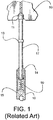
- FIG. 1 is cross-sectional schematic view of a top portion of a related art dry tube 10 as installed in top plate 50 in a nuclear reactor pressure vessel.
- Dry tube 10 conventionally includes a biased plunger 17 that forcibly seats into top plate 50 via an end spur or knob 11.
- a spring 16 or other biasing element in plunger guide 14 may vertically drive plunger 17 into top plate 50.
- Plunger guide 14 and spring 16 can join to a top joint 15 of dry tube 10 that serves as a base for spring 16 and prevents further vertical movement of plunger 17 in guide tube 14.
- a ledge or boss 13 on plunger 17 typically aids with seating and determining vertical distention of plunger 17.
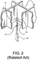
- dry tube 10 can seat up into a recess 51 of top plate 50 at an intersection of grid points of top plate 50.
- Top plate 50 typically serves as an alignment and support structure above the nuclear fuel in a reactor core, and positions of an intersection of grids in top plate 50 are usually otherwise unoccupied.
- An opposite end of dry tube 10 (not shown) may seat into a holder, lower plenum, or other core structure vertically below top plate 50 and recess 51. Under the force of plunger 17, dry tube 10 is thus vertically secured into recess 51 of top plate 50 in a nuclear reactor vessel.
- JPS5689998U relates to an apparatus for removing a neutron flux monitor from a nuclear reactor.
- JP2005010117A relates to a removing device and method for a neutron flux monitor in a nuclear reactor.
- JPH11133179A relates to an intra-furnace instrumentation tube detaching device.
- JPH0527086A relates to a handling device for a neutron instrumentation pipe.
- the present invention provides a tool system and a method, as defined in the appended claims.
- Examples include tool systems used in removal, installation, and/or movement of dry tubes in reactors without complete removal of fuel adjacent to the tubes.
- Examples include a body that fits into a top guide opening to secure next to a dry tube of interest and a retainer that can manipulate the dry tube for insertion, removal, positioning, etc.
- Example tools may include retainers such as forks, hooks, clamps, lassos, etc. for the retainer that secures to the dry tube, and such retainers may occupy and extend diagonally in a quadrant about a fuel assembly to avoid any other remaining fuel assemblies adjacent to the dry tube.
- the retainer may be moveable so as to vertically push or pull a dry tube or plunger in the same to release or secure the dry tube to a core structure such as a holder and/or top guide.
- the retainer may also move horizontally so as to clear or insert a dry tube from or for such vertical movement.
- Example methods include installing and/or removing dry tubes by removing only a subset of directly adjacent fuel assemblies next to the dry tube.
- An example removal tool may then be installed next to the dry tube without interfering with the remaining assemblies.
- a retainer can be operated from the tool to grasp and manipulate the dry tube so that the tool and the attached dry tube can be moved together in the reactor.
- dry tube is defined as a body shaped and sized to fit inside of a nuclear reactor with no aperture or opening outside of the reactor.
- the body includes a heterogeneous interior shaped to house differing structures, such as an internal cavity housing sensors.
- the “dry tube” is nondestructively removable and securable within the reactor by itself, being fixedly attachable to and independently removable from other reactor structures such as fuel, top guides, core plates, instrumentation tubes, shrouds, vessel walls, etc.
- dry tube includes existing dry tubes in commercial nuclear power reactors used to house instrumentation and sensors in nuclear cores and elsewhere.
- FIG. 3 is a perspective illustration of example embodiment dry tube removal tool 100.
- example embodiment dry tube removal tool 100 is a generally vertically elongated structure for submersion in a nuclear reactor.
- Tool 100 may include a handling and connection post 110 configured to connect to a bridge or crane operating above the nuclear reactor, likely flooded during refueling. For example, tool 100 may be lowered vertically from a crane connected to connection post 110 to a desired vertical level within a reactor.
- the dry tube removal tool 100 is shaped to fit in a single quadrant of an opening in a top guide 50.
- Body 120 of tool 100 extends in a vertical direction with a transverse cross-section substantially shaped to top guide 50. In this way, body 120 of tool 100 may be vertically lowered into an opening of top guide 50 and pass along the same without interference.
- body 120 may be largely rectilinear as well with a chamfered front to match top guide 50. In this way, tool 100 may occupy only a single quadrant about dry tube 10 yet fit close to dry tube 10 for handling and removal of the same.
- one or more wings 115 extend from body 120 to secure and position tool 100 with respect to top guide 50. Wings 115 may be sufficiently separated from body 120 so as to permit a top guide portion to seat between wing 115 and body 120 securely. The secure seating may permit only limited vertical movement, holding body 120 relatively flush against and at constant position with the top guide. As shown in FIG. 3 , two wings 115 may extend from body 120 at roughly 90-degree angles from each other in order to seat around opposite sides of an opening in top guide 50, for example. Because example embodiment tool 100 may secure to top guide 50 in only a quarter of an intersection above dry tube 10, a fuel assembly may remain in a diagonal position adjacent to dry tube 10 without interfering with tool 100.
- the tool 100 includes a retainer that structurally secures to dry tube 10 in a removable fashion for moving dry tube 10 in several different directions to achieve removal and/or installation of dry tube 10.
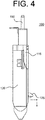
- a grasping fork 125 may be positioned relatively lower from wing 115 and/or top guide 50 when tool 100 is installed on top guide 50.
- grasping fork 125 may be several inches or feet lower toward a bottom of body 120 in order to coincide with a washer, grommet, or boss 13 ( FIG. 1 ) of dry tube 10 or a plunger 17 of dry tube 10.
- grasping fork 125 is moveable outward in a transverse direction and downward in a vertical direction.
- Grasping fork 125 may move outward, transversely from body 120 to securely grasp a dry tube positioned adjacent to tool 100 installed on a top guide.
- grasping fork 125 may include a biasing element or spring that causes its prongs to surround the dry tube and secure to the same.
- grasping fork may mechanically expand around and then clamp onto a dry tube. Grasping fork 125 may then move vertically downward to compress a plunger of the dry tube and remove the same from a top guide.
- grasping fork 125 may seat onto plunger 17 and/or boss 13 and compress the same down into plunger guide 14 ( FIG. 1 ) to remove the dry tube from the top guide.
- Grasping fork 125 may then be transversely withdrawn with the dry tube and/or tool 100 may be vertically lifted off the top guide, such as by a lifting crane, with the dry tube to remove the dry tube from the core.
- example embodiment tool 100 can be secured in a single quadrant about a grid intersection in top guide 50, with grasping fork 125 extending and retrieving dry tube 10 out of top guide 50 from that single quadrant, other adjacent fuel assemblies may be left in a core during dry tube removal.
- a fuel assembly diagonal from tool 100 about dry tube 10 may be left in a core without impacting tool 100 for removal of dry tube 10.
- fewer fuel moves and offloading may be required prior to dry tube removal and replacement, overall shortening the process and allowing fresh detectors and sensors in replaced dry tubes without as much initial fuel movement.
- Grasping fork 125 or another retainer may be powered in a variety of ways.
- grasping fork 125 may be driven by a local motor and battery configured to move the same relative to body 120.
- grasping fork 125 may be driven by a local pneumatic air source stored in body 120.
- grasping fork 125 may be powered remotely, such as through an electrical or pneumatic line extending from an operating bridge above the reactor, potentially on a same line connected to connection post 110.
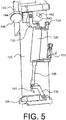
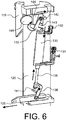
- FIGS. 5 and 6 are illustrations of an example embodiment system for operating and powering grasping fork 125 or another engagement device.
- a local power source may be a pneumatic tube 130 secured within body 120.
- Pneumatic tube 130 may be remotely controlled, such as through wireless signals instructing a receiver and transducers to actuate tube 130, or through pneumatic lines 131 and 132 running up to operators working above on a bridge or crane.
- one pneumatic line 131 may be an actuation line
- another pneumatic line 132 may be a relief line.
- pneumatic tube 130 may actuate with appropriate force, such as by expanding or contracting expansion rod 135.
- pneumatic tube 130 is connected at opposite ends to two actuation arms.
- a roller actuation arm 133 is rotatably coupled with pneumatic tube 130.
- Roller actuation arm 133 is further coupled with a slide block 144 and biased roller 145 or other blocking structure.
- Roller actuation arm 133 may slidably engage with block 144 that is on a track or guide so as to move in a transverse direction as roller actuation arm 133 rotates.
- Biased roller 145 may be rigidly secured to slide block 144 and/or biased against slide block 144 with a spring or other fastener so that roller 145 moves transversely with slide block 144.
- Biased roller 145 may be secured to block 144 with a degree of freedom that permits rotation of roller 145, such as through an axel.
- Forward stop 143 and backward stop 142 may keep slide block 144 and roller actuation arm 133 within desired transverse positions or from under- or over-extending.
- Biased roller 145 may be positioned vertically below a top of wing 115 while extending transversely outward with wing 115. In this way, the roller 145 may rest on a top of top guide 50 ( FIG. 3 ) and block further vertical movement of an example embodiment tool when extended.
- biased roller 145 may be positioned below a top of wing 115 a distance equal to a distance of depression required to remove a dry tube from the top guide, such as a distance equal to a length of knob 11 ( FIG. 1 ) that must be traversed in order to remove the same from top guide 50.
- Biased roller 145 may support an example embodiment tool on a top guide, while an engagement structure, such as grasping fork 125, may be positioned at a level of boss 13 of tube 10. ( FIGS. 1-2 ). In this way, grasping fork 125 may be initially held at a vertical position to mate with boss 13 by virtue of the positioning created by biased roller 145 seated on a top guide.
- an engagement actuation arm 136 is rotatably coupled with pneumatic tube 130, such as through an expansion rod 135.
- Actuation arm 136 may oppositely couple with retention fork 125, which, much like block 144, can be driven transversely upon rotation of engagement actuation arm 136.
- a stop 141 may prevent over-rotation of engagement arm 136, allowing fork 125 to extend only a desired distance, such as the distance to a dry tube to which fork 125 mates.
- biased roller 145 When pneumatic cylinder 130 is driven to expand, such as through appropriate actuation of lines 132 and/or 131, as shown in FIG. 5 , biased roller 145 may be in an extended transverse position, while grasping fork 125 is withdrawn. When pneumatic cylinder 130 is driven to contract, biased roller 145 may roll back as shown in FIG. 6 because roller actuation arm 133 is rotated clockwise by contraction of cylinder 130. Similarly, grasping fork 125 may be driven outward as shown in FIG. 6 because engagement actuation arm 136 is also driven clockwise, such as through contraction of expansion rod 135 into cylinder 130.
- grasping fork 125 may engage with a dry tube transversely and then depress the dry tube vertically through movement of an example embodiment system for operating and powering grasping fork 125.
- repeating or reversing the expansion of cylinder 130 may permit transverse withdrawal and/or installation of a dry tube engaged with retaining fork 125.
- Example embodiment dry tube removal tool 100 may be fabricated of resilient materials that are compatible with a nuclear reactor environment without substantially changing in physical properties, such as becoming substantially radioactive, melting, brittling, or retaining/adsorbing radioactive particulates.
- resilient materials including austenitic stainless steels 304 or 316, XM-19, zirconium alloys, nickel alloys, Alloy 600, etc. may be chosen for any element of components of example embodiment tool 100.
- Joining structures and directly-touching elements may be chosen of different and compatible materials to prevent fouling.
- Example methods may use example embodiment tools to manipulate dry tubes in nuclear reactors without needing to remove all fuel assemblies adjacent to any dry tube.
- an example embodiment tool 100 shown in FIGS. 3 and 4 , may be lowered from an operating bridge via a cable, handling pole, or crane into a flooded reactor, such that the tool is completely submerged and descends to an open position in the top guide. While some fuel may have been removed prior to introduction of the tool, the dry tube of interest need not be completely surrounded by open space. For example, an assembly diagonal and directly adjacent from the dry tube need not be removed. The tool may be seated through a grid in the top guide diagonal from the remaining fuel assembly, such as via wings seating on the sides of the top guide.
- the moveable retainer may extend from the tool to engage the dry tube in example methods. If the dry tube is like dry tube 10 in FIGS. 1 & 2 , the retainer may depress a plunger or other release to remove the dry tube from its location in the core. The tool and dry tube secured to the tool by the retainer may be moved in and/or removed from the reactor for desired placement or disposal.
- example methods may be reversed and a new dry tube or replacement dry tube may be attached to example embodiment tools and submerged to their core position without removing all adjacent fuel.
- a new dry tube or replacement dry tube may be attached to example embodiment tools and submerged to their core position without removing all adjacent fuel.
- the tube By lowering the dry tube into its holder, depressing any plunger, and transversely inserting the tube into its top guide position, the tube may be installed with example embodiments.
- an example embodiment system for operating and powering the tool with a pneumatic cylinder can be used for combined transverse and vertical movement to achieve desired depression and positioning for installation and removal.
Description
- Commercial nuclear reactors, particularly boiling water reactors, often use several different types of instrumentation tubes in their reactor pressure vessels to monitor in-vessel and reactor core conditions. Such instrumentation tubes may be wholly sealed structures for placement in a nuclear reactor or may be permanent structures opening at an end of the reactor to permit insertion of instrumentation and other devices without interacting with the reactor internals or causing loss of coolant. One known type of instrumentation tube is a dry tube, which is typically a hollow, sealed tube placed in a core or other location in a reactor pressure vessel and can be fully removed from the same. The dry tube can house sensors and other instruments that are retrievable during a maintenance period for analysis and replacement. Typically, such dry tubes reside in fixed internal locations and are secured to in-vessel structures so as to prevent their movement or interference with coolant flow and other reactor operations.
-
FIG. 1 is cross-sectional schematic view of a top portion of a related artdry tube 10 as installed intop plate 50 in a nuclear reactor pressure vessel.Dry tube 10 conventionally includes abiased plunger 17 that forcibly seats intotop plate 50 via an end spur orknob 11. For example, aspring 16 or other biasing element inplunger guide 14 may vertically driveplunger 17 intotop plate 50.Plunger guide 14 andspring 16 can join to atop joint 15 ofdry tube 10 that serves as a base forspring 16 and prevents further vertical movement ofplunger 17 inguide tube 14. A ledge orboss 13 onplunger 17 typically aids with seating and determining vertical distention ofplunger 17. - As seen in
FIG. 2 ,dry tube 10 can seat up into arecess 51 oftop plate 50 at an intersection of grid points oftop plate 50.Top plate 50 typically serves as an alignment and support structure above the nuclear fuel in a reactor core, and positions of an intersection of grids intop plate 50 are usually otherwise unoccupied. An opposite end of dry tube 10 (not shown) may seat into a holder, lower plenum, or other core structure vertically belowtop plate 50 and recess 51. Under the force ofplunger 17,dry tube 10 is thus vertically secured intorecess 51 oftop plate 50 in a nuclear reactor vessel. - Similar related dry tubes are described in co-owned
US Patent 8,631,563 issued January 21, 2014 .JPS5689998U JP2005010117A JPH11133179A JPH0527086A - The present invention provides a tool system and a method, as defined in the appended claims.
- Examples include tool systems used in removal, installation, and/or movement of dry tubes in reactors without complete removal of fuel adjacent to the tubes. Examples include a body that fits into a top guide opening to secure next to a dry tube of interest and a retainer that can manipulate the dry tube for insertion, removal, positioning, etc. Example tools may include retainers such as forks, hooks, clamps, lassos, etc. for the retainer that secures to the dry tube, and such retainers may occupy and extend diagonally in a quadrant about a fuel assembly to avoid any other remaining fuel assemblies adjacent to the dry tube. The retainer may be moveable so as to vertically push or pull a dry tube or plunger in the same to release or secure the dry tube to a core structure such as a holder and/or top guide. The retainer may also move horizontally so as to clear or insert a dry tube from or for such vertical movement.
- Example methods include installing and/or removing dry tubes by removing only a subset of directly adjacent fuel assemblies next to the dry tube. An example removal tool may then be installed next to the dry tube without interfering with the remaining assemblies. A retainer can be operated from the tool to grasp and manipulate the dry tube so that the tool and the attached dry tube can be moved together in the reactor.
- Example embodiments will become more apparent by describing, in detail, the attached drawings, wherein like elements are represented by like reference numerals, which are given by way of illustration only and thus do not limit the terms which they depict.
-
FIG. 1 is a schematic cross section of a related art dry tube as installed in a nuclear power vessel. -
FIG. 2 is a perspective view of the related art dry tube. -
FIG. 3 is an illustration of an example embodiment dry tube removal tool. -
FIG. 4 is a profile view of the example embodiment dry tube removal tube ofFIG. 3 . -
FIG. 5 is an illustration of an example embodiment system for operating and powering a grasping fork in a first position. -
FIG. 6 is an illustration of the example embodiment system for operating and powering a grasping fork in a second position. - Because this is a patent document, general broad rules of construction should be applied when reading and understanding it. Everything described and shown in this document is an example of subject matter falling within the scope of the appended claims. Any specific structural and functional details disclosed herein are merely for purposes of describing how to make and use example embodiments or methods. Several different embodiments not specifically disclosed herein fall within the claim scope; as such, the claims may be embodied in many alternate forms and should not be construed as limited to only example embodiments set forth herein.
- It will be understood that, although the terms first, second, etc. may be used herein to describe various elements, these elements should not be limited by these terms. These terms are only used to distinguish one element from another. For example, a first element could be termed a second element, and, similarly, a second element could be termed a first element, without departing from the scope of example embodiments. As used herein, the term "and/or" includes any and all combinations of one or more of the associated listed items.
- It will be understood that when an element is referred to as being "connected," "coupled," "mated," "attached," or "fixed" to another element, it can be directly connected or coupled to the other element or intervening elements may be present. In contrast, when an element is referred to as being "directly connected" or "directly coupled" to another element, there are no intervening elements present. Other words used to describe the relationship between elements should be interpreted in a like fashion (e.g., "between" versus "directly between", "adjacent" versus "directly adjacent", etc.). Similarly, a term such as "communicatively connected" includes all variations of information exchange routes between two devices, including intermediary devices, networks, etc., connected wirelessly or not.
- As used herein, the singular forms "a", "an" and "the" are intended to include both the singular and plural forms, unless the language explicitly indicates otherwise with words like "only," "single," and/or "one." It will be further understood that the terms "comprises", "comprising,", "includes" and/or "including", when used herein, specify the presence of stated features, steps, operations, elements, ideas, and/or components, but do not themselves preclude the presence or addition of one or more other features, steps, operations, elements, components, ideas, and/or groups thereof.
- It should also be noted that the structures and operations discussed below may occur out of the order described and/or noted in the figures. For example, two operations and/or figures shown in succession may in fact be executed concurrently or may sometimes be executed in the reverse order, depending upon the functionality/acts involved. Similarly, individual operations within example methods described below may be executed repetitively, individually or sequentially, so as to provide looping or other series of operations aside from the single operations described below. It should be presumed that any embodiment having features and functionality described below, in any workable combination, falls within the scope of example embodiments.
- As used herein, the term "dry tube" is defined as a body shaped and sized to fit inside of a nuclear reactor with no aperture or opening outside of the reactor. As defined, the body includes a heterogeneous interior shaped to house differing structures, such as an internal cavity housing sensors. As defined, the "dry tube" is nondestructively removable and securable within the reactor by itself, being fixedly attachable to and independently removable from other reactor structures such as fuel, top guides, core plates, instrumentation tubes, shrouds, vessel walls, etc. As such, "dry tube" includes existing dry tubes in commercial nuclear power reactors used to house instrumentation and sensors in nuclear cores and elsewhere.
- The inventors have newly recognized that existing dry tube removal tools and techniques typically require removal of all fuel assemblies adjacent to the dry tube, potentially with relocation of the top guide, to access and remove the dry tube. Because dry tubes are often positioned at top plate intersections they are typically present at four fuel assembly intersections, and existing tools require all these assemblies to be removed or the assemblies block the tool. The inventors have newly recognized that the requirement to move fuel to create openings for existing dry tube removal tools is cumbersome and wastes time during an outage, when fuel typically needs to be shuffled and loaded into the core without removing all assemblies adjacent to a dry tube. Further, replacement of dry tubes should not wait until all fuel openings are created during refueling, because a fresh dry tube is necessary to properly monitor criticality and neutronics during reloading. Example embodiments described below address these and other problems recognized by the inventors with unique solutions enabled by example embodiments.
- The present invention relates to dry tube removal apparatuses and methods of use in nuclear reactor environments. The small number of example embodiments and example methods discussed below illustrate just a subset of the variety of different configurations that can be used as and/or in connection with the present invention.
FIG. 3 is a perspective illustration of example embodiment drytube removal tool 100. As shown inFIG. 3 , example embodiment drytube removal tool 100 is a generally vertically elongated structure for submersion in a nuclear reactor.Tool 100 may include a handling andconnection post 110 configured to connect to a bridge or crane operating above the nuclear reactor, likely flooded during refueling. For example,tool 100 may be lowered vertically from a crane connected to connection post 110 to a desired vertical level within a reactor. - The dry
tube removal tool 100 is shaped to fit in a single quadrant of an opening in atop guide 50.Body 120 oftool 100 extends in a vertical direction with a transverse cross-section substantially shaped totop guide 50. In this way,body 120 oftool 100 may be vertically lowered into an opening oftop guide 50 and pass along the same without interference. For example, in the instance of a rectilineartop guide 50 with a chamfered edge as shown inFIG. 3 ,body 120 may be largely rectilinear as well with a chamfered front to matchtop guide 50. In this way,tool 100 may occupy only a single quadrant aboutdry tube 10 yet fit close todry tube 10 for handling and removal of the same. - As seen in
FIG. 4 , a profile view ofexample embodiment tool 100, one ormore wings 115 extend frombody 120 to secure andposition tool 100 with respect totop guide 50.Wings 115 may be sufficiently separated frombody 120 so as to permit a top guide portion to seat betweenwing 115 andbody 120 securely. The secure seating may permit only limited vertical movement, holdingbody 120 relatively flush against and at constant position with the top guide. As shown inFIG. 3 , twowings 115 may extend frombody 120 at roughly 90-degree angles from each other in order to seat around opposite sides of an opening intop guide 50, for example. Becauseexample embodiment tool 100 may secure totop guide 50 in only a quarter of an intersection abovedry tube 10, a fuel assembly may remain in a diagonal position adjacent todry tube 10 without interfering withtool 100. - The
tool 100 includes a retainer that structurally secures to drytube 10 in a removable fashion for movingdry tube 10 in several different directions to achieve removal and/or installation ofdry tube 10. For example, a graspingfork 125 may be positioned relatively lower fromwing 115 and/ortop guide 50 whentool 100 is installed ontop guide 50. For example, graspingfork 125 may be several inches or feet lower toward a bottom ofbody 120 in order to coincide with a washer, grommet, or boss 13 (FIG. 1 ) ofdry tube 10 or aplunger 17 ofdry tube 10. - As shown in
FIG. 4 , graspingfork 125 is moveable outward in a transverse direction and downward in a vertical direction.Grasping fork 125 may move outward, transversely frombody 120 to securely grasp a dry tube positioned adjacent totool 100 installed on a top guide. For example, graspingfork 125 may include a biasing element or spring that causes its prongs to surround the dry tube and secure to the same. Or grasping fork may mechanically expand around and then clamp onto a dry tube.Grasping fork 125 may then move vertically downward to compress a plunger of the dry tube and remove the same from a top guide. For example, graspingfork 125 may seat ontoplunger 17 and/orboss 13 and compress the same down into plunger guide 14 (FIG. 1 ) to remove the dry tube from the top guide.Grasping fork 125 may then be transversely withdrawn with the dry tube and/ortool 100 may be vertically lifted off the top guide, such as by a lifting crane, with the dry tube to remove the dry tube from the core. - As shown in
FIG. 3 , becauseexample embodiment tool 100 can be secured in a single quadrant about a grid intersection intop guide 50, with graspingfork 125 extending and retrievingdry tube 10 out oftop guide 50 from that single quadrant, other adjacent fuel assemblies may be left in a core during dry tube removal. For example, a fuel assembly diagonal fromtool 100 aboutdry tube 10 may be left in a core without impactingtool 100 for removal ofdry tube 10. Thus, fewer fuel moves and offloading may be required prior to dry tube removal and replacement, overall shortening the process and allowing fresh detectors and sensors in replaced dry tubes without as much initial fuel movement. -
Grasping fork 125 or another retainer may be powered in a variety of ways. For example, graspingfork 125 may be driven by a local motor and battery configured to move the same relative tobody 120. Or, graspingfork 125 may be driven by a local pneumatic air source stored inbody 120. Still further, graspingfork 125 may be powered remotely, such as through an electrical or pneumatic line extending from an operating bridge above the reactor, potentially on a same line connected toconnection post 110. -
FIGS. 5 and6 are illustrations of an example embodiment system for operating and powering graspingfork 125 or another engagement device. As shown inFIG. 5 , one example of a local power source may be apneumatic tube 130 secured withinbody 120.Pneumatic tube 130 may be remotely controlled, such as through wireless signals instructing a receiver and transducers to actuatetube 130, or throughpneumatic lines pneumatic line 131 may be an actuation line, and anotherpneumatic line 132 may be a relief line. As controls or pressurized fluid is selectively directed to/fromlines pneumatic tube 130 may actuate with appropriate force, such as by expanding orcontracting expansion rod 135. - In the example embodiment system,
pneumatic tube 130 is connected at opposite ends to two actuation arms. At top, aroller actuation arm 133 is rotatably coupled withpneumatic tube 130.Roller actuation arm 133 is further coupled with aslide block 144 andbiased roller 145 or other blocking structure.Roller actuation arm 133 may slidably engage withblock 144 that is on a track or guide so as to move in a transverse direction asroller actuation arm 133 rotates.Biased roller 145 may be rigidly secured to slideblock 144 and/or biased againstslide block 144 with a spring or other fastener so thatroller 145 moves transversely withslide block 144.Biased roller 145 may be secured to block 144 with a degree of freedom that permits rotation ofroller 145, such as through an axel. Forward stop 143 and backward stop 142 may keepslide block 144 androller actuation arm 133 within desired transverse positions or from under- or over-extending. -
Biased roller 145 may be positioned vertically below a top ofwing 115 while extending transversely outward withwing 115. In this way, theroller 145 may rest on a top of top guide 50 (FIG. 3 ) and block further vertical movement of an example embodiment tool when extended. For example,biased roller 145 may be positioned below a top of wing 115 a distance equal to a distance of depression required to remove a dry tube from the top guide, such as a distance equal to a length of knob 11 (FIG. 1 ) that must be traversed in order to remove the same fromtop guide 50.Biased roller 145 may support an example embodiment tool on a top guide, while an engagement structure, such as graspingfork 125, may be positioned at a level ofboss 13 oftube 10. (FIGS. 1-2 ). In this way, graspingfork 125 may be initially held at a vertical position to mate withboss 13 by virtue of the positioning created bybiased roller 145 seated on a top guide. - At bottom, an
engagement actuation arm 136 is rotatably coupled withpneumatic tube 130, such as through anexpansion rod 135.Actuation arm 136 may oppositely couple withretention fork 125, which, much likeblock 144, can be driven transversely upon rotation ofengagement actuation arm 136. Astop 141 may prevent over-rotation ofengagement arm 136, allowingfork 125 to extend only a desired distance, such as the distance to a dry tube to whichfork 125 mates. - When
pneumatic cylinder 130 is driven to expand, such as through appropriate actuation oflines 132 and/or 131, as shown inFIG. 5 ,biased roller 145 may be in an extended transverse position, while graspingfork 125 is withdrawn. Whenpneumatic cylinder 130 is driven to contract,biased roller 145 may roll back as shown inFIG. 6 becauseroller actuation arm 133 is rotated clockwise by contraction ofcylinder 130. Similarly, graspingfork 125 may be driven outward as shown inFIG. 6 becauseengagement actuation arm 136 is also driven clockwise, such as through contraction ofexpansion rod 135 intocylinder 130. - In this way, as grasping
fork 125 moves outward to engage a dry tube,fork 125 and all ofexample embodiment tool 100 may vertically lower through biasedroller 145 withdrawing off of a top guide. Thus, graspingfork 125 may engage with a dry tube transversely and then depress the dry tube vertically through movement of an example embodiment system for operating and powering graspingfork 125. Similarly, repeating or reversing the expansion ofcylinder 130 may permit transverse withdrawal and/or installation of a dry tube engaged with retainingfork 125. - Example embodiment dry
tube removal tool 100 may be fabricated of resilient materials that are compatible with a nuclear reactor environment without substantially changing in physical properties, such as becoming substantially radioactive, melting, brittling, or retaining/adsorbing radioactive particulates. For example, several known structural materials, including austenitic stainless steels 304 or 316, XM-19, zirconium alloys, nickel alloys, Alloy 600, etc. may be chosen for any element of components ofexample embodiment tool 100. Joining structures and directly-touching elements may be chosen of different and compatible materials to prevent fouling. - Example methods may use example embodiment tools to manipulate dry tubes in nuclear reactors without needing to remove all fuel assemblies adjacent to any dry tube. For example, an
example embodiment tool 100, shown inFIGS. 3 and4 , may be lowered from an operating bridge via a cable, handling pole, or crane into a flooded reactor, such that the tool is completely submerged and descends to an open position in the top guide. While some fuel may have been removed prior to introduction of the tool, the dry tube of interest need not be completely surrounded by open space. For example, an assembly diagonal and directly adjacent from the dry tube need not be removed. The tool may be seated through a grid in the top guide diagonal from the remaining fuel assembly, such as via wings seating on the sides of the top guide. Once secured, the moveable retainer may extend from the tool to engage the dry tube in example methods. If the dry tube is likedry tube 10 inFIGS. 1 &2 , the retainer may depress a plunger or other release to remove the dry tube from its location in the core. The tool and dry tube secured to the tool by the retainer may be moved in and/or removed from the reactor for desired placement or disposal. - Similarly, for dry tube installation, example methods may be reversed and a new dry tube or replacement dry tube may be attached to example embodiment tools and submerged to their core position without removing all adjacent fuel. By lowering the dry tube into its holder, depressing any plunger, and transversely inserting the tube into its top guide position, the tube may be installed with example embodiments. Of course, an example embodiment system for operating and powering the tool with a pneumatic cylinder can be used for combined transverse and vertical movement to achieve desired depression and positioning for installation and removal.
- Example embodiments and methods thus being described, it will be appreciated by one skilled in the art that example embodiments may be varied and substituted through routine experimentation while still falling within the scope of the following claims. For example, a variety of different reactor structures that join together to direct flow configurations are compatible with example embodiment systems and seals simply through proper dimensioning of example embodiments - and fall within the scope of the claims. Such variations are not to be regarded as departure from the scope of these claims.
Claims (15)
- A tool system (100) for handling a dry tube (10) in a nuclear reactor including a plurality of fuel assemblies arranged under a top guide (50) having a grid shape inside the nuclear reactor, the system comprising:a body (120); anda moveable retainer (125) shaped to selectively secure to the dry tube (10) from the single opening so as to move the dry tube (10) without intersecting one of the fuel assemblies in other openings directly adjacent to the dry tube (10); wherein the body (120) comprises:a transverse cross-section shaped to the top guide (50) such that the body fits in a single quadrant of an opening in the top guide (50); anda plurality of wings (115) attached to the body (120);characterized in thatthe plurality of wings (115) are shaped to fit around two separate sides of the grid at a top end of the top guide (50).
- The tool system (100) of claim 1, being arranged such that the wings (115) are the only elements of the tool system (100) which extend within any opening of the top guide (50), other than the one occupied by the body (120), such that the removal of fuel assemblies in all openings adjacent to the dry tube, other than the one occupied by the body (120) is avoided.
- The tool system (100) of either one of claims 1 and 2, wherein each of the wings (115) extend at a 90-degree angle from each other
- The tool system (100) of any preceding claim, wherein the movable retainer (125) is a grasping fork which is configured to move transversely outward from the body (120) and vertically downward so as to unseat the dry tube (10) from the top guide (50).
- The tool system (100) of any preceding claim, wherein the moveable retainer (125) is remotely powered.
- The tool system (100) of any preceding claim, further comprising:
a connection post (110) configured to connect the tool system (100) to an operator above the reactor, wherein the tool system (100) is configured to be completely submerged in reactor coolant. - The tool system (100) of any preceding claim, further comprising:
a drive (130) configured to extend and retract the moveable retainer (125); and a moveable block (145) positioned to stop the tool (100) on the top guide (50), wherein the moveable block (145) is driven by the drive (130) simultaneously with the moveable retainer (125). - The tool system (100) of claim 7, wherein the wings are positioned to stop the tool system (100) at a lower vertical position than the moveable block (145), and wherein the drive includes a pneumatic tube (130).
- A method of manipulating a dry tube (10) in a nuclear reactor, the method comprising:removing fuel assemblies directly adjacent to the dry tube (10) such that at least one fuel assembly remains directly adjacent to the dry tube (10);inserting a dry tube manipulation tool (100) adjacent to the dry tube (10) through a single opening of a grid of a top guide (50) in the reactor in which the fuel assembly has been removed, and opposite of the at least one remaining fuel assembly;attaching a retainer (125) of the tool to the dry tube (10); andremoving the tool (100) and the attached dry tube (10) from a position adjacent to the at least one remaining fuel assembly;
characterized in that;the tool (100) includes a body (120) comprising a transverse cross-section shaped to the top guide (50) such that the body fits in a single quadrant of an opening in the top guide (50); anda plurality of wings (115) attached to the body (120) and shaped to fit around two separate sides of the grid at a top end of the top guide (50). - The method of claim 9, wherein the inserting step includes lowering the tool (100) from above the nuclear reactor such that the tool is completely submerged in coolant in the nuclear reactor.
- The method of either of claim 9 or 10, wherein the removing step includes vertically depressing a plunger (17) on the dry tube (10) to nondestructively disconnect the drytube (10) from a top guide (50) in the nuclear reactor, wherein the vertically depressing step includes vertically moving the retainer (125) downward with respect to a body (120) of the tool (100).
- The method of any of claims 9 to 11, wherein the inserting step includes seating the wings (115) over two separate adjacent sides of an opening in the top guide (15).
- The method of claim 14, wherein each of the wings (115) extend at a 90-degree angle from each other.
- The method of any of claims 9 to 13, wherein the step of attaching includes extending the retainer (125), in the form of a grasping fork, transversely to clamp around the dry tube (10).
- The method of claim 14, wherein the step of attaching includes extending transversely the grasping fork around a depressible plunger (17) of the dry tube (10) and vertically lowering the grasping fork to depress the plunger (17), wherein the vertically lowering step includes withdrawing a block (145) of the dry tube manipulation tool (100) simultaneously with the fork being extended so the dry tube manipulation tool (100) and fork move vertically lower, wherein the step of withdrawing the block (145) and extending transversely the grasping fork are both executed with a pneumatic cylinder (130) moving the block and the grasping fork.
Applications Claiming Priority (1)
| Application Number | Priority Date | Filing Date | Title |
|---|---|---|---|
| US15/373,646 US20180161944A1 (en) | 2016-12-09 | 2016-12-09 | Systems and methods for nuclear reactor dry tube assembly removal and installation |
Publications (2)
| Publication Number | Publication Date |
|---|---|
| EP3333855A1 EP3333855A1 (en) | 2018-06-13 |
| EP3333855B1 true EP3333855B1 (en) | 2020-03-25 |
Family
ID=60654740
Family Applications (1)
| Application Number | Title | Priority Date | Filing Date |
|---|---|---|---|
| EP17206012.1A Active EP3333855B1 (en) | 2016-12-09 | 2017-12-07 | Systems and methods for nuclear reactor dry tube assembly removal and installation |
Country Status (6)
| Country | Link |
|---|---|
| US (2) | US20180161944A1 (en) |
| EP (1) | EP3333855B1 (en) |
| JP (1) | JP7057106B2 (en) |
| ES (1) | ES2795000T3 (en) |
| MX (1) | MX2017015886A (en) |
| TW (1) | TWI780086B (en) |
Families Citing this family (3)
| Publication number | Priority date | Publication date | Assignee | Title |
|---|---|---|---|---|
| CN108890269B (en) * | 2018-08-31 | 2024-02-09 | 江苏核电有限公司 | Glue injection valve mounting tool for pressurized plugging |
| CN110102996B (en) * | 2019-05-10 | 2020-12-11 | 英特尔产品(成都)有限公司 | Tool for mounting, dismounting, picking and placing head and dismounting and mounting method |
| CN112683044B (en) * | 2020-12-28 | 2022-03-29 | 重庆市夔元电子有限公司 | Moisture-proof device for jewelry scale sensor |
Family Cites Families (10)
| Publication number | Priority date | Publication date | Assignee | Title |
|---|---|---|---|---|
| JPS5689998U (en) * | 1979-12-14 | 1981-07-18 | ||
| JPS6249293A (en) * | 1985-08-29 | 1987-03-03 | 株式会社東芝 | Treater for neutron instrumentation tube |
| JPH01216295A (en) * | 1988-02-25 | 1989-08-30 | Toshiba Corp | Neutron measuring pipe handler |
| FR2635906B1 (en) * | 1988-08-25 | 1990-11-23 | Framatome Sa | INSTRUMENTATION DEVICE FOR THE HEART OF A PRESSURIZED WATER NUCLEAR REACTOR AND METHOD AND DEVICE FOR EXTRACTING AND PLACING THE INSTRUMENTATION DEVICE |
| JP2966976B2 (en) * | 1991-07-19 | 1999-10-25 | 株式会社東芝 | Neutron instrumentation tube handling equipment |
| JPH11133179A (en) * | 1997-10-30 | 1999-05-21 | Toshiba Eng Co Ltd | Intra-furnace instrumentation tube detaching device |
| JP4178081B2 (en) | 2003-06-23 | 2008-11-12 | 日立Geニュークリア・エナジー株式会社 | Removal device for reactor neutron flux monitor |
| US20110216871A1 (en) * | 2007-12-13 | 2011-09-08 | David Francis Wazybok | Channel-Lifting Tool and Method |
| US8631563B2 (en) * | 2009-04-14 | 2014-01-21 | Ge-Hitachi Nuclear Energy Americas Llc | Apparatus and method for removing a dry tube assembly from a nuclear reactor pressure vessel |
| JP5703238B2 (en) * | 2012-01-27 | 2015-04-15 | 株式会社東芝 | Piping maintenance clamp device for in-reactor measurement |
-
2016
- 2016-12-09 US US15/373,646 patent/US20180161944A1/en not_active Abandoned
-
2017
- 2017-11-27 TW TW106141126A patent/TWI780086B/en active
- 2017-11-28 JP JP2017227308A patent/JP7057106B2/en active Active
- 2017-12-07 ES ES17206012T patent/ES2795000T3/en active Active
- 2017-12-07 MX MX2017015886A patent/MX2017015886A/en unknown
- 2017-12-07 EP EP17206012.1A patent/EP3333855B1/en active Active
-
2020
- 2020-04-18 US US16/852,449 patent/US20200368860A1/en not_active Abandoned
Non-Patent Citations (1)
| Title |
|---|
| None * |
Also Published As
| Publication number | Publication date |
|---|---|
| ES2795000T3 (en) | 2020-11-20 |
| US20180161944A1 (en) | 2018-06-14 |
| JP7057106B2 (en) | 2022-04-19 |
| TWI780086B (en) | 2022-10-11 |
| MX2017015886A (en) | 2018-11-09 |
| TW201830408A (en) | 2018-08-16 |
| EP3333855A1 (en) | 2018-06-13 |
| JP2018128446A (en) | 2018-08-16 |
| US20200368860A1 (en) | 2020-11-26 |
Similar Documents
| Publication | Publication Date | Title |
|---|---|---|
| US20200368860A1 (en) | Systems and methods for nuclear reactor dry tube assembly removal and installation | |
| US7773717B2 (en) | Systems for aligning and handling fuel rods within a nuclear fuel bundle | |
| US8091232B2 (en) | Device and method for operating in a water chamber of a heat exchanger | |
| EP2580762B1 (en) | Control rod drive shaft unlatching tool | |
| KR101534675B1 (en) | Remote dismantling robotic system for decommissioning nuclear reactor pressure vessel | |
| JPH0422478B2 (en) | ||
| US8934601B2 (en) | Method and apparatus for a BWR control rod handling grapple | |
| US4696784A (en) | System for manipulating radioactive fuel rods within a nuclear fuel assembly | |
| KR20150108902A (en) | Nuclear fuel assembly handling apparatus | |
| CN108682464B (en) | Method for expanding spent fuel pool of million-kilowatt nuclear power plant | |
| WO2020086519A1 (en) | Positioning and inspection apparatuses for use in nuclear reactors | |
| US5118465A (en) | Device for the fitting of a blocking sleeve of a guide tube in a removable connector of a fuel assembly of a nuclear reactor | |
| JPH0255681B2 (en) | ||
| US5301214A (en) | Assembling apparatus for nuclear fuel assembly | |
| JPS61788A (en) | Holddown device for fuel aggregate of nuclear reactor | |
| JPS62116290A (en) | Fuel aggregate | |
| JP2005172806A (en) | Tool and method for exchanging fuel assembly nozzle | |
| JP3100496B2 (en) | Non-nuclear fuel core component insertion jig and non-nuclear fuel core component insertion jig | |
| CN111133531B (en) | Device and method for placing gauntlets | |
| EP0003109A1 (en) | A camlock for remote access manipulator | |
| JPH0318794A (en) | Neutron measuring instrument of nuclear power plant | |
| JP2003043184A (en) | Access tool to pwr fuel assembly control rod guiding thimble | |
| JPH04238297A (en) | Device for guiding insertion of in-reactor instrumentation pipe | |
| JPH02116792A (en) | Boiling water reactor | |
| Wood et al. | Fuel Assembly Instrument Tube Tie-Rods |
Legal Events
| Date | Code | Title | Description |
|---|---|---|---|
| PUAI | Public reference made under article 153(3) epc to a published international application that has entered the european phase |
Free format text: ORIGINAL CODE: 0009012 |
|
| STAA | Information on the status of an ep patent application or granted ep patent |
Free format text: STATUS: THE APPLICATION HAS BEEN PUBLISHED |
|
| AK | Designated contracting states |
Kind code of ref document: A1 Designated state(s): AL AT BE BG CH CY CZ DE DK EE ES FI FR GB GR HR HU IE IS IT LI LT LU LV MC MK MT NL NO PL PT RO RS SE SI SK SM TR |
|
| AX | Request for extension of the european patent |
Extension state: BA ME |
|
| STAA | Information on the status of an ep patent application or granted ep patent |
Free format text: STATUS: REQUEST FOR EXAMINATION WAS MADE |
|
| 17P | Request for examination filed |
Effective date: 20181213 |
|
| RBV | Designated contracting states (corrected) |
Designated state(s): AL AT BE BG CH CY CZ DE DK EE ES FI FR GB GR HR HU IE IS IT LI LT LU LV MC MK MT NL NO PL PT RO RS SE SI SK SM TR |
|
| STAA | Information on the status of an ep patent application or granted ep patent |
Free format text: STATUS: EXAMINATION IS IN PROGRESS |
|
| 17Q | First examination report despatched |
Effective date: 20190204 |
|
| GRAP | Despatch of communication of intention to grant a patent |
Free format text: ORIGINAL CODE: EPIDOSNIGR1 |
|
| STAA | Information on the status of an ep patent application or granted ep patent |
Free format text: STATUS: GRANT OF PATENT IS INTENDED |
|
| RIC1 | Information provided on ipc code assigned before grant |
Ipc: G21C 19/20 20060101ALI20191014BHEP Ipc: G21C 17/017 20060101AFI20191014BHEP Ipc: B23P 19/02 20060101ALI20191014BHEP Ipc: G21C 13/02 20060101ALN20191014BHEP |
|
| INTG | Intention to grant announced |
Effective date: 20191112 |
|
| GRAS | Grant fee paid |
Free format text: ORIGINAL CODE: EPIDOSNIGR3 |
|
| GRAA | (expected) grant |
Free format text: ORIGINAL CODE: 0009210 |
|
| STAA | Information on the status of an ep patent application or granted ep patent |
Free format text: STATUS: THE PATENT HAS BEEN GRANTED |
|
| AK | Designated contracting states |
Kind code of ref document: B1 Designated state(s): AL AT BE BG CH CY CZ DE DK EE ES FI FR GB GR HR HU IE IS IT LI LT LU LV MC MK MT NL NO PL PT RO RS SE SI SK SM TR |
|
| REG | Reference to a national code |
Ref country code: GB Ref legal event code: FG4D |
|
| REG | Reference to a national code |
Ref country code: AT Ref legal event code: REF Ref document number: 1249504 Country of ref document: AT Kind code of ref document: T Effective date: 20200415 Ref country code: IE Ref legal event code: FG4D |
|
| REG | Reference to a national code |
Ref country code: DE Ref legal event code: R096 Ref document number: 602017013561 Country of ref document: DE |
|
| REG | Reference to a national code |
Ref country code: CH Ref legal event code: NV Representative=s name: DENNEMEYER AG, CH |
|
| PG25 | Lapsed in a contracting state [announced via postgrant information from national office to epo] |
Ref country code: NO Free format text: LAPSE BECAUSE OF FAILURE TO SUBMIT A TRANSLATION OF THE DESCRIPTION OR TO PAY THE FEE WITHIN THE PRESCRIBED TIME-LIMIT Effective date: 20200625 Ref country code: FI Free format text: LAPSE BECAUSE OF FAILURE TO SUBMIT A TRANSLATION OF THE DESCRIPTION OR TO PAY THE FEE WITHIN THE PRESCRIBED TIME-LIMIT Effective date: 20200325 Ref country code: RS Free format text: LAPSE BECAUSE OF FAILURE TO SUBMIT A TRANSLATION OF THE DESCRIPTION OR TO PAY THE FEE WITHIN THE PRESCRIBED TIME-LIMIT Effective date: 20200325 |
|
| PG25 | Lapsed in a contracting state [announced via postgrant information from national office to epo] |
Ref country code: HR Free format text: LAPSE BECAUSE OF FAILURE TO SUBMIT A TRANSLATION OF THE DESCRIPTION OR TO PAY THE FEE WITHIN THE PRESCRIBED TIME-LIMIT Effective date: 20200325 Ref country code: LV Free format text: LAPSE BECAUSE OF FAILURE TO SUBMIT A TRANSLATION OF THE DESCRIPTION OR TO PAY THE FEE WITHIN THE PRESCRIBED TIME-LIMIT Effective date: 20200325 Ref country code: SE Free format text: LAPSE BECAUSE OF FAILURE TO SUBMIT A TRANSLATION OF THE DESCRIPTION OR TO PAY THE FEE WITHIN THE PRESCRIBED TIME-LIMIT Effective date: 20200325 Ref country code: GR Free format text: LAPSE BECAUSE OF FAILURE TO SUBMIT A TRANSLATION OF THE DESCRIPTION OR TO PAY THE FEE WITHIN THE PRESCRIBED TIME-LIMIT Effective date: 20200626 Ref country code: BG Free format text: LAPSE BECAUSE OF FAILURE TO SUBMIT A TRANSLATION OF THE DESCRIPTION OR TO PAY THE FEE WITHIN THE PRESCRIBED TIME-LIMIT Effective date: 20200625 |
|
| REG | Reference to a national code |
Ref country code: NL Ref legal event code: MP Effective date: 20200325 |
|
| REG | Reference to a national code |
Ref country code: LT Ref legal event code: MG4D |
|
| PG25 | Lapsed in a contracting state [announced via postgrant information from national office to epo] |
Ref country code: NL Free format text: LAPSE BECAUSE OF FAILURE TO SUBMIT A TRANSLATION OF THE DESCRIPTION OR TO PAY THE FEE WITHIN THE PRESCRIBED TIME-LIMIT Effective date: 20200325 |
|
| PG25 | Lapsed in a contracting state [announced via postgrant information from national office to epo] |
Ref country code: LT Free format text: LAPSE BECAUSE OF FAILURE TO SUBMIT A TRANSLATION OF THE DESCRIPTION OR TO PAY THE FEE WITHIN THE PRESCRIBED TIME-LIMIT Effective date: 20200325 Ref country code: CZ Free format text: LAPSE BECAUSE OF FAILURE TO SUBMIT A TRANSLATION OF THE DESCRIPTION OR TO PAY THE FEE WITHIN THE PRESCRIBED TIME-LIMIT Effective date: 20200325 Ref country code: PT Free format text: LAPSE BECAUSE OF FAILURE TO SUBMIT A TRANSLATION OF THE DESCRIPTION OR TO PAY THE FEE WITHIN THE PRESCRIBED TIME-LIMIT Effective date: 20200818 Ref country code: RO Free format text: LAPSE BECAUSE OF FAILURE TO SUBMIT A TRANSLATION OF THE DESCRIPTION OR TO PAY THE FEE WITHIN THE PRESCRIBED TIME-LIMIT Effective date: 20200325 Ref country code: SK Free format text: LAPSE BECAUSE OF FAILURE TO SUBMIT A TRANSLATION OF THE DESCRIPTION OR TO PAY THE FEE WITHIN THE PRESCRIBED TIME-LIMIT Effective date: 20200325 Ref country code: IS Free format text: LAPSE BECAUSE OF FAILURE TO SUBMIT A TRANSLATION OF THE DESCRIPTION OR TO PAY THE FEE WITHIN THE PRESCRIBED TIME-LIMIT Effective date: 20200725 Ref country code: EE Free format text: LAPSE BECAUSE OF FAILURE TO SUBMIT A TRANSLATION OF THE DESCRIPTION OR TO PAY THE FEE WITHIN THE PRESCRIBED TIME-LIMIT Effective date: 20200325 Ref country code: SM Free format text: LAPSE BECAUSE OF FAILURE TO SUBMIT A TRANSLATION OF THE DESCRIPTION OR TO PAY THE FEE WITHIN THE PRESCRIBED TIME-LIMIT Effective date: 20200325 |
|
| REG | Reference to a national code |
Ref country code: AT Ref legal event code: MK05 Ref document number: 1249504 Country of ref document: AT Kind code of ref document: T Effective date: 20200325 |
|
| REG | Reference to a national code |
Ref country code: ES Ref legal event code: FG2A Ref document number: 2795000 Country of ref document: ES Kind code of ref document: T3 Effective date: 20201120 |
|
| REG | Reference to a national code |
Ref country code: DE Ref legal event code: R097 Ref document number: 602017013561 Country of ref document: DE |
|
| PG25 | Lapsed in a contracting state [announced via postgrant information from national office to epo] |
Ref country code: DK Free format text: LAPSE BECAUSE OF FAILURE TO SUBMIT A TRANSLATION OF THE DESCRIPTION OR TO PAY THE FEE WITHIN THE PRESCRIBED TIME-LIMIT Effective date: 20200325 Ref country code: AT Free format text: LAPSE BECAUSE OF FAILURE TO SUBMIT A TRANSLATION OF THE DESCRIPTION OR TO PAY THE FEE WITHIN THE PRESCRIBED TIME-LIMIT Effective date: 20200325 Ref country code: IT Free format text: LAPSE BECAUSE OF FAILURE TO SUBMIT A TRANSLATION OF THE DESCRIPTION OR TO PAY THE FEE WITHIN THE PRESCRIBED TIME-LIMIT Effective date: 20200325 |
|
| PLBE | No opposition filed within time limit |
Free format text: ORIGINAL CODE: 0009261 |
|
| STAA | Information on the status of an ep patent application or granted ep patent |
Free format text: STATUS: NO OPPOSITION FILED WITHIN TIME LIMIT |
|
| PG25 | Lapsed in a contracting state [announced via postgrant information from national office to epo] |
Ref country code: PL Free format text: LAPSE BECAUSE OF FAILURE TO SUBMIT A TRANSLATION OF THE DESCRIPTION OR TO PAY THE FEE WITHIN THE PRESCRIBED TIME-LIMIT Effective date: 20200325 |
|
| 26N | No opposition filed |
Effective date: 20210112 |
|
| PG25 | Lapsed in a contracting state [announced via postgrant information from national office to epo] |
Ref country code: SI Free format text: LAPSE BECAUSE OF FAILURE TO SUBMIT A TRANSLATION OF THE DESCRIPTION OR TO PAY THE FEE WITHIN THE PRESCRIBED TIME-LIMIT Effective date: 20200325 |
|
| REG | Reference to a national code |
Ref country code: DE Ref legal event code: R119 Ref document number: 602017013561 Country of ref document: DE |
|
| PG25 | Lapsed in a contracting state [announced via postgrant information from national office to epo] |
Ref country code: MC Free format text: LAPSE BECAUSE OF FAILURE TO SUBMIT A TRANSLATION OF THE DESCRIPTION OR TO PAY THE FEE WITHIN THE PRESCRIBED TIME-LIMIT Effective date: 20200325 |
|
| REG | Reference to a national code |
Ref country code: BE Ref legal event code: MM Effective date: 20201231 |
|
| PG25 | Lapsed in a contracting state [announced via postgrant information from national office to epo] |
Ref country code: LU Free format text: LAPSE BECAUSE OF NON-PAYMENT OF DUE FEES Effective date: 20201207 Ref country code: IE Free format text: LAPSE BECAUSE OF NON-PAYMENT OF DUE FEES Effective date: 20201207 Ref country code: FR Free format text: LAPSE BECAUSE OF NON-PAYMENT OF DUE FEES Effective date: 20201231 |
|
| PG25 | Lapsed in a contracting state [announced via postgrant information from national office to epo] |
Ref country code: DE Free format text: LAPSE BECAUSE OF NON-PAYMENT OF DUE FEES Effective date: 20210701 |
|
| PG25 | Lapsed in a contracting state [announced via postgrant information from national office to epo] |
Ref country code: TR Free format text: LAPSE BECAUSE OF FAILURE TO SUBMIT A TRANSLATION OF THE DESCRIPTION OR TO PAY THE FEE WITHIN THE PRESCRIBED TIME-LIMIT Effective date: 20200325 Ref country code: MT Free format text: LAPSE BECAUSE OF FAILURE TO SUBMIT A TRANSLATION OF THE DESCRIPTION OR TO PAY THE FEE WITHIN THE PRESCRIBED TIME-LIMIT Effective date: 20200325 Ref country code: CY Free format text: LAPSE BECAUSE OF FAILURE TO SUBMIT A TRANSLATION OF THE DESCRIPTION OR TO PAY THE FEE WITHIN THE PRESCRIBED TIME-LIMIT Effective date: 20200325 |
|
| PG25 | Lapsed in a contracting state [announced via postgrant information from national office to epo] |
Ref country code: MK Free format text: LAPSE BECAUSE OF FAILURE TO SUBMIT A TRANSLATION OF THE DESCRIPTION OR TO PAY THE FEE WITHIN THE PRESCRIBED TIME-LIMIT Effective date: 20200325 Ref country code: AL Free format text: LAPSE BECAUSE OF FAILURE TO SUBMIT A TRANSLATION OF THE DESCRIPTION OR TO PAY THE FEE WITHIN THE PRESCRIBED TIME-LIMIT Effective date: 20200325 |
|
| PG25 | Lapsed in a contracting state [announced via postgrant information from national office to epo] |
Ref country code: BE Free format text: LAPSE BECAUSE OF NON-PAYMENT OF DUE FEES Effective date: 20201231 |
|
| GBPC | Gb: european patent ceased through non-payment of renewal fee |
Effective date: 20211207 |
|
| PG25 | Lapsed in a contracting state [announced via postgrant information from national office to epo] |
Ref country code: GB Free format text: LAPSE BECAUSE OF NON-PAYMENT OF DUE FEES Effective date: 20211207 |
|
| PGFP | Annual fee paid to national office [announced via postgrant information from national office to epo] |
Ref country code: CH Payment date: 20230101 Year of fee payment: 6 Ref country code: ES Payment date: 20230102 Year of fee payment: 6 |
|
| PGFP | Annual fee paid to national office [announced via postgrant information from national office to epo] |
Ref country code: ES Payment date: 20240102 Year of fee payment: 7 |
|
| PGFP | Annual fee paid to national office [announced via postgrant information from national office to epo] |
Ref country code: CH Payment date: 20240101 Year of fee payment: 7 |