EP3333809B1 - System zur drahtlosen druckprüfung und verfahren zur verwendung - Google Patents
System zur drahtlosen druckprüfung und verfahren zur verwendung Download PDFInfo
- Publication number
- EP3333809B1 EP3333809B1 EP17206047.7A EP17206047A EP3333809B1 EP 3333809 B1 EP3333809 B1 EP 3333809B1 EP 17206047 A EP17206047 A EP 17206047A EP 3333809 B1 EP3333809 B1 EP 3333809B1
- Authority
- EP
- European Patent Office
- Prior art keywords
- sensor
- motor vehicle
- housing
- pressure
- user interface
- Prior art date
- Legal status (The legal status is an assumption and is not a legal conclusion. Google has not performed a legal analysis and makes no representation as to the accuracy of the status listed.)
- Active
Links
Images

Classifications
-
- G—PHYSICS
- G01—MEASURING; TESTING
- G01L—MEASURING FORCE, STRESS, TORQUE, WORK, MECHANICAL POWER, MECHANICAL EFFICIENCY, OR FLUID PRESSURE
- G01L23/00—Devices or apparatus for measuring or indicating or recording rapid changes, such as oscillations, in the pressure of steam, gas, or liquid; Indicators for determining work or energy of steam, internal-combustion, or other fluid-pressure engines from the condition of the working fluid
- G01L23/24—Devices or apparatus for measuring or indicating or recording rapid changes, such as oscillations, in the pressure of steam, gas, or liquid; Indicators for determining work or energy of steam, internal-combustion, or other fluid-pressure engines from the condition of the working fluid specially adapted for measuring pressure in inlet or exhaust ducts of internal-combustion engines
-
- G—PHYSICS
- G01—MEASURING; TESTING
- G01L—MEASURING FORCE, STRESS, TORQUE, WORK, MECHANICAL POWER, MECHANICAL EFFICIENCY, OR FLUID PRESSURE
- G01L19/00—Details of, or accessories for, apparatus for measuring steady or quasi-steady pressure of a fluent medium insofar as such details or accessories are not special to particular types of pressure gauges
- G01L19/08—Means for indicating or recording, e.g. for remote indication
- G01L19/083—Means for indicating or recording, e.g. for remote indication electrical
-
- G—PHYSICS
- G07—CHECKING-DEVICES
- G07C—TIME OR ATTENDANCE REGISTERS; REGISTERING OR INDICATING THE WORKING OF MACHINES; GENERATING RANDOM NUMBERS; VOTING OR LOTTERY APPARATUS; ARRANGEMENTS, SYSTEMS OR APPARATUS FOR CHECKING NOT PROVIDED FOR ELSEWHERE
- G07C5/00—Registering or indicating the working of vehicles
- G07C5/08—Registering or indicating performance data other than driving, working, idle, or waiting time, with or without registering driving, working, idle or waiting time
-
- G—PHYSICS
- G01—MEASURING; TESTING
- G01L—MEASURING FORCE, STRESS, TORQUE, WORK, MECHANICAL POWER, MECHANICAL EFFICIENCY, OR FLUID PRESSURE
- G01L19/00—Details of, or accessories for, apparatus for measuring steady or quasi-steady pressure of a fluent medium insofar as such details or accessories are not special to particular types of pressure gauges
- G01L19/14—Housings
- G01L19/142—Multiple part housings
- G01L19/143—Two part housings
-
- G—PHYSICS
- G07—CHECKING-DEVICES
- G07C—TIME OR ATTENDANCE REGISTERS; REGISTERING OR INDICATING THE WORKING OF MACHINES; GENERATING RANDOM NUMBERS; VOTING OR LOTTERY APPARATUS; ARRANGEMENTS, SYSTEMS OR APPARATUS FOR CHECKING NOT PROVIDED FOR ELSEWHERE
- G07C2205/00—Indexing scheme relating to group G07C5/00
- G07C2205/02—Indexing scheme relating to group G07C5/00 using a vehicle scan tool
-
- H—ELECTRICITY
- H04—ELECTRIC COMMUNICATION TECHNIQUE
- H04W—WIRELESS COMMUNICATION NETWORKS
- H04W4/00—Services specially adapted for wireless communication networks; Facilities therefor
- H04W4/80—Services using short range communication, e.g. near-field communication [NFC], radio-frequency identification [RFID] or low energy communication
Definitions
- Pressure measuring tools particularly pressure measuring tools for automotive use, are known in the art.
- individual pressure measuring devices are needed for measuring each of cylinder pressure, fuel pressure, transmission oil pressure, and engine oil pressure. Additionally, each of these pressure measuring devices are integral, inter-connected devices. Accordingly, the art of pressure measuring devices would benefit from a pressure measuring device/system that is capable of measuring the pressures of multiple systems in an automobile (or in other environments, such as an industrial or manufacturing environment) and one that is capable of displaying and/or recording the measured pressure values in a device remote from the situs where the pressure values are desired to be read.
- US 2005/0150282 discloses a compression gauge assembly for diagnosing pressure variances of an engine cylinder.
- the assembly comprises a gauge sensor that is placed in communication with the engine cylinder and a gauge controller that is in communication with the gauge sensor.
- a gauge display is in communication with the gauge controller for displaying the derived pressure variances.
- CN 101894458 A discloses an automobile fuel pressure wireless detection device.
- the device comprises a pressure test module and a host computer that can be placed in wireless communication.
- the pressure test module comprises a pressure sensor that is adapted to be connected to the fuel system pipeline.
- a pressure measurement taken by the pressure sensor is converted into a digital signal by an analogue to digital (A/D) conversion unit and sent wirelessly to the host computer via paired wireless communication modules where it is analyzed.
- A/D an analogue to digital
- a wireless testing system for measuring target operational parameters of a motor vehicle whilst the motor vehicle is being driven according to claim 1.
- the present invention also provides a method of measuring target operational parameters of a motor vehicle whilst the motor vehicle is in moving operation according to claim 4.
- the pressure measuring system may comprise a remote user interface such as a smartphone.
- An interface may be configured to be included within a pressure measuring sensor purpose built for displaying and interacting with the readings of the remote sensor. Additionally or alternatively, an interface may be configured to be downloaded as a mobile application "app" on a smartphone or other similar device.
- an advantage is that a technician can employ a remote sensor without requiring hard wiring.
- Data signals can be sent to a handheld wireless device, without requiring a solid connection between a sensor and a data recorder etc.
- a technician can record data from real time operating conditions as a vehicle is driven down the road. This is advantageous because oftentimes operating conditions cannot be duplicated in a bay of a service center.
- a sensor is deployed, and using couplings to an engine, the engine can be monitored on the fly.
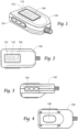
- a user interface 110 is shown within a device such as pressure measuring sensor 120 which preferably has a digital display 132.
- the device 130 may be a device constructed to be primarily used to house the interface 110 and communicate with the at least one sensor 120 (shown in Fig. 5 ), having at least one of a physical button 134 and a virtual button 136 (virtual buttons used, for instance, in a touchscreen environment) provided on the display 132.
- the at least one physical button 134 and/or virtual button 136 may be configured to turn the interface 110 on and off (i.e., a power button), to actively synchronize the at least one remote sensor 120 and the smartphone 242 (i.e., a "sync” button), to clear the current readings (i.e., a "zero” button), and/or to select the units in which the readings will be supplied (i.e., a "units” button).
- Smartphone 242 can also duplicate the readout of interface 110, if desired.
- the device 130 carries a magnet 138.
- the magnet 138 is configured to retain the device 130 in the engine compartment ( Fig. 6 ) while readings are taken (e.g., pressures are being measured), because it is contemplated that some measuring will be performed while the vehicle (the interior of which is shown in Fig. 6 ) is being driven.
- the interface 110 be downloadable as an "Application” or "App” on a Smartphone 242 ( Figure 6 ). Referring now to the app itself, with the power on, there is a sync button on the red unit, which then engages the phone. The phone confirms the connection.
- Logs are taken, in which recorded information as readings are taken, is saved and charted. Several logs can be recorded. From a list of sequential logs, each log can be opened and analyzed by a technician, and notes can be added to each log. From the log list, the logs can be exported from the app, for instance by an email in formats such as jpg, png, csv, and provided with a summary.
- buttons 134 can be for: 1) Units - to switch measurement units; 2) Mode - to switch from positive to negative (vacuum) pressure readings; 3) Cylinder - to allow a user to select how many cylinders the engine has; for instance, in a four cylinder engine, all four cylinders could be contained in one log file.
- buttons 134 could also be a 4) Menu, to disconnect Bluetooth, or reconnect; 5) Settings, in which the unit can be set to continuous record, logging interval (how many minutes and seconds each sample should be), sound alerts, vibration alerts, and refresh rate between sampling intervals.
- a Record button can be set to begin a test.
- a Zero button can zero out the pressure reading.
- a Graph button can bring up a test result graphical reading in real time. This data can ultimately be saved as the log.
- the interface 110 and the at least one remote sensor 120 are preferably configured to wirelessly interact via BLUETOOTH ® , Wi-Fi, ZIGBEE ® , with smartphone 242 and/or any other wireless technology now known.
- the system 100 comprises a user interface 110 and at least one remote pressure measuring sensor 120 carried by the device 130.
- the sensor 120 is contained within unit 100.
- This sensor is preferably fuel pressure, compression and/or vacuum, but other sensors can be carried by the unit 100 such as temperature, humidity or electrical readouts. Measurement outputs can be in psi, in/Hg, kpA, mm/hg, or bars, for instance.
- Unit 100 carries couplings and hose 240, for attachment to an area of inquiry in the vehicle. For instance, a fuel line, spark plug hole, or anywhere else in the vehicle of interest can receive the couplings and hose 240.
- a plurality of couplings 240 can be provided; for instance, a standard fuel setup with pressure bleed off, which can work with different fuel adaptors: Fuel injection; inline or direct port adaptors; or a Universal interchange connector.
- compression adaptors can be used, such as hose style, DOHC cam, or units available from Lang Tools with SKU numbers 73106, 73109, 73110 for example.
- the unit 100 can be carried (magnetically by magnet 138 as shown in Fig. 4 ) inside the vehicle as shown in Fig. 6 , the unit can transmit data to unit 242, 110 (e.g., a smart phone) while the vehicle is running and/or underway. In this manner, a dual readout 132 of the unit 100 is simultaneously displayed at unit 242, and can be logged or monitored.
- unit 242, 110 e.g., a smart phone
- a dual readout 132 of the unit 100 is simultaneously displayed at unit 242, and can be logged or monitored.
- One advantage of the present invention is the ability to remotely read measurements from an interior of the vehicle engine compartment, and record measurements on an additional device, all while the vehicle is underway.
- the pressure measurements taken by the at least one remote sensor 120 are as an example, taken in one second intervals; however, smaller or larger intervals are also possible.
- the pressure measurements taken by the at least one sensor 120 are provided on the display 132 of the device 130.
- Synchronization of the remote sensor 120 to the interface 110 preferably occurs at the same rate the remote sensor 120 measures the pressures and substantially simultaneously.
- Figures 5 and 6 show a remote sensor 120 used for measuring cylinder pressure, for example.
- a coupling system 240 such as a hose, couples the unit 130 with the portion of the vehicle to be analyzed, such as in Fig. 6 .
- the sensor 120 is coupled, by way of coupling system 240, for example a spark plug hole 14 in a cylinder head 12 of an engine 10.
- the following example of the system 100 in use is described as it pertains to a method for measuring cylinder pressure.
- a fuel delivery system may be disengaged and the coil (not shown) is disconnected. Remove all spark plugs (not shown) from their respective spark plug hole 14 in the cylinder head 12 and couple the remote sensor 120 (via coupling system 240) with the spark plug hole 14.
- Sensors 120 are then synchronized with the smart phone 242.
- the engine 10 is turned over and the pressure transducer 120 measures the pressure formed within the engine cylinder (not shown) for at least a complete intake-compression-ignition-exhaust cycle, possibly more than one complete cycle.
- the pressure measurements are transmitted to the interface 242 wirelessly. It is contemplated that the cylinder pressure for the at least one intake-compression-ignition-exhaust cycle may be measured, transmitted, viewed on the display 132, and recorded for each cylinder.
- the measured pressure values for each cylinder are preferably saved for reference by an application on the smart phone 242.
- Sensor 120 carried by unit 130 according to the present invention can be used for measuring fuel pressure for instance.
- the remote sensor 120 may be equipped to interface with a fuel system via a Schrader valve test port (not shown).
- An additional remote sensor 120 can be used for measuring transmission oil pressure, for measuring engine oil pressure, compression, vacuum and the like.
Landscapes
- Physics & Mathematics (AREA)
- General Physics & Mathematics (AREA)
- Chemical & Material Sciences (AREA)
- Engineering & Computer Science (AREA)
- Combustion & Propulsion (AREA)
- Measuring Fluid Pressure (AREA)
Claims (4)
- Drahtloses Prüfsystem (100) zur Messung von Zielbetriebsparametern eines Kraftfahrzeugs während des Fahrens, das drahtlose Prüfsystem umfassend:
eine Vorrichtung (100, 130), umfassend:ein Gehäuse;eine Kupplung (138) zwischen dem Gehäuse und dem Kraftfahrzeug in Form eines Magneten zum Festhalten der Vorrichtung im Maschinenraum;einen Sensor (120), der von dem Gehäuse getragen wird;eine kommunikative Kopplung (240), die von dem Gehäuse getragen wird, um das Gehäuse mit einem Abschnitt des zu analysierenden Fahrzeugs zu koppeln, damit der Sensor einen Zielbetriebsparameter des Kraftfahrzeugs messen kann, während das Kraftfahrzeug gefahren wird; eine lokale Benutzerschnittstelle (110), die von dem Gehäuse getragen wird und mit dem Sensor gekoppelt ist und eine Auslesung (132) umfasst;eine Steuerplatte, die von dem Gehäuse getragen wird, wobei die Steuerplatte betriebsmäßig mit dem Sensor gekoppelt ist; undeine entfernte Benutzerschnittstelle (242), die drahtlos mit dem Sensor verbunden ist;wobei der Sensor konfiguriert ist, um ein Signal von dem Kraftfahrzeug zu erfassen, das mindestens eines von Zylinderdruck, Kraftstoffdruck, Getriebeöldruck und Motoröldruck umfasst; unddie entfernte Benutzerschnittstelle (242) konfiguriert ist, um das Signal zu empfangen,wobei eine doppelte Auslesung (132) der Vorrichtung (100) gleichzeitig an der entfernten Benutzerschnittstelle (242) angezeigt wird und protokolliert oder überwacht werden kann. - Drahtloses Prüfsystem nach Anspruch 1, wobei die entfernte Benutzerschnittstelle (242) ein Mobiltelefon umfasst.
- Drahtloses Prüfsystem nach Anspruch 1, wobei die lokale Benutzerschnittstelle (110) eine Vielzahl von Steuerungen (136) umfasst, die Schalter zum Variieren von mindestens einer der Einstellungen, Einheiten, Modi und Zylinder umfassen.
- Verfahren zum Messen von Zielbetriebsparametern eines Kraftfahrzeugs, während sich das Kraftfahrzeug in Bewegung befindet, wobei das Verfahren unter Verwendung eines drahtlosen Prüfsystems nach einem der Ansprüche 1 bis 3 durchgeführt wird.
Applications Claiming Priority (1)
| Application Number | Priority Date | Filing Date | Title |
|---|---|---|---|
| US201662431237P | 2016-12-07 | 2016-12-07 |
Publications (3)
| Publication Number | Publication Date |
|---|---|
| EP3333809A1 EP3333809A1 (de) | 2018-06-13 |
| EP3333809B1 true EP3333809B1 (de) | 2025-05-14 |
| EP3333809C0 EP3333809C0 (de) | 2025-05-14 |
Family
ID=60629543
Family Applications (1)
| Application Number | Title | Priority Date | Filing Date |
|---|---|---|---|
| EP17206047.7A Active EP3333809B1 (de) | 2016-12-07 | 2017-12-07 | System zur drahtlosen druckprüfung und verfahren zur verwendung |
Country Status (3)
| Country | Link |
|---|---|
| US (1) | US10620076B2 (de) |
| EP (1) | EP3333809B1 (de) |
| MX (1) | MX379666B (de) |
Families Citing this family (5)
| Publication number | Priority date | Publication date | Assignee | Title |
|---|---|---|---|---|
| GB2563914B (en) * | 2017-06-29 | 2021-12-08 | Perkins Engines Co Ltd | Engine monitoring |
| BE1027195B1 (fr) * | 2019-04-17 | 2020-11-19 | Hubitools SA | Appareil de mesure de pression |
| AU2020405102A1 (en) * | 2019-12-20 | 2021-11-04 | Schneider Electric Systems Usa, Inc. | Smart wireless adapter |
| US12033442B2 (en) | 2021-03-18 | 2024-07-09 | A & E Incorporated | Testing system for measuring target operational parameters of a motor vehicle |
| USD1027685S1 (en) * | 2022-08-11 | 2024-05-21 | Shenzhen Foxwell Technology Co., Ltd | Auto tire sensor activation reset tool |
Citations (2)
| Publication number | Priority date | Publication date | Assignee | Title |
|---|---|---|---|---|
| US20010002552A1 (en) * | 1996-05-17 | 2001-06-07 | Peter Vinci | Digital remote gauge assembly |
| CN101894458A (zh) * | 2010-07-21 | 2010-11-24 | 北京爱德盛业科技有限公司 | 汽车燃油压力无线检测装置 |
Family Cites Families (19)
| Publication number | Priority date | Publication date | Assignee | Title |
|---|---|---|---|---|
| DE4419189A1 (de) | 1994-06-01 | 1995-12-07 | Bosch Gmbh Robert | Vorrichtung zur Diagnose von Kraftfahrzeugen |
| US5884202A (en) | 1995-07-20 | 1999-03-16 | Hewlett-Packard Company | Modular wireless diagnostic test and information system |
| US6029508A (en) | 1996-03-25 | 2000-02-29 | Snap-On Technologies, Inc. | Remote portable display unit with wireless transceiver and engine analyzing system incorporating same |
| US5663493A (en) | 1996-05-17 | 1997-09-02 | Fluke Corporation | Apparatus and method for measuring relative compression |
| US5875413A (en) | 1996-05-17 | 1999-02-23 | Waekon Corporation | Digital remote gauge assembly |
| USD390140S (en) | 1997-01-21 | 1998-02-03 | Measurement Specialties, Inc. | Tire pressure gauge |
| US20020134150A1 (en) | 2001-03-22 | 2002-09-26 | Shih-Pin Shih | Automatic car tire pressure detecting apparatus |
| US6701232B2 (en) | 2001-04-25 | 2004-03-02 | Fuji Jukogyo Kabushiki Kaisha | Vehicle management system |
| US6968733B2 (en) | 2004-01-12 | 2005-11-29 | Innova Electronics Corporation | Digital compression gauge |
| AT8411U3 (de) | 2006-03-02 | 2007-03-15 | Avl List Gmbh | Prüfstands-sensorvorrichtung, sowie prüfstand, vorzugsweise für kraftmaschinen |
| US8710796B2 (en) * | 2009-07-28 | 2014-04-29 | Bosch Automotive Service Solutions Llc | Electric vehicle supply equipment having a socket and a method of charging an electric vehicle |
| USD648236S1 (en) | 2010-08-12 | 2011-11-08 | Measurement Ltd. | Combination tire pressure and tread depth gauge |
| US20120109544A1 (en) | 2010-10-29 | 2012-05-03 | Spx Corporation | Digital compression recorder with specification database system and method |
| US9324197B2 (en) | 2011-03-11 | 2016-04-26 | Intelligent Agricultural Soultions | Method and system for managing the hand-off between control terminals |
| USD683643S1 (en) | 2011-10-31 | 2013-06-04 | Measurement, Ltd. | Combination tire pressure and tread depth gauge |
| USD671023S1 (en) | 2011-10-31 | 2012-11-20 | Measurement Ltd. | Combination tire pressure and tread depth gauge |
| USD700089S1 (en) | 2012-12-18 | 2014-02-25 | Gregory S. Sundheim | Pressure gauge |
| US9188505B2 (en) | 2013-06-21 | 2015-11-17 | Ford Global Technologies, Llc | Method and system for cylinder compression diagnostics |
| EP3674628A1 (de) | 2014-01-20 | 2020-07-01 | Parker Hannifin Corporation | Schlauchfreies sensorsystem für eine kältemitteleinheit |
-
2017
- 2017-12-05 US US15/832,357 patent/US10620076B2/en active Active
- 2017-12-06 MX MX2017015832A patent/MX379666B/es unknown
- 2017-12-07 EP EP17206047.7A patent/EP3333809B1/de active Active
Patent Citations (2)
| Publication number | Priority date | Publication date | Assignee | Title |
|---|---|---|---|---|
| US20010002552A1 (en) * | 1996-05-17 | 2001-06-07 | Peter Vinci | Digital remote gauge assembly |
| CN101894458A (zh) * | 2010-07-21 | 2010-11-24 | 北京爱德盛业科技有限公司 | 汽车燃油压力无线检测装置 |
Also Published As
| Publication number | Publication date |
|---|---|
| US20180156685A1 (en) | 2018-06-07 |
| MX2017015832A (es) | 2018-11-09 |
| EP3333809A1 (de) | 2018-06-13 |
| MX379666B (es) | 2025-03-11 |
| US10620076B2 (en) | 2020-04-14 |
| EP3333809C0 (de) | 2025-05-14 |
Similar Documents
| Publication | Publication Date | Title |
|---|---|---|
| EP3333809B1 (de) | System zur drahtlosen druckprüfung und verfahren zur verwendung | |
| EP3605036B1 (de) | Schwingungsanalysator und system für maschinenkomponentendiagnose | |
| US9419392B2 (en) | Automatic identification of an adapter in an on-board diagnostic system | |
| CN109716073A (zh) | 监测系统和方法 | |
| WO2006050380A3 (en) | Programmable automotive computer system | |
| US20110087461A1 (en) | Wireless data logging device | |
| US5602337A (en) | Abnormal sound detecting apparatus | |
| CA2717426A1 (en) | Wireless circular chart recorder | |
| US12140453B2 (en) | Environmental condition sensor with component diagnostics and optically communicated status | |
| US9043161B2 (en) | Modular system and methodology for testing and measurement | |
| US12499721B2 (en) | Testing system for measuring target operational parameters of a motor vehicle | |
| KR100524138B1 (ko) | 무선통신기술을 응용한 지능형 센서와 이를 이용한 진동 측정방법 | |
| US20170192405A1 (en) | Condition monitoring device and monitoring system using the same | |
| CN202372206U (zh) | 一种无人机空速气压高度校验装置 | |
| CN210536951U (zh) | 智能读数仪 | |
| CN211178575U (zh) | 一种多空间内环境远程检测装置 | |
| KR101178967B1 (ko) | 다수 개 센서의 서로 다른 주파수 할당 방법을 이용한 내압용기와 고압챔버 간의 신호전달 장치 및 방법 | |
| CN204790560U (zh) | 一种基于obd-ii接口的汽车智能诊断定位设备 | |
| GB2614938A (en) | Actuator with Bluetooth beacon | |
| CN103866068A (zh) | 用于高炉溜槽布料器上的振动检测装置及高炉溜槽布料器 | |
| CN208751631U (zh) | 一种非接触式车辆状态感知设备 | |
| CN222439015U (zh) | 一种无线智能力与力矩测量装置 | |
| CN106871958B (zh) | 测量系统 | |
| CN104166381A (zh) | 一种基于tcp_ip嵌入式网络的环境要素监控系统 | |
| CN219369794U (zh) | 一种带真空吸附结构的加速度传感器 |
Legal Events
| Date | Code | Title | Description |
|---|---|---|---|
| PUAI | Public reference made under article 153(3) epc to a published international application that has entered the european phase |
Free format text: ORIGINAL CODE: 0009012 |
|
| STAA | Information on the status of an ep patent application or granted ep patent |
Free format text: STATUS: THE APPLICATION HAS BEEN PUBLISHED |
|
| AK | Designated contracting states |
Kind code of ref document: A1 Designated state(s): AL AT BE BG CH CY CZ DE DK EE ES FI FR GB GR HR HU IE IS IT LI LT LU LV MC MK MT NL NO PL PT RO RS SE SI SK SM TR |
|
| AX | Request for extension of the european patent |
Extension state: BA ME |
|
| STAA | Information on the status of an ep patent application or granted ep patent |
Free format text: STATUS: REQUEST FOR EXAMINATION WAS MADE |
|
| 17P | Request for examination filed |
Effective date: 20181204 |
|
| RAX | Requested extension states of the european patent have changed |
Extension state: ME Payment date: 20181204 Extension state: BA Payment date: 20181204 |
|
| RBV | Designated contracting states (corrected) |
Designated state(s): AL AT BE BG CH CY CZ DE DK EE ES FI FR GB GR HR HU IE IS IT LI LT LU LV MC MK MT NL NO PL PT RO RS SE SI SK SM TR |
|
| STAA | Information on the status of an ep patent application or granted ep patent |
Free format text: STATUS: EXAMINATION IS IN PROGRESS |
|
| 17Q | First examination report despatched |
Effective date: 20210618 |
|
| P01 | Opt-out of the competence of the unified patent court (upc) registered |
Effective date: 20230718 |
|
| GRAP | Despatch of communication of intention to grant a patent |
Free format text: ORIGINAL CODE: EPIDOSNIGR1 |
|
| STAA | Information on the status of an ep patent application or granted ep patent |
Free format text: STATUS: GRANT OF PATENT IS INTENDED |
|
| INTG | Intention to grant announced |
Effective date: 20241210 |
|
| GRAS | Grant fee paid |
Free format text: ORIGINAL CODE: EPIDOSNIGR3 |
|
| GRAA | (expected) grant |
Free format text: ORIGINAL CODE: 0009210 |
|
| STAA | Information on the status of an ep patent application or granted ep patent |
Free format text: STATUS: THE PATENT HAS BEEN GRANTED |
|
| AK | Designated contracting states |
Kind code of ref document: B1 Designated state(s): AL AT BE BG CH CY CZ DE DK EE ES FI FR GB GR HR HU IE IS IT LI LT LU LV MC MK MT NL NO PL PT RO RS SE SI SK SM TR |
|
| REG | Reference to a national code |
Ref country code: GB Ref legal event code: FG4D |
|
| REG | Reference to a national code |
Ref country code: CH Ref legal event code: EP |
|
| REG | Reference to a national code |
Ref country code: IE Ref legal event code: FG4D |
|
| REG | Reference to a national code |
Ref country code: DE Ref legal event code: R096 Ref document number: 602017089438 Country of ref document: DE |
|
| U01 | Request for unitary effect filed |
Effective date: 20250612 |
|
| P04 | Withdrawal of opt-out of the competence of the unified patent court (upc) registered |
Free format text: CASE NUMBER: APP_28970/2025 Effective date: 20250618 |
|
| U07 | Unitary effect registered |
Designated state(s): AT BE BG DE DK EE FI FR IT LT LU LV MT NL PT RO SE SI Effective date: 20250623 |
|
| PG25 | Lapsed in a contracting state [announced via postgrant information from national office to epo] |
Ref country code: ES Free format text: LAPSE BECAUSE OF FAILURE TO SUBMIT A TRANSLATION OF THE DESCRIPTION OR TO PAY THE FEE WITHIN THE PRESCRIBED TIME-LIMIT Effective date: 20250514 |
|
| PG25 | Lapsed in a contracting state [announced via postgrant information from national office to epo] |
Ref country code: NO Free format text: LAPSE BECAUSE OF FAILURE TO SUBMIT A TRANSLATION OF THE DESCRIPTION OR TO PAY THE FEE WITHIN THE PRESCRIBED TIME-LIMIT Effective date: 20250814 Ref country code: GR Free format text: LAPSE BECAUSE OF FAILURE TO SUBMIT A TRANSLATION OF THE DESCRIPTION OR TO PAY THE FEE WITHIN THE PRESCRIBED TIME-LIMIT Effective date: 20250815 |
|
| PG25 | Lapsed in a contracting state [announced via postgrant information from national office to epo] |
Ref country code: PL Free format text: LAPSE BECAUSE OF FAILURE TO SUBMIT A TRANSLATION OF THE DESCRIPTION OR TO PAY THE FEE WITHIN THE PRESCRIBED TIME-LIMIT Effective date: 20250514 |
|
| PG25 | Lapsed in a contracting state [announced via postgrant information from national office to epo] |
Ref country code: HR Free format text: LAPSE BECAUSE OF FAILURE TO SUBMIT A TRANSLATION OF THE DESCRIPTION OR TO PAY THE FEE WITHIN THE PRESCRIBED TIME-LIMIT Effective date: 20250514 |
|
| PG25 | Lapsed in a contracting state [announced via postgrant information from national office to epo] |
Ref country code: RS Free format text: LAPSE BECAUSE OF FAILURE TO SUBMIT A TRANSLATION OF THE DESCRIPTION OR TO PAY THE FEE WITHIN THE PRESCRIBED TIME-LIMIT Effective date: 20250814 |
|
| PG25 | Lapsed in a contracting state [announced via postgrant information from national office to epo] |
Ref country code: IS Free format text: LAPSE BECAUSE OF FAILURE TO SUBMIT A TRANSLATION OF THE DESCRIPTION OR TO PAY THE FEE WITHIN THE PRESCRIBED TIME-LIMIT Effective date: 20250914 |
|
| PG25 | Lapsed in a contracting state [announced via postgrant information from national office to epo] |
Ref country code: SM Free format text: LAPSE BECAUSE OF FAILURE TO SUBMIT A TRANSLATION OF THE DESCRIPTION OR TO PAY THE FEE WITHIN THE PRESCRIBED TIME-LIMIT Effective date: 20250514 |
|
| PG25 | Lapsed in a contracting state [announced via postgrant information from national office to epo] |
Ref country code: CZ Free format text: LAPSE BECAUSE OF FAILURE TO SUBMIT A TRANSLATION OF THE DESCRIPTION OR TO PAY THE FEE WITHIN THE PRESCRIBED TIME-LIMIT Effective date: 20250514 |
|
| PG25 | Lapsed in a contracting state [announced via postgrant information from national office to epo] |
Ref country code: SK Free format text: LAPSE BECAUSE OF FAILURE TO SUBMIT A TRANSLATION OF THE DESCRIPTION OR TO PAY THE FEE WITHIN THE PRESCRIBED TIME-LIMIT Effective date: 20250514 |
|
| U20 | Renewal fee for the european patent with unitary effect paid |
Year of fee payment: 9 Effective date: 20251230 |