EP3333777A1 - Method and apparatus for harvesting an energy from a power cord - Google Patents
Method and apparatus for harvesting an energy from a power cord Download PDFInfo
- Publication number
- EP3333777A1 EP3333777A1 EP16306627.7A EP16306627A EP3333777A1 EP 3333777 A1 EP3333777 A1 EP 3333777A1 EP 16306627 A EP16306627 A EP 16306627A EP 3333777 A1 EP3333777 A1 EP 3333777A1
- Authority
- EP
- European Patent Office
- Prior art keywords
- power cord
- electrodes
- spikes
- energy
- conductive part
- Prior art date
- Legal status (The legal status is an assumption and is not a legal conclusion. Google has not performed a legal analysis and makes no representation as to the accuracy of the status listed.)
- Withdrawn
Links
Images


Classifications
-
- H—ELECTRICITY
- H01—ELECTRIC ELEMENTS
- H01Q—ANTENNAS, i.e. RADIO AERIALS
- H01Q1/00—Details of, or arrangements associated with, antennas
- H01Q1/12—Supports; Mounting means
- H01Q1/22—Supports; Mounting means by structural association with other equipment or articles
- H01Q1/2208—Supports; Mounting means by structural association with other equipment or articles associated with components used in interrogation type services, i.e. in systems for information exchange between an interrogator/reader and a tag/transponder, e.g. in Radio Frequency Identification [RFID] systems
- H01Q1/2225—Supports; Mounting means by structural association with other equipment or articles associated with components used in interrogation type services, i.e. in systems for information exchange between an interrogator/reader and a tag/transponder, e.g. in Radio Frequency Identification [RFID] systems used in active tags, i.e. provided with its own power source or in passive tags, i.e. deriving power from RF signal
-
- G—PHYSICS
- G06—COMPUTING; CALCULATING OR COUNTING
- G06K—GRAPHICAL DATA READING; PRESENTATION OF DATA; RECORD CARRIERS; HANDLING RECORD CARRIERS
- G06K19/00—Record carriers for use with machines and with at least a part designed to carry digital markings
- G06K19/06—Record carriers for use with machines and with at least a part designed to carry digital markings characterised by the kind of the digital marking, e.g. shape, nature, code
- G06K19/067—Record carriers with conductive marks, printed circuits or semiconductor circuit elements, e.g. credit or identity cards also with resonating or responding marks without active components
- G06K19/07—Record carriers with conductive marks, printed circuits or semiconductor circuit elements, e.g. credit or identity cards also with resonating or responding marks without active components with integrated circuit chips
- G06K19/0701—Record carriers with conductive marks, printed circuits or semiconductor circuit elements, e.g. credit or identity cards also with resonating or responding marks without active components with integrated circuit chips at least one of the integrated circuit chips comprising an arrangement for power management
- G06K19/0707—Record carriers with conductive marks, printed circuits or semiconductor circuit elements, e.g. credit or identity cards also with resonating or responding marks without active components with integrated circuit chips at least one of the integrated circuit chips comprising an arrangement for power management the arrangement being capable of collecting energy from external energy sources, e.g. thermocouples, vibration, electromagnetic radiation
-
- G—PHYSICS
- G06—COMPUTING; CALCULATING OR COUNTING
- G06K—GRAPHICAL DATA READING; PRESENTATION OF DATA; RECORD CARRIERS; HANDLING RECORD CARRIERS
- G06K19/00—Record carriers for use with machines and with at least a part designed to carry digital markings
- G06K19/06—Record carriers for use with machines and with at least a part designed to carry digital markings characterised by the kind of the digital marking, e.g. shape, nature, code
- G06K19/067—Record carriers with conductive marks, printed circuits or semiconductor circuit elements, e.g. credit or identity cards also with resonating or responding marks without active components
- G06K19/07—Record carriers with conductive marks, printed circuits or semiconductor circuit elements, e.g. credit or identity cards also with resonating or responding marks without active components with integrated circuit chips
- G06K19/0701—Record carriers with conductive marks, printed circuits or semiconductor circuit elements, e.g. credit or identity cards also with resonating or responding marks without active components with integrated circuit chips at least one of the integrated circuit chips comprising an arrangement for power management
- G06K19/0702—Record carriers with conductive marks, printed circuits or semiconductor circuit elements, e.g. credit or identity cards also with resonating or responding marks without active components with integrated circuit chips at least one of the integrated circuit chips comprising an arrangement for power management the arrangement including a battery
-
- G—PHYSICS
- G06—COMPUTING; CALCULATING OR COUNTING
- G06K—GRAPHICAL DATA READING; PRESENTATION OF DATA; RECORD CARRIERS; HANDLING RECORD CARRIERS
- G06K19/00—Record carriers for use with machines and with at least a part designed to carry digital markings
- G06K19/06—Record carriers for use with machines and with at least a part designed to carry digital markings characterised by the kind of the digital marking, e.g. shape, nature, code
- G06K19/067—Record carriers with conductive marks, printed circuits or semiconductor circuit elements, e.g. credit or identity cards also with resonating or responding marks without active components
- G06K19/07—Record carriers with conductive marks, printed circuits or semiconductor circuit elements, e.g. credit or identity cards also with resonating or responding marks without active components with integrated circuit chips
- G06K19/0701—Record carriers with conductive marks, printed circuits or semiconductor circuit elements, e.g. credit or identity cards also with resonating or responding marks without active components with integrated circuit chips at least one of the integrated circuit chips comprising an arrangement for power management
- G06K19/0707—Record carriers with conductive marks, printed circuits or semiconductor circuit elements, e.g. credit or identity cards also with resonating or responding marks without active components with integrated circuit chips at least one of the integrated circuit chips comprising an arrangement for power management the arrangement being capable of collecting energy from external energy sources, e.g. thermocouples, vibration, electromagnetic radiation
- G06K19/0708—Record carriers with conductive marks, printed circuits or semiconductor circuit elements, e.g. credit or identity cards also with resonating or responding marks without active components with integrated circuit chips at least one of the integrated circuit chips comprising an arrangement for power management the arrangement being capable of collecting energy from external energy sources, e.g. thermocouples, vibration, electromagnetic radiation the source being electromagnetic or magnetic
- G06K19/0709—Record carriers with conductive marks, printed circuits or semiconductor circuit elements, e.g. credit or identity cards also with resonating or responding marks without active components with integrated circuit chips at least one of the integrated circuit chips comprising an arrangement for power management the arrangement being capable of collecting energy from external energy sources, e.g. thermocouples, vibration, electromagnetic radiation the source being electromagnetic or magnetic the source being an interrogation field
-
- G—PHYSICS
- G06—COMPUTING; CALCULATING OR COUNTING
- G06K—GRAPHICAL DATA READING; PRESENTATION OF DATA; RECORD CARRIERS; HANDLING RECORD CARRIERS
- G06K19/00—Record carriers for use with machines and with at least a part designed to carry digital markings
- G06K19/06—Record carriers for use with machines and with at least a part designed to carry digital markings characterised by the kind of the digital marking, e.g. shape, nature, code
- G06K19/067—Record carriers with conductive marks, printed circuits or semiconductor circuit elements, e.g. credit or identity cards also with resonating or responding marks without active components
- G06K19/07—Record carriers with conductive marks, printed circuits or semiconductor circuit elements, e.g. credit or identity cards also with resonating or responding marks without active components with integrated circuit chips
- G06K19/0701—Record carriers with conductive marks, printed circuits or semiconductor circuit elements, e.g. credit or identity cards also with resonating or responding marks without active components with integrated circuit chips at least one of the integrated circuit chips comprising an arrangement for power management
- G06K19/0715—Record carriers with conductive marks, printed circuits or semiconductor circuit elements, e.g. credit or identity cards also with resonating or responding marks without active components with integrated circuit chips at least one of the integrated circuit chips comprising an arrangement for power management the arrangement including means to regulate power transfer to the integrated circuit
-
- G—PHYSICS
- G06—COMPUTING; CALCULATING OR COUNTING
- G06K—GRAPHICAL DATA READING; PRESENTATION OF DATA; RECORD CARRIERS; HANDLING RECORD CARRIERS
- G06K19/00—Record carriers for use with machines and with at least a part designed to carry digital markings
- G06K19/06—Record carriers for use with machines and with at least a part designed to carry digital markings characterised by the kind of the digital marking, e.g. shape, nature, code
- G06K19/067—Record carriers with conductive marks, printed circuits or semiconductor circuit elements, e.g. credit or identity cards also with resonating or responding marks without active components
- G06K19/07—Record carriers with conductive marks, printed circuits or semiconductor circuit elements, e.g. credit or identity cards also with resonating or responding marks without active components with integrated circuit chips
- G06K19/0716—Record carriers with conductive marks, printed circuits or semiconductor circuit elements, e.g. credit or identity cards also with resonating or responding marks without active components with integrated circuit chips at least one of the integrated circuit chips comprising a sensor or an interface to a sensor
-
- G—PHYSICS
- G06—COMPUTING; CALCULATING OR COUNTING
- G06K—GRAPHICAL DATA READING; PRESENTATION OF DATA; RECORD CARRIERS; HANDLING RECORD CARRIERS
- G06K19/00—Record carriers for use with machines and with at least a part designed to carry digital markings
- G06K19/06—Record carriers for use with machines and with at least a part designed to carry digital markings characterised by the kind of the digital marking, e.g. shape, nature, code
- G06K19/067—Record carriers with conductive marks, printed circuits or semiconductor circuit elements, e.g. credit or identity cards also with resonating or responding marks without active components
- G06K19/07—Record carriers with conductive marks, printed circuits or semiconductor circuit elements, e.g. credit or identity cards also with resonating or responding marks without active components with integrated circuit chips
- G06K19/077—Constructional details, e.g. mounting of circuits in the carrier
- G06K19/07749—Constructional details, e.g. mounting of circuits in the carrier the record carrier being capable of non-contact communication, e.g. constructional details of the antenna of a non-contact smart card
- G06K19/07773—Antenna details
-
- H—ELECTRICITY
- H01—ELECTRIC ELEMENTS
- H01R—ELECTRICALLY-CONDUCTIVE CONNECTIONS; STRUCTURAL ASSOCIATIONS OF A PLURALITY OF MUTUALLY-INSULATED ELECTRICAL CONNECTING ELEMENTS; COUPLING DEVICES; CURRENT COLLECTORS
- H01R13/00—Details of coupling devices of the kinds covered by groups H01R12/70 or H01R24/00 - H01R33/00
- H01R13/62—Means for facilitating engagement or disengagement of coupling parts or for holding them in engagement
- H01R13/639—Additional means for holding or locking coupling parts together, after engagement, e.g. separate keylock, retainer strap
- H01R13/6392—Additional means for holding or locking coupling parts together, after engagement, e.g. separate keylock, retainer strap for extension cord
-
- H—ELECTRICITY
- H02—GENERATION; CONVERSION OR DISTRIBUTION OF ELECTRIC POWER
- H02J—CIRCUIT ARRANGEMENTS OR SYSTEMS FOR SUPPLYING OR DISTRIBUTING ELECTRIC POWER; SYSTEMS FOR STORING ELECTRIC ENERGY
- H02J50/00—Circuit arrangements or systems for wireless supply or distribution of electric power
- H02J50/05—Circuit arrangements or systems for wireless supply or distribution of electric power using capacitive coupling
Definitions
- the technical field of the disclosed method and apparatus is related to energy harvesting for powering devices such as sensors embedded in RFID tags.
- Smart home and smart building applications generally rely on deploying battery powered sensors in the home or building environment so as to measure and collect data in order to provide enhanced services.
- a huge variety of such sensors emerge as part of the Internet of Things trend, and include measurement of for example temperature, pressure, humidity, or magnetic field. Such sensors further include for example presence detection or door/window opening status detection.
- a first drawback of battery powered sensors is the cost of the battery which impacts the cost of the whole solution.
- a second drawback is the required maintenance of the system: batteries need to be monitored and regularly changed.
- a salient idea of the present principles is to harvest an energy from a power cord, by mounting two electrodes around the power cord, wherein the electrodes comprise a first conductive part being partially cylindrical around an axis, and a plurality of spikes, originating from the first conductive part, directed towards the axis, and inserted in an insulating envelope of the power cord, so as to increase the capacitive coupling to the wires inside the power cord and to increase the amount of harvested energy by the two electrodes.
- a device such as for example a wireless RFID tag is advantageously powered by the energy harvested by the two electrodes.
- the device comprises at least two electrodes mounted around the power cord, wherein at least one of the two electrodes comprises a plurality of spikes inserted in an insulating envelope of the power cord.
- the at least one of the two electrodes comprises a first conductive part being partially cylindrical around an axis, the spikes originating from the first conductive part and being directed towards the axis.
- At least one spike is a blade of material along the axis.
- the spikes of the plurality of spikes have a same form.
- the spikes of the plurality of spikes are regularly distributed around the first conductive part.
- the spikes are conductive, with a length being strictly smaller than a thickness of the insulating envelope.
- the spikes are of a dielectric material and inserted in the insulating envelope up to a conductive part of the power cord.
- the device is powered by the harvested energy.
- the device is powered by the harvested energy.
- the device is a wireless tag.
- the device is a RFID tag.
- the device further comprises a capacitor adapted to store the harvested energy.
- the device further comprises a sensor.
- the device further comprises an impulse detector.
- a method for powering a device comprises:
- the present embodiments may be employed in any combination or sub-combination.
- the present principles are not limited to the described variants, and any arrangement of variants and embodiments can be used.
- the present principles are not limited to the described forms of spikes examples.
- the present principles are not further limited to the described positioning of spikes on the first conductive part and are applicable to any other positioning of spikes.
- the present principles are not further limited to a RFI D tag and any other type of tag is applicable to the disclosed principles.
- any characteristic, variant or embodiment described for the device is compatible with a method for powering the device.
- a possible approach to deploy battery less sensor devices is to harvest an energy, for example from a power cord.
- power cords are highly available in homes and buildings, so that relying on a power cord availability to deploy a sensing device does not represent a strong deployment constraint.
- Some methods are known to harvest an energy from power cords. Most of energy harvesters from power cords use magnetic coupling. This technique requires current flowing in the power cord which represents some limitations. Indeed the amount of energy harvested strongly depends on the amount of power being consumed by devices connected to the power cord.
- Figure 1 represents an example of an electric field energy harvesting technique.
- the energy is harvested from two partially cylindrical electrodes 100 and 101 mounted around a power cord 10 over a length L and separated by a distance e.
- the energy harvested is stored in a storage module for example represented by an electrical diagram 11 comprising four diodes D 1 , D 2 , D 3 , D 4 and a storage capacitor C st .
- the amount of harvested energy for a given time duration is directly related to the length L of the electrodes 100, 101 and remains limited for lengths below ten to fifteen centimeters.
- Figure 2a shows an example of a cross-section view of a power cord 10 with the two partially cylindrical electrodes 100, 101, supposed of length L
- Figure 2b shows the corresponding modeling in an electrical circuit.
- the power cord 10 comprises a hot wire 21 and a neutral wire 22, embedded into a main insulating envelope 20.
- the hot wire 21 comprises a conducting part 210, itself embedded into an individual insulating envelope 211.
- the neutral wire 22 comprises a conducting part 220, itself embedded into an individual insulating envelope 221.
- the two electrodes 100, 101 are capacitively coupled to the hot 21 and neutral 22 wires and an energy is harvested from the leakage electric field which generates a current corresponding to the displacement current according to Maxwell's equation.
- This current is used to charge a storage capacitor C st through a rectifying circuit using the diodes D 1 , D 2 , D 3 , D 4 as shown in Figure 1 .
- the coupling capacitors to the hot wire 21 are denoted C H1 for the electrode 100 and C H2 for the electrode 101.
- the coupling capacitors to the neutral wire 22 are denoted C N1 for the electrode 100 and C N2 for the electrode 101.
- the coupling capacitor between the hot 21 and the neutral 22 wires is denoted C HN .
- C 12 denotes the direct coupling between both electrodes 100 and 101.
- the coupling capacitors have different values. Indeed, the values of these coupling capacitors depend on the exact geometry of the considered power cord 10 and the configuration of the electrodes 100, 101.
- Figure 2c shows an equivalent electrical circuit of an electrical field energy harvester, merging the modelling of figures 1 and 2b .
- the voltage at the edges of the storage capacitor C st denoted V out , is calculated as:
- FIG. 2d shows an application of the Thevenin Theorem, by replacing the passive circuit at the left side of terminals A-B, by the equivalent voltage source e AB and resistance R AB .
- the disclosed principles describe several specific and non-limiting embodiments where the geometry of the electrodes is advantageously adapted to increase the value of the coupling capacitors, so as to increase the amount of harvested energy.
- Figure 3a and Figure 3b illustrate a cross section of a device adapted to harvest an energy from a power cord 10 according to two specific and non-limiting embodiments of the disclosed principles.
- the device comprises at least two distinct electrodes 30A, 31 A, 30B, 31 B mounted around the power cord 10, and being electrically disconnected between each other.
- the figures 3a and 3b show a pair 30A-31 A of two electrodes (for figure 3a ) and a pair 30B-31 B of two electrodes (for figure 3b ), respectively mounted around the power cord 10.
- the principles will be described with one pair of two electrodes 30A-31 A, 30B-31 B, but any number of pair of electrodes mounted around the power cord is compatible with the disclosed principles.
- At least one electrode 30A, 30B of a pair 30A-31A, 30B-31 B of electrodes comprises a plurality of spikes 301, 302, 311, 312 inserted in an insulating envelope 20, 211 of the power cord 10.
- both electrodes 30A, 31A of a pair 30A-31A are identical and comprise a same plurality of spikes, of a similar geometry.
- a similar geometry of both electrodes 30A, 31 A advantageously improves the capacitive coupling to the conductive parts 210, 220 of the wires 21 and 22..
- the power cord 10 illustrated in figures 1 , 2a and 3a-3b comprises two types of insulated envelopes: an individual insulating envelope 211, 221 around each of the conductive part 210, 211 of each wire 21, 22, and a main insulating envelope 20 around both isolated wires 21, 22.
- insulating envelopes such as for example a single unique insulating envelope are compatible with the disclosed principles.
- At least one electrode 30A, 30B of a pair of electrodes, (or each electrode 30A, 31 A, 30B-31 B, of a pair of electrodes depending on the variant) comprises a first conductive part 300 being partially cylindrical around an axis.
- the first conductive part 300 is metallic.
- the term conductive implies a high level of electrical conductivity.
- the form of the first conductive part 300 is typically closed to a semi-cylinder, but with an angle strictly less than 180°as illustrated in the figures 3a, 3b , 4a, 4b . Indeed two electrodes with a first conductive part 300 of an angle of 180°would be in short circuit w hen mounted on the power cord. Any partially cylindrical form with an angle less than 180° is compatible with the disclosed principles.
- the axis of the partially cylindrical conductive part 300 of the electrode 30A, 31 A, 30B, 31 B is longitudinal to the electrode 30A, 31 A, 30B, 31 B and perpendicular to the cross section plan of figures 3a, and 3b .
- the electrodes 30A, 31 A, 30B, 31 B are longitudinally mounted on the power cord 10.
- the axis of the electrode partial cylinder is also the axis of the power cord 10.
- the plurality of spikes 301, 302, 311, 312 of the electrode 30A, 31 A, 30B, 31 B originate from the partially cylindrical conductive part 300 of the electrode 30A, 31 A, 30B, 31 B and are directed towards the axis of the partially cylindrical conductive part 300.
- At least one spike 301, 302, 311, 312 is a contiguous blade of a same material along the axis of the partially cylindrical conductive part 300.
- the spikes are conical, and directed towards the axis in the cross section view.
- the spikes are a discontinuous blade of a same material along the axis of the partially cylindrical conductive part 300.
- all the spikes 301, 302, 311, 312 of the electrodes 30A, 31 A, 30B, 31 B are represented with a same form and regularly distributed around the electrodes 30A, 31 A, 30B, 31 B. But any arrangement and geometry of the spikes on the first conductive part 300, adapted to increase the capacitive coupling of the electrodes 30A, 31 A, 30B, 31 B is compatible with the disclosed principles.
- each spike 301, 302, 311,312 occupies a surface of the first conductive part 300 corresponding to a first angle ⁇ 1 of the first partially cylindrical conductive part 300.
- An interval between two consecutive spikes 301, 302 further corresponds to a second angle ⁇ 2 of the first partially cylindrical conductive part 300.
- the spikes 301, 302 of the electrodes 30A, 31 A are conductive.
- the spikes 301, 302 are for example made of a same conductive material as the first partially cylindrical part 300 of the electrode 30A.
- the spikes 301, 302 are also metallic.
- the conductive spikes 301, 302 have a length strictly smaller than a thickness of the overall insulating envelope 20, 211, 221 of the power cord 10.
- the conductive spikes 301, 302 do not enter in contact with the conductive part 210, 220 or the wire 21, 22 so as to avoid an electrical short circuit of the electrode 30A, 31 A.
- Fincrease represents the increase factor of the capacitance induced by the electrode 30A, 31 A (i.e. C H1 or C N2 ) expressed as function of its geometrical parameters ⁇ and I.
- the harvested energy improvement approaches a factor of ten.
- the amount of harvested energy from conductive electrodes 30A, 31 A according to the described embodiment is multiplied by ten compared to the harvested power energy only partially cylindrical conductive electrodes 100, 101 without any spikes 301, 302.
- the spikes 311, 312 of the electrodes 30B, 31 B are made in a dielectric material.
- a dielectric material despite of a very low conductivity is not conductive in the sense of the disclosed principles.
- the dielectric spikes 311, 312 are fixed on the surface of the first conductive partially cylindrical part 300 of the electrode 30B.
- the dielectric spikes 311,312 have a length smaller than or equal to a thickness of the overall insulating envelope 20, 211, 221 of the power cord 10.
- the dielectric spikes 311, 312 are inserted in the insulating envelope 20, 211, 221 of the power cord 10 up to the conductive part 210, 220 of the power cord 10.
- the material of the spikes 311, 312 is dielectric, no electrical short circuit is created as the dielectric spikes 311, 312 enter in contact with the conductive part 210, 220 of the wire 21, 22.
- the harvested energy improvement approaches a factor of four.
- the amount of harvested energy from metallo-dielectric electrodes 30B, 31 B according to the described embodiment is multiplied by four compared to the harvested energy from only partially cylindrical conductive electrodes 100, 101 without any spike.
- Metallo-dielectic electrodes 30B, 31 B according to the disclosed principles are easier to install on power cords 10 than the electrodes 30A, 31A according to the conductive embodiment, as it does not matter whether the dielectric spikes 311, 312 enter in contact with a conductive part 210, 220 of the power cord. But the amount of energy harvested from the metallo-dielectric electrodes 30B, 31 B is smaller than an amount of energy harvested from electrodes 30A, 31 A according to the conductive embodiment in similar conditions.
- Figure 4a and Figure 4b illustrate two further specific and non-limitative embodiments of the disclosed principles.
- Figure 4a represents a cross section of a power cord 12 of a different form, the section of the power cord 12 being ovoid and not fully circular.
- Figure 4a represents two metallo-dielectric electrodes 30B, 31 B mounted around the power cord 12, wherein each of the metallo-dielectric electrodes 30B, 31 B comprises a partially cylindrical first conductive part 300, and a plurality of spikes 311, 312 made of a dielectric material and inserted in an insulating envelope of the power cord 12 up to a conductive part of the power cord.
- FIG. 4b represents yet another embodiment of two metallo-dielectric electrodes 30B, 31 B mounted around a power cord 10, wherein both electrodes are further connected together by a piece of dielectric material 315.
- Such a configuration wherein the two electrodes 30B-31 B constitute a single dielectric piece of material being partially metalized is advantageous as it easier to manufacture and to deploy on power cords.
- FIG. 5a depicts a wireless tag device 5A adapted to harvest an energy from a power cord according to a specific and non-limiting embodiment of the disclosed principles.
- the wireless tag device is for example a RFID tag device.
- the tag device is described as a RFID tag device but any other kind of wireless tag device such as for example a Bluetooth tag is compatible with the disclosed principles.
- the RFID (or Bluetooth) tag device 5A comprises a RFID (or Bluetooth) integrated circuit 54 connected to an antenna 58.
- the RFID integrated circuit 54 and the antenna 58 constitute a wireless network interface for sending / receiving a modulated RF carrier to / from a wireless interrogator.
- the wireless network interface belongs to a set comprising:
- the RFID integrated circuit 54 is configured to receive its operating energy from a modulated RF carrier captured by the antenna 58, and to send a backscattered reply.
- the RFID integrated circuit 54 is also adapted to receive a further energy for example harvested by at least two electrodes 501, 502 mounted around a power cord according to any variant and/or embodiment of the disclosed principles.
- a possible example of such RFID integrated circuit 54 that can be further powered by another source or energy than the RF carrier reception, are the SL3S4011 from NXP, or the Monza X Chip from Impjin. Any RFID integrated circuit 54 that can be powered by another source or energy than the RF carrier reception is compatible with the disclosed principles.
- an energy storing module 52 stores an energy being harvested by the two electrodes 501, 502 mounted around the power cord, and not used by the integrated circuit 54.
- the energy storage module for example comprises a storage capacitor and a full wave rectifier comprising four diodes adapted to convert an analog current AC input providing from the electrodes 501, 502 into a direct current DC output.
- a possible value of the storage capacitor is 22 ⁇ F, and the four diodes are for example small signal fast switching diodes 1 N4148 from Vishay Semiconductors.
- An example of energy storing module is also illustrated in figure 1 as an electrical circuit 11.
- Powering a passive RFID tag device 5A with an energy harvested from a power cord is advantageous as it allows to extend the coverage of the RFID system: the RFID tag uses the harvested energy from the power cord in addition to the energy received from the reception of the modulated RF carrier by the antenna, so as to send back the backscattered reply.
- the read sensitivity is improved by 5 dB (from -18 dBm to -23 dBm) while the write sensitivity is improved by up to 12 dB (from -11 dBm to -23 dBm). That translates in terms of range by doubling the read range and by multiplying the write range by a factor of 4.
- FIG. 5b depicts a wireless tag device 5B adapted to harvest an energy from a power cord according to another specific and non-limiting embodiment of the disclosed principles.
- the wireless tag device 5B for example a RFID tag device comprises the same elements as the wireless tag device 5A, i.e. a RFID integrated circuit 54, an antenna 58, at least two electrodes 501, 502 and an optional energy storage module 52.
- the RFID tag device 5B further comprises a sensing 55 and computing 56 hardware being powered with the harvested energy. Powering such an active RFID tag device 5B with an energy harvested from a power cord is advantageous as it enables the deployment of battery less sensing RFID tag devices in smart home or building environments.
- the RFID tag device 5B for example comprises an ultra-low power microcontroller 56.
- the RFID tag device further comprises a sensor 55 configured to measure a variety of data, such as for example and without limitation an ambient temperature, an atmospheric pressure, a local magnetic field, ....
- the sensor 55, the microcontroller 56 and the RFID integrated circuit 54 are interconnected by a bus 500, such as for example an I2C interface.
- the I2C interface is a two-wire interface supported by many embedded systems, such as computers or electronic devices.
- the I2C functionality enables writing/reading information in a memory of the RFID tag device 5B, such as a data measured by the sensor 55, and then made available to a RFID interrogator via the RFID integrated circuit 54.
- the memory is a standalone memory (not represented) or included in the sensor 55, or in the microcontroller 56 or in the RFID integrated circuit 54.
- FIG. 5c depicts a wireless tag device 5C adapted to harvest an energy according to yet another specific and non-limiting embodiment of the disclosed principles.
- the wireless tag device 5C is mounted around a power cord, powering a specific device (not represented) such as a personal computer, a TV set, or any kind a device that can be switched on and off.
- the wireless tag device 5C is further adapted to detect that the specific device being powered by the power cord is being switched on or switched off. Detecting that an external device is being switched on or off may be interesting for various data mining or Internet of Things applications.
- a RFID tag device comprises the same elements as the wireless tag device 5B, i.e.
- a RFID integrated circuit 54 an antenna 58, at least two electrodes 501, 502, an optional energy storage module 52 and a micro-controller 56.
- the sensor 55 or device 5B is replaced in this embodiment by an impulse detector 57.
- the impulse detector 57 is merged with the RFID integrated circuit 54 in a single integrated circuit.
- the microcontroller 56 is coupled in signal communication 500 to the impulse detector 57.
- the impulse detector 57 is operative to detect when the specific device being powered by the power cord, is being switched on or off. More precisely, the impulse detector 57 is operative to receive an impulse response from the electrodes 501, 502 mounted around the power cord.
- the impulse detector 57 is operative to provide one of a single alert signal and a plurality of alert signals for the microcontroller 56 in response to the impulse response.
- the impulse response includes one of a single impulse waveform and a plurality of impulse waveforms in a time period.
- the impulse detector 57 generates the single alert signal when the impulse response includes the single impulse waveform.
- the impulse detector 57 generates the plurality of alert signals when the impulse response includes respective ones of the plurality of impulse waveforms.
- the microcontroller 56 is operative to determine a nature of the impulse response. The nature is determined as a switch-ON response when the single alert signal is received. The nature is determined as a switch-OFF response when the plurality of alert signals are received.
- the microcontroller 56 and the impulse detector 57 are advantageously powered from energy harvested from the power cord according to any variant or embodiment of the disclosed principles.
- the wireless tag device 5A, 5B, 5C is a battery less device and is further powered only with the harvested energy, meaning that the wireless tag device 5A, 5B, 5C is powered from the harvested energy in addition to the energy received by the antenna from the RF carrier.
- the wireless tag device 5A, 5B, 5C comprises a battery and is further powered also with the harvested energy. Powering the device comprising a battery with an energy harvested from a power cord is advantageous as it allows to preserve the battery and to extend its duration.
- Figure 6 describes a method for powering a device from an energy harvested from a power cord according to a specific and non-limiting embodiment of the disclosed principles.
- step S60 at least two distinct electrodes are mounted around a power cord, wherein the two distinct electrodes are electrically disconnected and at least one of the two electrodes comprises a plurality of spikes inserted in an insulated envelope of the power cord, according to any variant and/or embodiment described above.
- a device such as for example a wireless RFID tag is powered with an energy harvested from the power cord by the at least two electrodes and according to any variant and/or embodiment described above.
Landscapes
- Engineering & Computer Science (AREA)
- Computer Hardware Design (AREA)
- Microelectronics & Electronic Packaging (AREA)
- Physics & Mathematics (AREA)
- General Physics & Mathematics (AREA)
- Theoretical Computer Science (AREA)
- Electromagnetism (AREA)
- Computer Networks & Wireless Communication (AREA)
- Power Engineering (AREA)
- Charge And Discharge Circuits For Batteries Or The Like (AREA)
Abstract
A method for harvesting an energy from a power cord (10, 12) is disclosed. The method comprises mounting two electrodes (30A, 31A, 30B, 31B) around the power cord, wherein the electrodes comprise a first conductive part (300) being partially cylindrical around an axis, and a plurality of spikes (301, 302, 311, 312), originating from the first conductive part (300), directed towards the axis, and inserted in an insulating envelope (20, 211, 221) of the power cord, so as to increase the capacitive coupling to the wires (210, 220) inside the power cord and to increase the amount of harvested energy by the two electrodes. A device such as for example a wireless RFID tag (5A, 5B, 5C) is advantageously powered by the energy harvested by the two electrodes.
Description
- The technical field of the disclosed method and apparatus is related to energy harvesting for powering devices such as sensors embedded in RFID tags.
- Smart home and smart building applications generally rely on deploying battery powered sensors in the home or building environment so as to measure and collect data in order to provide enhanced services. A huge variety of such sensors emerge as part of the Internet of Things trend, and include measurement of for example temperature, pressure, humidity, or magnetic field. Such sensors further include for example presence detection or door/window opening status detection. There are known methods where such a battery powered sensor is coupled to a RFID tag that is able to report a value measured by the sensor towards a RFID interrogator. A first drawback of battery powered sensors is the cost of the battery which impacts the cost of the whole solution. A second drawback is the required maintenance of the system: batteries need to be monitored and regularly changed. These drawbacks represent significant barriers in the deployment of low cost and ease of use sensors dedicated to smart home applications. New methods and sensor devices are desired for measuring and reporting values without requiring the sensor device to be battery powered.
- A salient idea of the present principles is to harvest an energy from a power cord, by mounting two electrodes around the power cord, wherein the electrodes comprise a first conductive part being partially cylindrical around an axis, and a plurality of spikes, originating from the first conductive part, directed towards the axis, and inserted in an insulating envelope of the power cord, so as to increase the capacitive coupling to the wires inside the power cord and to increase the amount of harvested energy by the two electrodes. A device such as for example a wireless RFID tag is advantageously powered by the energy harvested by the two electrodes.
- To that end a device adapted to harvest an energy from a power cord is disclosed. The device comprises at least two electrodes mounted around the power cord, wherein at least one of the two electrodes comprises a plurality of spikes inserted in an insulating envelope of the power cord.
- According to a particularly advantageous variant, the at least one of the two electrodes comprises a first conductive part being partially cylindrical around an axis, the spikes originating from the first conductive part and being directed towards the axis.
- According to another particularly advantageous variant, at least one spike is a blade of material along the axis.
- According to another particularly advantageous variant, the spikes of the plurality of spikes have a same form.
- According to another particularly advantageous variant, the spikes of the plurality of spikes are regularly distributed around the first conductive part.
- According to another particularly advantageous variant,
- each spike occupies a surface of the first conductive part, the surface corresponding to a first angle of the partially cylindrical first conductive part;
- an interval between two consecutive spikes corresponds to a second angle of the partially cylindrical first conductive part, and
- a ratio of the first angle over a sum of the first angle and the second angle is between 1/2 and 2/3.
- According to another particularly advantageous variant, the spikes are conductive, with a length being strictly smaller than a thickness of the insulating envelope.
- According to another particularly advantageous variant, the spikes are of a dielectric material and inserted in the insulating envelope up to a conductive part of the power cord.
- According to another particularly advantageous variant, the device is powered by the harvested energy.
- According to another particularly advantageous variant, the device is powered by the harvested energy.
- According to another particularly advantageous variant, the device is a wireless tag.
- According to another particularly advantageous variant, the device is a RFID tag.
- According to another particularly advantageous variant, the device further comprises a capacitor adapted to store the harvested energy.
- According to another particularly advantageous variant, the device further comprises a sensor.
- According to another particularly advantageous variant, the device further comprises an impulse detector.
- In a second aspect a method for powering a device is also disclosed. The method comprises:
- mounting two electrodes around a power cord, wherein at least one of the two electrodes comprises a plurality of spikes inserted in an insulating envelope of the power cord;
- powering the device with an energy harvested from the power cord by the two electrodes.
- While not explicitly described, the present embodiments may be employed in any combination or sub-combination. For example, the present principles are not limited to the described variants, and any arrangement of variants and embodiments can be used. Moreover the present principles are not limited to the described forms of spikes examples. The present principles are not further limited to the described positioning of spikes on the first conductive part and are applicable to any other positioning of spikes. The present principles are not further limited to a RFI D tag and any other type of tag is applicable to the disclosed principles.
- Besides, any characteristic, variant or embodiment described for the device is compatible with a method for powering the device.
-
-
Figure 1 illustrates an example of harvesting an energy from a power cord according to a known method; -
Figures 2a depicts an example of a cross-section view of the power cord ofFigure 1 ; -
Figures 2b shows a modelling of the power cord ofFigure 2a in an electrical circuit according to a specific and non-limiting embodiment of the disclosed principles; -
Figure 2c shows an equivalent electrical circuit of an electrical field energy harvester according to a specific and non-limiting embodiment of the disclosed principles; -
Figure 2d illustrates an application of the Thevenin Theorem to the electrical circuit ofFigure 2c ; -
Figure 2e shows plots of amounts of harvested energy evolution over time according to a specific and non-limiting embodiment of the disclosed principles; -
Figure 3a and 3b respectively describe a cross-section view of two electrodes adapted to harvest an energy from a power cord according to two specific and non-limiting embodiments of the present principles; -
Figure 4a and 4b illustrate two further specific and non-limitative embodiments of the disclosed principles; -
Figure 5a, 5b and 5c depict three RFID tag devices adapted to harvest an energy from a power cord according to respectively three specific and non-limiting embodiments of the disclosed principles; -
Figure 6 describes a method for powering a device from energy harvested from a power cord according to a specific and non-limiting embodiment of the disclosed principles. - A possible approach to deploy battery less sensor devices is to harvest an energy, for example from a power cord. Indeed power cords are highly available in homes and buildings, so that relying on a power cord availability to deploy a sensing device does not represent a strong deployment constraint. Some methods are known to harvest an energy from power cords. Most of energy harvesters from power cords use magnetic coupling. This technique requires current flowing in the power cord which represents some limitations. Indeed the amount of energy harvested strongly depends on the amount of power being consumed by devices connected to the power cord. Some methods recently emerged for harvesting energy from power cords by using the electrical field. Such electric field energy harvesting techniques do not require current to flow in the power cord. The harvested energy is always available but remains relatively limited.
-
Figure 1 represents an example of an electric field energy harvesting technique. The energy is harvested from two partiallycylindrical electrodes power cord 10 over a length L and separated by a distance e. The energy harvested is stored in a storage module for example represented by an electrical diagram 11 comprising four diodes D1, D2, D3, D4 and a storage capacitor Cst. The amount of harvested energy for a given time duration, is directly related to the length L of theelectrodes -
Figure 2a shows an example of a cross-section view of apower cord 10 with the two partiallycylindrical electrodes Figure 2b shows the corresponding modeling in an electrical circuit. According to a specific and non-limiting embodiment, thepower cord 10 comprises ahot wire 21 and aneutral wire 22, embedded into a main insulatingenvelope 20. Thehot wire 21 comprises a conductingpart 210, itself embedded into an individualinsulating envelope 211. Similarly theneutral wire 22 comprises a conductingpart 220, itself embedded into an individualinsulating envelope 221. The twoelectrodes Figure 1 . InFigure 2b , the coupling capacitors to thehot wire 21 are denoted CH1 for theelectrode 100 and CH2 for theelectrode 101. By the same way, the coupling capacitors to theneutral wire 22 are denoted CN1 for theelectrode 100 and CN2 for theelectrode 101. The coupling capacitor between the hot 21 and the neutral 22 wires is denoted CHN. Finally C12, denotes the direct coupling between bothelectrodes electrodes electrodes power cord 10 and the configuration of theelectrodes -
Figure 2c shows an equivalent electrical circuit of an electrical field energy harvester, merging the modelling offigures 1 and2b . Infigure 2c , by applying the Thevenin theorem illustrated inFigure 2d , the voltage at the edges of the storage capacitor Cst, denoted Vout, is calculated as: -

where:-


- Rst represents the leakage resistance of the storage capacitor;
- eAB = A * Vrms ;
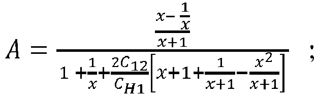

-

-
-
Figure 2d shows an application of the Thevenin Theorem, by replacing the passive circuit at the left side of terminals A-B, by the equivalent voltage source eAB and resistance RAB. In this calculation, the resistances of the diodes of the rectifier (in serial with RAB) are neglected, following a hypothesis of perfect diode. Therefore, for a given storage capacitor Cst, the harvested energy Eh is given by:
-
Figure 2e shows examples of harvested energy evolution over time calculated using the above formulas for values of coupling capacitors CH1=CN2, varying from 1pF to 100 pF. For these calculations the storage capacitor Cst value is chosen equal to 22µF. It appears clearly fromFigure 2e , that the amount of harvested energy is directly related to the values of the coupling capacitors CH1 and CN2. The disclosed principles describe several specific and non-limiting embodiments where the geometry of the electrodes is advantageously adapted to increase the value of the coupling capacitors, so as to increase the amount of harvested energy. -
Figure 3a and Figure 3b illustrate a cross section of a device adapted to harvest an energy from apower cord 10 according to two specific and non-limiting embodiments of the disclosed principles. The device comprises at least twodistinct electrodes power cord 10, and being electrically disconnected between each other. Thefigures 3a and 3b show apair 30A-31 A of two electrodes (forfigure 3a ) and apair 30B-31 B of two electrodes (forfigure 3b ), respectively mounted around thepower cord 10. For the sake of clarity, the principles will be described with one pair of twoelectrodes 30A-31 A, 30B-31 B, but any number of pair of electrodes mounted around the power cord is compatible with the disclosed principles. In a first variant, at least oneelectrode pair 30A-31A, 30B-31 B of electrodes comprises a plurality ofspikes envelope power cord 10. In a second variant bothelectrodes pair 30A-31A, are identical and comprise a same plurality of spikes, of a similar geometry. A similar geometry of bothelectrodes conductive parts wires power cord 10 illustrated infigures 1 ,2a and3a-3b comprises two types of insulated envelopes: an individualinsulating envelope conductive part wire envelope 20 around bothisolated wires electrode electrode conductive part 300 being partially cylindrical around an axis. For example the firstconductive part 300 is metallic. The term conductive implies a high level of electrical conductivity. The form of the firstconductive part 300 is typically closed to a semi-cylinder, but with an angle strictly less than 180°as illustrated in thefigures 3a, 3b ,4a, 4b . Indeed two electrodes with a firstconductive part 300 of an angle of 180°would be in short circuit w hen mounted on the power cord. Any partially cylindrical form with an angle less than 180° is compatible with the disclosed principles. The axis of the partially cylindricalconductive part 300 of theelectrode electrode figures 3a, and 3b . Theelectrodes power cord 10. In other words the axis of the electrode partial cylinder is also the axis of thepower cord 10. According to this specific and non-limiting embodiment, the plurality ofspikes electrode conductive part 300 of theelectrode conductive part 300. - In an advantageous variant, at least one
spike conductive part 300. In another variant (not represented), the spikes are conical, and directed towards the axis in the cross section view. In that variant the spikes are a discontinuous blade of a same material along the axis of the partially cylindricalconductive part 300. For the sake of clarity all thespikes electrodes electrodes conductive part 300, adapted to increase the capacitive coupling of theelectrodes - In an advantageous variant, wherein the
spikes conductive part 300, eachspike conductive part 300 corresponding to a first angle θ 1 of the first partially cylindricalconductive part 300. An interval between twoconsecutive spikes conductive part 300. A filling factor α is defined as a ratio of the second angle θ2 over a sum of the first angle θ 1 and the second angle
- According to a specific and non-limiting embodiment of the disclosed principles illustrated in
Figure 3a , thespikes electrodes spikes cylindrical part 300 of theelectrode 30A. For example, thespikes conductive spikes envelope power cord 10. As the length of thespikes envelope power cord 10, theconductive spikes conductive part wire electrode - Considering a as the radius of the
conductive part conductive part 300 of theelectrode spikes envelope conductive part wire electrode 
- C1 is the capacitance induced between the internal
conductive part wire electrode 
- Fincrease represents the increase factor of the capacitance induced by the
electrode - For a penetration of the conductor of 1.2mm, corresponding to a practical realization using for example a lamp power cord, it can be calculated that the capacitances are multiplied by 1, 2.5, 3 and 4 for α equals respectively to 0 (no penetration of the conductor), 1/2, 2/3 and 1.
- Practically using two
electrodes conductive electrodes conductive electrodes spikes - According to another specific and non-limiting embodiment of the disclosed principles illustrated in
Figure 3b , thespikes electrodes cylindrical part 300 of theelectrode 30B. According to this specific embodiment, the dielectric spikes 311,312 have a length smaller than or equal to a thickness of the overall insulatingenvelope power cord 10. Advantageously thedielectric spikes envelope power cord 10 up to theconductive part power cord 10. As the material of thespikes dielectric spikes conductive part wire - Considering the same notations as for the conductive embodiment (a, b, /), and further considering εr1 as a permittivity of the insulating
envelope power cord 10 and εr2 a permittivity of the dielectric material of the spikes 311,312, it can be demonstrated that the equivalent capacitance Ceq induced between the internalconductive part wire electrode 
conductive part wire electrode 

- Practically, from the above formula it can be calculated that using two metallo-
dielectric electrodes spikes permittivity 8, and a filling factor in the range of 2/3, the harvested energy improvement approaches a factor of four. In other words, the amount of harvested energy from metallo-dielectric electrodes conductive electrodes dielectic electrodes power cords 10 than theelectrodes dielectric spikes conductive part dielectric electrodes electrodes -
Figure 4a and Figure 4b illustrate two further specific and non-limitative embodiments of the disclosed principles.Figure 4a represents a cross section of apower cord 12 of a different form, the section of thepower cord 12 being ovoid and not fully circular.Figure 4a represents two metallo-dielectric electrodes power cord 12, wherein each of the metallo-dielectric electrodes conductive part 300, and a plurality ofspikes power cord 12 up to a conductive part of the power cord. Similarly, the disclosed principles are also applicable to conductive electrodes according to the conductive embodiment, wherein the conductive electrodes are mounted around an ovoid power cord (not represented).Figure 4b represents yet another embodiment of two metallo-dielectric electrodes power cord 10, wherein both electrodes are further connected together by a piece ofdielectric material 315. Such a configuration wherein the twoelectrodes 30B-31 B constitute a single dielectric piece of material being partially metalized is advantageous as it easier to manufacture and to deploy on power cords. -
Figure 5a depicts awireless tag device 5A adapted to harvest an energy from a power cord according to a specific and non-limiting embodiment of the disclosed principles. The wireless tag device is for example a RFID tag device. For the sake of clarity the tag device is described as a RFID tag device but any other kind of wireless tag device such as for example a Bluetooth tag is compatible with the disclosed principles. The RFID (or Bluetooth)tag device 5A comprises a RFID (or Bluetooth) integratedcircuit 54 connected to anantenna 58. The RFIDintegrated circuit 54 and theantenna 58 constitute a wireless network interface for sending / receiving a modulated RF carrier to / from a wireless interrogator. The wireless network interface belongs to a set comprising: - A UHF RFID Air interface for the 860 MHz-960 MHz band, following the national regulations;
- A UHF RFID Air interface for the 433 MHz band following the national regulations;
- A RFID Air interface for the ISM 2.4 GHz band following the national regulations;
- A RFID Air interface for the 5.2 - 5.8 GHz band following the national regulations.
- The RFID
integrated circuit 54 is configured to receive its operating energy from a modulated RF carrier captured by theantenna 58, and to send a backscattered reply. The RFIDintegrated circuit 54 is also adapted to receive a further energy for example harvested by at least twoelectrodes circuit 54 that can be further powered by another source or energy than the RF carrier reception, are the SL3S4011 from NXP, or the Monza X Chip from Impjin. Any RFID integratedcircuit 54 that can be powered by another source or energy than the RF carrier reception is compatible with the disclosed principles. Optionally anenergy storing module 52 stores an energy being harvested by the twoelectrodes circuit 54. The energy storage module for example comprises a storage capacitor and a full wave rectifier comprising four diodes adapted to convert an analog current AC input providing from theelectrodes figure 1 as anelectrical circuit 11. - Powering a passive
RFID tag device 5A with an energy harvested from a power cord is advantageous as it allows to extend the coverage of the RFID system: the RFID tag uses the harvested energy from the power cord in addition to the energy received from the reception of the modulated RF carrier by the antenna, so as to send back the backscattered reply. Typically by powering a SL3S4011/4021 integrated circuit from NXP using the capacitor stored energy, the read sensitivity is improved by 5 dB (from -18 dBm to -23 dBm) while the write sensitivity is improved by up to 12 dB (from -11 dBm to -23 dBm). That translates in terms of range by doubling the read range and by multiplying the write range by a factor of 4. -
Figure 5b depicts awireless tag device 5B adapted to harvest an energy from a power cord according to another specific and non-limiting embodiment of the disclosed principles. Thewireless tag device 5B, for example a RFID tag device comprises the same elements as thewireless tag device 5A, i.e. a RFID integratedcircuit 54, anantenna 58, at least twoelectrodes energy storage module 52. In addition, and according to this specific and non-limiting embodiment, theRFID tag device 5B further comprises asensing 55 andcomputing 56 hardware being powered with the harvested energy. Powering such an activeRFID tag device 5B with an energy harvested from a power cord is advantageous as it enables the deployment of battery less sensing RFID tag devices in smart home or building environments. TheRFID tag device 5B for example comprises anultra-low power microcontroller 56. The RFID tag device further comprises asensor 55 configured to measure a variety of data, such as for example and without limitation an ambient temperature, an atmospheric pressure, a local magnetic field, .... Thesensor 55, themicrocontroller 56 and the RFID integratedcircuit 54 are interconnected by abus 500, such as for example an I2C interface. The I2C interface is a two-wire interface supported by many embedded systems, such as computers or electronic devices. The I2C functionality enables writing/reading information in a memory of theRFID tag device 5B, such as a data measured by thesensor 55, and then made available to a RFID interrogator via the RFID integratedcircuit 54. According to different variants, the memory is a standalone memory (not represented) or included in thesensor 55, or in themicrocontroller 56 or in the RFID integratedcircuit 54. -
Figure 5c depicts a wireless tag device 5C adapted to harvest an energy according to yet another specific and non-limiting embodiment of the disclosed principles. The wireless tag device 5C is mounted around a power cord, powering a specific device (not represented) such as a personal computer, a TV set, or any kind a device that can be switched on and off. In that example, the wireless tag device 5C is further adapted to detect that the specific device being powered by the power cord is being switched on or switched off. Detecting that an external device is being switched on or off may be interesting for various data mining or Internet of Things applications. To that end the wireless tag device 5C, for example a RFID tag device comprises the same elements as thewireless tag device 5B, i.e. a RFID integratedcircuit 54, anantenna 58, at least twoelectrodes energy storage module 52 and amicro-controller 56. Thesensor 55 ordevice 5B is replaced in this embodiment by animpulse detector 57. In a variant (not represented), theimpulse detector 57 is merged with the RFID integratedcircuit 54 in a single integrated circuit. Themicrocontroller 56 is coupled insignal communication 500 to theimpulse detector 57. Theimpulse detector 57, is operative to detect when the specific device being powered by the power cord, is being switched on or off. More precisely, theimpulse detector 57 is operative to receive an impulse response from theelectrodes impulse detector 57 is operative to provide one of a single alert signal and a plurality of alert signals for themicrocontroller 56 in response to the impulse response. The impulse response includes one of a single impulse waveform and a plurality of impulse waveforms in a time period. Theimpulse detector 57 generates the single alert signal when the impulse response includes the single impulse waveform. Theimpulse detector 57 generates the plurality of alert signals when the impulse response includes respective ones of the plurality of impulse waveforms. Themicrocontroller 56 is operative to determine a nature of the impulse response. The nature is determined as a switch-ON response when the single alert signal is received. The nature is determined as a switch-OFF response when the plurality of alert signals are received. Themicrocontroller 56 and theimpulse detector 57, are advantageously powered from energy harvested from the power cord according to any variant or embodiment of the disclosed principles. - In a first variant of any of the previously described embodiment, the
wireless tag device wireless tag device wireless tag device -
Figure 6 describes a method for powering a device from an energy harvested from a power cord according to a specific and non-limiting embodiment of the disclosed principles. - In the step S60, at least two distinct electrodes are mounted around a power cord, wherein the two distinct electrodes are electrically disconnected and at least one of the two electrodes comprises a plurality of spikes inserted in an insulated envelope of the power cord, according to any variant and/or embodiment described above.
- In the step S64, a device, such as for example a wireless RFID tag is powered with an energy harvested from the power cord by the at least two electrodes and according to any variant and/or embodiment described above.
Claims (15)
- A device (5A, 5B, 5C) adapted to harvest an energy from a power cord (10, 12), the device (5A, 5B, 5C) comprising at least two electrodes (30A, 31 A, 30B, 31 B) mounted around the power cord (10, 12), wherein at least one of the two electrodes (30A, 31 A, 30B, 31 B) comprises a plurality of spikes (301, 302, 311, 312) inserted in an insulating envelope (20, 211, 221) of the power cord (10, 12).
- The device (5A, 5B, 5C) according to claim 1, wherein the at least one of the two electrodes (30A, 31 A, 30B, 31 B) comprises a first conductive part (300) being partially cylindrical around an axis, the spikes (301, 302, 311,312) originating from the first conductive part (300) and being directed towards the axis.
- The device (5A, 5B, 5C) according to claim 2, wherein at least one spike (301, 302, 311, 312) is a blade of material along the axis.
- The device (5A, 5B, 5C) according to any of claims 2 to 3, wherein the spikes (301, 302, 311,312) of the plurality of spikes have a same form.
- The device (5A, 5B, 5C) according to any of claims 2 to 4, wherein the spikes (301, 302, 311,312) of the plurality of spikes are regularly distributed around the first conductive part (300).
- The device (5A, 5B, 5C) according to claim 5, wherein:- each spike (301, 302, 311, 312) occupies a surface of the first conductive part (300), the surface corresponding to a first angle (θ1) of the partially cylindrical first conductive part (300);- an interval between two consecutive spikes corresponds to a second angle (θ2) of the partially cylindrical first conductive part (300), and- a ratio of the first angle (θ1) over a sum of the first angle (θ1) and the second angle (θ2) is between 1/2 and 2/3.
- The device (5A, 5B, 5C) according to any of claims 1 to 6, wherein the spikes (301, 302) are conductive, with a length being strictly smaller than a thickness of the insulating envelope (20, 211, 221).
- The device (5A, 5B, 5C) according to any of claims 1 to 6, wherein the spikes (311, 312) are of a dielectric material and inserted in the insulating envelope (20, 211, 221) up to a conductive part of the power cord (10, 12).
- The device (5A, 5B, 5C) according to any of claims 1 to 8, wherein the device (5A, 5B, 5C) is powered by the harvested energy.
- The device (5A, 5B, 5C) according to any of claims 1 to 9, wherein the device (5A, 5B, 5C) is a wireless tag.
- The device (5A, 5B, 5C) according to claim 10 wherein the device (5A, 5B, 5C) is a RFID tag.
- The device (5A, 5B, 5C) according to any claims 1 to 11, further comprising a capacitor adapted to store the harvested energy.
- The device (5A, 5B, 5C) according to any claims 1 to 12, further comprising a sensor (55).
- The device (5A, 5B, 5C) according to any claims 1 to 12, further comprising an impulse detector (57).
- A method for powering a device (5A, 5B, 5C), the method comprising:- mounting two electrodes (30A, 31 A, 30B, 31 B) around a power cord (10,12), wherein at least one of the two electrodes (30A, 31A, 30B, 31 B) comprises a plurality of spikes (301, 302, 311, 312) inserted in an insulating envelope (20, 211, 221) of the power cord (10,12);- powering the device (5A, 5B, 5C) with an energy harvested from the power cord (10, 12) by the two electrodes (30A, 31 A, 30B, 31 B).
Priority Applications (2)
| Application Number | Priority Date | Filing Date | Title |
|---|---|---|---|
| EP16306627.7A EP3333777A1 (en) | 2016-12-06 | 2016-12-06 | Method and apparatus for harvesting an energy from a power cord |
| US15/833,189 US20180175480A1 (en) | 2016-12-06 | 2017-12-06 | Method and apparatus for harvesting an energy from a power cord |
Applications Claiming Priority (1)
| Application Number | Priority Date | Filing Date | Title |
|---|---|---|---|
| EP16306627.7A EP3333777A1 (en) | 2016-12-06 | 2016-12-06 | Method and apparatus for harvesting an energy from a power cord |
Publications (1)
| Publication Number | Publication Date |
|---|---|
| EP3333777A1 true EP3333777A1 (en) | 2018-06-13 |
Family
ID=57714488
Family Applications (1)
| Application Number | Title | Priority Date | Filing Date |
|---|---|---|---|
| EP16306627.7A Withdrawn EP3333777A1 (en) | 2016-12-06 | 2016-12-06 | Method and apparatus for harvesting an energy from a power cord |
Country Status (2)
| Country | Link |
|---|---|
| US (1) | US20180175480A1 (en) |
| EP (1) | EP3333777A1 (en) |
Citations (4)
| Publication number | Priority date | Publication date | Assignee | Title |
|---|---|---|---|---|
| FR2672444A1 (en) * | 1991-02-06 | 1992-08-07 | Seram | Multi-pole connector for cables having several electrical conductors and application relating thereto |
| GB2486008A (en) * | 2010-12-01 | 2012-06-06 | Perpetuum Ltd | Sensor system |
| WO2015039664A1 (en) * | 2013-09-19 | 2015-03-26 | Remoni Aps | Energy harvesting device |
| US20160351994A1 (en) * | 2015-05-29 | 2016-12-01 | Thomson Licensing | Electrical activity sensor device for detecting electrical activity and electrical activity monitoring apparatus |
-
2016
- 2016-12-06 EP EP16306627.7A patent/EP3333777A1/en not_active Withdrawn
-
2017
- 2017-12-06 US US15/833,189 patent/US20180175480A1/en not_active Abandoned
Patent Citations (4)
| Publication number | Priority date | Publication date | Assignee | Title |
|---|---|---|---|---|
| FR2672444A1 (en) * | 1991-02-06 | 1992-08-07 | Seram | Multi-pole connector for cables having several electrical conductors and application relating thereto |
| GB2486008A (en) * | 2010-12-01 | 2012-06-06 | Perpetuum Ltd | Sensor system |
| WO2015039664A1 (en) * | 2013-09-19 | 2015-03-26 | Remoni Aps | Energy harvesting device |
| US20160351994A1 (en) * | 2015-05-29 | 2016-12-01 | Thomson Licensing | Electrical activity sensor device for detecting electrical activity and electrical activity monitoring apparatus |
Also Published As
| Publication number | Publication date |
|---|---|
| US20180175480A1 (en) | 2018-06-21 |
Similar Documents
| Publication | Publication Date | Title |
|---|---|---|
| Sample et al. | Photovoltaic enhanced UHF RFID tag antennas for dual purpose energy harvesting | |
| US20150253365A1 (en) | Sensors for electrical connectors | |
| CN103810479B (en) | Fingerprint acquisition system and finger print information acquisition method | |
| CN101140635B (en) | Sensor device having non-contact charge function and containers having the same | |
| EP3333970A1 (en) | Method and apparatus for harvesting an energy from a power cord | |
| CN109690256A (en) | The sensing of object | |
| CN105303205B (en) | A kind of flexible passive label, passive flexible temperature measuring equipment and wireless power networking temp measuring system | |
| EP2796834A1 (en) | Radio frequency identification system | |
| KR20150104530A (en) | Electrical activity sensor device for detecting electrical activity and electrical activity monitoring apparatus | |
| CN105136328B (en) | A kind of flexibility temperature measuring equipment | |
| Gulati et al. | CapHarvester: A stick-on capacitive energy harvester using stray electric field from AC power lines | |
| Daskalakis et al. | Soil moisture wireless sensing with analog scatter radio, low power, ultra-low cost and extended communication ranges | |
| Nikitin et al. | RFID paperclip tags | |
| EP3333777A1 (en) | Method and apparatus for harvesting an energy from a power cord | |
| US9824249B2 (en) | Electrical activity sensor device for detecting electrical activity and electrical activity monitoring apparatus | |
| CN205506739U (en) | Humidity sensor | |
| US11418132B2 (en) | Capacitive energy harvester from AC power lines | |
| CN107228882A (en) | A kind of humidity sensor | |
| CN210199843U (en) | NFC card reading device, intelligent door lock and access control system | |
| US20200041549A1 (en) | Medium voltage sensor using a multi-component resistive voltage divider | |
| CN102539933B (en) | Detection tool and method of radio frequency identification electronic tag | |
| WO2013123439A1 (en) | Sensors for electrical connectors | |
| CN203069680U (en) | Electromagnetic wave detection device | |
| CN105572560B (en) | Radio frequency device, detection circuit of radio frequency circuit and detection method | |
| CN114018420A (en) | Temperature measuring device for cable connector |
Legal Events
| Date | Code | Title | Description |
|---|---|---|---|
| PUAI | Public reference made under article 153(3) epc to a published international application that has entered the european phase |
Free format text: ORIGINAL CODE: 0009012 |
|
| AK | Designated contracting states |
Kind code of ref document: A1 Designated state(s): AL AT BE BG CH CY CZ DE DK EE ES FI FR GB GR HR HU IE IS IT LI LT LU LV MC MK MT NL NO PL PT RO RS SE SI SK SM TR |
|
| AX | Request for extension of the european patent |
Extension state: BA ME |
|
| STAA | Information on the status of an ep patent application or granted ep patent |
Free format text: STATUS: THE APPLICATION IS DEEMED TO BE WITHDRAWN |
|
| 18D | Application deemed to be withdrawn |
Effective date: 20181214 |