EP3333636A1 - Transfer device and image forming apparatus incorporating same - Google Patents
Transfer device and image forming apparatus incorporating same Download PDFInfo
- Publication number
- EP3333636A1 EP3333636A1 EP17205414.0A EP17205414A EP3333636A1 EP 3333636 A1 EP3333636 A1 EP 3333636A1 EP 17205414 A EP17205414 A EP 17205414A EP 3333636 A1 EP3333636 A1 EP 3333636A1
- Authority
- EP
- European Patent Office
- Prior art keywords
- solid lubricant
- guide
- assembly
- transfer device
- lubricant assembly
- Prior art date
- Legal status (The legal status is an assumption and is not a legal conclusion. Google has not performed a legal analysis and makes no representation as to the accuracy of the status listed.)
- Granted
Links
- 238000012546 transfer Methods 0.000 title claims abstract description 227
- 239000000314 lubricant Substances 0.000 claims abstract description 193
- 239000007787 solid Substances 0.000 claims abstract description 110
- 238000004140 cleaning Methods 0.000 claims description 17
- 229910052751 metal Inorganic materials 0.000 description 11
- 239000002184 metal Substances 0.000 description 11
- 238000010586 diagram Methods 0.000 description 10
- 238000011144 upstream manufacturing Methods 0.000 description 7
- 239000000428 dust Substances 0.000 description 5
- 239000011347 resin Substances 0.000 description 5
- 229920005989 resin Polymers 0.000 description 5
- 239000002131 composite material Substances 0.000 description 4
- 229920000840 ethylene tetrafluoroethylene copolymer Polymers 0.000 description 4
- 239000011521 glass Substances 0.000 description 4
- BQCIDUSAKPWEOX-UHFFFAOYSA-N 1,1-Difluoroethene Chemical compound FC(F)=C BQCIDUSAKPWEOX-UHFFFAOYSA-N 0.000 description 3
- 239000010410 layer Substances 0.000 description 3
- 238000000034 method Methods 0.000 description 3
- 229910001220 stainless steel Inorganic materials 0.000 description 3
- 239000010935 stainless steel Substances 0.000 description 3
- 239000002699 waste material Substances 0.000 description 3
- XEEYBQQBJWHFJM-UHFFFAOYSA-N Iron Chemical compound [Fe] XEEYBQQBJWHFJM-UHFFFAOYSA-N 0.000 description 2
- 239000004642 Polyimide Substances 0.000 description 2
- 239000003795 chemical substances by application Substances 0.000 description 2
- 210000000078 claw Anatomy 0.000 description 2
- 229920001577 copolymer Polymers 0.000 description 2
- 230000007423 decrease Effects 0.000 description 2
- 238000003384 imaging method Methods 0.000 description 2
- 238000004519 manufacturing process Methods 0.000 description 2
- 229920001721 polyimide Polymers 0.000 description 2
- 229920001343 polytetrafluoroethylene Polymers 0.000 description 2
- 239000004810 polytetrafluoroethylene Substances 0.000 description 2
- 238000000926 separation method Methods 0.000 description 2
- YCKRFDGAMUMZLT-UHFFFAOYSA-N Fluorine atom Chemical compound [F] YCKRFDGAMUMZLT-UHFFFAOYSA-N 0.000 description 1
- 239000002033 PVDF binder Substances 0.000 description 1
- 229920001774 Perfluoroether Polymers 0.000 description 1
- 238000005299 abrasion Methods 0.000 description 1
- 229910052782 aluminium Inorganic materials 0.000 description 1
- XAGFODPZIPBFFR-UHFFFAOYSA-N aluminium Chemical compound [Al] XAGFODPZIPBFFR-UHFFFAOYSA-N 0.000 description 1
- 238000013459 approach Methods 0.000 description 1
- 230000015572 biosynthetic process Effects 0.000 description 1
- 229910052799 carbon Inorganic materials 0.000 description 1
- 239000006229 carbon black Substances 0.000 description 1
- 238000005266 casting Methods 0.000 description 1
- 238000009750 centrifugal casting Methods 0.000 description 1
- 239000011248 coating agent Substances 0.000 description 1
- 238000000576 coating method Methods 0.000 description 1
- 239000004020 conductor Substances 0.000 description 1
- 230000003247 decreasing effect Effects 0.000 description 1
- 230000001419 dependent effect Effects 0.000 description 1
- QHSJIZLJUFMIFP-UHFFFAOYSA-N ethene;1,1,2,2-tetrafluoroethene Chemical group C=C.FC(F)=C(F)F QHSJIZLJUFMIFP-UHFFFAOYSA-N 0.000 description 1
- 239000011737 fluorine Substances 0.000 description 1
- 229910052731 fluorine Inorganic materials 0.000 description 1
- XUCNUKMRBVNAPB-UHFFFAOYSA-N fluoroethene Chemical compound FC=C XUCNUKMRBVNAPB-UHFFFAOYSA-N 0.000 description 1
- 238000005187 foaming Methods 0.000 description 1
- 238000009434 installation Methods 0.000 description 1
- 229910052742 iron Inorganic materials 0.000 description 1
- 238000012423 maintenance Methods 0.000 description 1
- 239000000463 material Substances 0.000 description 1
- 238000005259 measurement Methods 0.000 description 1
- 230000002093 peripheral effect Effects 0.000 description 1
- 229920000515 polycarbonate Polymers 0.000 description 1
- 239000004417 polycarbonate Substances 0.000 description 1
- -1 polytetrafluoroethylene Polymers 0.000 description 1
- 229920002981 polyvinylidene fluoride Polymers 0.000 description 1
- 230000003014 reinforcing effect Effects 0.000 description 1
- 239000000523 sample Substances 0.000 description 1
- 238000007790 scraping Methods 0.000 description 1
- 239000002356 single layer Substances 0.000 description 1
- 239000000126 substance Substances 0.000 description 1
- XOOUIPVCVHRTMJ-UHFFFAOYSA-L zinc stearate Chemical compound [Zn+2].CCCCCCCCCCCCCCCCCC([O-])=O.CCCCCCCCCCCCCCCCCC([O-])=O XOOUIPVCVHRTMJ-UHFFFAOYSA-L 0.000 description 1
Images





Classifications
-
- G—PHYSICS
- G03—PHOTOGRAPHY; CINEMATOGRAPHY; ANALOGOUS TECHNIQUES USING WAVES OTHER THAN OPTICAL WAVES; ELECTROGRAPHY; HOLOGRAPHY
- G03G—ELECTROGRAPHY; ELECTROPHOTOGRAPHY; MAGNETOGRAPHY
- G03G21/00—Arrangements not provided for by groups G03G13/00 - G03G19/00, e.g. cleaning, elimination of residual charge
- G03G21/0094—Arrangements not provided for by groups G03G13/00 - G03G19/00, e.g. cleaning, elimination of residual charge fatigue treatment of the photoconductor
-
- G—PHYSICS
- G03—PHOTOGRAPHY; CINEMATOGRAPHY; ANALOGOUS TECHNIQUES USING WAVES OTHER THAN OPTICAL WAVES; ELECTROGRAPHY; HOLOGRAPHY
- G03G—ELECTROGRAPHY; ELECTROPHOTOGRAPHY; MAGNETOGRAPHY
- G03G15/00—Apparatus for electrographic processes using a charge pattern
- G03G15/14—Apparatus for electrographic processes using a charge pattern for transferring a pattern to a second base
- G03G15/16—Apparatus for electrographic processes using a charge pattern for transferring a pattern to a second base of a toner pattern, e.g. a powder pattern, e.g. magnetic transfer
- G03G15/1605—Apparatus for electrographic processes using a charge pattern for transferring a pattern to a second base of a toner pattern, e.g. a powder pattern, e.g. magnetic transfer using at least one intermediate support
- G03G15/161—Apparatus for electrographic processes using a charge pattern for transferring a pattern to a second base of a toner pattern, e.g. a powder pattern, e.g. magnetic transfer using at least one intermediate support with means for handling the intermediate support, e.g. heating, cleaning, coating with a transfer agent
-
- G—PHYSICS
- G03—PHOTOGRAPHY; CINEMATOGRAPHY; ANALOGOUS TECHNIQUES USING WAVES OTHER THAN OPTICAL WAVES; ELECTROGRAPHY; HOLOGRAPHY
- G03G—ELECTROGRAPHY; ELECTROPHOTOGRAPHY; MAGNETOGRAPHY
- G03G15/00—Apparatus for electrographic processes using a charge pattern
- G03G15/14—Apparatus for electrographic processes using a charge pattern for transferring a pattern to a second base
- G03G15/16—Apparatus for electrographic processes using a charge pattern for transferring a pattern to a second base of a toner pattern, e.g. a powder pattern, e.g. magnetic transfer
- G03G15/1665—Apparatus for electrographic processes using a charge pattern for transferring a pattern to a second base of a toner pattern, e.g. a powder pattern, e.g. magnetic transfer by introducing the second base in the nip formed by the recording member and at least one transfer member, e.g. in combination with bias or heat
- G03G15/167—Apparatus for electrographic processes using a charge pattern for transferring a pattern to a second base of a toner pattern, e.g. a powder pattern, e.g. magnetic transfer by introducing the second base in the nip formed by the recording member and at least one transfer member, e.g. in combination with bias or heat at least one of the recording member or the transfer member being rotatable during the transfer
- G03G15/1675—Apparatus for electrographic processes using a charge pattern for transferring a pattern to a second base of a toner pattern, e.g. a powder pattern, e.g. magnetic transfer by introducing the second base in the nip formed by the recording member and at least one transfer member, e.g. in combination with bias or heat at least one of the recording member or the transfer member being rotatable during the transfer with means for controlling the bias applied in the transfer nip
-
- G—PHYSICS
- G03—PHOTOGRAPHY; CINEMATOGRAPHY; ANALOGOUS TECHNIQUES USING WAVES OTHER THAN OPTICAL WAVES; ELECTROGRAPHY; HOLOGRAPHY
- G03G—ELECTROGRAPHY; ELECTROPHOTOGRAPHY; MAGNETOGRAPHY
- G03G15/00—Apparatus for electrographic processes using a charge pattern
- G03G15/50—Machine control of apparatus for electrographic processes using a charge pattern, e.g. regulating differents parts of the machine, multimode copiers, microprocessor control
- G03G15/5008—Driving control for rotary photosensitive medium, e.g. speed control, stop position control
-
- G—PHYSICS
- G03—PHOTOGRAPHY; CINEMATOGRAPHY; ANALOGOUS TECHNIQUES USING WAVES OTHER THAN OPTICAL WAVES; ELECTROGRAPHY; HOLOGRAPHY
- G03G—ELECTROGRAPHY; ELECTROPHOTOGRAPHY; MAGNETOGRAPHY
- G03G21/00—Arrangements not provided for by groups G03G13/00 - G03G19/00, e.g. cleaning, elimination of residual charge
- G03G21/0005—Arrangements not provided for by groups G03G13/00 - G03G19/00, e.g. cleaning, elimination of residual charge for removing solid developer or debris from the electrographic recording medium
- G03G21/0011—Arrangements not provided for by groups G03G13/00 - G03G19/00, e.g. cleaning, elimination of residual charge for removing solid developer or debris from the electrographic recording medium using a blade; Details of cleaning blades, e.g. blade shape, layer forming
-
- G—PHYSICS
- G03—PHOTOGRAPHY; CINEMATOGRAPHY; ANALOGOUS TECHNIQUES USING WAVES OTHER THAN OPTICAL WAVES; ELECTROGRAPHY; HOLOGRAPHY
- G03G—ELECTROGRAPHY; ELECTROPHOTOGRAPHY; MAGNETOGRAPHY
- G03G2215/00—Apparatus for electrophotographic processes
- G03G2215/00025—Machine control, e.g. regulating different parts of the machine
- G03G2215/00029—Image density detection
- G03G2215/00059—Image density detection on intermediate image carrying member, e.g. transfer belt
Definitions
- aspects of the present disclosure relate to a transfer device and an image forming apparatus incorporating the transfer device.
- Conventional image forming apparatuses use a lubricant applying member such as a brush roller or a sponge roller, and apply a lubricant including zinc stearate or the like to a photoconductor drum or an intermediate transfer belt.
- a lubricant applying member such as a brush roller or a sponge roller
- Application of the lubricant prolongs the life of the photoconductor drum and the intermediate transfer belt, helps prevent hollow images in a transfer process, and increases transfer performance.
- JP-4585237-B2 JP-2006-003537-A discloses a lubricant applicator including a lubricant application roller disposed between an image bearer and the lubricant, a biasing member to press the lubricant onto the lubricant application roller, and a bottomed lubricant case to accommodate the lubricant.
- the bottomed lubricant case has an opening in the side of the lubricant application roller. This lubricant applicator maintains the lubricant in a predetermined posture and moves the lubricant smoothly in the direction in which the biasing member presses the lubricant.
- the lubricant case accommodating the lubricant supports the lubricant and makes the lubricant smaller by an amount equivalent to the volume of the case. This limits the period during which the lubricant is applied.
- the use of the lubricant case increases the number of parts, it is not preferable from the aspect of manufacturing and reliability.
- An object of the present disclosure is to provide a transfer device in which a solid lubricant is positioned without increasing the number of parts, and the volume of the solid lubricant is increased as compared with the conventional one.
- the transfer device includes an image bearer, a rotatable body, a solid lubricant assembly, and a guide.
- the image bearer bears an image.
- the rotatable body forms a transfer nip with the image bearer to rotate in contact with a recording medium.
- the solid lubricant assembly includes a solid lubricant and extends in a longitudinal direction of the rotatable body.
- the solid lubricant assembly applies the solid lubricant to at least one of the rotatable body and the image bearer.
- the guide guides the recording medium and positions the solid lubricant assembly.
- the guide that guides the recording medium positions the solid lubricant assembly, it is possible to increase the volume of the solid lubricant more than before, without increasing the number of parts.
- FIG. 1 a color copier 1 of an image forming apparatus employing electrophotography, according to an embodiment of the present disclosure is described.
- the transfer device includes a cleaning blade for scraping off toner remaining on the transfer belt at an upstream side in a direction of rotation of the transfer belt and a conveyance guide for smoothly conveying a recording medium to a transfer nip on a downstream side in the direction of rotation of the transfer belt.
- the transfer device includes the lubricant and a brush for applying the lubricant to the transfer belt between the cleaning blade and the conveyance guide to apply the lubricant to a surface of the transfer belt before the transfer belt cleaned by the cleaning blade contacts the recording medium.
- the transfer device is described in which the solid lubricant is positioned without increasing the number of parts and decreasing a volume of the solid lubricant.
- FIG. 1 is a schematic diagram illustrating a color copier 1 employing a tandem type indirect transfer system according to the present embodiment of the present disclosure.
- the color copier 1 employs an intermediate transfer system, but the present disclosure is not limited to the intermediate transfer system. It is possible to apply the present disclosure to an image forming apparatus of a direct transfer system.
- a main body 100 of the copier is on a sheet feeding table 200
- a scanner 300 is on the main body 100 of the copier
- an automatic document feeder (ADF) 400 is further on the scanner 300.
- the main body 100 of the copier includes an intermediate transfer belt 10 that is an endless belt, at the center of the main body 100 of the copier.
- the intermediate transfer belt 10 as an image bearer is wound around three support rollers 14, 15, and 16 in FIG. 1 and is rotatable in a clockwise direction in FIG. 1 .
- a tandem image forming section 20 includes a belt cleaner 17 on the left side of the second support roller 15 for removing residual toner remaining on the intermediate transfer belt 10 after image transfer.
- the tandem image forming section 20 includes four image forming units 18 corresponding to yellow, magenta, cyan, and black arranged along a direction of rotation of the intermediate transfer belt 10 on the intermediate transfer belt 10 stretched between the first support roller 14 and the second support roller 15.
- the image forming unit 18 is detachably provided as a process cartridge in the main body 100.
- the secondary transfer unit 22 includes a secondary transfer belt 24, which is an endless belt, bridged between two rollers 70 and 71.
- the secondary transfer belt 24 is disposed to press against the third support roller 16 via the intermediate transfer belt 10, and transfers an image on the intermediate transfer belt 10 onto a sheet 2 as a recording medium. Therefore, the secondary transfer unit 22 as the transfer device of the present disclosure includes the intermediate transfer belt 10.
- a fixing device 25 for fixing the image transferred on the sheet 2 is disposed beside the secondary transfer unit 22.
- the fixing device 25 includes a fixing belt 26 that is an endless belt and a pressure roller 27 pressed against the fixing belt 26.
- the above-described secondary transfer unit 22 also has a sheet conveying function for conveying the sheet 2 to which the image is transferred to the fixing device 25.
- the secondary transfer unit 22 may be a charger that does not contact the sheet 2 or the intermediate transfer belt. When a secondary transfer charger is used, another member conveys the sheet 2.
- a sheet 2-inverting device 28 that invers the sheet 2 to record the images on both sides of the sheet 2 is disposed under the secondary transfer unit 22 and the fixing device 25 in parallel to the above-described tandem image forming section 20.
- the user places a document on a document table 30 of the ADF 400.
- the user may place the document on an exposure glass 32 of the scanner 300 after lifting the ADF 400 and may press the document against the exposure glass 32 by lowering the ADF 400.
- the ADF 400 conveys the set document onto the exposure glass 32.
- the scanner 300 immediately is driven. That is, a first carriage 33 and a second carriage 34 move.
- the light source in the first carriage 33 emits light
- the mirror in the first carriage 33 further reflects the light reflected from the document surface and leads the light to the second carriage 34.
- the mirror in the second carriage 34 reflects the light and leads the light to an imaging lens 35.
- the light passing through the imaging lens 35 enters a reading sensor 36. Based on the light reflected from the document, the reading sensor 36 reads a content of the document.
- the driving motor rotates any one of the support rollers 14, 15, and 16.
- a rotated roller rotates the intermediate transfer belt 10.
- the other two support rollers are driven by a rotation of the intermediate transfer belt 10.
- the driving motor rotates the photoconductor 40 (a rotatable image bearer) in each of the image forming units 18.
- a single-color image of one of yellow, magenta, cyan, and black is formed on each photoconductor 40.
- the intermediate transfer belt 10 rotates, the single-color images are sequentially transferred, and a composite color image is formed on the intermediate transfer belt 10.
- the intermediate transfer belt 10 as an image bearer bears the composite color image on its surface.
- a feed roller 42 of the selected sheet tray 44 in the sheet feeding table 200 rotates, and the sheet 2 is fed from one of the sheet trays 44 disposed on multi stage of a paper bank 43 in the sheet feeding table 200.
- a separation roller 45 separates the fed sheet 2s one by one and puts the sheet 2 in a conveyance passage 46.
- a conveyance roller 47 conveys the sheet 2, and leads the sheet 2 to a conveyance passage 48 in the main body 100 of the copier.
- the sheet 2 contacts a registration roller 49 and stops.
- a feed roller 50 rotates to feed the sheet 2 on the bypass tray 51.
- a separation roller 52 separates the fed sheet 2s one by one and puts the sheet 2 in a bypass conveyance passage 53. Similar to the sheet 2 led from the conveyance passage 48, the sheet 2 that enters the bypass conveyance passage 53 contacts the registration roller 49 and stops.
- the secondary transfer unit 22 transfers the color image from the intermediate transfer belt 10 onto the sheet 2.
- the secondary transfer unit 22 includes a secondary transfer belt 24 supported by a secondary transfer roller 70 and a driven roller 71.
- the sheet 2 on which the image is transferred is separated from the surface of the secondary transfer belt 24 by the curvature of the driven roller 71 at the position of the driven roller 71 and is conveyed to a conveyance belt 58.
- the conveyance belt 58 feeds the sheet 2 toward the fixing device 25.
- the fixing device 25 applies heat and pressure to the sheet 2 fed from the conveyance belt 58, and fixes the transferred image on the sheet 2.
- a switching claw 55 is disposed downstream of the fixing device 25 in a sheet direction of conveyance. The switching claw 55 switches the sheet direction of conveyance and guides the sheet 2 to the discharge roller 56 or the sheet-inverting device 28.
- the sheet 2 guided to the discharge roller 56 is discharged to the outside of the image forming apparatus and stacked on an output tray 57.
- the sheet 2 guided to the sheet-inverting device 28 is inverted by the sheet-inverting device 28 and conveyed again to the secondary transfer region. An image is also recorded on the back surface of the inverted sheet 2. After that, the sheet 2 is guided to the discharge roller 56, and discharged onto the output tray 57.
- the belt cleaner 17 removes residual toner remaining on the intermediate transfer belt 10 after image transfer.
- the tandem image forming section 20 enables the next image formation.
- the intermediate transfer belt 10 is constructed of a single layer or a plurality of layers including polyvinylidene fluoride (PVDF), ethylene tetrafluoroethylene (ETFE) copolymer, polyimide (PI), polycarbonate (PC), and the like.
- PVDF polyvinylidene fluoride
- ETFE ethylene tetrafluoroethylene
- PI polyimide
- PC polycarbonate
- the layers is/are adjusted such that a conductive material such as carbon black is dispersed and its volume resistivity is 10 8 to 10 12 ⁇ cm and its surface resistivity is 10 9 to 10 13 ⁇ cm. If necessary, the intermediate transfer belt 10 may have a release layer coated on its surface.
- Materials used for the coating include ethylene-tetrafluoroethylene copolymer (ETFE), polytetrafluoroethylene (PTFE), vinylidene fluoride (PVDF), perfluoroalkoxy fluorine resin (PEA), Ethylene-hexafluoropropylene copolymer (FEP), vinyl fluoride (PVF), etc., but is not limited thereto.
- ETFE ethylene-tetrafluoroethylene copolymer
- PTFE polytetrafluoroethylene
- PVDF vinylidene fluoride
- PEA perfluoroalkoxy fluorine resin
- FEP Ethylene-hexafluoropropylene copolymer
- PVF vinyl fluoride
- the intermediate transfer belt 10 is manufactured through a casting process, a centrifugal casting process, and the like. If necessary, the surface of the intermediate transfer belt 10 may be polished.
- volume resistivity In the measurement of the volume resistivity and the surface resistivity, a high-resistivity meter (Hiresta IP made by Mitsubishi Chemical Corporation) connected with an HRS probe (inner electrode diameter 5.9 mm, ring electrode inner diameter 11 mm) is used.
- the volume resistivity is measured as a value measured after 10 seconds after a voltage of 100 V is applied between the front and back of the intermediate transfer belt 10.
- the voltage applied to the intermediate transfer belt is set 500 V.
- the transfer roller is made by applying a foaming resin agent to a cored bar made of metal (iron, stainless steel, aluminum, etc.).
- the thickness of the foamed resin agent is 2 mm to 10 mm, but it is not limited thereto.
- FIG. 2A is a top perspective view of a secondary transfer unit according to the embodiment of the present disclosure.
- FIG. 2B is a cross-sectional view illustrating a configuration example of the secondary transfer unit.
- the secondary transfer belt 24 is wound around the secondary transfer roller 70 and the driven roller 71, and is rotated counterclockwise in FIG. 2B .
- the secondary transfer unit 22 includes a brush 72 for removing paper dust, a cleaning blade 73, a lubricant application brush 76 that is a lubricant applicator, and a conveyance guide 77 in the secondary transfer unit, all of which are arranged in that order upstream to downstream in the direction of rotation of the secondary transfer roller 70.
- an intermediate transfer belt 10 is disposed above the secondary transfer unit 22.
- the intermediate transfer belt 10 is wound around a third support roller (a secondary transfer opposite roller) 16 and a push down roller 19, respectively.
- the secondary transfer roller 70 is pushed toward the third support roller (the secondary transfer opposite roller) 16 by a spring or the like.
- a transfer nip N to transfer a toner image borne on the intermediate transfer belt 10 onto the sheet 2 is formed between the secondary transfer belt 24 supported by the secondary transfer roller 70 and the intermediate transfer belt 10 supported by the third support roller (secondary transfer opposite roller 16).
- the push down roller 19 pushes the intermediate transfer belt 10 downward as illustrated in FIG. 2B at a position upstream of the transfer nip N in the direction of rotation of the intermediate transfer belt 10.
- a guide plate (an intermediate transfer side conveyance guide) 59 on the intermediate transfer guide side and the conveyance guide 77 are provided at a position on an upstream side of the transfer nip N in a sheet direction of conveyance.
- the conveyance guide 77 contacts the back surface of the sheet 2, and the guide plate 59 on the intermediate transfer guide side contacts the front surface of the sheet 2.
- Each of the conveyance guide 77 and the guide plate 59 guides the sheet 2 toward the transfer nip N.
- the guide plate 59 on the intermediate transfer guide side and the conveyance guide 77 guide the sheet 2 so that the leading edge of the sheet 2 contacts a surface of the secondary transfer belt 24 at a position on the upstream side from the transfer nip N in the sheet direction of conveyance (in FIG. 2B ).
- the guide plate 59 on the intermediate transfer guide side and the conveyance guide 77 may guide the sheet 2 so that the leading edge of the sheet 2 contacts a surface of the intermediate transfer belt 10 at a position on the upstream side from the transfer nip N in the sheet direction of conveyance (in FIG. 2B ).
- either one of the guide plate 59 on the intermediate transfer guide side and the conveyance guide 77 may guide the leading edge of the sheet 2, and the other of the guide plate 59 on the intermediate transfer guide side and the conveyance guide 77 or both may guide a portion other than the leading edge of the sheet 2.
- a conveyance posture (conveyance position) of the sheet 2 in the image forming apparatus differs depending on stiffness and thickness of the sheet 2.
- the conveyance guide 77 may be arranged so that only the thin sheet 2 or the curled sheet 2 is guided by the conveyance guide 77.
- the brush 72 for removing the paper dust is rotatable in a clockwise direction in FIG. 2B , and removes dust adhering to the surface of the secondary transfer belt 24.
- the cleaning blade 73 contacts the surface of the secondary transfer belt 24 to scrape off the toner adhering to the secondary transfer belt 24.
- the removed waste toner falls into a waste toner bottle 74 disposed under the cleaning blade 73, and a conveying screw 75 conveys the removed waste toner.
- the lubricant application brush 76 disposed on the downstream side in the direction of rotation of the secondary transfer roller 70 from the cleaning blade 73 is between the solid lubricant assembly 78 and the secondary transfer belt 24 (the secondary transfer roller 70), rotates and rubs both of them. That is, the lubricant application brush 76 applies the solid lubricant assembly 78 to the secondary transfer belt 24.
- the lubricant reduces the friction coefficient of the surface of the secondary transfer belt 24 and prevents the cleaning blade 73 from turning.
- a sponge roller may be used instead of the lubricant application brush 76. These lubricant applicators enable to apply the lubricant uniformly to the secondary transfer belt.
- the solid lubricant assembly 78 extends in the longitudinal direction of the secondary transfer belt 24 and has a constant height in the height direction orthogonal to the longitudinal direction thereof.
- the conveyance guide 77 is used for smoothly guiding the recording medium to the transfer nip (for example, in FIG. 1 , the third support roller 16 and the secondary transfer belt 24 form the transfer nip N).
- the parts from the brush 72 for removing the paper dust to the conveyance guide 77 are disposed in the described order around the secondary transfer belt 24. Since the lubricant is applied after the surface of the secondary transfer belt 24 is cleaned, the lubricant is uniformly applied to the surface of the secondary transfer belt 24. Therefore, the friction coefficient of the surface of the secondary transfer belt 24 decreases uniformly, which reliably prevents the turning of the cleaning blade 73. This extends a life of the secondary transfer belt 24 and the secondary transfer unit.
- the space between the cleaning blade 73 and the conveyance guide 77 be narrowed in the image forming apparatus in which miniaturization is desired.
- the structure that supports the lubricant with the lubricant case requires improvement because the structure reduces the capacity of the lubricant and increases the number of components such as the lubricant case.
- the lubricant is not supported by the lubricant case.
- the present embodiment employs a configuration in which the solid lubricant assembly 78 is supported and positioned by using existing components, in particular, the conveyance guide 77. The configuration is described in detail below.
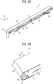
- FIG. 3A is a perspective view of a solid lubricant.
- the solid lubricant assembly 78 extends in a longitudinal direction (X-direction) of the secondary transfer belt 24 and has a thickness Lh in a thickness direction (Z-direction) orthogonal to the longitudinal direction.
- the solid lubricant assembly 78 also has a height Lt in a height direction (Y-direction) orthogonal to the longitudinal direction and the thickness direction to be able to apply the lubricant for a long time. Increasing the thickness Lh and the height Lt makes it possible to increase the volume of the lubricant and apply the lubricant for a long time.
- the solid lubricant assembly 78 includes a lubricant portion 85 that is the lubricant and a biasing portion 86 that presses the lubricant portion 85 toward the secondary transfer belt 24.
- the biasing portion 86 includes a frame 87 made of sheet metal, two pressure arms 88, and two pressure springs 89. Each of the pressure arms 88 is rotatably supported on the frame 87 and attached with one end of the pressure spring 89. Each of the pressure springs 89 is extended, and another end of each of the pressure springs 89 is attached to a pin 90 that is inserted in the frame 87. (In FIG.
- each of the two pressure arms 88 receives a tensile force from each of the pressure springs 89 and is pressed in a direction to pop out from the frame 87, as illustrated in FIG. 3A .
- FIG. 3B is a partially enlarged view of the solid lubricant assembly 78 illustrated in FIG. 3A .
- the solid lubricant assembly 78 includes end portions 80 positioned at both ends in a longitudinal direction of the solid lubricant assembly 78, a receiving face 81 that is a part of the frame 87, an upper face 85a, and a bottom face 85b.
- the end portion 80 is made of a resin having an excellent sliding characteristic and includes a boss 80a.
- the solid lubricant assembly 78 As illustrated in FIG. 2B , the solid lubricant assembly 78 is supported at its bottom face 85b by a retainer 79 and positioned at its upper face 85a by the conveyance guide 77.
- the retainer 79 is made of a sheet metal, for example, and is above the cleaning blade 73.
- the cleaning blade 73 contacts the secondary transfer belt 24 and reciprocates on the secondary transfer belt 24 while the cleaning blade 73 slides over the secondary transfer belt 24. Therefore, the retainer 79 and the cleaning blade 73 are different parts.
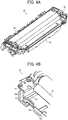
- FIG. 4A is a perspective view of the secondary transfer unit 22 that is removed some parts
- FIG. 4B is a partially enlarged view of the secondary transfer unit 22 illustrated in FIG. 4A
- FIG. 4A and FIG. 4B illustrate the secondary transfer unit 22 from which the conveyance guide 77 and the solid lubricant assembly 78 are removed.
- the retainer 79 includes a top face 79a extending in a longitudinal direction of the retainer 79, two side faces 79b positioned at both ends in the longitudinal direction of the retainer 79, and a back face 79c located on the opposite side of the lubricant application brush 76.
- the top face 79a, the two side faces 79b, and the back face 79c support the solid lubricant assembly 78 and identify its location.
- the solid lubricant assembly 78 is set on the top face 79a of the retainer 79.
- the end portions 80 of the solid lubricant assembly 78, particularly, the bosses 80a, illustrated in FIG. 3B contact the side faces 79b. This positions the solid lubricant assembly 78 in the longitudinal direction (X-direction).
- the pressure arm 88 of the solid lubricant assembly 78 contacts the back face 79c and pushes the solid lubricant assembly 78 toward the lubricant application brush 76. In this manner, the solid lubricant assembly 78 contacts the lubricant application brush 76.
- a side positioning portion 82 that is made of, for example, a stainless steel (SUS) sheet metal is disposed on the side face 79b of the retainer 79 so that the boss 80a of the solid lubricant assembly 78 and the side face 79b of the retainer 79 are more slippery.
- SUS stainless steel
- the end portion 80 may directly contact the side positioning portion 82 without the boss 80a on the end portion 80.
- a bottom positioning portion 83 including a slippery tape may be disposed on the top face 79a of the retainer 79.
- the conveyance guide 77 also positions the solid lubricant assembly 78 in the thickness direction (Z-direction).
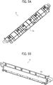
- FIG. 5A is a perspective view of the conveyance guide 77.
- FIG. 5B is a perspective view of a rear face of the conveyance guide 77.
- the conveyance guide 77 includes a guide portion 77a that contacts the recording medium and a base portion 77b that reinforces the guide portion 77a.
- the base portion 77b supports the guide portion 77a.
- the guide portion 77a is made of, for example, resin.
- the base portion 77b is made of, for example, a sheet metal.
- the guide portion 77a is attached to the base portion 77b by a snap-fit.
- FIG. 5C is a partially enlarged view of the conveyance guide 77 illustrated in FIG. 5B .
- an exit seal 92 as a seal member is attached to the base portion 77b to prevent scattering of the lubricant.
- a top positioning portion 84 formed by, for example, the slippery tape is disposed on the base portion 77b.
- the conveyance guide 77 positions the solid lubricant assembly 78 in the thickness direction (Z-direction). Specifically, the top positioning portion 84 disposed on the base portion 77b of the conveyance guide 77 contacts the solid lubricant assembly 78, and positions the solid lubricant assembly 78. Such a configuration positions the solid lubricant assembly 78 without increasing a number of parts. Because this structure does not use a lubricant case or the like, the thickness Lh (see FIG. 3A ) of the solid lubricant assembly 78 is increased, and the volume of the solid lubricant assembly 78 is certainly increased. Compared with the case of using a lubricant case or the like, this configuration can increase the volume of the lubricant.
- the top positioning portion 84 may be a protrusion instead of the slippery tape.
- FIG. 6A is a schematic diagram illustrating positioning the solid lubricant in a thickness direction (Z-direction) and a height direction (Y-direction) of the secondary transfer unit 22.
- the conveyance guide 77 (the top positioning portion 84) and the retainer 79 (the bottom positioning portion 83) identify the position in the thickness direction (Z-direction) of the solid lubricant assembly 78.
- the biasing portion 86 pushes the back face 79c of the retainer 79, the solid lubricant assembly 78 pushes the lubricant application brush 76, and the position of the solid lubricant assembly 78 in the height direction (Y-direction) is identified.
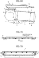
- FIG. 6B is a schematic diagram of the secondary transfer unit 22, illustrating positioning of the solid lubricant during application of the solid lubricant in the secondary transfer unit 22.
- the solid lubricant assembly 78 receives rotational torque T.
- the solid lubricant assembly 78 comes in line contact with the top positioning portion 84 of the conveyance guide 77 and the bottom positioning portion 83 of the retainer 79 at regions A in FIG. 6B , and the position of the solid lubricant assembly 78 in the thickness direction (Z-direction) is identified.
- FIG. 7A is a schematic diagram of a conveyance guide as seen from a direction of conveyance of a recording medium
- FIG. 7B is a schematic diagram illustrating the installation position of the positioning portion of the conveyance guide.
- the same reference numerals are given to the same components as those in FIGS. 5A, 5B , and 5C , and their detailed descriptions are omitted.
- the central portion of the conveyance guide 77 may be bent when the conveyance guide 77 guides the recording medium.
- the base portion 77b of the conveyance guide 77 may contact the solid lubricant assembly 78, and the position in the thickness direction (Z-direction) of the solid lubricant assembly 78 may be deviated. Therefore, preferably, the top positioning portion 84 disposed on the conveyance guide 77 forms a convex shape, and the conveyance guide 77 and the solid lubricant assembly 78 are separated by the thickness of the top positioning portion 84.
- the present embodiment uses the slippery tape as the top positioning portion 84, and the solid lubricant assembly 78 is separated from the base portion 77b of the conveyance guide 77 by the thickness of the tape. Since the base portion 77b of the conveying guide 77 is made of sheet metal, the thickness of the slippery tape is set to 0.2 mm. However, when the base portion 77b is not made of sheet metal, it is desirable to increase the thickness of the slippery tape further. That is, the thickness of the top positioning portion 84 is preferably larger than the maximum bend occurring when the conveyance guide 77 guides the recording medium.
- a pair of top positioning portions 84 provided in the conveyance guide 77 are located outside a conveyance area S of the recording medium 2 in the longitudinal direction. This is because the influence on the positional accuracy in the thickness direction (Z-direction) of the solid lubricant assembly 78 is reduced even if the conveyance guide 77 is bent.
- FIG. 8 is a side view of the secondary transfer unit. For convenience of explanation, some parts such as gears are omitted.
- a side plate 93 on the side surface of the secondary transfer unit 22 supports parts such as the secondary transfer roller 70, the lubricant application brush 76, the retainer 79, the conveyance guide 77, and the like. This configuration, in which the same side plate supports some parts, reduces a number of parts and improves the positional accuracy of parts such as the conveyance guide 77 in the secondary transfer belt 24.
- FIG. 9A is a perspective view of a variation of the conveyance guide
- FIG. 9B is a perspective view illustrating a part of the conveyance guide in FIG. 9A
- the conveyance guide 95 of the present variation has a guide portion 95a and a case portion 95b.
- the case portion 95b has a structure in which the base portion 77b illustrated in FIG. 5B and the retainer 79 illustrated in FIG. 4A are integrated into a single unit.
- the case portion 95b is a bottomed lubricant case having an opening only on one side.
- the case portion 95b also serves as a base member for reinforcing the guide portion 95a of the conveyance guide 95. Therefore, the guide member in the case is unnecessary, and the number of parts is reduced.
- FIG. 9C is a partial enlarged view of a cross-section of the conveyance guide in FIG. 9A , as seen from a direction of conveyance of the recording medium 2.
- sheet metal is drawn on the top face of the case portion 95b to form a convex top positioning portion 96.
- sheet metal is drawn in the same manner, and a convex bottom positioning portion 97 is formed.
- the solid lubricant assembly 78 may be positioned not by the slippery tape previously illustrated in FIG. 4B but by the positioning portions 96 and 97 in which the sheet metal is drawn.
- a side positioning portion 98 which is a sheet metal made of stainless steel (SUS) may be disposed.
- the side positioning portion 98 positions of the solid lubricant assembly 78 in the longitudinal direction.
- the side positioning portion 98 may be made to be slippery with the boss 80a of the solid lubricant assembly 78.
- the present disclosure is described above based on the embodiments. The present disclosure is not limited to the embodiments described above and various variations and improvements are possible. According to the embodiments described above, the solid lubricant assembly 78 applies the lubricant to the secondary transfer belt 24. Alternatively, the solid lubricant assembly 78 may apply the lubricant to the intermediate transfer belt 10. For example, although the transfer device of the present embodiments employs the intermediate transfer system, the present disclosure may be applied to a direct transfer system. The present disclosure may also be applied to a system in which a roller-shaped secondary transfer roller is used as the rotating body instead of the secondary transfer belt 24. According to the embodiments described above, the solid lubricant assembly 78 applies the lubricant to the secondary transfer belt 24.
- the solid lubricant assembly 78 may apply the lubricant to the secondary transfer roller 70.
- the secondary transfer belt 24 is not looped over the secondary transfer roller 70 and the secondary transfer roller 70 contacts the intermediate transfer belt 10. That is, the present disclosure may be applied to a transfer device including a rotating body that rotates in contact with a recording medium at a transfer position at which an image is transferred.
- the lubricant is applied from the solid lubricant assembly 78 to the secondary transfer belt 24 by the lubricant application brush 76, but the disclosure is not limited thereto.
- the solid lubricant assembly 78 may directly contact the rotating body (the secondary transfer belt 24) and apply the lubricant.
- the transfer device includes an intermediate transfer belt 10 as an image bearer, a secondary transfer belt 24 to form a transfer nip for transferring the image on the intermediate transfer belt 10 to the sheet 2 with the intermediate transfer belt 10 and rotate while contacting the sheet 2, a solid lubricant assembly 78 extending in the longitudinal direction of the secondary transfer belt 24 to apply a lubricant to the secondary transfer belt 24, and a conveyance guide 77 disposed on the upstream side of the transfer nip in the sheet 2 direction of conveyance to guide the sheet 2 conveyed toward the transfer nip, and position the solid lubricant assembly 78.
- the present disclosed aspect is not limited above.
- the present disclosure may be applied to a transfer device that includes an intermediate transfer belt 10 as an image bearer, a secondary transfer belt 24 to form a transfer nip for transferring the image on the intermediate transfer belt 10 to the sheet 2 with the intermediate transfer belt 10 and rotate while contacting the sheet 2, a solid lubricant assembly 78 extending in the longitudinal direction of the secondary transfer belt 24 to apply a lubricant to the secondary transfer belt 24, and a conveyance guide 77 disposed on the downstream side of the transfer nip in the sheet 2 direction of conveyance to guide the sheet 2 conveyed from the transfer nip, and position the solid lubricant assembly 78.
- the image forming apparatus including the transfer device of the present disclosure is not limited to a copy machine or a printer, but may be a facsimile machine or a multifunction peripheral having a plurality of these functions.
- the guide that guides the recording medium positions the solid lubricant assembly, it is possible to increase the volume of the solid lubricant more than before, without increasing the number of parts.
Landscapes
- Physics & Mathematics (AREA)
- General Physics & Mathematics (AREA)
- Engineering & Computer Science (AREA)
- Microelectronics & Electronic Packaging (AREA)
- Electrostatic Charge, Transfer And Separation In Electrography (AREA)
- Cleaning In Electrography (AREA)
Abstract
Description
- Aspects of the present disclosure relate to a transfer device and an image forming apparatus incorporating the transfer device.
- Conventional image forming apparatuses use a lubricant applying member such as a brush roller or a sponge roller, and apply a lubricant including zinc stearate or the like to a photoconductor drum or an intermediate transfer belt. Application of the lubricant prolongs the life of the photoconductor drum and the intermediate transfer belt, helps prevent hollow images in a transfer process, and increases transfer performance.
-
JP-4585237-B2 JP-2006-003537-A - However, the lubricant case accommodating the lubricant supports the lubricant and makes the lubricant smaller by an amount equivalent to the volume of the case. This limits the period during which the lubricant is applied. In addition, since the use of the lubricant case increases the number of parts, it is not preferable from the aspect of manufacturing and reliability.
- An object of the present disclosure is to provide a transfer device in which a solid lubricant is positioned without increasing the number of parts, and the volume of the solid lubricant is increased as compared with the conventional one.
- It is a general object of the present disclosure to provide an improved and useful transfer device in which the above-mentioned problems are eliminated. In order to achieve the above-mentioned object, there is provided a transfer device according to claim 1. Advantageous embodiments are defined by the dependent claims. Advantageously, the transfer device includes an image bearer, a rotatable body, a solid lubricant assembly, and a guide. The image bearer bears an image. The rotatable body forms a transfer nip with the image bearer to rotate in contact with a recording medium. At the transfer nip, the image on the image bearer is transferred onto the recording medium. The solid lubricant assembly includes a solid lubricant and extends in a longitudinal direction of the rotatable body. The solid lubricant assembly applies the solid lubricant to at least one of the rotatable body and the image bearer. The guide guides the recording medium and positions the solid lubricant assembly.
- In the transfer device of the present disclosure, because the guide that guides the recording medium positions the solid lubricant assembly, it is possible to increase the volume of the solid lubricant more than before, without increasing the number of parts.
- A more complete appreciation of the embodiments and many of the attendant advantages and features thereof can be readily obtained and understood from the following detailed description with reference to the accompanying drawings, wherein:
-
FIG. 1 is a schematic diagram illustrating a color copier employing a tandem type indirect transfer system according to an embodiment of the present disclosure; -
FIG. 2A is a top perspective view of a secondary transfer unit according to the embodiment of the present disclosure; -
FIG. 2B is a cross-sectional view illustrating a configuration example of the secondary transfer unit illustrated inFIG. 2A ; -
FIG. 3A is a top perspective view of a solid lubricant assembly; -
FIG. 3B is a partially enlarged view ofFIG. 3A ; -
FIG. 4A is a simplified perspective view of the secondary transfer unit, omitting some parts illustrated inFIG. 2A ; -
FIG. 4B is a partially enlarged view of the secondary transfer unit ofFIG. 4A ; -
FIG. 5A is a perspective view of a conveyance guide; -
FIG. 5B is a perspective view of the rear face of the conveyance guide; -
FIG. 5C is a partially enlarged view of the conveyance guide ofFIG. 5B ; -
FIG. 6A is a schematic diagram illustrating positioning of the solid lubricant assembly in a thickness direction (Z-direction) and a height direction (Y-direction) in the secondary transfer unit; -
FIG. 6B is a schematic diagram illustrating positioning of the solid lubricant assembly during application of the solid lubricant in the secondary transfer unit; -
FIG. 7A is a schematic diagram of the conveyance guide as seen from a direction of conveyance of a recording medium; -
FIG. 7B is a schematic diagram illustrating a set position of a positioning portion of the conveyance guide; -
FIG. 8 is a side view of the secondary transfer unit inFIG. 2A ; -
FIG. 9A is a perspective view of a variation of the conveyance guide; -
FIG. 9B is a perspective view illustrating a part of the conveyance guide inFIG. 9A ; and -
FIG. 9C is a partial enlarged view of a cross-section of the conveyance guide inFIG. 9A , as seen from the direction of conveyance of the recording medium. - In describing embodiments illustrated in the drawings, specific terminology is employed for the sake of clarity. However, the disclosure of this specification is not intended to be limited to the specific terminology so selected and it is to be understood that each specific element includes all technical equivalents that have a similar function, operate in a similar manner, and achieve a similar result.
- As used herein, the singular forms "a", "an", and "the" are intended to include the plural forms as well, unless the context clearly indicates otherwise.
- It is to be noted that the suffixes Y, M, C, and K attached to each reference numeral indicate only that components indicated thereby are used for forming yellow, magenta, cyan, and black images, respectively, and hereinafter may be omitted when color discrimination is not necessary.
- The configurations related to the present disclosure are described based on embodiments illustrated in the accompanied drawings from
FIGS. 1 to 9 . - Referring now to the drawings, wherein like reference numerals designate identical or corresponding parts throughout the several views thereof, and particularly to
FIG. 1 , a color copier 1 of an image forming apparatus employing electrophotography, according to an embodiment of the present disclosure is described. - Before describing the embodiment, preliminary items for facilitating an understanding of the embodiment will be described below.
- In recent years, there has been increasing demand for miniaturizing an image forming apparatus and reducing maintenance work. One approach studied in developing an image forming apparatus, particularly a transfer device, is a configuration that can be attached without increasing the number of parts and that applies a lubricant to a secondary transfer belt for a long time.
- The transfer device includes a cleaning blade for scraping off toner remaining on the transfer belt at an upstream side in a direction of rotation of the transfer belt and a conveyance guide for smoothly conveying a recording medium to a transfer nip on a downstream side in the direction of rotation of the transfer belt. The transfer device includes the lubricant and a brush for applying the lubricant to the transfer belt between the cleaning blade and the conveyance guide to apply the lubricant to a surface of the transfer belt before the transfer belt cleaned by the cleaning blade contacts the recording medium.
- However, in order to make the image forming apparatus smaller, it is desirable to narrow the space between the cleaning blade and the conveyance guide. A configuration in which the lubricant case accommodating the lubricant and the guide member supports the lubricant makes the lubricant smaller by an amount equivalent to the volume of the case. Therefore, the configuration makes it difficult to increase the period of applying the lubricant. In addition, because use of the lubricant case increases the number of parts, it is not preferable from the viewpoint of manufacturing and reliability.
- In the following embodiment, the transfer device is described in which the solid lubricant is positioned without increasing the number of parts and decreasing a volume of the solid lubricant.
-
FIG. 1 is a schematic diagram illustrating a color copier 1 employing a tandem type indirect transfer system according to the present embodiment of the present disclosure. The color copier 1 employs an intermediate transfer system, but the present disclosure is not limited to the intermediate transfer system. It is possible to apply the present disclosure to an image forming apparatus of a direct transfer system. - In
FIG. 1 , amain body 100 of the copier is on a sheet feeding table 200, ascanner 300 is on themain body 100 of the copier, and an automatic document feeder (ADF) 400 is further on thescanner 300. - The
main body 100 of the copier includes anintermediate transfer belt 10 that is an endless belt, at the center of themain body 100 of the copier. Theintermediate transfer belt 10 as an image bearer is wound around threesupport rollers FIG. 1 and is rotatable in a clockwise direction inFIG. 1 . - In
FIG. 1 , a tandemimage forming section 20 includes abelt cleaner 17 on the left side of thesecond support roller 15 for removing residual toner remaining on theintermediate transfer belt 10 after image transfer. In addition, the tandemimage forming section 20 includes fourimage forming units 18 corresponding to yellow, magenta, cyan, and black arranged along a direction of rotation of theintermediate transfer belt 10 on theintermediate transfer belt 10 stretched between thefirst support roller 14 and thesecond support roller 15. - The
image forming unit 18 is detachably provided as a process cartridge in themain body 100. Above the tandemimage forming section 20, there is anexposure device 21. On the other hand, on the opposite side of theintermediate transfer belt 10 from the tandemimage forming section 20, there is asecondary transfer unit 22. InFIG. 1 , thesecondary transfer unit 22 includes asecondary transfer belt 24, which is an endless belt, bridged between tworollers secondary transfer belt 24 is disposed to press against thethird support roller 16 via theintermediate transfer belt 10, and transfers an image on theintermediate transfer belt 10 onto asheet 2 as a recording medium. Therefore, thesecondary transfer unit 22 as the transfer device of the present disclosure includes theintermediate transfer belt 10. - A fixing
device 25 for fixing the image transferred on thesheet 2 is disposed beside thesecondary transfer unit 22. The fixingdevice 25 includes a fixingbelt 26 that is an endless belt and apressure roller 27 pressed against the fixingbelt 26. The above-describedsecondary transfer unit 22 also has a sheet conveying function for conveying thesheet 2 to which the image is transferred to the fixingdevice 25. Of course, thesecondary transfer unit 22 may be a charger that does not contact thesheet 2 or the intermediate transfer belt. When a secondary transfer charger is used, another member conveys thesheet 2. - In
FIG. 1 , a sheet 2-invertingdevice 28 that invers thesheet 2 to record the images on both sides of thesheet 2 is disposed under thesecondary transfer unit 22 and the fixingdevice 25 in parallel to the above-described tandemimage forming section 20. - When a user makes a copy using this color copier 1, the user places a document on a document table 30 of the
ADF 400. Alternatively, the user may place the document on anexposure glass 32 of thescanner 300 after lifting theADF 400 and may press the document against theexposure glass 32 by lowering theADF 400. When the user presses the start switch of the color copier 1, theADF 400 conveys the set document onto theexposure glass 32. When the document is set on theexposure glass 32, thescanner 300 immediately is driven. That is, afirst carriage 33 and asecond carriage 34 move. The light source in thefirst carriage 33 emits light, and the mirror in thefirst carriage 33 further reflects the light reflected from the document surface and leads the light to thesecond carriage 34. The mirror in thesecond carriage 34 reflects the light and leads the light to animaging lens 35. The light passing through theimaging lens 35 enters a readingsensor 36. Based on the light reflected from the document, the readingsensor 36 reads a content of the document. - When the user presses the start switch of the color copier 1, the driving motor rotates any one of the
support rollers intermediate transfer belt 10. The other two support rollers are driven by a rotation of theintermediate transfer belt 10. At the same time, the driving motor rotates the photoconductor 40 (a rotatable image bearer) in each of theimage forming units 18. A single-color image of one of yellow, magenta, cyan, and black is formed on eachphotoconductor 40. When theintermediate transfer belt 10 rotates, the single-color images are sequentially transferred, and a composite color image is formed on theintermediate transfer belt 10. Theintermediate transfer belt 10 as an image bearer bears the composite color image on its surface. - On the other hand, when the user pushes the start switch, a
feed roller 42 of the selectedsheet tray 44 in the sheet feeding table 200 rotates, and thesheet 2 is fed from one of thesheet trays 44 disposed on multi stage of apaper bank 43 in the sheet feeding table 200. Aseparation roller 45 separates the fed sheet 2s one by one and puts thesheet 2 in aconveyance passage 46. Aconveyance roller 47 conveys thesheet 2, and leads thesheet 2 to aconveyance passage 48 in themain body 100 of the copier. Thesheet 2 contacts aregistration roller 49 and stops. When the user uses a bypass tray, afeed roller 50 rotates to feed thesheet 2 on thebypass tray 51. Aseparation roller 52 separates the fed sheet 2s one by one and puts thesheet 2 in abypass conveyance passage 53. Similar to thesheet 2 led from theconveyance passage 48, thesheet 2 that enters thebypass conveyance passage 53 contacts theregistration roller 49 and stops. - When the composite color image on the
intermediate transfer belt 10 comes to the secondary transfer region between theintermediate transfer belt 10 and thesecondary transfer unit 22, theregistration roller 49 rotates to feed thesheet 2 so that thesheet 2 meets the composite color image at the secondary transfer region. Thesecondary transfer unit 22 transfers the color image from theintermediate transfer belt 10 onto thesheet 2. Thesecondary transfer unit 22 includes asecondary transfer belt 24 supported by asecondary transfer roller 70 and a drivenroller 71. Thesheet 2 on which the image is transferred is separated from the surface of thesecondary transfer belt 24 by the curvature of the drivenroller 71 at the position of the drivenroller 71 and is conveyed to aconveyance belt 58. Theconveyance belt 58 feeds thesheet 2 toward the fixingdevice 25. The fixingdevice 25 applies heat and pressure to thesheet 2 fed from theconveyance belt 58, and fixes the transferred image on thesheet 2. A switchingclaw 55 is disposed downstream of the fixingdevice 25 in a sheet direction of conveyance. The switchingclaw 55 switches the sheet direction of conveyance and guides thesheet 2 to thedischarge roller 56 or the sheet-invertingdevice 28. Thesheet 2 guided to thedischarge roller 56 is discharged to the outside of the image forming apparatus and stacked on anoutput tray 57. Thesheet 2 guided to the sheet-invertingdevice 28 is inverted by the sheet-invertingdevice 28 and conveyed again to the secondary transfer region. An image is also recorded on the back surface of theinverted sheet 2. After that, thesheet 2 is guided to thedischarge roller 56, and discharged onto theoutput tray 57. - After the image is transferred from the
intermediate transfer belt 10 onto thesheet 2, thebelt cleaner 17 removes residual toner remaining on theintermediate transfer belt 10 after image transfer. Thus, the tandemimage forming section 20 enables the next image formation. - The
intermediate transfer belt 10 is constructed of a single layer or a plurality of layers including polyvinylidene fluoride (PVDF), ethylene tetrafluoroethylene (ETFE) copolymer, polyimide (PI), polycarbonate (PC), and the like. The layers is/are adjusted such that a conductive material such as carbon black is dispersed and its volume resistivity is 108 to 1012 Ω·cm and its surface resistivity is 109 to 1013 Ω·cm. If necessary, theintermediate transfer belt 10 may have a release layer coated on its surface. Materials used for the coating include ethylene-tetrafluoroethylene copolymer (ETFE), polytetrafluoroethylene (PTFE), vinylidene fluoride (PVDF), perfluoroalkoxy fluorine resin (PEA), Ethylene-hexafluoropropylene copolymer (FEP), vinyl fluoride (PVF), etc., but is not limited thereto. - The
intermediate transfer belt 10 is manufactured through a casting process, a centrifugal casting process, and the like. If necessary, the surface of theintermediate transfer belt 10 may be polished. - In the measurement of the volume resistivity and the surface resistivity, a high-resistivity meter (Hiresta IP made by Mitsubishi Chemical Corporation) connected with an HRS probe (inner electrode diameter 5.9 mm, ring electrode inner diameter 11 mm) is used. The volume resistivity is measured as a value measured after 10 seconds after a voltage of 100 V is applied between the front and back of the
intermediate transfer belt 10. When the surface resistivity is measured, the voltage applied to the intermediate transfer belt is set 500 V. - The transfer roller is made by applying a foaming resin agent to a cored bar made of metal (iron, stainless steel, aluminum, etc.). The thickness of the foamed resin agent is 2 mm to 10 mm, but it is not limited thereto.
- Subsequently, a configuration of the
secondary transfer unit 22, which is a characteristic part of the present disclosure, is described.FIG. 2A is a top perspective view of a secondary transfer unit according to the embodiment of the present disclosure.FIG. 2B is a cross-sectional view illustrating a configuration example of the secondary transfer unit. - As illustrated in
FIG. 2B , thesecondary transfer belt 24 is wound around thesecondary transfer roller 70 and the drivenroller 71, and is rotated counterclockwise inFIG. 2B . Thesecondary transfer unit 22 includes abrush 72 for removing paper dust, acleaning blade 73, alubricant application brush 76 that is a lubricant applicator, and aconveyance guide 77 in the secondary transfer unit, all of which are arranged in that order upstream to downstream in the direction of rotation of thesecondary transfer roller 70. - As illustrated in
FIG. 2B , anintermediate transfer belt 10 is disposed above thesecondary transfer unit 22. Theintermediate transfer belt 10 is wound around a third support roller (a secondary transfer opposite roller) 16 and a push downroller 19, respectively. Thesecondary transfer roller 70 is pushed toward the third support roller (the secondary transfer opposite roller) 16 by a spring or the like. A transfer nip N to transfer a toner image borne on theintermediate transfer belt 10 onto thesheet 2 is formed between thesecondary transfer belt 24 supported by thesecondary transfer roller 70 and theintermediate transfer belt 10 supported by the third support roller (secondary transfer opposite roller 16). - The push down
roller 19 pushes theintermediate transfer belt 10 downward as illustrated inFIG. 2B at a position upstream of the transfer nip N in the direction of rotation of theintermediate transfer belt 10. A guide plate (an intermediate transfer side conveyance guide) 59 on the intermediate transfer guide side and theconveyance guide 77 are provided at a position on an upstream side of the transfer nip N in a sheet direction of conveyance. The conveyance guide 77 contacts the back surface of thesheet 2, and theguide plate 59 on the intermediate transfer guide side contacts the front surface of thesheet 2. Each of theconveyance guide 77 and theguide plate 59 guides thesheet 2 toward the transfer nip N. In the present embodiment, theguide plate 59 on the intermediate transfer guide side and theconveyance guide 77 guide thesheet 2 so that the leading edge of thesheet 2 contacts a surface of thesecondary transfer belt 24 at a position on the upstream side from the transfer nip N in the sheet direction of conveyance (inFIG. 2B ). - How to guide the
sheet 2 is not limited to this. For example, theguide plate 59 on the intermediate transfer guide side and theconveyance guide 77 may guide thesheet 2 so that the leading edge of thesheet 2 contacts a surface of theintermediate transfer belt 10 at a position on the upstream side from the transfer nip N in the sheet direction of conveyance (inFIG. 2B ). - Alternatively, either one of the
guide plate 59 on the intermediate transfer guide side and theconveyance guide 77 may guide the leading edge of thesheet 2, and the other of theguide plate 59 on the intermediate transfer guide side and theconveyance guide 77 or both may guide a portion other than the leading edge of thesheet 2. - A conveyance posture (conveyance position) of the
sheet 2 in the image forming apparatus differs depending on stiffness and thickness of thesheet 2. Theconveyance guide 77 may be arranged so that only thethin sheet 2 or the curledsheet 2 is guided by theconveyance guide 77. - The
brush 72 for removing the paper dust is rotatable in a clockwise direction inFIG. 2B , and removes dust adhering to the surface of thesecondary transfer belt 24. Thecleaning blade 73 contacts the surface of thesecondary transfer belt 24 to scrape off the toner adhering to thesecondary transfer belt 24. The removed waste toner falls into awaste toner bottle 74 disposed under thecleaning blade 73, and a conveyingscrew 75 conveys the removed waste toner. - The
lubricant application brush 76, disposed on the downstream side in the direction of rotation of thesecondary transfer roller 70 from thecleaning blade 73 is between thesolid lubricant assembly 78 and the secondary transfer belt 24 (the secondary transfer roller 70), rotates and rubs both of them. That is, thelubricant application brush 76 applies thesolid lubricant assembly 78 to thesecondary transfer belt 24. The lubricant reduces the friction coefficient of the surface of thesecondary transfer belt 24 and prevents thecleaning blade 73 from turning. Alternatively, instead of thelubricant application brush 76, a sponge roller may be used. These lubricant applicators enable to apply the lubricant uniformly to the secondary transfer belt. - The
solid lubricant assembly 78 extends in the longitudinal direction of thesecondary transfer belt 24 and has a constant height in the height direction orthogonal to the longitudinal direction thereof. Theconveyance guide 77 is used for smoothly guiding the recording medium to the transfer nip (for example, inFIG. 1 , thethird support roller 16 and thesecondary transfer belt 24 form the transfer nip N). - In order to apply the lubricant after the dust and the residual toner are removed from the
secondary transfer belt 24, the parts from thebrush 72 for removing the paper dust to theconveyance guide 77 are disposed in the described order around thesecondary transfer belt 24. Since the lubricant is applied after the surface of thesecondary transfer belt 24 is cleaned, the lubricant is uniformly applied to the surface of thesecondary transfer belt 24. Therefore, the friction coefficient of the surface of thesecondary transfer belt 24 decreases uniformly, which reliably prevents the turning of thecleaning blade 73. This extends a life of thesecondary transfer belt 24 and the secondary transfer unit. - As described above, it is desirable that the space between the
cleaning blade 73 and theconveyance guide 77 be narrowed in the image forming apparatus in which miniaturization is desired. The structure that supports the lubricant with the lubricant case requires improvement because the structure reduces the capacity of the lubricant and increases the number of components such as the lubricant case. In the present embodiment, the lubricant is not supported by the lubricant case. The present embodiment employs a configuration in which thesolid lubricant assembly 78 is supported and positioned by using existing components, in particular, theconveyance guide 77. The configuration is described in detail below. -
FIG. 3A is a perspective view of a solid lubricant. As illustrated inFIG. 3A , to apply the lubricant to a conveyance area of therecording medium 2 on thesecondary transfer belt 24, thesolid lubricant assembly 78 extends in a longitudinal direction (X-direction) of thesecondary transfer belt 24 and has a thickness Lh in a thickness direction (Z-direction) orthogonal to the longitudinal direction. Thesolid lubricant assembly 78 also has a height Lt in a height direction (Y-direction) orthogonal to the longitudinal direction and the thickness direction to be able to apply the lubricant for a long time. Increasing the thickness Lh and the height Lt makes it possible to increase the volume of the lubricant and apply the lubricant for a long time. - The
solid lubricant assembly 78 includes alubricant portion 85 that is the lubricant and a biasingportion 86 that presses thelubricant portion 85 toward thesecondary transfer belt 24. The biasingportion 86 includes aframe 87 made of sheet metal, twopressure arms 88, and two pressure springs 89. Each of thepressure arms 88 is rotatably supported on theframe 87 and attached with one end of thepressure spring 89. Each of the pressure springs 89 is extended, and another end of each of the pressure springs 89 is attached to apin 90 that is inserted in theframe 87. (InFIG. 3A , the pressure springs 89 are not attached to thepin 90.) Therefore, each of the twopressure arms 88 receives a tensile force from each of the pressure springs 89 and is pressed in a direction to pop out from theframe 87, as illustrated inFIG. 3A . - There are multiple insert holes 91 for the
pin 90 in theframe 87. Changing a position of thepin 90 enables adjusting the tensile force of the pressure springs 89 that act thepressure arms 88. -
FIG. 3B is a partially enlarged view of thesolid lubricant assembly 78 illustrated inFIG. 3A . For convenience of explanation, only one end of thesolid lubricant assembly 78 is illustrated inFIG. 3B . Another end of thesolid lubricant assembly 78 has the same structure. As illustrated inFIG. 3B , thesolid lubricant assembly 78 includesend portions 80 positioned at both ends in a longitudinal direction of thesolid lubricant assembly 78, a receivingface 81 that is a part of theframe 87, anupper face 85a, and abottom face 85b. Theend portion 80 is made of a resin having an excellent sliding characteristic and includes aboss 80a. - Referring back to
FIG. 2B , a description is provided of the configuration of thesolid lubricant assembly 78. As illustrated inFIG. 2B , thesolid lubricant assembly 78 is supported at itsbottom face 85b by aretainer 79 and positioned at itsupper face 85a by theconveyance guide 77. Theretainer 79 is made of a sheet metal, for example, and is above thecleaning blade 73. Thecleaning blade 73 contacts thesecondary transfer belt 24 and reciprocates on thesecondary transfer belt 24 while thecleaning blade 73 slides over thesecondary transfer belt 24. Therefore, theretainer 79 and thecleaning blade 73 are different parts. -
FIG. 4A is a perspective view of thesecondary transfer unit 22 that is removed some parts, andFIG. 4B is a partially enlarged view of thesecondary transfer unit 22 illustrated inFIG. 4A. FIG. 4A and FIG. 4B illustrate thesecondary transfer unit 22 from which theconveyance guide 77 and thesolid lubricant assembly 78 are removed. As illustrated inFIG. 4B , theretainer 79 includes atop face 79a extending in a longitudinal direction of theretainer 79, two side faces 79b positioned at both ends in the longitudinal direction of theretainer 79, and aback face 79c located on the opposite side of thelubricant application brush 76. In theretainer 79, thetop face 79a, the two side faces 79b, and theback face 79c support thesolid lubricant assembly 78 and identify its location. - The
solid lubricant assembly 78 is set on thetop face 79a of theretainer 79. Theend portions 80 of thesolid lubricant assembly 78, particularly, thebosses 80a, illustrated inFIG. 3B , contact the side faces 79b. This positions thesolid lubricant assembly 78 in the longitudinal direction (X-direction). Thepressure arm 88 of thesolid lubricant assembly 78 contacts theback face 79c and pushes thesolid lubricant assembly 78 toward thelubricant application brush 76. In this manner, thesolid lubricant assembly 78 contacts thelubricant application brush 76. - Preferably, a
side positioning portion 82 that is made of, for example, a stainless steel (SUS) sheet metal is disposed on theside face 79b of theretainer 79 so that theboss 80a of thesolid lubricant assembly 78 and theside face 79b of theretainer 79 are more slippery. This prevents one-side contact of theend portions 80 caused by abrasion and improves reliability. Theend portion 80 may directly contact theside positioning portion 82 without theboss 80a on theend portion 80. Alternatively, for example, abottom positioning portion 83 including a slippery tape may be disposed on thetop face 79a of theretainer 79. - Subsequently, the
conveyance guide 77 is described. Theconveyance guide 77 also positions thesolid lubricant assembly 78 in the thickness direction (Z-direction). -
FIG. 5A is a perspective view of theconveyance guide 77.FIG. 5B is a perspective view of a rear face of theconveyance guide 77. As illustrated inFIGS. 5A and 5B , theconveyance guide 77 includes aguide portion 77a that contacts the recording medium and abase portion 77b that reinforces theguide portion 77a. Thebase portion 77b supports theguide portion 77a. Theguide portion 77a is made of, for example, resin. Thebase portion 77b is made of, for example, a sheet metal. Theguide portion 77a is attached to thebase portion 77b by a snap-fit. -
FIG. 5C is a partially enlarged view of theconveyance guide 77 illustrated inFIG. 5B . As illustrated inFIG. 5C , anexit seal 92 as a seal member is attached to thebase portion 77b to prevent scattering of the lubricant. Additionally, atop positioning portion 84 formed by, for example, the slippery tape is disposed on thebase portion 77b. - As illustrated in
FIG. 2B , theconveyance guide 77 positions thesolid lubricant assembly 78 in the thickness direction (Z-direction). Specifically, thetop positioning portion 84 disposed on thebase portion 77b of theconveyance guide 77 contacts thesolid lubricant assembly 78, and positions thesolid lubricant assembly 78. Such a configuration positions thesolid lubricant assembly 78 without increasing a number of parts. Because this structure does not use a lubricant case or the like, the thickness Lh (seeFIG. 3A ) of thesolid lubricant assembly 78 is increased, and the volume of thesolid lubricant assembly 78 is certainly increased. Compared with the case of using a lubricant case or the like, this configuration can increase the volume of the lubricant. Thetop positioning portion 84 may be a protrusion instead of the slippery tape. - Subsequently, a description is given below of the
secondary transfer unit 22 of the present embodiment in which how the position of thesolid lubricant assembly 78 is identified when thelubricant application brush 76 is at rest and when thelubricant application brush 76 rotates to apply the lubricant. -
FIG. 6A is a schematic diagram illustrating positioning the solid lubricant in a thickness direction (Z-direction) and a height direction (Y-direction) of thesecondary transfer unit 22. As illustrated inFIG. 6A , the conveyance guide 77 (the top positioning portion 84) and the retainer 79 (the bottom positioning portion 83) identify the position in the thickness direction (Z-direction) of thesolid lubricant assembly 78. With respect to the position in the height direction (Y-direction), the biasingportion 86 pushes theback face 79c of theretainer 79, thesolid lubricant assembly 78 pushes thelubricant application brush 76, and the position of thesolid lubricant assembly 78 in the height direction (Y-direction) is identified. -
FIG. 6B is a schematic diagram of thesecondary transfer unit 22, illustrating positioning of the solid lubricant during application of the solid lubricant in thesecondary transfer unit 22. As illustrated inFIG. 6B , as thelubricant application brush 76 rotates clockwise inFIG. 6B , thesolid lubricant assembly 78 receives rotational torque T. In this case, thesolid lubricant assembly 78 comes in line contact with thetop positioning portion 84 of theconveyance guide 77 and thebottom positioning portion 83 of theretainer 79 at regions A inFIG. 6B , and the position of thesolid lubricant assembly 78 in the thickness direction (Z-direction) is identified. Even when the volume of thelubricant portion 85 of thesolid lubricant assembly 78 decreases, and thesolid lubricant assembly 78 moves in the Y-direction, the position of thesolid lubricant assembly 78 in the thickness direction (Z-direction) is identified. Therefore, the position of thesolid lubricant assembly 78 is maintained for a long time, and the lubricant is applied without replenishing the lubricant by the field technician. - Subsequently, the advantages of the present disclosure are described.
-
FIG. 7A is a schematic diagram of a conveyance guide as seen from a direction of conveyance of a recording medium, andFIG. 7B is a schematic diagram illustrating the installation position of the positioning portion of the conveyance guide. InFIGS. 7A and 7B , the same reference numerals are given to the same components as those inFIGS. 5A, 5B , and5C , and their detailed descriptions are omitted. - As illustrated in
FIG. 7A , the central portion of theconveyance guide 77 may be bent when theconveyance guide 77 guides the recording medium. When theconveyance guide 77 is bent, thebase portion 77b of theconveyance guide 77 may contact thesolid lubricant assembly 78, and the position in the thickness direction (Z-direction) of thesolid lubricant assembly 78 may be deviated. Therefore, preferably, thetop positioning portion 84 disposed on theconveyance guide 77 forms a convex shape, and theconveyance guide 77 and thesolid lubricant assembly 78 are separated by the thickness of thetop positioning portion 84. The present embodiment uses the slippery tape as thetop positioning portion 84, and thesolid lubricant assembly 78 is separated from thebase portion 77b of theconveyance guide 77 by the thickness of the tape. Since thebase portion 77b of the conveyingguide 77 is made of sheet metal, the thickness of the slippery tape is set to 0.2 mm. However, when thebase portion 77b is not made of sheet metal, it is desirable to increase the thickness of the slippery tape further. That is, the thickness of thetop positioning portion 84 is preferably larger than the maximum bend occurring when theconveyance guide 77 guides the recording medium. - Further, as illustrated in
FIG. 7B , it is preferable that a pair oftop positioning portions 84 provided in theconveyance guide 77 are located outside a conveyance area S of therecording medium 2 in the longitudinal direction. This is because the influence on the positional accuracy in the thickness direction (Z-direction) of thesolid lubricant assembly 78 is reduced even if theconveyance guide 77 is bent. -
FIG. 8 is a side view of the secondary transfer unit. For convenience of explanation, some parts such as gears are omitted. As illustrated inFIG. 8 , preferably, aside plate 93 on the side surface of thesecondary transfer unit 22 supports parts such as thesecondary transfer roller 70, thelubricant application brush 76, theretainer 79, theconveyance guide 77, and the like. This configuration, in which the same side plate supports some parts, reduces a number of parts and improves the positional accuracy of parts such as theconveyance guide 77 in thesecondary transfer belt 24. -
FIG. 9A is a perspective view of a variation of the conveyance guide, andFIG. 9B is a perspective view illustrating a part of the conveyance guide inFIG. 9A . As illustrated inFIG. 9 , theconveyance guide 95 of the present variation has aguide portion 95a and acase portion 95b. Thecase portion 95b has a structure in which thebase portion 77b illustrated inFIG. 5B and theretainer 79 illustrated inFIG. 4A are integrated into a single unit. - The
case portion 95b is a bottomed lubricant case having an opening only on one side. Thecase portion 95b also serves as a base member for reinforcing theguide portion 95a of theconveyance guide 95. Therefore, the guide member in the case is unnecessary, and the number of parts is reduced. -
FIG. 9C is a partial enlarged view of a cross-section of the conveyance guide inFIG. 9A , as seen from a direction of conveyance of therecording medium 2. As illustrated inFIG. 9C , sheet metal is drawn on the top face of thecase portion 95b to form a convextop positioning portion 96. Similarly, on the bottom face of thecase portion 95b, sheet metal is drawn in the same manner, and a convexbottom positioning portion 97 is formed. In this way, thesolid lubricant assembly 78 may be positioned not by the slippery tape previously illustrated inFIG. 4B but by thepositioning portions case portion 95b, for example, aside positioning portion 98 which is a sheet metal made of stainless steel (SUS) may be disposed. Theside positioning portion 98 positions of thesolid lubricant assembly 78 in the longitudinal direction. Theside positioning portion 98 may be made to be slippery with theboss 80a of thesolid lubricant assembly 78. - The present disclosure is described above based on the embodiments. The present disclosure is not limited to the embodiments described above and various variations and improvements are possible. According to the embodiments described above, the
solid lubricant assembly 78 applies the lubricant to thesecondary transfer belt 24. Alternatively, thesolid lubricant assembly 78 may apply the lubricant to theintermediate transfer belt 10. For example, although the transfer device of the present embodiments employs the intermediate transfer system, the present disclosure may be applied to a direct transfer system. The present disclosure may also be applied to a system in which a roller-shaped secondary transfer roller is used as the rotating body instead of thesecondary transfer belt 24. According to the embodiments described above, thesolid lubricant assembly 78 applies the lubricant to thesecondary transfer belt 24. Alternatively, thesolid lubricant assembly 78 may apply the lubricant to thesecondary transfer roller 70. In this case, thesecondary transfer belt 24 is not looped over thesecondary transfer roller 70 and thesecondary transfer roller 70 contacts theintermediate transfer belt 10. That is, the present disclosure may be applied to a transfer device including a rotating body that rotates in contact with a recording medium at a transfer position at which an image is transferred. - Further, in the present embodiments, the lubricant is applied from the
solid lubricant assembly 78 to thesecondary transfer belt 24 by thelubricant application brush 76, but the disclosure is not limited thereto. Thesolid lubricant assembly 78 may directly contact the rotating body (the secondary transfer belt 24) and apply the lubricant. - Further, in the above-described embodiment and variation, the transfer device includes an
intermediate transfer belt 10 as an image bearer, asecondary transfer belt 24 to form a transfer nip for transferring the image on theintermediate transfer belt 10 to thesheet 2 with theintermediate transfer belt 10 and rotate while contacting thesheet 2, asolid lubricant assembly 78 extending in the longitudinal direction of thesecondary transfer belt 24 to apply a lubricant to thesecondary transfer belt 24, and aconveyance guide 77 disposed on the upstream side of the transfer nip in thesheet 2 direction of conveyance to guide thesheet 2 conveyed toward the transfer nip, and position thesolid lubricant assembly 78. However, the present disclosed aspect is not limited above. - The present disclosure may be applied to a transfer device that includes an
intermediate transfer belt 10 as an image bearer, asecondary transfer belt 24 to form a transfer nip for transferring the image on theintermediate transfer belt 10 to thesheet 2 with theintermediate transfer belt 10 and rotate while contacting thesheet 2, asolid lubricant assembly 78 extending in the longitudinal direction of thesecondary transfer belt 24 to apply a lubricant to thesecondary transfer belt 24, and aconveyance guide 77 disposed on the downstream side of the transfer nip in thesheet 2 direction of conveyance to guide thesheet 2 conveyed from the transfer nip, and position thesolid lubricant assembly 78. - Furthermore, the image forming apparatus including the transfer device of the present disclosure is not limited to a copy machine or a printer, but may be a facsimile machine or a multifunction peripheral having a plurality of these functions.
- In the above described transfer device, because the guide that guides the recording medium positions the solid lubricant assembly, it is possible to increase the volume of the solid lubricant more than before, without increasing the number of parts.
Claims (14)
- A transfer device (22) comprising:an image bearer (10) to bear an image;a rotatable body (24) that forms a transfer nip (N) with the image bearer (10) to rotate in contact with a recording medium (2), the transfer nip (N) where the image on the image bearer (10) is transferred onto the recording medium (2),a solid lubricant assembly (78) including a solid lubricant (85) and extending in a longitudinal direction of the rotatable body (24), the solid lubricant assembly (78) to apply the solid lubricant (85) to at least one of the rotatable body (24) and the image bearer (10); anda guide (77) to guide the recording medium (2) and position the solid lubricant assembly (78).
- The transfer device (22) according to claim 1,
wherein the guide (77) includes a positioning portion (84; 96) to position the solid lubricant assembly (78) in a thickness direction orthogonal to a longitudinal direction of the solid lubricant assembly (78). - The transfer device (22) according to claim 2,
wherein the positioning portion (84; 96) on the guide (77) is disposed outside a conveyance area of the recording medium (2) in the longitudinal direction of the solid lubricant assembly (78). - The transfer device (22) according to claim 2 or 3,
wherein the positioning portion (84; 96) has a convex shape, and a thickness of the positioning portion (84; 96) is larger than a maximum bend occurring when the guide (77) guides the recording medium (2) being conveyed. - The transfer device (22) according to any one of claims 1 to 4,
wherein the guide (77) includes:a guide portion (77a) to guide the recording medium (2); anda base portion (77b) to reinforce the guide portion (77a). - The transfer device (22) according to any one of claims 1 to 5, further comprising:a retainer (79) that holds and positions both ends (80) of the solid lubricant assembly (78) in a longitudinal direction of the solid lubricant assembly (78) and one face (85b) of the solid lubricant assembly (78) in a thickness direction of the solid lubricant assembly (78),wherein the guide (77) positions another face (85a) of the solid lubricant assembly (78) in the thickness direction of the solid lubricant assembly (78).
- The transfer device (22) according to any one of claims 1 to 4, further comprising:a retainer (79) that holds and positions both ends (80) of the solid lubricant assembly (78) in a longitudinal direction of the solid lubricant assembly (78) and one face (85b) of the solid lubricant assembly (78) in a thickness direction of the solid lubricant assembly (78),wherein the guide (77) includes:a guide portion (77a) to guide the recording medium (2); anda base portion (77b) to reinforce the guide portion (77a), and positions another face (85a) of the solid lubricant assembly (78) in the thickness direction of the solid lubricant assembly (78), andwherein the base portion (77b) and the retainer (79) form a single integrated unit (95b).
- The transfer device (22) according to any one of claims 1 to 7, further comprising:a cleaning blade (73) to remove toner adhering to a surface of the rotatable body (24) after the image is transferred from the surface of the rotatable body (24),wherein the solid lubricant assembly (78) is disposed between the cleaning blade (73) and the guide (77).
- The transfer device (22) according to any one of claims 1 to 8, further comprising:a biasing part (86) to press the solid lubricant assembly (78) against the rotatable body (24).
- The transfer device (22) according to any one of claims 1 to 8, further comprising:a lubricant applicator (76) to apply the solid lubricant assembly (78) to the rotatable body (24).
- The transfer device (22) according to any one of claims 1 to 9, further comprising:a secondary transfer roller (70) to support the rotatable body (24); and (77),at least one side plate (93) to support the secondary transfer roller (70) and the guide (77),wherein the rotatable body (24) includes a transfer belt (24) supported by the secondary transfer roller (70).
- The transfer device (22) according to claim 1,
wherein the rotatable body (24) includes a transfer roller (70). - The transfer device (22) according to claim 1,
wherein the image bearer (10) includes an intermediate transfer belt (10). - An image forming apparatus (1), comprising the transfer device (22) according to any one of claims 1 to 13.
Applications Claiming Priority (1)
| Application Number | Priority Date | Filing Date | Title |
|---|---|---|---|
| JP2016236581A JP6888285B2 (en) | 2016-12-06 | 2016-12-06 | Transfer device and image forming device |
Publications (2)
| Publication Number | Publication Date |
|---|---|
| EP3333636A1 true EP3333636A1 (en) | 2018-06-13 |
| EP3333636B1 EP3333636B1 (en) | 2019-06-12 |
Family
ID=60629459
Family Applications (1)
| Application Number | Title | Priority Date | Filing Date |
|---|---|---|---|
| EP17205414.0A Not-in-force EP3333636B1 (en) | 2016-12-06 | 2017-12-05 | Transfer device and image forming apparatus incorporating same |
Country Status (3)
| Country | Link |
|---|---|
| US (1) | US10114331B2 (en) |
| EP (1) | EP3333636B1 (en) |
| JP (1) | JP6888285B2 (en) |
Families Citing this family (3)
| Publication number | Priority date | Publication date | Assignee | Title |
|---|---|---|---|---|
| US10558148B2 (en) | 2018-03-30 | 2020-02-11 | Ricoh Company, Ltd. | Belt device and image forming apparatus incorporating same |
| JP7419828B2 (en) | 2020-01-17 | 2024-01-23 | 株式会社リコー | Roller unit, belt device, and image forming device |
| US11494602B2 (en) | 2020-09-15 | 2022-11-08 | Ricoh Company, Ltd. | Image forming apparatus |
Citations (5)
| Publication number | Priority date | Publication date | Assignee | Title |
|---|---|---|---|---|
| JPH11133762A (en) * | 1997-10-27 | 1999-05-21 | Ricoh Co Ltd | Image forming device |
| JP2002351258A (en) * | 2001-05-28 | 2002-12-06 | Ricoh Co Ltd | Lubricant, lubricant application device, and image forming device |
| JP2006003537A (en) | 2004-06-16 | 2006-01-05 | Ricoh Co Ltd | Lubricant coating apparatus, process cartridge, and image forming apparatus |
| US20080124155A1 (en) * | 2006-11-27 | 2008-05-29 | Ryuuichi Mimbu | Transferring device having two devices for cleaning a transferring member, and image forming apparatus |
| EP2367073A2 (en) * | 2010-03-17 | 2011-09-21 | Ricoh Company, Ltd. | Lubricant applying device, image forming apparatus, process unit, and solid lubricant |
Family Cites Families (23)
| Publication number | Priority date | Publication date | Assignee | Title |
|---|---|---|---|---|
| JP5005310B2 (en) * | 2006-10-05 | 2012-08-22 | 株式会社リコー | Lubricant coating apparatus, process cartridge, and image forming apparatus |
| US8000632B2 (en) * | 2007-05-25 | 2011-08-16 | Kabushiki Kaisha Toshiba | Image forming apparatus and image forming method |
| JP2009042295A (en) | 2007-08-06 | 2009-02-26 | Ricoh Co Ltd | Cleaning device, process cartridge, and image forming apparatus |
| JP2010139603A (en) * | 2008-12-10 | 2010-06-24 | Ricoh Co Ltd | Image forming apparatus |
| JP5245969B2 (en) * | 2009-03-25 | 2013-07-24 | 株式会社リコー | Cleaning device and image forming apparatus |
| JP5493608B2 (en) | 2009-09-07 | 2014-05-14 | 株式会社リコー | Transfer device and image forming apparatus |
| JP5522510B2 (en) | 2009-09-15 | 2014-06-18 | 株式会社リコー | Transfer device and image forming apparatus equipped with the transfer device |
| JP2011248270A (en) * | 2010-05-31 | 2011-12-08 | Ricoh Co Ltd | Image forming device |
| JP5915085B2 (en) | 2010-11-15 | 2016-05-11 | 株式会社リコー | Transfer device and image forming apparatus using the same |
| JP5310795B2 (en) * | 2011-06-22 | 2013-10-09 | 株式会社リコー | Lubricant coating apparatus, process cartridge, and image forming apparatus |
| JP6187857B2 (en) | 2013-02-14 | 2017-08-30 | 株式会社リコー | Transfer device and image forming apparatus |
| JP2016027353A (en) | 2013-08-22 | 2016-02-18 | 株式会社リコー | Image forming apparatus |
| JP2015161941A (en) * | 2014-02-28 | 2015-09-07 | 株式会社リコー | Belt device and image forming apparatus having the same |
| US9547249B2 (en) | 2014-09-26 | 2017-01-17 | Ricoh Company, Ltd. | Image forming apparatus |
| US9395658B2 (en) | 2014-12-09 | 2016-07-19 | Ricoh Company, Ltd. | Image forming apparatus |
| US9690246B2 (en) | 2014-12-15 | 2017-06-27 | Ricoh Company, Ltd. | Image forming apparatus including contact members disposed side by side at positions opposing a guide unit |
| US9740156B2 (en) | 2015-03-19 | 2017-08-22 | Ricoh Company, Ltd. | Image forming apparatus that adjusts a transfer bias according to surface properties of a transfer target |
| JP6493802B2 (en) | 2015-07-07 | 2019-04-03 | 株式会社リコー | Transfer device and image forming apparatus |
| JP2017067803A (en) | 2015-09-28 | 2017-04-06 | 株式会社リコー | Belt device and image forming apparatus |
| JP2017111233A (en) | 2015-12-15 | 2017-06-22 | 株式会社リコー | Roller member and image forming apparatus |
| US10234794B2 (en) | 2015-12-15 | 2019-03-19 | Ricoh Company, Ltd. | Roller member and image forming apparatus including the roller member |
| US10185255B2 (en) | 2016-02-15 | 2019-01-22 | Ricoh Company, Ltd. | Image forming apparatus and image forming method for controlling a secondary transfer bias according to recording sheet type |
| US10281848B2 (en) | 2016-02-15 | 2019-05-07 | Ricoh Company, Ltd. | Image forming apparatus and image forming method |
-
2016
- 2016-12-06 JP JP2016236581A patent/JP6888285B2/en active Active
-
2017
- 2017-12-05 EP EP17205414.0A patent/EP3333636B1/en not_active Not-in-force
- 2017-12-05 US US15/831,566 patent/US10114331B2/en not_active Expired - Fee Related
Patent Citations (6)
| Publication number | Priority date | Publication date | Assignee | Title |
|---|---|---|---|---|
| JPH11133762A (en) * | 1997-10-27 | 1999-05-21 | Ricoh Co Ltd | Image forming device |
| JP2002351258A (en) * | 2001-05-28 | 2002-12-06 | Ricoh Co Ltd | Lubricant, lubricant application device, and image forming device |
| JP2006003537A (en) | 2004-06-16 | 2006-01-05 | Ricoh Co Ltd | Lubricant coating apparatus, process cartridge, and image forming apparatus |
| JP4585237B2 (en) | 2004-06-16 | 2010-11-24 | 株式会社リコー | Lubricant coating apparatus, process cartridge, and image forming apparatus |
| US20080124155A1 (en) * | 2006-11-27 | 2008-05-29 | Ryuuichi Mimbu | Transferring device having two devices for cleaning a transferring member, and image forming apparatus |
| EP2367073A2 (en) * | 2010-03-17 | 2011-09-21 | Ricoh Company, Ltd. | Lubricant applying device, image forming apparatus, process unit, and solid lubricant |
Also Published As
| Publication number | Publication date |
|---|---|
| EP3333636B1 (en) | 2019-06-12 |
| JP2018092057A (en) | 2018-06-14 |
| JP6888285B2 (en) | 2021-06-16 |
| US20180157209A1 (en) | 2018-06-07 |
| US10114331B2 (en) | 2018-10-30 |
Similar Documents
| Publication | Publication Date | Title |
|---|---|---|
| US10082751B2 (en) | Fixing device and image forming apparatus | |
| US9846397B2 (en) | Fixing device including a supplementary thermal conductor and image forming apparatus incorporating same | |
| US9164435B2 (en) | Fixing device and image forming apparatus | |
| US9052652B2 (en) | Fixing device including a friction reducer and an image forming apparatus including the fixing device | |
| US9575447B2 (en) | Fixing device and image forming apparatus | |
| US6636709B2 (en) | Fixing device having temperature detecting member and image forming apparatus using said fixing device | |
| US8515312B2 (en) | Fixing device and image forming apparatus including same | |
| US9740147B2 (en) | Separator, fixing device, and image forming apparatus | |
| US10962908B2 (en) | Heating device, fixing device, and image forming apparatus | |
| US8897688B2 (en) | Fixing device and image forming apparatus | |
| US9869952B2 (en) | Fixing device and image forming apparatus including a friction reducer including a lubricant | |
| US10795289B2 (en) | Fixing device and image forming apparatus incorporating the same | |
| US8532553B2 (en) | Fixing device and image forming apparatus including same | |
| US12393141B2 (en) | Fixing device and image forming apparatus | |
| CN101344746A (en) | Belt device and imaging equipment | |
| US8989641B2 (en) | Fixing device with mechanism capable of minimizing glossy streaks and stain on recording medium and image forming apparatus incorporating same | |
| US9268276B2 (en) | Fixing device and image forming apparatus that include a separator disposed downstream from a fixing nip | |
| EP3333636B1 (en) | Transfer device and image forming apparatus incorporating same | |
| US20160363907A1 (en) | Image forming apparatus | |
| US11009817B2 (en) | Presser, fixing device, and image forming apparatus | |
| US8571455B2 (en) | Fixing device and image forming apparatus including same having a separation plate assembly | |
| JP5635278B2 (en) | Fixing apparatus and image forming apparatus | |
| JP5800220B2 (en) | Image forming apparatus | |
| JP2006030744A (en) | Image forming apparatus | |
| US20250348027A1 (en) | Fixing unit |
Legal Events
| Date | Code | Title | Description |
|---|---|---|---|
| PUAI | Public reference made under article 153(3) epc to a published international application that has entered the european phase |
Free format text: ORIGINAL CODE: 0009012 |
|
| STAA | Information on the status of an ep patent application or granted ep patent |
Free format text: STATUS: REQUEST FOR EXAMINATION WAS MADE |
|
| 17P | Request for examination filed |
Effective date: 20171205 |
|
| AK | Designated contracting states |
Kind code of ref document: A1 Designated state(s): AL AT BE BG CH CY CZ DE DK EE ES FI FR GB GR HR HU IE IS IT LI LT LU LV MC MK MT NL NO PL PT RO RS SE SI SK SM TR |
|
| AX | Request for extension of the european patent |
Extension state: BA ME |
|
| RIC1 | Information provided on ipc code assigned before grant |
Ipc: G03G 15/00 20060101ALI20181031BHEP Ipc: G03G 15/16 20060101ALN20181031BHEP Ipc: G03G 21/00 20060101AFI20181031BHEP |
|
| RIC1 | Information provided on ipc code assigned before grant |
Ipc: G03G 21/00 20060101AFI20181113BHEP Ipc: G03G 15/00 20060101ALI20181113BHEP Ipc: G03G 15/16 20060101ALN20181113BHEP |
|
| RIC1 | Information provided on ipc code assigned before grant |
Ipc: G03G 15/00 20060101ALI20181213BHEP Ipc: G03G 15/16 20060101ALN20181213BHEP Ipc: G03G 21/00 20060101AFI20181213BHEP |
|
| RIC1 | Information provided on ipc code assigned before grant |
Ipc: G03G 15/16 20060101ALN20181218BHEP Ipc: G03G 15/00 20060101ALI20181218BHEP Ipc: G03G 21/00 20060101AFI20181218BHEP |
|
| GRAP | Despatch of communication of intention to grant a patent |
Free format text: ORIGINAL CODE: EPIDOSNIGR1 |
|
| STAA | Information on the status of an ep patent application or granted ep patent |
Free format text: STATUS: GRANT OF PATENT IS INTENDED |
|
| INTG | Intention to grant announced |
Effective date: 20190125 |
|
| RAP1 | Party data changed (applicant data changed or rights of an application transferred) |
Owner name: RICOH COMPANY, LTD. |
|
| GRAS | Grant fee paid |
Free format text: ORIGINAL CODE: EPIDOSNIGR3 |
|
| GRAA | (expected) grant |
Free format text: ORIGINAL CODE: 0009210 |
|
| STAA | Information on the status of an ep patent application or granted ep patent |
Free format text: STATUS: THE PATENT HAS BEEN GRANTED |
|
| AK | Designated contracting states |
Kind code of ref document: B1 Designated state(s): AL AT BE BG CH CY CZ DE DK EE ES FI FR GB GR HR HU IE IS IT LI LT LU LV MC MK MT NL NO PL PT RO RS SE SI SK SM TR |
|
| REG | Reference to a national code |
Ref country code: GB Ref legal event code: FG4D |
|
| REG | Reference to a national code |
Ref country code: CH Ref legal event code: EP |
|
| REG | Reference to a national code |
Ref country code: AT Ref legal event code: REF Ref document number: 1143360 Country of ref document: AT Kind code of ref document: T Effective date: 20190615 |
|
| REG | Reference to a national code |
Ref country code: DE Ref legal event code: R096 Ref document number: 602017004490 Country of ref document: DE |
|
| REG | Reference to a national code |
Ref country code: IE Ref legal event code: FG4D |
|
| REG | Reference to a national code |
Ref country code: NL Ref legal event code: MP Effective date: 20190612 |
|
| REG | Reference to a national code |
Ref country code: LT Ref legal event code: MG4D |
|
| PG25 | Lapsed in a contracting state [announced via postgrant information from national office to epo] |
Ref country code: NO Free format text: LAPSE BECAUSE OF FAILURE TO SUBMIT A TRANSLATION OF THE DESCRIPTION OR TO PAY THE FEE WITHIN THE PRESCRIBED TIME-LIMIT Effective date: 20190912 Ref country code: LT Free format text: LAPSE BECAUSE OF FAILURE TO SUBMIT A TRANSLATION OF THE DESCRIPTION OR TO PAY THE FEE WITHIN THE PRESCRIBED TIME-LIMIT Effective date: 20190612 Ref country code: FI Free format text: LAPSE BECAUSE OF FAILURE TO SUBMIT A TRANSLATION OF THE DESCRIPTION OR TO PAY THE FEE WITHIN THE PRESCRIBED TIME-LIMIT Effective date: 20190612 Ref country code: SE Free format text: LAPSE BECAUSE OF FAILURE TO SUBMIT A TRANSLATION OF THE DESCRIPTION OR TO PAY THE FEE WITHIN THE PRESCRIBED TIME-LIMIT Effective date: 20190612 Ref country code: HR Free format text: LAPSE BECAUSE OF FAILURE TO SUBMIT A TRANSLATION OF THE DESCRIPTION OR TO PAY THE FEE WITHIN THE PRESCRIBED TIME-LIMIT Effective date: 20190612 Ref country code: AL Free format text: LAPSE BECAUSE OF FAILURE TO SUBMIT A TRANSLATION OF THE DESCRIPTION OR TO PAY THE FEE WITHIN THE PRESCRIBED TIME-LIMIT Effective date: 20190612 |
|
| PG25 | Lapsed in a contracting state [announced via postgrant information from national office to epo] |
Ref country code: BG Free format text: LAPSE BECAUSE OF FAILURE TO SUBMIT A TRANSLATION OF THE DESCRIPTION OR TO PAY THE FEE WITHIN THE PRESCRIBED TIME-LIMIT Effective date: 20190912 Ref country code: RS Free format text: LAPSE BECAUSE OF FAILURE TO SUBMIT A TRANSLATION OF THE DESCRIPTION OR TO PAY THE FEE WITHIN THE PRESCRIBED TIME-LIMIT Effective date: 20190612 Ref country code: LV Free format text: LAPSE BECAUSE OF FAILURE TO SUBMIT A TRANSLATION OF THE DESCRIPTION OR TO PAY THE FEE WITHIN THE PRESCRIBED TIME-LIMIT Effective date: 20190612 Ref country code: GR Free format text: LAPSE BECAUSE OF FAILURE TO SUBMIT A TRANSLATION OF THE DESCRIPTION OR TO PAY THE FEE WITHIN THE PRESCRIBED TIME-LIMIT Effective date: 20190913 |
|
| REG | Reference to a national code |
Ref country code: AT Ref legal event code: MK05 Ref document number: 1143360 Country of ref document: AT Kind code of ref document: T Effective date: 20190612 |
|
| PG25 | Lapsed in a contracting state [announced via postgrant information from national office to epo] |
Ref country code: SK Free format text: LAPSE BECAUSE OF FAILURE TO SUBMIT A TRANSLATION OF THE DESCRIPTION OR TO PAY THE FEE WITHIN THE PRESCRIBED TIME-LIMIT Effective date: 20190612 Ref country code: EE Free format text: LAPSE BECAUSE OF FAILURE TO SUBMIT A TRANSLATION OF THE DESCRIPTION OR TO PAY THE FEE WITHIN THE PRESCRIBED TIME-LIMIT Effective date: 20190612 Ref country code: PT Free format text: LAPSE BECAUSE OF FAILURE TO SUBMIT A TRANSLATION OF THE DESCRIPTION OR TO PAY THE FEE WITHIN THE PRESCRIBED TIME-LIMIT Effective date: 20191014 Ref country code: AT Free format text: LAPSE BECAUSE OF FAILURE TO SUBMIT A TRANSLATION OF THE DESCRIPTION OR TO PAY THE FEE WITHIN THE PRESCRIBED TIME-LIMIT Effective date: 20190612 Ref country code: RO Free format text: LAPSE BECAUSE OF FAILURE TO SUBMIT A TRANSLATION OF THE DESCRIPTION OR TO PAY THE FEE WITHIN THE PRESCRIBED TIME-LIMIT Effective date: 20190612 Ref country code: CZ Free format text: LAPSE BECAUSE OF FAILURE TO SUBMIT A TRANSLATION OF THE DESCRIPTION OR TO PAY THE FEE WITHIN THE PRESCRIBED TIME-LIMIT Effective date: 20190612 Ref country code: NL Free format text: LAPSE BECAUSE OF FAILURE TO SUBMIT A TRANSLATION OF THE DESCRIPTION OR TO PAY THE FEE WITHIN THE PRESCRIBED TIME-LIMIT Effective date: 20190612 |
|
| PG25 | Lapsed in a contracting state [announced via postgrant information from national office to epo] |
Ref country code: ES Free format text: LAPSE BECAUSE OF FAILURE TO SUBMIT A TRANSLATION OF THE DESCRIPTION OR TO PAY THE FEE WITHIN THE PRESCRIBED TIME-LIMIT Effective date: 20190612 Ref country code: IT Free format text: LAPSE BECAUSE OF FAILURE TO SUBMIT A TRANSLATION OF THE DESCRIPTION OR TO PAY THE FEE WITHIN THE PRESCRIBED TIME-LIMIT Effective date: 20190612 Ref country code: IS Free format text: LAPSE BECAUSE OF FAILURE TO SUBMIT A TRANSLATION OF THE DESCRIPTION OR TO PAY THE FEE WITHIN THE PRESCRIBED TIME-LIMIT Effective date: 20191012 Ref country code: SM Free format text: LAPSE BECAUSE OF FAILURE TO SUBMIT A TRANSLATION OF THE DESCRIPTION OR TO PAY THE FEE WITHIN THE PRESCRIBED TIME-LIMIT Effective date: 20190612 |
|
| REG | Reference to a national code |
Ref country code: DE Ref legal event code: R097 Ref document number: 602017004490 Country of ref document: DE |
|
| PG25 | Lapsed in a contracting state [announced via postgrant information from national office to epo] |
Ref country code: TR Free format text: LAPSE BECAUSE OF FAILURE TO SUBMIT A TRANSLATION OF THE DESCRIPTION OR TO PAY THE FEE WITHIN THE PRESCRIBED TIME-LIMIT Effective date: 20190612 |
|
| PLBE | No opposition filed within time limit |
Free format text: ORIGINAL CODE: 0009261 |
|
| STAA | Information on the status of an ep patent application or granted ep patent |
Free format text: STATUS: NO OPPOSITION FILED WITHIN TIME LIMIT |
|
| PG25 | Lapsed in a contracting state [announced via postgrant information from national office to epo] |
Ref country code: PL Free format text: LAPSE BECAUSE OF FAILURE TO SUBMIT A TRANSLATION OF THE DESCRIPTION OR TO PAY THE FEE WITHIN THE PRESCRIBED TIME-LIMIT Effective date: 20190612 Ref country code: DK Free format text: LAPSE BECAUSE OF FAILURE TO SUBMIT A TRANSLATION OF THE DESCRIPTION OR TO PAY THE FEE WITHIN THE PRESCRIBED TIME-LIMIT Effective date: 20190612 |
|
| 26N | No opposition filed |
Effective date: 20200313 |
|
| PG25 | Lapsed in a contracting state [announced via postgrant information from national office to epo] |
Ref country code: SI Free format text: LAPSE BECAUSE OF FAILURE TO SUBMIT A TRANSLATION OF THE DESCRIPTION OR TO PAY THE FEE WITHIN THE PRESCRIBED TIME-LIMIT Effective date: 20190612 Ref country code: IS Free format text: LAPSE BECAUSE OF FAILURE TO SUBMIT A TRANSLATION OF THE DESCRIPTION OR TO PAY THE FEE WITHIN THE PRESCRIBED TIME-LIMIT Effective date: 20200224 |
|
| PG2D | Information on lapse in contracting state deleted |
Ref country code: IS |
|
| REG | Reference to a national code |
Ref country code: BE Ref legal event code: MM Effective date: 20191231 |
|
| PG25 | Lapsed in a contracting state [announced via postgrant information from national office to epo] |
Ref country code: MC Free format text: LAPSE BECAUSE OF FAILURE TO SUBMIT A TRANSLATION OF THE DESCRIPTION OR TO PAY THE FEE WITHIN THE PRESCRIBED TIME-LIMIT Effective date: 20190612 |
|
| PG25 | Lapsed in a contracting state [announced via postgrant information from national office to epo] |
Ref country code: LU Free format text: LAPSE BECAUSE OF NON-PAYMENT OF DUE FEES Effective date: 20191205 Ref country code: IE Free format text: LAPSE BECAUSE OF NON-PAYMENT OF DUE FEES Effective date: 20191205 |
|
| PG25 | Lapsed in a contracting state [announced via postgrant information from national office to epo] |
Ref country code: BE Free format text: LAPSE BECAUSE OF NON-PAYMENT OF DUE FEES Effective date: 20191231 |
|
| PG25 | Lapsed in a contracting state [announced via postgrant information from national office to epo] |
Ref country code: CY Free format text: LAPSE BECAUSE OF FAILURE TO SUBMIT A TRANSLATION OF THE DESCRIPTION OR TO PAY THE FEE WITHIN THE PRESCRIBED TIME-LIMIT Effective date: 20190612 |
|
| PG25 | Lapsed in a contracting state [announced via postgrant information from national office to epo] |
Ref country code: HU Free format text: LAPSE BECAUSE OF FAILURE TO SUBMIT A TRANSLATION OF THE DESCRIPTION OR TO PAY THE FEE WITHIN THE PRESCRIBED TIME-LIMIT; INVALID AB INITIO Effective date: 20171205 Ref country code: MT Free format text: LAPSE BECAUSE OF FAILURE TO SUBMIT A TRANSLATION OF THE DESCRIPTION OR TO PAY THE FEE WITHIN THE PRESCRIBED TIME-LIMIT Effective date: 20190612 |
|
| REG | Reference to a national code |
Ref country code: CH Ref legal event code: PL |
|
| PG25 | Lapsed in a contracting state [announced via postgrant information from national office to epo] |
Ref country code: CH Free format text: LAPSE BECAUSE OF NON-PAYMENT OF DUE FEES Effective date: 20201231 Ref country code: LI Free format text: LAPSE BECAUSE OF NON-PAYMENT OF DUE FEES Effective date: 20201231 |
|
| PGFP | Annual fee paid to national office [announced via postgrant information from national office to epo] |
Ref country code: GB Payment date: 20211222 Year of fee payment: 5 Ref country code: FR Payment date: 20211224 Year of fee payment: 5 |
|
| PG25 | Lapsed in a contracting state [announced via postgrant information from national office to epo] |
Ref country code: MK Free format text: LAPSE BECAUSE OF FAILURE TO SUBMIT A TRANSLATION OF THE DESCRIPTION OR TO PAY THE FEE WITHIN THE PRESCRIBED TIME-LIMIT Effective date: 20190612 |
|
| PGFP | Annual fee paid to national office [announced via postgrant information from national office to epo] |
Ref country code: DE Payment date: 20221213 Year of fee payment: 6 |
|
| GBPC | Gb: european patent ceased through non-payment of renewal fee |
Effective date: 20221205 |
|
| PG25 | Lapsed in a contracting state [announced via postgrant information from national office to epo] |
Ref country code: GB Free format text: LAPSE BECAUSE OF NON-PAYMENT OF DUE FEES Effective date: 20221205 |
|
| PG25 | Lapsed in a contracting state [announced via postgrant information from national office to epo] |
Ref country code: FR Free format text: LAPSE BECAUSE OF NON-PAYMENT OF DUE FEES Effective date: 20221231 |
|
| REG | Reference to a national code |
Ref country code: DE Ref legal event code: R119 Ref document number: 602017004490 Country of ref document: DE |
|
| PG25 | Lapsed in a contracting state [announced via postgrant information from national office to epo] |
Ref country code: DE Free format text: LAPSE BECAUSE OF NON-PAYMENT OF DUE FEES Effective date: 20240702 |
|
| PG25 | Lapsed in a contracting state [announced via postgrant information from national office to epo] |
Ref country code: DE Free format text: LAPSE BECAUSE OF NON-PAYMENT OF DUE FEES Effective date: 20240702 |