EP3333529A1 - Cooling device and motor - Google Patents
Cooling device and motor Download PDFInfo
- Publication number
- EP3333529A1 EP3333529A1 EP16832918.3A EP16832918A EP3333529A1 EP 3333529 A1 EP3333529 A1 EP 3333529A1 EP 16832918 A EP16832918 A EP 16832918A EP 3333529 A1 EP3333529 A1 EP 3333529A1
- Authority
- EP
- European Patent Office
- Prior art keywords
- cooling
- connection path
- chamber
- cooling medium
- radiator
- Prior art date
- Legal status (The legal status is an assumption and is not a legal conclusion. Google has not performed a legal analysis and makes no representation as to the accuracy of the status listed.)
- Granted
Links
Images



Classifications
-
- F—MECHANICAL ENGINEERING; LIGHTING; HEATING; WEAPONS; BLASTING
- F28—HEAT EXCHANGE IN GENERAL
- F28D—HEAT-EXCHANGE APPARATUS, NOT PROVIDED FOR IN ANOTHER SUBCLASS, IN WHICH THE HEAT-EXCHANGE MEDIA DO NOT COME INTO DIRECT CONTACT
- F28D15/00—Heat-exchange apparatus with the intermediate heat-transfer medium in closed tubes passing into or through the conduit walls ; Heat-exchange apparatus employing intermediate heat-transfer medium or bodies
- F28D15/02—Heat-exchange apparatus with the intermediate heat-transfer medium in closed tubes passing into or through the conduit walls ; Heat-exchange apparatus employing intermediate heat-transfer medium or bodies in which the medium condenses and evaporates, e.g. heat pipes
- F28D15/0233—Heat-exchange apparatus with the intermediate heat-transfer medium in closed tubes passing into or through the conduit walls ; Heat-exchange apparatus employing intermediate heat-transfer medium or bodies in which the medium condenses and evaporates, e.g. heat pipes the conduits having a particular shape, e.g. non-circular cross-section, annular
-
- F—MECHANICAL ENGINEERING; LIGHTING; HEATING; WEAPONS; BLASTING
- F28—HEAT EXCHANGE IN GENERAL
- F28D—HEAT-EXCHANGE APPARATUS, NOT PROVIDED FOR IN ANOTHER SUBCLASS, IN WHICH THE HEAT-EXCHANGE MEDIA DO NOT COME INTO DIRECT CONTACT
- F28D15/00—Heat-exchange apparatus with the intermediate heat-transfer medium in closed tubes passing into or through the conduit walls ; Heat-exchange apparatus employing intermediate heat-transfer medium or bodies
- F28D15/02—Heat-exchange apparatus with the intermediate heat-transfer medium in closed tubes passing into or through the conduit walls ; Heat-exchange apparatus employing intermediate heat-transfer medium or bodies in which the medium condenses and evaporates, e.g. heat pipes
-
- F—MECHANICAL ENGINEERING; LIGHTING; HEATING; WEAPONS; BLASTING
- F28—HEAT EXCHANGE IN GENERAL
- F28D—HEAT-EXCHANGE APPARATUS, NOT PROVIDED FOR IN ANOTHER SUBCLASS, IN WHICH THE HEAT-EXCHANGE MEDIA DO NOT COME INTO DIRECT CONTACT
- F28D15/00—Heat-exchange apparatus with the intermediate heat-transfer medium in closed tubes passing into or through the conduit walls ; Heat-exchange apparatus employing intermediate heat-transfer medium or bodies
- F28D15/02—Heat-exchange apparatus with the intermediate heat-transfer medium in closed tubes passing into or through the conduit walls ; Heat-exchange apparatus employing intermediate heat-transfer medium or bodies in which the medium condenses and evaporates, e.g. heat pipes
- F28D15/0241—Heat-exchange apparatus with the intermediate heat-transfer medium in closed tubes passing into or through the conduit walls ; Heat-exchange apparatus employing intermediate heat-transfer medium or bodies in which the medium condenses and evaporates, e.g. heat pipes the tubes being flexible
-
- F—MECHANICAL ENGINEERING; LIGHTING; HEATING; WEAPONS; BLASTING
- F28—HEAT EXCHANGE IN GENERAL
- F28D—HEAT-EXCHANGE APPARATUS, NOT PROVIDED FOR IN ANOTHER SUBCLASS, IN WHICH THE HEAT-EXCHANGE MEDIA DO NOT COME INTO DIRECT CONTACT
- F28D15/00—Heat-exchange apparatus with the intermediate heat-transfer medium in closed tubes passing into or through the conduit walls ; Heat-exchange apparatus employing intermediate heat-transfer medium or bodies
- F28D15/02—Heat-exchange apparatus with the intermediate heat-transfer medium in closed tubes passing into or through the conduit walls ; Heat-exchange apparatus employing intermediate heat-transfer medium or bodies in which the medium condenses and evaporates, e.g. heat pipes
- F28D15/0266—Heat-exchange apparatus with the intermediate heat-transfer medium in closed tubes passing into or through the conduit walls ; Heat-exchange apparatus employing intermediate heat-transfer medium or bodies in which the medium condenses and evaporates, e.g. heat pipes with separate evaporating and condensing chambers connected by at least one conduit; Loop-type heat pipes; with multiple or common evaporating or condensing chambers
-
- F—MECHANICAL ENGINEERING; LIGHTING; HEATING; WEAPONS; BLASTING
- F28—HEAT EXCHANGE IN GENERAL
- F28F—DETAILS OF HEAT-EXCHANGE AND HEAT-TRANSFER APPARATUS, OF GENERAL APPLICATION
- F28F3/00—Plate-like or laminated elements; Assemblies of plate-like or laminated elements
- F28F3/08—Elements constructed for building-up into stacks, e.g. capable of being taken apart for cleaning
- F28F3/086—Elements constructed for building-up into stacks, e.g. capable of being taken apart for cleaning having one or more openings therein forming tubular heat-exchange passages
-
- H—ELECTRICITY
- H02—GENERATION; CONVERSION OR DISTRIBUTION OF ELECTRIC POWER
- H02K—DYNAMO-ELECTRIC MACHINES
- H02K5/00—Casings; Enclosures; Supports
- H02K5/04—Casings or enclosures characterised by the shape, form or construction thereof
- H02K5/20—Casings or enclosures characterised by the shape, form or construction thereof with channels or ducts for flow of cooling medium
- H02K5/203—Casings or enclosures characterised by the shape, form or construction thereof with channels or ducts for flow of cooling medium specially adapted for liquids, e.g. cooling jackets
-
- H—ELECTRICITY
- H02—GENERATION; CONVERSION OR DISTRIBUTION OF ELECTRIC POWER
- H02K—DYNAMO-ELECTRIC MACHINES
- H02K9/00—Arrangements for cooling or ventilating
- H02K9/22—Arrangements for cooling or ventilating by solid heat conducting material embedded in, or arranged in contact with, the stator or rotor, e.g. heat bridges
- H02K9/225—Heat pipes
-
- F—MECHANICAL ENGINEERING; LIGHTING; HEATING; WEAPONS; BLASTING
- F28—HEAT EXCHANGE IN GENERAL
- F28D—HEAT-EXCHANGE APPARATUS, NOT PROVIDED FOR IN ANOTHER SUBCLASS, IN WHICH THE HEAT-EXCHANGE MEDIA DO NOT COME INTO DIRECT CONTACT
- F28D15/00—Heat-exchange apparatus with the intermediate heat-transfer medium in closed tubes passing into or through the conduit walls ; Heat-exchange apparatus employing intermediate heat-transfer medium or bodies
- F28D15/02—Heat-exchange apparatus with the intermediate heat-transfer medium in closed tubes passing into or through the conduit walls ; Heat-exchange apparatus employing intermediate heat-transfer medium or bodies in which the medium condenses and evaporates, e.g. heat pipes
- F28D2015/0291—Heat-exchange apparatus with the intermediate heat-transfer medium in closed tubes passing into or through the conduit walls ; Heat-exchange apparatus employing intermediate heat-transfer medium or bodies in which the medium condenses and evaporates, e.g. heat pipes comprising internal rotor means, e.g. turbine driven by the working fluid
-
- F—MECHANICAL ENGINEERING; LIGHTING; HEATING; WEAPONS; BLASTING
- F28—HEAT EXCHANGE IN GENERAL
- F28D—HEAT-EXCHANGE APPARATUS, NOT PROVIDED FOR IN ANOTHER SUBCLASS, IN WHICH THE HEAT-EXCHANGE MEDIA DO NOT COME INTO DIRECT CONTACT
- F28D21/00—Heat-exchange apparatus not covered by any of the groups F28D1/00 - F28D20/00
- F28D2021/0019—Other heat exchangers for particular applications; Heat exchange systems not otherwise provided for
- F28D2021/0028—Other heat exchangers for particular applications; Heat exchange systems not otherwise provided for for cooling heat generating elements, e.g. for cooling electronic components or electric devices
-
- F—MECHANICAL ENGINEERING; LIGHTING; HEATING; WEAPONS; BLASTING
- F28—HEAT EXCHANGE IN GENERAL
- F28D—HEAT-EXCHANGE APPARATUS, NOT PROVIDED FOR IN ANOTHER SUBCLASS, IN WHICH THE HEAT-EXCHANGE MEDIA DO NOT COME INTO DIRECT CONTACT
- F28D21/00—Heat-exchange apparatus not covered by any of the groups F28D1/00 - F28D20/00
- F28D2021/0019—Other heat exchangers for particular applications; Heat exchange systems not otherwise provided for
- F28D2021/004—Other heat exchangers for particular applications; Heat exchange systems not otherwise provided for for engine or machine cooling systems
-
- F—MECHANICAL ENGINEERING; LIGHTING; HEATING; WEAPONS; BLASTING
- F28—HEAT EXCHANGE IN GENERAL
- F28F—DETAILS OF HEAT-EXCHANGE AND HEAT-TRANSFER APPARATUS, OF GENERAL APPLICATION
- F28F2265/00—Safety or protection arrangements; Arrangements for preventing malfunction
- F28F2265/12—Safety or protection arrangements; Arrangements for preventing malfunction for preventing overpressure
-
- F—MECHANICAL ENGINEERING; LIGHTING; HEATING; WEAPONS; BLASTING
- F28—HEAT EXCHANGE IN GENERAL
- F28F—DETAILS OF HEAT-EXCHANGE AND HEAT-TRANSFER APPARATUS, OF GENERAL APPLICATION
- F28F2265/00—Safety or protection arrangements; Arrangements for preventing malfunction
- F28F2265/14—Safety or protection arrangements; Arrangements for preventing malfunction for preventing damage by freezing, e.g. for accommodating volume expansion
Definitions
- the present invention relates to a cooling device and a motor.
- Patent Literature 1 a cooling device configured to cool a motor is described.
- a liquid refrigerant absorbs heat of a casing and evaporates, and a motor is cooled through the casing.
- Patent Literature 1 Japanese Unexamined Patent Application Publication No. H9-23614
- an object of an aspect of the present invention is to provide a cooling device having a structure through which it is possible to improve cooling efficiency while preventing the size increasing and a motor including such a cooling device.
- a cooling device configured to cool a heating element.
- the cooling device includes: a cooling chamber that cools the heating element by a first cooling medium; a radiator chamber that releases heat of the first cooling medium to an outside; and a first connection path and a second connection path that connect the cooling chamber to the radiator chamber, wherein at least a part of the radiator chamber is positioned above the cooling chamber in a vertical direction, wherein a part in which the first connection path is connected to the radiator chamber is positioned at a same part in which the first connection path is connected to the cooling chamber in the vertical direction or is positioned above a part in which the first connection path is connected to the cooling chamber, and when a part of the first cooling medium in the cooling chamber is vaporized, at least a part of the first cooling medium which is vaporized moves into the first connection path, and a circulation is generated in which the first cooling medium in the cooling chamber flows to the radiator chamber through the first connection path, and the first cooling medium in the radiator chamber flows into the cooling chamber through the second
- a cooling device configured to cool a heating element.
- the cooling device includes: a cooling chamber that cools the heating element by a first cooling medium; a radiator chamber that releases heat of the first cooling medium to an outside; and a first connection path and a second connection path that connect the cooling chamber to the radiator chamber, wherein at least a part of the radiator chamber is positioned above the cooling chamber in the vertical direction, wherein a part in which the first connection path is connected to the radiator chamber is positioned at a same part in which the first connection path is connected to the cooling chamber in the vertical direction or is positioned above a part in which the first connection path is connected to the cooling chamber, and when a part of the first cooling medium in the cooling chamber is vaporized, at least a part of the first cooling medium which is vaporized condenses in any one of the first connection path, the second connection path, and the radiator chamber.
- a motor according to an aspect of the present invention includes the above cooling device.
- a cooling device having a structure through which it is possible to improve cooling efficiency while preventing the size increasing and a motor including such a cooling device.
- an XYZ coordinate system is appropriately shown as a three-dimensional orthogonal coordinate system.
- a Z axis direction is a vertical direction.
- An X axis direction is a direction orthogonal to the Z axis direction and is a direction in which a central axis J in FIG. 5 extends.
- the X axis direction is a left and right direction in Fig. 1 .
- a Y axis direction is a direction that is orthogonal to both the X axis direction and the Z axis direction.
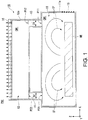
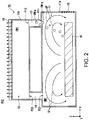
- FIG. 1 to FIG. 3 are schematic diagrams showing a cooling device 10 of the present embodiment.
- the cooling device 10 cools a heating element HE.
- the heating element HE is, for example, a coil of a motor.
- the cooling device 10 includes a cooling chamber 11, a radiator chamber 12, a first connection path 13, a second connection path 14, and an elastic part 15.
- a first cooling medium CM1 is filled into the cooling chamber 11, into the radiator chamber 12, into the first connection path 13, and into the second connection path 14.
- the first cooling medium CM1 is, for example, a fluorine-based inert liquid.
- the first cooling medium CM1 has, for example, an insulation property.
- the type of the first cooling medium CM1 can be selected according to a maximum heat generation temperature of the heating element HE.
- the first cooling medium CM1 when it is described that the first cooling medium CM1 is filled into a certain space, this is not limited to a case in which only the inside of the certain space is filled with only the first cooling medium CM1.
- the cooling chamber 11 is surrounded by a wall 11a.
- the cooling chamber 11 cools the heating element HE using the first cooling medium CM1.
- the heating element HE is housed in the cooling chamber 11.
- the radiator chamber 12 is surrounded by a wall 12a.
- the radiator chamber 12 releases heat of the first cooling medium CM1 to the outside.
- a heat absorbing part 16 is attached to the wall 12a of the radiator chamber 12. In the example in FIG. 1 , the heat absorbing part 16 is attached to, for example, the upper side of the radiator chamber 12 in the vertical direction.
- the heat absorbing part 16 is, for example, a part included in an instrument to which the cooling device 10 is attached.
- the heat absorbing part 16 absorbs heat from the first cooling medium CM1 in the radiator chamber 12.
- the heat absorbing part 16 can absorb heat from the first cooling medium CM1 in the radiator chamber 12.
- the heat absorbing part 16 may be, for example, a heat sink made of a member having a relatively high thermal conductivity.
- the heat absorbing part 16 may be a fan that blows air to the radiator chamber 12.
- the heat absorbing part 16 may be a member including a flow path through which a cooling medium flows.
- the radiator chamber 12 releases, for example, heat of the first cooling medium CM1 to the heat absorbing part 16. At least a part of the radiator chamber 12 is positioned above the cooling chamber 11 in the vertical direction. In the present embodiment, for example, the entire radiator chamber 12 is positioned above the cooling chamber 11 in the vertical direction.
- the first connection path 13 and the second connection path 14 connect the cooling chamber 11 to the radiator chamber 12.
- the first connection path 13 and the second connection path 14 extend in the vertical direction (the Z axis direction).
- the lower end of the first connection path 13 in the vertical direction and the lower end of the second connection path 14 in the vertical direction are connected to the upper end of the cooling chamber 11 in the vertical direction. That is, the first connection path 13 and the second connection path 14 are connected to the upper end of the cooling chamber 11 in the vertical direction.
- the upper end of the first connection path 13 in the vertical direction and the upper end of the second connection path 14 in the vertical direction are connected to the lower end of the radiator chamber 12 in the vertical direction.
- a part P12 in which the first connection path 13 is connected to the radiator chamber 12 is positioned above a part P11 in which the first connection path 13 is connected to the cooling chamber 11 in the vertical direction.
- the part P12 is positioned at, for example, one end (+X side) of the radiator chamber 12 in the horizontal direction.
- the part P11 is positioned, for example, near one end of the cooling chamber 11 in the horizontal direction.
- a part P22 in which the second connection path 14 is connected to the radiator chamber 12 is positioned above a part P21 in which the second connection path 14 is connected to the cooling chamber 11 in the vertical direction.
- the part P22 is positioned at, for example, the other end (-X side) of the radiator chamber 12 in the horizontal direction.
- the part P21 is positioned, for example, near the other end of the cooling chamber 11 in the horizontal direction.
- a shape of a cross section (XY cross section) orthogonal to a direction (the Z axis direction) in which the first connection path 13 extends is not particularly limited, and may be, for example, a circular shape.
- a shape of a cross section (XY cross section) orthogonal to a direction (the Z axis direction) in which the second connection path 14 extends is not particularly limited, and may be, for example, a circular shape.
- a size of the first connection path 13 in a direction (the X axis direction, the Y axis direction) orthogonal to the direction (the Z axis direction) in which the first connection path 13 extends and a size of the second connection path 14 in a direction (the X axis direction, the Y axis direction) orthogonal to a direction (the Z axis direction) in which the second connection path 14 extends have a size at which at least a part of the vaporized first cooling medium CM1 is retained in the first connection path 13 or the second connection path 14.
- the size of the first connection path 13 in a direction orthogonal to the direction in which the first connection path 13 extends is an inner diameter D1 of the first connection path 13.
- the size of the second connection path 14 in a direction orthogonal to the direction in which the second connection path 14 extends is an inner diameter D2 of the second connection path 14.
- the inner diameter D1 of the first connection path 13 and the inner diameter D2 of the second connection path 14 are preferably, for example, in a range of about 5 mm or more and 10 mm or less.
- the inner diameter D1 and the inner diameter D2 are set to have such sizes, bubbles CM1g which are the vaporized first cooling medium CM1 are likely to be retained in the first connection path 13 and in the second connection path 14.
- the elastic part 15 is in contact with the first cooling medium CM1.
- the elastic part 15 is made of an elastic material.
- a material of the elastic part 15 is not particularly limited as long as the material is elastic.
- a material of the elastic part 15 is, for example, rubber.
- the elastic part 15 is, for example, a part of the wall 11a constituting the cooling chamber 11.
- the cooling device 10 of the present embodiment includes three cooling phases, that is, a first cooling phase PH1, a second cooling phase PH2, and a third cooling phase PH3.
- the three cooling phases are appropriately switched between according to a temperature of the heating element HE, and it is possible to efficiently cool the heating element HE.
- the three cooling phases are switched between in the order of the first cooling phase PH1, the second cooling phase PH2, and the third cooling phase PH3 as the temperature of the heating element HE increases.
- FIG. 1 shows the cooling device 10 in the first cooling phase PH1.
- the first cooling phase PH1 is a phase in which the heating element HE is cooled by a convective flow CF of the first cooling medium CM1 generated in the cooling chamber 11.
- a temperature of the first cooling medium CM1 positioned around the heating element HE increases.
- the first cooling medium CM1 whose temperature has increased rises in the cooling chamber 11 and the convective flow CF is generated. That is, in the present embodiment, when the temperature of the first cooling medium CM1 has increased, the convective flow CF of the first cooling medium CM1 is generated in the cooling chamber 11.
- the first cooling medium CM1 When the convective flow CF is generated, the first cooling medium CM1 is stirred in the cooling chamber 11 by the convective flow CF. Accordingly, the first cooling medium CM1 positioned around the heating element HE can be circulated in the cooling chamber 11 and the heating element HE can be cooled. In the first cooling phase PH1, the temperature of the heating element HE is lower than a boiling point of the first cooling medium CM1.
- the cooling chamber 11 is connected to the radiator chamber 12 at only the first connection path 13 and the second connection path 14. Therefore, in a natural state, the first cooling medium CM1 is unlikely to be circulated between the first cooling medium CM1 in the cooling chamber 11 and the first cooling medium CM1 in the radiator chamber 12.
- the natural state includes a state in which no first cooling medium CM1 is vaporized and a state in which, even if the first cooling medium CM1 is vaporized, no bubbles CM1g to be described below are retained in the first connection path 13 or the second connection path 14.
- the natural state includes the first cooling phase PH1 and the second cooling phase PH2. That is, in the first cooling phase PH1 and the second cooling phase PH2, a circulation CY1 of the first cooling medium CM1 to be described below is unlikely to be generated between the cooling chamber 11 and the radiator chamber 12.
- the temperature of the first cooling medium CM1 remains relatively low.
- the cooling phase transitions from the first cooling phase PH1 to the second cooling phase PH2.
- FIG. 2 shows the cooling device 10 in the second cooling phase PH2.
- the second cooling phase PH2 is a phase in which the heating element HE is cooled by the convective flow CF of the first cooling medium CM1 and vaporization of the first cooling medium CM1.
- the first cooling medium CM1 around the heating element HE is vaporized and the bubbles CM1g are generated from a gas of the first cooling medium CM1. Therefore, due to latent heat generated when the first cooling medium CM1 is vaporized, heat of the heating element HE is absorbed and the heating element HE is cooled.
- the heating element HE in addition to the convective flow CF, the heating element HE is also cooled by vaporization of the first cooling medium CM1. Therefore, an effect of cooling the heating element HE in the second cooling phase PH2 is stronger than an effect of cooling the heating element HE in the first cooling phase PH2.
- the bubbles CM1g generated in the second cooling phase PH2 rise upward (+Z side) in the vertical direction and move, for example, in the first connection path 13.
- the temperature of the first cooling medium CM1 in the first connection path 13 remains relatively low. Accordingly, the bubbles CM1g that have moved in the first connection path 13 condense and return to a liquid again.
- the bubbles CM1g move only to the first connection path 13, but the present invention is not limited thereto.
- the bubbles CM1g may move to the second connection path 14 or may move to the radiator chamber 12 through the first connection path 13 or the second connection path 14.
- the bubbles CM1g that have moved into the second connection path 14 and the radiator chamber 12 condense and return to a liquid again. That is, when the first cooling medium CM1 in the cooling chamber 11 is vaporized, at least a part of the vaporized first cooling medium CM1 condenses in any of the first connection path 13, the second connection path 14, and the radiator chamber 12.
- the cooling phase returns from the second cooling phase PH2 to the first cooling phase PH1.
- the heating element HE when the heating element HE is not sufficiently cooled in the second cooling phase PH2, the temperature of the heating element HE rises, and an amount of the vaporized first cooling medium CM1 increases to a certain extent, the cooling phase transitions from the second cooling phase PH2 to the third cooling phase PH3.
- FIG. 3 shows the cooling device 10 in the third cooling phase PH3.
- the third cooling phase PH3 is a phase in which the heating element HE is cooled by vaporization of the first cooling medium CM1 and the circulation CY1 of the first cooling medium CM1 generated between the cooling chamber 11 and the radiator chamber 12.
- the inner diameter D1 of the first connection path 13 and the inner diameter D2 of the second connection path 14 are set such that the bubbles CM1g which are the vaporized first cooling medium CM1 are likely to be retained in the first connection path 13 and the second connection path 14. Therefore, when an amount of the bubbles CM1g increases, the bubbles CM1g are retained in the first connection path 13.
- a pressure difference is generated between the part P11 in which the first connection path 13 is connected to the cooling chamber 11 and the part P21 in which the second connection path 14 is connected to the cooling chamber 11 according to a length of a part in the vertical direction (the Z axis direction) in which the bubbles CM1g are retained in the first connection path 13. That is, a pressure in the part P11 is lower than a pressure in the part P21.
- the first cooling medium CM1 in the second connection path 14 moves to the cooling chamber 11 that is positioned on the lower side in the vertical direction due to gravity.
- the first cooling medium CM1 in the second connection path 14 moves into the cooling chamber 11
- a part of the first cooling medium CM1 in the cooling chamber 11 is pushed out to the first connection path 13 and moves to the radiator chamber 12 through the first connection path 13.
- a part of the first cooling medium CM1 in the radiator chamber 12 is pushed out to the second connection path 14 and moves to the cooling chamber 11 through the second connection path 14. Accordingly, the circulation CY1 of the first cooling medium CM1 is generated between the cooling chamber 11 and the radiator chamber 12.
- the circulation CY1 is generated so that the first cooling medium CM1 in the cooling chamber 11 flows to the radiator chamber 12 through the first connection path 13 and the first cooling medium CM1 in the radiator chamber 12 flows to the cooling chamber 11 through the second connection path 14.
- the first cooling medium CM1 in the radiator chamber 12 Since the temperature of the first cooling medium CM1 in the radiator chamber 12 remains relatively low in the first cooling phase PH1 and the second cooling phase PH2, the first cooling medium CM1 in the radiator chamber 12 is moved into the cooling chamber 11 by the circulation CY1, and thus the heating element HE can be further cooled.
- the heating element HE is cooled by the circulation CY1 of the first cooling medium CM1 in addition to vaporization of the first cooling medium CM1. Therefore, an effect of cooling the heating element HE in the third cooling phase PH3 is stronger than an effect of cooling the heating element HE in the second cooling phase PH2.
- a flow velocity of the circulation CY1 of the first cooling medium CM1 generated due to a pressure difference is higher than a flow velocity of the convective flow CF of the first cooling medium CM1. As a result, an effect of cooling the heating element HE is improved.
- the first cooling medium CM1 having a relatively high temperature in the cooling chamber 11 flows into the radiator chamber 12.
- the radiator chamber 12 releases heat of the first cooling medium CM1 to the outside the first cooling medium CM1 having a relatively high temperature flowing from the cooling chamber 11 is cooled in the radiator chamber 12 and becomes the first cooling medium CM1 having a relatively low temperature, and flows into the cooling chamber 11 again.
- the bubbles CM1g retained in the first connection path 13 are moved to the radiator chamber 12 together with the first cooling medium CM1 which is a liquid by the circulation CY1 of the first cooling medium CM1 and condense.
- the cooling phase is automatically changed among the first cooling phase PH1 to the third cooling phase PH3. Accordingly, it is possible to realize an appropriate cooling phase according to the temperature of the heating element HE and it is possible to efficiently cool the heating element HE.
- the type of the first cooling medium CM1 is preferably selected so that, for example, the cooling phase in the cooling device 10 can be changed among the first cooling phase PH1 to the third cooling phase PH3 described above.
- a substance that can be vaporized by heat of the heating element HE is preferably selected as the first cooling medium CM1. That is, the boiling point of the first cooling medium CM1 is preferably lower than a maximum temperature of the heating element HE. Accordingly, when the temperature of the heating element HE is higher than the boiling point of the first cooling medium CM1, the first cooling medium CM1 is vaporized, and the second cooling phase PH2 and the third cooling phase PH3 are realized. Therefore, the heating element HE is more easily cooled.
- the present embodiment it is possible to effectively cool the heating element HE by vaporization of the first cooling medium CM1 and the circulation CY1. Therefore, it is possible to improve cooling efficiency of the cooling device 10.
- a method in which an instrument for applying a driving force to the first cooling medium CM1 such as a pump is provided in the cooling device, and thus the circulation CY1 of the first cooling medium CM1 is generated between the cooling chamber 11 and the radiator chamber 12 may also be conceived.
- the size of the cooling device is increased by the pump or the like.
- the bubbles CM1g are used, gravity applied to the first cooling medium CM1 is used as a driving force, and thus the circulation CY1 of the first cooling medium CM1 can be generated.
- a flow velocity of the circulation CY1 is higher than a flow velocity of the convective flow CF. Therefore, according to the present embodiment, it is possible to improve cooling efficiency of the cooling device 10.
- the generated bubbles CM1g condense in any of the first connection path 13, the second connection path 14, and the radiator chamber 12 in which the temperature of the first cooling medium CM1 remains relatively low. Therefore, it is not necessary to provide a condenser irrespective of the size, and it is possible to prevent the size of the cooling device 10 from increasing.
- the cooling phase is likely to transition from the second cooling phase PH2 to the third cooling phase PH3. Accordingly, the cooling device 10 can more easily cool the heating element HE and it is possible to further improve cooling efficiency of the cooling device 10.
- the inner diameter D1 of the first connection path 13 is small enough for the bubbles CM1g to be retained, in the natural state, it is difficult for the first cooling medium CM1 of the radiator chamber 12 to move due to the first connection path 13 or the second connection path 14, and the circulation CY1 of the first cooling medium CM1 is unlikely to be generated between the cooling chamber 11 and the radiator chamber 12. Therefore, in the natural state, it is possible to prevent the occurrence of heat exchange between the cooling chamber 11 and the radiator chamber 12. As a result, the temperature of the first cooling medium CM1 in the radiator chamber 12 is likely to remain relatively low.
- the entire radiator chamber 12 is positioned above the cooling chamber 11 in the vertical direction. Therefore, in the third cooling phase PH3, the gravitational force on the first cooling medium CM1 due to a pressure difference is used, and the circulation CY1 of the first cooling medium CM1 is likely to be generated between the cooling chamber 11 and the radiator chamber 12.
- the first connection path 13 is connected to the upper end of the cooling chamber 11 in the vertical direction. Therefore, in the second cooling phase PH2 and the third cooling phase PH3, the bubbles CM1g are likely to move to the first connection path 13. Accordingly, the bubbles CM1g are likely to condense in the first connection path 13 or the radiator chamber 12. In addition, in the third cooling phase PH3, the bubbles CM1g are retained in the first connection path 13, and the circulation CY1 of the first cooling medium CM1 can be easily generated.
- the heating element HE is housed in the cooling chamber 11. Therefore, the first cooling medium CM1 comes directly in contact with the heating element HE. Therefore, it is possible to more easily cool the heating element HE by the first cooling medium CM1 and it is possible to further improve cooling efficiency of the cooling device 10.
- the cooling device 10 further includes the elastic part 15. Therefore, when the first cooling medium CM1 is vaporized and the bubbles CM1g are generated, the elastic part 15 is deformed, and it is possible to prevent a pressure in the cooling chamber 11, the radiator chamber 12, the first connection path 13, and the second connection path 14 from increasing. Accordingly, it is possible to prevent the boiling point of the first cooling medium CM1 from increasing and the heating element HE is appropriately and easily cooled.
- a higher boiling point of the first cooling medium CM1 is preferable. This is because the temperature in the cooling chamber 11 when the cooling phase transitions to the second cooling phase PH2 and the third cooling phase PH3 increases, a temperature difference from the outside increases, and cooling efficiency is improved.
- the cooling device includes the elastic part 15 that absorbs a pressure variation, and a pressure absorption width of the elastic part 15 is adjusted. Therefore, a pressure in the second cooling phase PH2 and the third cooling phase PH3 can increase in a range in which the cooling phase can transition to the second cooling phase PH2 and the third cooling phase PH3. Therefore, it is possible to further improve cooling efficiency in the second cooling phase PH2 and the third cooling phase PH3.
- the elastic part 15 is a part of the wall 11 a constituting the cooling chamber 11. Therefore, it is possible to prevent a pressure in the cooling chamber 11 in which the bubbles CM1g are generated from increasing, and it is possible to prevent the boiling point of the first cooling medium CM1 in the cooling chamber 11 from increasing.
- the first cooling phase PH1 in which the convective flow CF of the first cooling medium CM1 is generated is provided. Therefore, even if the temperature of the heating element HE is relatively low and the first cooling medium CM1 is not vaporized, it is possible to cool the heating element HE by the convective flow CF of the first cooling medium CM1.
- the cooling phase when the cooling device 10 cools the heating element HE, for example, the cooling phase may be changed only between the first cooling phase PH1 and the second cooling phase PH2.
- the first cooling medium CM1 in the cooling chamber 11 is vaporized and thus the temperature of the heating element HE is lower than the boiling point of the first cooling medium CM1. Accordingly, the cooling phase is alternately switched between the first cooling phase PH1 and the second cooling phase PH2, and the heating element HE is appropriately and easily cooled according to the temperature.
- the part P12 in which the first connection path 13 is connected to the radiator chamber 12 may be positioned at the same position as the part P11 in which the first connection path 13 is connected to the cooling chamber 11. In this case, a pressure difference when the cooling phase transitions from the second cooling phase PH2 to the third cooling phase PH3 is generated according to the inner diameter D1 of the first connection path 13.
- the heating element HE may be cooled.
- the heating element HE is attached to the wall 11a of the cooling chamber 11, and the heating element HE is cooled by the first cooling medium CM1 through the wall 11a.
- the elastic part 15 may be a part of the wall 12a of the radiator chamber 12, or a part of a wall that constitutes the first connection path 13 and the second connection path 14.
- the elastic part 15 may be a sphere made of an elastic material or the like. In this case, the elastic part 15 is positioned in the cooling chamber 11, the radiator chamber 12, the first connection path 13, or the second connection path 14. In addition, in the present embodiment, the elastic part 15 may be a gas such as air.
- the present invention is not limited thereto.
- the bubbles CM1g can move to both the first connection path 13 and the second connection path 14, and when the cooling phase transitions from the second cooling phase PH2 to the third cooling phase PH3, the bubbles CM1g may be retained both in the first connection path 13 and the second connection path 14.
- a pressure of a part in which the connection path on the side in which more bubbles CM1g are retained is connected to the cooling chamber 11 decreases, and the cooling phase transitions to the third cooling phase PH3 due to a pressure difference therebetween.
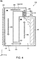
- FIG. 4 is a schematic diagram showing a cooling device 110 which is another example of the present embodiment.
- FIG. 4 shows the cooling device 110 in the third cooling phase PH3.
- the cooling device 110 includes a cooling chamber 111, a radiator chamber 112, a first connection path 113, a second connection path 114, and an elastic part 115.
- the cooling chamber 111 and the radiator chamber 112 are arranged in the horizontal direction (the X axis direction).
- the cooling chamber 111 and the radiator chamber 112 extend in the vertical direction (the Z axis direction).
- a position of the lower end of the cooling chamber 111 in the vertical direction is the same as a position of the lower end of the radiator chamber 112 in the vertical direction.
- a position of the upper end of the radiator chamber 112 in the vertical direction is above, in the vertical direction, a position of the upper end of the cooling chamber 111 in the vertical direction. That is, in such a configuration, a part of the radiator chamber 112 is positioned above the cooling chamber 111 in the vertical direction.
- a heat absorbing part 116 is attached to the radiator chamber 112.
- the heat absorbing part 116 is the same as the heat absorbing part 116 shown in FIG. 1 to FIG. 3 except that it is positioned on the side (-X side) opposite to the cooling chamber 111 in the horizontal direction (the X axis direction) of the radiator chamber 112.
- the first connection path 113 includes a first linear part 113a and a second linear part 113b.
- the first linear part 113a linearly extends from the upper end of the cooling chamber 111 in the vertical direction to the upper side thereof in the vertical direction.
- the second linear part 113b linearly extends from the upper end of the first linear part 113a in the vertical direction toward the side (-X side) of the radiator chamber 112 in the horizontal direction (the X axis direction).
- the end on the side of the radiator chamber 112 of the second linear part 113b is connected to the upper end in the vertical direction at the end on the side (+X side) of the cooling chamber 111 of the radiator chamber 112.
- the entire first connection path 13 is positioned above the cooling chamber 111 in the vertical direction.
- the second connection path 114 extends in the horizontal direction (the X axis direction).
- the second connection path 114 is connected to the lower end of the cooling chamber 111 in the vertical direction and the lower end of the radiator chamber 112 in the vertical direction.
- a position of the lower end of the second connection path 114 in the vertical direction is the same as, for example, a position of the lower end of the cooling chamber 111 in the vertical direction and a position of the lower end of the radiator chamber 112 in the vertical direction.
- the second connection path 114 does not include a part that is positioned above the cooling chamber 111 in the vertical direction. In other words, in such a configuration, the entire second connection path 114 is positioned vertically below the upper end of the cooling chamber 111 in the vertical direction.
- the elastic part 115 is a part of the wall of the radiator chamber 112.
- the elastic part 115 is provided on a wall that is positioned at the lower end of the radiator chamber 112 in the vertical direction.
- the configuration of the cooling device 110 is otherwise the same as the configuration of the cooling device 10 shown in FIG. 1 to FIG. 3 .
- the pressure difference is determined according to a length of the bubbles CM1g in the vertical direction (the Z axis direction) that are retained in the first linear part 113a of the first connection path 113.
- the bubbles CM1g move only to the first connection path 113.
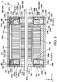
- FIG. 5 is a cross-sectional view showing a motor 1 of the present embodiment.
- FIG. 6 and FIG. 8 are perspective views showing a part of the motor 1 of the present embodiment.
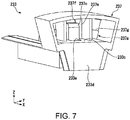
- FIG. 7 is a perspective view showing an upper insulator 233 of the present embodiment.
- a first connection path member 235 is indicated by a two-dot line.
- a direction in which the central axis J extends (the X axis direction) is defined as a longitudinal direction.
- a positive side in the X axis direction (+X side) with respect to a certain object may be referred to as a "front side” and a negative side in the X axis direction (-X side) with respect to a certain object may be referred to as a "rear side.”
- the longitudinal direction, the front side, and the rear side are names that are simply used for explanation and do not limit the actual positional relationship and direction.
- a direction (the X axis direction) parallel to the central axis J may be simply referred to as an "axis direction”
- a radial direction with respect to the central axis J may be simply referred to as a “radial direction”
- a circumferential direction with respect to the central axis J, that is, an axial circumference of the central axis J may be simply referred to as a "circumferential direction.”
- the motor 1 of the present embodiment includes a cooling device 210, a rotor 220, a stator 230, a housing 240, a first lid member 250, a second lid member 251, a first connection pipe 260, a second connection pipe 261, and a cooling jacket (heat absorbing part) 216.
- the cooling device 210 includes a plurality of cooling chambers 211, a radiator chamber 212, a first connection path 213, a second connection path 214, and an elastic part 215.
- a cooling chamber 211 includes a first cooling chamber (cooling chamber) 211a and a second cooling chamber (cooling chamber) 211b.
- the first cooling medium CM1 is filled into the cooling chamber 211, the radiator chamber 212, the first connection path 213, and the second connection path 214.
- the first cooling medium CM1 has, for example, an insulation property.
- the cooling chamber 211, the first connection path 213, the second connection path 214, and the elastic part 215 are provided in the stator 230.
- the radiator chamber 212 is provided in the housing 240. Components of the cooling device 210 will be described below together with the configuration of the stator 230 and the housing 240.
- the rotor 220 includes a shaft 221, a rotor core 222, and a rotor magnet 223.
- the shaft 221 is centered on the central axis J that extends in one direction (the X axis direction).
- the shaft 221 is rotatably supported around the central axis J by a bearing (not shown).
- the rotor core 222 surrounds the shaft 221 with respect to an axis and is fixed to the shaft 221.
- the rotor magnet 223 is fixed to the outer surface along the central axis J in the rotor core 222.
- the rotor core 222 and the rotor magnet 223 rotate integrally with the shaft 221.
- the stator 230 is positioned outward from the rotor 220 in the radial direction.
- the stator 230 surrounds the rotor 220 with respect to the central axis J.
- the stator 230 includes a stator core 231, a plurality of coils 232, the upper insulator (insulator) 233, and a lower insulator (insulator) 234.
- the stator core 231 includes a core back part 231a and a tooth part 231b.
- the shape of the core back part 231a is, for example, a cylindrical shape concentric with the shaft 221.
- the tooth part 231b extends from an inner surface of the core back part 231 a to the shaft 221.
- a plurality of tooth parts 231b are provided and arranged at equal intervals in the circumferential direction of the inner surface of the core back part 231a.
- the coil 232 is formed by winding a conductive wire.
- the coil 232 is wound on each of the tooth parts 231b through the upper insulator 233 or the lower insulator 234.
- the upper insulator 233 and the lower insulator 234 are mounted on each of the tooth parts 231b.
- the coil 232 excites the stator core 231.
- the upper insulator 233 is mounted on the tooth part 231b that is positioned above the shaft 221 in the vertical direction among the plurality of tooth parts 231b.
- the upper insulator 233 includes an insulator main body 237, the first connection path member 235, and a second connection path member 236.
- the first connection path member 235 and the second connection path member 236 are attached to the insulator main body 237.
- the first connection path member 235 is attached to the +X side end of the insulator main body 237 in the horizontal direction.
- the second connection path member 236 is attached to the -X side end of the insulator main body 237 in the horizontal direction.
- the first connection path member 235 and the second connection path member 236 are, for example, members that are separate from the insulator main body 237.
- the insulator main body 237 includes the first cooling chamber 211a, a housing recess 237a that is positioned on the +X side of the insulator main body 237 in the horizontal direction, a housing recess 237b that is positioned on the -X side of the insulator main body 237 in the horizontal direction, a rib part 237c that is positioned on the +X side of the insulator main body 237 in the horizontal direction, and a rib part 237d that is positioned on the -X side of the insulator main body 237 in the horizontal direction. That is, the upper insulator 233 includes the first cooling chamber 211a, the housing recess 237a, the housing recess 237b, the rib part 237c, and the rib part 237d.
- the housing recess 237a and the rib part 237c, and the housing recess 237b and the rib part 237d are the same except that they are reversed in the axis direction (the X axis direction).
- the first cooling chamber 211a has the same function as the cooling chamber 11 described above with reference to FIG. 1 to FIG. 3 .
- the first cooling chamber 211 a has an annular shape that surrounds both sides of the tooth part 231b in the axis direction and both sides of the tooth part 231b in the circumferential direction.
- the coil 232 positioned above the central axis J in the vertical direction is housed in the first cooling chamber 211 a. That is, in the present embodiment, the heating element HE cooled by the first cooling chamber 211a is the coil 232.
- the first cooling chamber 211a includes a mounting wall 233a, an inner wall 233b, an outer wall 233c, and a lid 233d.
- the mounting wall 233a, the inner wall 233b, the outer wall 233c, and the lid 233d are provided on both end sides of the stator core 231 in the axis direction (the X axis direction).
- a side on the stator core 231 in the axis direction may be simply referred to as “an inner side in the axis direction” and a side opposite to the stator core 231 in the axis direction may be simply referred to as “an outer side in the axis direction.”
- the mounting wall 233a is a part that is in contact with and mounted on the tooth part 231b.
- the mounting wall 233a is positioned between the stator core 231 and the coil 232 in the axis direction (the X axis direction). That is, at least a part of the upper insulator 233 is positioned between the stator core 231 and the coil 232.
- the inner wall 233b extends from an inner side end (the lower side in the vertical direction) of the mounting wall 233a in the radial direction to the outer side in the axis direction.
- the inner wall 233b is a member that is separate from the mounting wall 233a, the outer wall 233c, and the lid 233d.
- the elastic part 215 is provided on the inner wall 233b.
- the elastic part 215 has the same function as the elastic part 15 described above with reference to FIG. 1 to FIG. 3 . That is, when the elastic part 15 is deformed, it is possible to prevent a pressure from increasing in the plurality of cooling chambers 211, the radiator chamber 212, the first connection path 213, and the second connection path 214.
- the elastic part 215 is positioned in a mounting hole 233f that penetrates the inner wall 233b in the radial direction.
- the elastic part 215 blocks the mounting hole 233f.
- the elastic part 215 is positioned at the outer side end of the inner wall 233b in the axis direction.
- the elastic part 215 has, for example, a shape that protrudes inward in the radial direction.
- the outer wall 233c extends from the outer side end of the mounting wall 233a in the radial direction to the outer side in the axis direction.
- the outer wall 233c includes a connection hole 233e that is a hole that penetrates the outer wall 233c in the radial direction (vertical direction).
- the lid 233d connects the outer side end of the inner wall 233b in the axis direction to the outer side end of the outer wall 233c in the axis direction.
- the lid 233d covers the outer side of the coil 232 in the axis direction.
- the housing recess 237a is recessed from the outer side of the insulator main body 237 in the axis direction (+X side) to the inner side in the axis direction (-X side).
- the housing recess 237a is positioned on the outer side of the first cooling chamber 211 a in the radial direction (the upper side in the vertical direction, +Z side).
- An inner side wall of the housing recess 237a in the radial direction (the lower side in the vertical direction, -Z side) is, for example, the outer wall 233c of the first cooling chamber 211a.
- the housing recess 237a includes a bottom 237e.
- the bottom 237e is an inner side wall of the housing recess 237a in the axis direction.
- the bottom 237e includes a first connection hole 237f that is a hole that penetrates the bottom 237e in the axis direction.
- the first connection hole 237f is positioned at the outer side of the rib part 237c in the radial direction (the upper side in the vertical direction, +Z side).
- the first connection hole 237f is connected to the radiator chamber 212.
- the bottom 237e includes a second connection hole 237g that is a hole that penetrates the bottom 237e in the axis direction.
- the second connection hole 237g is connected to the radiator chamber 212.
- a second connection path 218 to be described below is connected to the second connection hole 237g.
- the rib part 237c projects from the bottom 237e to the outer side in the axis direction (+X side).
- the rib part 237c is connected to the outer wall 233c.
- the outer side end of a connection part of the bottom 237e in the rib part 237c in the radial direction (the upper side in the vertical direction, +Z side) is positioned at the inner side end (the lower side in the vertical direction, -Z side) in the radial direction on the inner edge of the first connection hole 237f.
- the outer side end of a connection part of the outer wall 233c in the rib part 237c in the axis direction is positioned at the inner side end in the axis direction (-X side) on the inner edge of the connection hole 233e.
- the first connection path member 235 is housed in the housing recess 237a.
- the first connection path member 235 is fixed into the housing recess 237a.
- the first connection path member 235 faces the rib part 237c.
- the first connection path 213 is provided between the first connection path member 235 and the rib part 237c. That is, the first connection path member 235 and the rib part 237c constitute the first connection path 213.
- the first connection path 213 has the same function as the first connection path 13 described above with reference to FIG. 1 to FIG. 3 .
- the first connection path 213 is constituted by a surface that faces the rib part 237c in the first connection path member 235 and a surface that faces the first connection path member 235 in the rib part 237c. That is, the first connection path member 235 includes at least a part of the first connection path 213.
- the first connection path 213 is connected to the first cooling chamber 211 a through the connection hole 233e of the outer wall 233c.
- the first connection path 213 is connected to the radiator chamber 212 through the first connection hole 237f.
- the entire first connection path 213 is positioned above the first cooling chamber 211 a in the vertical direction.
- the first connection path 213 includes a first linear part 213a, an arc part 213b, and a second linear part 213c.
- the first linear part 213a extends outward from the first cooling chamber 211a in the radial direction (the upper side in the vertical direction).
- the arc part 213b is connected to the outer side end of the first linear part 213a in the radial direction (the upper side in the vertical direction, +Z side).
- the arc part 213b has an arc shape that is positioned on the inner side in the axis direction (-X side) toward the outer side in the radial direction (the upper side in the vertical direction).
- the second linear part 213c is connected to the inner side end of the arc part 213b in the axis direction.
- the second linear part 213c extends to the radiator chamber 212 in the axis direction (the X axis direction).
- the second connection path member 236 is housed in the housing recess 237b.
- the second connection path member 236 is fixed into the housing recess 237b.
- the second connection path 214 is provided between the second connection path member 236 and the rib part 237d.
- the second connection path 214 has the same function as the second connection path 14 described above with reference to FIG. 1 to FIG. 3 .
- the second connection path 214 is constituted by a surface that faces the rib part 237d in the second connection path member 236 and a surface that faces the second connection path member 236 in the rib part 237d. That is, the second connection path member 236 includes at least a part of the second connection path 214. The other parts of the second connection path 214 are the same as those of the first connection path 213 except that they are reversed in the axis direction.
- the lower insulator 234 is mounted, for example, on the tooth part 231b that is positioned below the shaft 221 in the vertical direction among the tooth parts 231b.
- the lower insulator 234 includes the second cooling chamber 211b.
- the second cooling chamber 211b is positioned below the first cooling chamber 211a in the vertical direction.
- the second cooling chamber 211b has an annular shape that surrounds both sides of the tooth part 231b in the axis direction and both sides thereof in the circumferential direction.
- the coil 232 positioned below the central axis J in the vertical direction is housed in the second cooling chamber 211b. That is, in the present embodiment, the heating element HE cooled by the second cooling chamber 211b is the coil 232.
- the second cooling chamber 211b includes a mounting wall 234a, an inner wall 234b, an outer wall 234c, and a lid 234d.
- the mounting wall 234a, the inner wall 234b, the outer wall 234c, and the lid 234d are provided on both end sides of the stator core 231 in the axis direction (the X axis direction).
- the mounting wall 234a is the same as the mounting wall 233a of the first cooling chamber 211a.
- the inner wall 234b is the same as the inner wall 233b of the first cooling chamber 211a.
- the outer wall 234c does not include the connection hole 233e.
- the other parts of the outer wall 234c are the same as those of the outer wall 233c of the first cooling chamber 211 a.
- the lid 234d includes a connection hole 234e that penetrates the lid 234d in the axis direction (the X axis direction).
- the first connection pipe 260 is connected to the connection hole 234e that is positioned on the front side (+X side) of the stator core 231.
- the second connection pipe 261 is connected to the connection hole 234e that is positioned on the rear side (-X side) of the stator core 231.
- the other parts of the lid 234d are the same as those of the lid 233d of the first cooling chamber 211a.
- the housing 240 has a tubular shape that surrounds the stator core 231 in the circumferential direction.
- the housing 240 has, for example, a cylindrical shape centered on the central axis J.
- the stator core 231 is fitted into the inner circumferential surface of the housing 240.
- the housing 240 is made of, for example, a metal.
- the housing 240 includes the radiator chamber 212.
- the radiator chamber 212 has the same function as the radiator chamber 12 described above with reference to FIG. 1 to FIG. 3 .
- the entire radiator chamber 212 is positioned above the first cooling chamber 211 a in the vertical direction.
- the radiator chamber 212 extends to, for example, the entire housing 240 in the axis direction (the X axis direction).
- the radiator chamber 212 is provided for each upper insulator 233.
- the first lid member 250 is attached to the front side (+X side) of the stator 230.
- the first lid member 250 covers the front side of the stator 230.
- the first lid member 250 includes an annular bottom 250a, an inner tubular part 250b, an outer tubular part 250c, and an annular lid 250d.
- the annular bottom 250a has, for example, an annular plate shape centered on the central axis J.
- the annular bottom 250a is in contact with the lid 233d on the front side (+X side) in the upper insulator 233 and the lid 234d on the front side in the lower insulator 234.
- the annular bottom 250a includes an insertion hole 250e that penetrates the annular bottom 250a in the axis direction (the X axis direction).
- the insertion hole 250e faces the connection hole 234e in the axis direction (the X axis direction).
- the inner tubular part 250b has, for example, a cylindrical shape that extends from the inner edge inside the annular bottom 250a in the radial direction to the front side (+X side).
- the outer tubular part 250c has, for example, a cylindrical shape that extends from the outer edge outward from the annular bottom 250a in the radial direction to the front side.
- the annular lid 250d is connected to the front side end of the inner tubular part 250b and the front side end of the outer tubular part 250c.
- the annular lid 250d covers the front side of the annular bottom 250a.
- the first connection pipe 260 is housed inside the first lid member 250, that is, a first connection space 252 which is a space surrounded by the annular bottom 250a, the inner tubular part 250b, the outer tubular part 250c, and the annular lid 250d.
- the second lid member 251 is attached to the rear side (-X side) of the stator 230.
- the second lid member 251 covers the rear side of the stator 230.
- the second lid member 251 is the same as the first lid member 250 except that it is reversed in the axis direction (the X axis direction).
- the second connection pipe 261 is housed in a second connection space 253 that is a space inside the second lid member 251.
- the first connection pipe 260 includes a cooling chamber connection part 260a, an arcuate part 260b, and a radiator chamber connection part 260c.
- the cooling chamber connection part 260a extends in the axis direction (the X axis direction).
- the end on the rear side (-X side) of the cooling chamber connection part 260a is inserted into the insertion hole 250e.
- the inside of the cooling chamber connection part 260a is connected to the second cooling chamber 211b.
- the arcuate part 260b is connected to the end on the front side (+X side) of the cooling chamber connection part 260a.
- the arcuate part 260b extends in the first connection space 252 in the circumferential direction from the lower side in the vertical direction to the upper side in the vertical direction.
- the radiator chamber connection part 260c is connected to the upper end of the arcuate part 260b in the vertical direction.
- the radiator chamber connection part 260c extends in the axis direction (the X axis direction).
- the end on the rear side (-X side) of the radiator chamber connection part 260c is connected to the radiator chamber 212.
- the second connection pipe 261 is the same as the first connection pipe 260 except that it is reversed in the axis direction (the X axis direction).
- the inside of the first connection pipe 260 is a first connection path 217 into which the first cooling medium CM1 is filled.
- the first connection path 217 is connected to the second cooling chamber 211b and the radiator chamber 212.
- the inside of the second connection pipe 261 is the second connection path 218 into which the first cooling medium CM1 is filled.
- the second connection path 218 is connected to the second cooling chamber 211b and the radiator chamber 212. That is, the first connection path 217 and the second connection path 218 connected to the second cooling chamber 211b are connected to the radiator chamber 212 to which the first cooling chamber 211a is connected.
- the second connection path 218 is connected to the radiator chamber 212 through the second connection hole 237g (refer to FIG. 7 ).
- the first connection path 217 has the same function as the first connection path 13 described above with reference to FIG. 1 to FIG. 3 .
- the second connection path 218 has the same function as the second connection path 14 described above with reference to FIG. 1 to FIG. 3 . That is, in the present embodiment, the cooling device 210 includes the first connection path 217 and the second connection path 218.
- the cooling jacket 216 has a cylindrical shape that surrounds the outer sides of the stator 230, the first lid member 250, and the second lid member 251 in the radial direction.
- the cooling jacket 216 includes a cooling flow path 216a.
- a second cooling medium CM2 is housed in the cooling flow path 216a. That is, the second cooling medium CM2 is housed in the cooling jacket 216.
- the second cooling medium CM2 absorbs heat from the first cooling medium CM1 in the radiator chamber 212. That is, the cooling jacket 216 absorbs heat from the first cooling medium CM1 in the radiator chamber 212 by the second cooling medium CM2 in the cooling flow path 216a.
- the second cooling medium CM2 a medium that can absorb heat in the radiator chamber 212 may be used.
- the second cooling medium CM2 may be the same as or different from the first cooling medium CM1.
- the second cooling medium CM2 is, for example, water.
- the cooling flow path 216a is positioned above the radiator chamber 212 in the vertical direction.
- An input port 216b is connected to the end on the front side (+X side) of the cooling flow path 216a.
- An output port 216c is connected to the end on the rear side (-X side) of the cooling flow path 216a.
- the second cooling medium CM2 flows into the cooling flow path 216a from the input port 216b.
- the second cooling medium CM2 flowing into the cooling flow path 216a flows out from the output port 216c. Accordingly, the second cooling medium CM2 circulates in the cooling flow path 216a.
- the motor 1 since the motor 1 includes the cooling device 210 having the same cooling structure as the cooling device 10 shown in FIG. 1 to FIG. 3 , it is possible to efficiently cool the motor 1 while preventing the size of the motor 1 from increasing.
- the heating element HE is the coil 232, it is possible to efficiently cool the coil 232.
- the first cooling medium CM1 has an insulation property, and the coil 232 is housed in the cooling chamber 211. Therefore, while the coil 232 is immersed in the first cooling medium CM1, it is possible to cool the coil 232. Accordingly, it is possible to additionally cool the coil 232.
- the cooling device 210 of the present embodiment does not have particularly a strong effect when it is used for the motor 1.
- the radiator chamber 212 when the radiator chamber 212 is arranged outward from the stator core 231 in the radial direction for each coil 232, the radiator chamber 212 of the coil 232 positioned below the central axis J in the vertical direction is positioned below the cooling chamber 211 in which the coil 232 is housed in the vertical direction. Therefore, it is not possible to use gravity on the first cooling medium CM1 as a driving force generating the circulation CY1, and the third cooling phase PH3 is not realized. Therefore, it is not possible to efficiently cool the coil 232 positioned below the central axis J in the vertical direction in some cases.
- the first connection path 217 and the second connection path 218 that connect the second cooling chamber 211b positioned below the first cooling chamber 211 a in the vertical direction and the radiator chamber 212 to which the first cooling chamber 211a is connected are provided. Therefore, the radiator chamber 212 positioned above the second cooling chamber 211b in the vertical direction can be connected to the second cooling chamber 211b which cools the coil 232 positioned below the central axis J in the vertical direction. Therefore, according to the present embodiment, it is possible to efficiently cool the coil 232 positioned below the central axis J in the vertical direction using the third cooling phase PH3.
- the upper insulator 233 and the lower insulator 234 include the cooling chamber 211. Therefore, the coil 232 is easily housed in the cooling chamber 211.
- the first connection path member 235 including at least a part of the first connection path 213 and the second connection path member 236 including at least a part of the second connection path 214 are members that are separate from the insulator main body 237. Therefore, it is possible to change the size of the first connection path 213 and the size of the second connection path 214 by exchanging only the first connection path member 235 and the second connection path member 236. Therefore, according to the present embodiment, it is easy to change the size of the first connection path 213 and the size of the second connection path 214.
- the cooling jacket 216 is provided as a heat absorbing part, the temperature of the first cooling medium CM1 in the radiator chamber 212 can remain relatively low. Accordingly, the coil 232 which is the heating element HE is more easily cooled.
- the elastic part 215 is provided in the radiator chamber 212 in the motor 1 of the present embodiment, since it is necessary to secure a space in which the elastic part 215 is deformed, there is a risk of the size of the motor 1 increasing, for example, in the radial direction.
- the elastic part 215 is provided in the cooling chamber 211, a space inside the upper insulator 233 and the lower insulator 234 in the radial direction can be used as a space in which the elastic part 215 is deformed. Accordingly, it is possible to provide the elastic part 215 while preventing the size of the motor 1 from increasing in the radial direction.
- the first connection path 213 and the second connection path 214, and the first connection path 217 and the second connection path 218 may be connected to the cooling chamber 211.
- the radiator chamber 212 is provided outward from the tooth part 231b on which each coil 232 is mounted in the radial direction. In such a configuration, it is possible to efficiently cool all of the coils 232 even if a motor 1 reversed in the vertical direction and is used.
- only one cooling chamber 211 may be provided.
- all of the coils 232 may be housed in one cooling chamber 211.
- an instrument to which the cooling device of the present embodiment is applied is not particularly limited, and the cooling device may be mounted in an instrument other than a motor.
Landscapes
- Engineering & Computer Science (AREA)
- Physics & Mathematics (AREA)
- Thermal Sciences (AREA)
- Mechanical Engineering (AREA)
- General Engineering & Computer Science (AREA)
- Life Sciences & Earth Sciences (AREA)
- Sustainable Development (AREA)
- Power Engineering (AREA)
- Cooling Or The Like Of Electrical Apparatus (AREA)
- Motor Or Generator Cooling System (AREA)
- Cooling Or The Like Of Semiconductors Or Solid State Devices (AREA)
Description
- The present invention relates to a cooling device and a motor.
- For example, in
Patent Literature 1, a cooling device configured to cool a motor is described. In the cooling device inPatent Literature 1, a liquid refrigerant absorbs heat of a casing and evaporates, and a motor is cooled through the casing. - [Patent Literature 1]
Japanese Unexamined Patent Application Publication No.H9-23614 - In the cooling device described above, in order to return the liquid refrigerant that has evaporated and become a gas to a liquid again, a condenser is necessary. When a temperature of a heat generating object to be cooled becomes higher, since an amount of the liquid refrigerant evaporated increases, a larger-sized condenser is necessary. Accordingly, there is a problem of the size of the entire cooling device increasing.
- In view of the above problem, an object of an aspect of the present invention is to provide a cooling device having a structure through which it is possible to improve cooling efficiency while preventing the size increasing and a motor including such a cooling device.
- According to an aspect of the present invention, there is provided a cooling device configured to cool a heating element. The cooling device includes: a cooling chamber that cools the heating element by a first cooling medium; a radiator chamber that releases heat of the first cooling medium to an outside; and a first connection path and a second connection path that connect the cooling chamber to the radiator chamber, wherein at least a part of the radiator chamber is positioned above the cooling chamber in a vertical direction, wherein a part in which the first connection path is connected to the radiator chamber is positioned at a same part in which the first connection path is connected to the cooling chamber in the vertical direction or is positioned above a part in which the first connection path is connected to the cooling chamber, and when a part of the first cooling medium in the cooling chamber is vaporized, at least a part of the first cooling medium which is vaporized moves into the first connection path, and a circulation is generated in which the first cooling medium in the cooling chamber flows to the radiator chamber through the first connection path, and the first cooling medium in the radiator chamber flows into the cooling chamber through the second connection path.
- According to an aspect of the present invention, there is provided a cooling device configured to cool a heating element. The cooling device includes: a cooling chamber that cools the heating element by a first cooling medium; a radiator chamber that releases heat of the first cooling medium to an outside; and a first connection path and a second connection path that connect the cooling chamber to the radiator chamber, wherein at least a part of the radiator chamber is positioned above the cooling chamber in the vertical direction, wherein a part in which the first connection path is connected to the radiator chamber is positioned at a same part in which the first connection path is connected to the cooling chamber in the vertical direction or is positioned above a part in which the first connection path is connected to the cooling chamber, and when a part of the first cooling medium in the cooling chamber is vaporized, at least a part of the first cooling medium which is vaporized condenses in any one of the first connection path, the second connection path, and the radiator chamber.
- A motor according to an aspect of the present invention includes the above cooling device.
- According to an aspect of the present invention, there are provided a cooling device having a structure through which it is possible to improve cooling efficiency while preventing the size increasing and a motor including such a cooling device.
-
-
FIG. 1 is a schematic diagram showing a cooling device of the present embodiment. -
FIG. 2 is a schematic diagram showing the cooling device of the present embodiment. -
FIG. 3 is a schematic diagram showing the cooling device of the present embodiment. -
FIG. 4 is a schematic diagram showing a cooling device which is another example of the present embodiment. -
FIG. 5 is a cross-sectional view showing a motor of the present embodiment. -
FIG. 6 is a perspective view showing a part of the motor of the present embodiment. -
FIG. 7 is a perspective view showing an upper insulator of the present embodiment. -
FIG. 8 is a perspective view showing a part of the motor of the present embodiment. - A cooling device and a motor according to embodiments of the present invention will be described below with reference to the drawings. Here, the scope of the present invention is not limited to the following embodiments, and can be arbitrarily changed within the technical scope of the present invention. In addition, in the following drawings, in order to facilitate understanding of components, sizes, numbers, and the like in structures may be different from sizes, numbers, and the like in actual structures.
- In addition, in the drawings, an XYZ coordinate system is appropriately shown as a three-dimensional orthogonal coordinate system. In the XYZ coordinate system, a Z axis direction is a vertical direction. An X axis direction is a direction orthogonal to the Z axis direction and is a direction in which a central axis J in
FIG. 5 extends. The X axis direction is a left and right direction inFig. 1 . A Y axis direction is a direction that is orthogonal to both the X axis direction and the Z axis direction. -
FIG. 1 to FIG. 3 are schematic diagrams showing acooling device 10 of the present embodiment. As shown inFIG. 1 , thecooling device 10 cools a heating element HE. The heating element HE is, for example, a coil of a motor. Thecooling device 10 includes acooling chamber 11, aradiator chamber 12, afirst connection path 13, asecond connection path 14, and anelastic part 15. - A first cooling medium CM1 is filled into the
cooling chamber 11, into theradiator chamber 12, into thefirst connection path 13, and into thesecond connection path 14. The first cooling medium CM1 is, for example, a fluorine-based inert liquid. The first cooling medium CM1 has, for example, an insulation property. The type of the first cooling medium CM1 can be selected according to a maximum heat generation temperature of the heating element HE. - Here, in this specification, when it is described that the first cooling medium CM1 is filled into a certain space, this is not limited to a case in which only the inside of the certain space is filled with only the first cooling medium CM1. When it is described that the first cooling medium CM1 is filled into a certain space, this includes also a case in which a substance other than the first cooling medium CM1 is housed in a certain space.
- The
cooling chamber 11 is surrounded by awall 11a. Thecooling chamber 11 cools the heating element HE using the first cooling medium CM1. In the present embodiment, the heating element HE is housed in thecooling chamber 11. - The
radiator chamber 12 is surrounded by awall 12a. Theradiator chamber 12 releases heat of the first cooling medium CM1 to the outside. Aheat absorbing part 16 is attached to thewall 12a of theradiator chamber 12. In the example inFIG. 1 , theheat absorbing part 16 is attached to, for example, the upper side of theradiator chamber 12 in the vertical direction. - The
heat absorbing part 16 is, for example, a part included in an instrument to which thecooling device 10 is attached. Theheat absorbing part 16 absorbs heat from the first cooling medium CM1 in theradiator chamber 12. Theheat absorbing part 16 can absorb heat from the first cooling medium CM1 in theradiator chamber 12. Theheat absorbing part 16 may be, for example, a heat sink made of a member having a relatively high thermal conductivity. In addition, theheat absorbing part 16 may be a fan that blows air to theradiator chamber 12. Theheat absorbing part 16 may be a member including a flow path through which a cooling medium flows. - In the present embodiment, the
radiator chamber 12 releases, for example, heat of the first cooling medium CM1 to theheat absorbing part 16. At least a part of theradiator chamber 12 is positioned above the coolingchamber 11 in the vertical direction. In the present embodiment, for example, theentire radiator chamber 12 is positioned above the coolingchamber 11 in the vertical direction. - The
first connection path 13 and thesecond connection path 14 connect the coolingchamber 11 to theradiator chamber 12. In the present embodiment, thefirst connection path 13 and thesecond connection path 14 extend in the vertical direction (the Z axis direction). The lower end of thefirst connection path 13 in the vertical direction and the lower end of thesecond connection path 14 in the vertical direction are connected to the upper end of the coolingchamber 11 in the vertical direction. That is, thefirst connection path 13 and thesecond connection path 14 are connected to the upper end of the coolingchamber 11 in the vertical direction. The upper end of thefirst connection path 13 in the vertical direction and the upper end of thesecond connection path 14 in the vertical direction are connected to the lower end of theradiator chamber 12 in the vertical direction. - In the vertical direction (the Z axis direction), a part P12 in which the
first connection path 13 is connected to theradiator chamber 12 is positioned above a part P11 in which thefirst connection path 13 is connected to the coolingchamber 11 in the vertical direction. In the present embodiment, the part P12 is positioned at, for example, one end (+X side) of theradiator chamber 12 in the horizontal direction. In the present embodiment, the part P11 is positioned, for example, near one end of the coolingchamber 11 in the horizontal direction. - In the vertical direction (the Z axis direction), a part P22 in which the
second connection path 14 is connected to theradiator chamber 12 is positioned above a part P21 in which thesecond connection path 14 is connected to the coolingchamber 11 in the vertical direction. In the present embodiment, the part P22 is positioned at, for example, the other end (-X side) of theradiator chamber 12 in the horizontal direction. In the present embodiment, the part P21 is positioned, for example, near the other end of the coolingchamber 11 in the horizontal direction. - A shape of a cross section (XY cross section) orthogonal to a direction (the Z axis direction) in which the
first connection path 13 extends is not particularly limited, and may be, for example, a circular shape. A shape of a cross section (XY cross section) orthogonal to a direction (the Z axis direction) in which thesecond connection path 14 extends is not particularly limited, and may be, for example, a circular shape. - A size of the
first connection path 13 in a direction (the X axis direction, the Y axis direction) orthogonal to the direction (the Z axis direction) in which thefirst connection path 13 extends and a size of thesecond connection path 14 in a direction (the X axis direction, the Y axis direction) orthogonal to a direction (the Z axis direction) in which thesecond connection path 14 extends have a size at which at least a part of the vaporized first cooling medium CM1 is retained in thefirst connection path 13 or thesecond connection path 14. In the present embodiment, the size of thefirst connection path 13 in a direction orthogonal to the direction in which thefirst connection path 13 extends is an inner diameter D1 of thefirst connection path 13. In the present embodiment, the size of thesecond connection path 14 in a direction orthogonal to the direction in which thesecond connection path 14 extends is an inner diameter D2 of thesecond connection path 14. - Specifically, the inner diameter D1 of the
first connection path 13 and the inner diameter D2 of thesecond connection path 14 are preferably, for example, in a range of about 5 mm or more and 10 mm or less. When the inner diameter D1 and the inner diameter D2 are set to have such sizes, bubbles CM1g which are the vaporized first cooling medium CM1 are likely to be retained in thefirst connection path 13 and in thesecond connection path 14. - The
elastic part 15 is in contact with the first cooling medium CM1. Theelastic part 15 is made of an elastic material. A material of theelastic part 15 is not particularly limited as long as the material is elastic. A material of theelastic part 15 is, for example, rubber. In the present embodiment, theelastic part 15 is, for example, a part of thewall 11a constituting the coolingchamber 11. - Next, a method of cooling the heating element HE using the
cooling device 10 of the present embodiment will be described. Thecooling device 10 of the present embodiment includes three cooling phases, that is, a first cooling phase PH1, a second cooling phase PH2, and a third cooling phase PH3. In thecooling device 10 of the present embodiment, the three cooling phases are appropriately switched between according to a temperature of the heating element HE, and it is possible to efficiently cool the heating element HE. The three cooling phases are switched between in the order of the first cooling phase PH1, the second cooling phase PH2, and the third cooling phase PH3 as the temperature of the heating element HE increases. -
FIG. 1 shows thecooling device 10 in the first cooling phase PH1. As shown inFIG. 1 , the first cooling phase PH1 is a phase in which the heating element HE is cooled by a convective flow CF of the first cooling medium CM1 generated in the coolingchamber 11. When the temperature of the heating element HE increases, a temperature of the first cooling medium CM1 positioned around the heating element HE increases. Accordingly, the first cooling medium CM1 whose temperature has increased rises in the coolingchamber 11 and the convective flow CF is generated. That is, in the present embodiment, when the temperature of the first cooling medium CM1 has increased, the convective flow CF of the first cooling medium CM1 is generated in the coolingchamber 11. - When the convective flow CF is generated, the first cooling medium CM1 is stirred in the cooling
chamber 11 by the convective flow CF. Accordingly, the first cooling medium CM1 positioned around the heating element HE can be circulated in the coolingchamber 11 and the heating element HE can be cooled. In the first cooling phase PH1, the temperature of the heating element HE is lower than a boiling point of the first cooling medium CM1. - Here, in the present embodiment, the cooling
chamber 11 is connected to theradiator chamber 12 at only thefirst connection path 13 and thesecond connection path 14. Therefore, in a natural state, the first cooling medium CM1 is unlikely to be circulated between the first cooling medium CM1 in the coolingchamber 11 and the first cooling medium CM1 in theradiator chamber 12. - Here, in this specification, the natural state includes a state in which no first cooling medium CM1 is vaporized and a state in which, even if the first cooling medium CM1 is vaporized, no bubbles CM1g to be described below are retained in the
first connection path 13 or thesecond connection path 14. In this specification, the natural state includes the first cooling phase PH1 and the second cooling phase PH2. That is, in the first cooling phase PH1 and the second cooling phase PH2, a circulation CY1 of the first cooling medium CM1 to be described below is unlikely to be generated between the coolingchamber 11 and theradiator chamber 12. - When a circulation of the first cooling medium CM1 is unlikely to be generated between the cooling
chamber 11 and theradiator chamber 12, heat exchange is unlikely to occur between the coolingchamber 11 and theradiator chamber 12. Since the first cooling medium CM1 in the coolingchamber 11 cools the heating element HE, the temperature is likely to relatively increase. On the other hand, since the first cooling medium CM1 in theradiator chamber 12 releases heat to the outside, the temperature is likely to relatively decrease. Therefore, in the natural state, the temperature of the first cooling medium CM1 in theradiator chamber 12 remains relatively low. - In addition, when a circulation of the first cooling medium CM1 is not generated between the cooling
chamber 11 and theradiator chamber 12, in thefirst connection path 13 and thesecond connection path 14 that connect the coolingchamber 11 and theradiator chamber 12, the temperature of the first cooling medium CM1 remains relatively low. - In the first cooling phase PH1, when the heating element HE cannot be sufficiently cooled and the temperature of the heating element HE is equal to or higher than the boiling point of the first cooling medium CM1, the cooling phase transitions from the first cooling phase PH1 to the second cooling phase PH2.
-
FIG. 2 shows thecooling device 10 in the second cooling phase PH2. As shown inFIG. 2 , the second cooling phase PH2 is a phase in which the heating element HE is cooled by the convective flow CF of the first cooling medium CM1 and vaporization of the first cooling medium CM1. - In the second cooling phase PH2, when the temperature of the heating element HE is equal to or higher than the boiling point of the first cooling medium CM1, the first cooling medium CM1 around the heating element HE is vaporized and the bubbles CM1g are generated from a gas of the first cooling medium CM1. Therefore, due to latent heat generated when the first cooling medium CM1 is vaporized, heat of the heating element HE is absorbed and the heating element HE is cooled.
- In this manner, in the second cooling phase PH2, in addition to the convective flow CF, the heating element HE is also cooled by vaporization of the first cooling medium CM1. Therefore, an effect of cooling the heating element HE in the second cooling phase PH2 is stronger than an effect of cooling the heating element HE in the first cooling phase PH2.
- The bubbles CM1g generated in the second cooling phase PH2 rise upward (+Z side) in the vertical direction and move, for example, in the
first connection path 13. As described above, in the second cooling phase PH2, since the circulation CY1 of the first cooling medium CM1 to be described below is unlikely to be generated between the coolingchamber 11 and theradiator chamber 12, the temperature of the first cooling medium CM1 in thefirst connection path 13 remains relatively low. Accordingly, the bubbles CM1g that have moved in thefirst connection path 13 condense and return to a liquid again. - In the example in
FIG. 2 , the bubbles CM1g move only to thefirst connection path 13, but the present invention is not limited thereto. In the second cooling phase PH2, the bubbles CM1g may move to thesecond connection path 14 or may move to theradiator chamber 12 through thefirst connection path 13 or thesecond connection path 14. Also in thesecond connection path 14 and theradiator chamber 12, since the temperature of the first cooling medium CM1 remains relatively low, the bubbles CM1g that have moved into thesecond connection path 14 and theradiator chamber 12 condense and return to a liquid again. That is, when the first cooling medium CM1 in the coolingchamber 11 is vaporized, at least a part of the vaporized first cooling medium CM1 condenses in any of thefirst connection path 13, thesecond connection path 14, and theradiator chamber 12. - When the heating element HE is cooled in the second cooling phase PH2 and the temperature of the heating element HE is lower than the boiling point of the first cooling medium CM1, the cooling phase returns from the second cooling phase PH2 to the first cooling phase PH1.
- On the other hand, when the heating element HE is not sufficiently cooled in the second cooling phase PH2, the temperature of the heating element HE rises, and an amount of the vaporized first cooling medium CM1 increases to a certain extent, the cooling phase transitions from the second cooling phase PH2 to the third cooling phase PH3.
-
FIG. 3 shows thecooling device 10 in the third cooling phase PH3. As shown inFIG. 3 , the third cooling phase PH3 is a phase in which the heating element HE is cooled by vaporization of the first cooling medium CM1 and the circulation CY1 of the first cooling medium CM1 generated between the coolingchamber 11 and theradiator chamber 12. - When the temperature of the heating element HE further increases, an amount of the vaporized first cooling medium CM1 increases and an amount of the bubbles CM1g increases. Here, the inner diameter D1 of the
first connection path 13 and the inner diameter D2 of thesecond connection path 14 are set such that the bubbles CM1g which are the vaporized first cooling medium CM1 are likely to be retained in thefirst connection path 13 and thesecond connection path 14. Therefore, when an amount of the bubbles CM1g increases, the bubbles CM1g are retained in thefirst connection path 13. Accordingly, a pressure difference is generated between the part P11 in which thefirst connection path 13 is connected to the coolingchamber 11 and the part P21 in which thesecond connection path 14 is connected to the coolingchamber 11 according to a length of a part in the vertical direction (the Z axis direction) in which the bubbles CM1g are retained in thefirst connection path 13. That is, a pressure in the part P11 is lower than a pressure in the part P21. - Accordingly, the first cooling medium CM1 in the
second connection path 14 moves to the coolingchamber 11 that is positioned on the lower side in the vertical direction due to gravity. When the first cooling medium CM1 in thesecond connection path 14 moves into the coolingchamber 11, a part of the first cooling medium CM1 in the coolingchamber 11 is pushed out to thefirst connection path 13 and moves to theradiator chamber 12 through thefirst connection path 13. According to inflow of the first cooling medium CM1 from thefirst connection path 13 and outflow of the first cooling medium CM1 from thesecond connection path 14, a part of the first cooling medium CM1 in theradiator chamber 12 is pushed out to thesecond connection path 14 and moves to the coolingchamber 11 through thesecond connection path 14. Accordingly, the circulation CY1 of the first cooling medium CM1 is generated between the coolingchamber 11 and theradiator chamber 12. - As described above, in the third cooling phase PH3, when a part of the first cooling medium CM1 in the cooling
chamber 11 is vaporized, at least a part of the vaporized first cooling medium CM1 (the bubbles CM1g) moves into thefirst connection path 13. Then, in the third cooling phase PH3, the circulation CY1 is generated so that the first cooling medium CM1 in the coolingchamber 11 flows to theradiator chamber 12 through thefirst connection path 13 and the first cooling medium CM1 in theradiator chamber 12 flows to the coolingchamber 11 through thesecond connection path 14. - Since the temperature of the first cooling medium CM1 in the
radiator chamber 12 remains relatively low in the first cooling phase PH1 and the second cooling phase PH2, the first cooling medium CM1 in theradiator chamber 12 is moved into the coolingchamber 11 by the circulation CY1, and thus the heating element HE can be further cooled. - In this manner, in the third cooling phase PH3, the heating element HE is cooled by the circulation CY1 of the first cooling medium CM1 in addition to vaporization of the first cooling medium CM1. Therefore, an effect of cooling the heating element HE in the third cooling phase PH3 is stronger than an effect of cooling the heating element HE in the second cooling phase PH2. In addition, in the third cooling phase PH3, a flow velocity of the circulation CY1 of the first cooling medium CM1 generated due to a pressure difference is higher than a flow velocity of the convective flow CF of the first cooling medium CM1. As a result, an effect of cooling the heating element HE is improved.
- Here, when the circulation CY1 of the first cooling medium CM1 is generated, the first cooling medium CM1 having a relatively high temperature in the cooling
chamber 11 flows into theradiator chamber 12. However, since theradiator chamber 12 releases heat of the first cooling medium CM1 to the outside, the first cooling medium CM1 having a relatively high temperature flowing from the coolingchamber 11 is cooled in theradiator chamber 12 and becomes the first cooling medium CM1 having a relatively low temperature, and flows into the coolingchamber 11 again. - In the third cooling phase PH3, the bubbles CM1g retained in the
first connection path 13 are moved to theradiator chamber 12 together with the first cooling medium CM1 which is a liquid by the circulation CY1 of the first cooling medium CM1 and condense. - As described above, in the present embodiment, according to the temperature of the heating element HE, the cooling phase is automatically changed among the first cooling phase PH1 to the third cooling phase PH3. Accordingly, it is possible to realize an appropriate cooling phase according to the temperature of the heating element HE and it is possible to efficiently cool the heating element HE.
- The type of the first cooling medium CM1 is preferably selected so that, for example, the cooling phase in the
cooling device 10 can be changed among the first cooling phase PH1 to the third cooling phase PH3 described above. Specifically, as the first cooling medium CM1, a substance that can be vaporized by heat of the heating element HE is preferably selected. That is, the boiling point of the first cooling medium CM1 is preferably lower than a maximum temperature of the heating element HE. Accordingly, when the temperature of the heating element HE is higher than the boiling point of the first cooling medium CM1, the first cooling medium CM1 is vaporized, and the second cooling phase PH2 and the third cooling phase PH3 are realized. Therefore, the heating element HE is more easily cooled. - According to the present embodiment, as described above, it is possible to effectively cool the heating element HE by vaporization of the first cooling medium CM1 and the circulation CY1. Therefore, it is possible to improve cooling efficiency of the
cooling device 10. In addition, for example, compared to when the heating element HE is cooled only by vaporization of the first cooling medium CM1, it is possible to reduce an amount of the vaporized first cooling medium CM1. Accordingly, it is not necessary to provide a large condenser for condensing bubbles CM1g in the cooling device, and it is possible to prevent the size of the cooling device from increasing. - In addition, for example, a method in which an instrument for applying a driving force to the first cooling medium CM1 such as a pump is provided in the cooling device, and thus the circulation CY1 of the first cooling medium CM1 is generated between the cooling
chamber 11 and theradiator chamber 12 may also be conceived. However, in this case, the size of the cooling device is increased by the pump or the like. - On the other hand, according to the present embodiment, in the
cooling device 10, the bubbles CM1g are used, gravity applied to the first cooling medium CM1 is used as a driving force, and thus the circulation CY1 of the first cooling medium CM1 can be generated. As a result, in the first cooling medium CM1, a flow velocity of the circulation CY1 is higher than a flow velocity of the convective flow CF. Therefore, according to the present embodiment, it is possible to improve cooling efficiency of thecooling device 10. - As described above, according to the present embodiment, it is possible to prevent the size of the cooling device from increasing and it is possible to improve cooling efficiency.
- In addition, according to the present embodiment, the generated bubbles CM1g condense in any of the
first connection path 13, thesecond connection path 14, and theradiator chamber 12 in which the temperature of the first cooling medium CM1 remains relatively low. Therefore, it is not necessary to provide a condenser irrespective of the size, and it is possible to prevent the size of thecooling device 10 from increasing. - In addition, according to the present embodiment, since the inner diameter D1 of the
first connection path 13 has a size at which the bubbles CM1g are retained in thefirst connection path 13, the cooling phase is likely to transition from the second cooling phase PH2 to the third cooling phase PH3. Accordingly, thecooling device 10 can more easily cool the heating element HE and it is possible to further improve cooling efficiency of thecooling device 10. In addition, when the inner diameter D1 of thefirst connection path 13 is small enough for the bubbles CM1g to be retained, in the natural state, it is difficult for the first cooling medium CM1 of theradiator chamber 12 to move due to thefirst connection path 13 or thesecond connection path 14, and the circulation CY1 of the first cooling medium CM1 is unlikely to be generated between the coolingchamber 11 and theradiator chamber 12. Therefore, in the natural state, it is possible to prevent the occurrence of heat exchange between the coolingchamber 11 and theradiator chamber 12. As a result, the temperature of the first cooling medium CM1 in theradiator chamber 12 is likely to remain relatively low. - In addition, according to the present embodiment, the
entire radiator chamber 12 is positioned above the coolingchamber 11 in the vertical direction. Therefore, in the third cooling phase PH3, the gravitational force on the first cooling medium CM1 due to a pressure difference is used, and the circulation CY1 of the first cooling medium CM1 is likely to be generated between the coolingchamber 11 and theradiator chamber 12. - In addition, according to the present embodiment, the
first connection path 13 is connected to the upper end of the coolingchamber 11 in the vertical direction. Therefore, in the second cooling phase PH2 and the third cooling phase PH3, the bubbles CM1g are likely to move to thefirst connection path 13. Accordingly, the bubbles CM1g are likely to condense in thefirst connection path 13 or theradiator chamber 12. In addition, in the third cooling phase PH3, the bubbles CM1g are retained in thefirst connection path 13, and the circulation CY1 of the first cooling medium CM1 can be easily generated. - In addition, according to the present embodiment, the heating element HE is housed in the cooling
chamber 11. Therefore, the first cooling medium CM1 comes directly in contact with the heating element HE. Therefore, it is possible to more easily cool the heating element HE by the first cooling medium CM1 and it is possible to further improve cooling efficiency of thecooling device 10. - In addition, for example, when a part of the first cooling medium CM1 is vaporized, a volume of the first cooling medium CM1 filled into the cooling
chamber 11, theradiator chamber 12, thefirst connection path 13 and thesecond connection path 14 increases. Therefore, the pressure rises in the coolingchamber 11, theradiator chamber 12, thefirst connection path 13, and thesecond connection path 14, and there is a risk of the boiling point of the first cooling medium CM1 increasing. Accordingly, there is a risk of the cooling phase not transitioning to the second cooling phase PH2 and the third cooling phase PH3 even when the temperature of the heating element HE is relatively high. Therefore, there is a risk of the heating element HE not being appropriately cooled. - On the other hand, according to the present embodiment, the
cooling device 10 further includes theelastic part 15. Therefore, when the first cooling medium CM1 is vaporized and the bubbles CM1g are generated, theelastic part 15 is deformed, and it is possible to prevent a pressure in the coolingchamber 11, theradiator chamber 12, thefirst connection path 13, and thesecond connection path 14 from increasing. Accordingly, it is possible to prevent the boiling point of the first cooling medium CM1 from increasing and the heating element HE is appropriately and easily cooled. - In addition, for example, when the cooling phase transitions to the second cooling phase PH2 and the third cooling phase PH3, a higher boiling point of the first cooling medium CM1 is preferable. This is because the temperature in the cooling
chamber 11 when the cooling phase transitions to the second cooling phase PH2 and the third cooling phase PH3 increases, a temperature difference from the outside increases, and cooling efficiency is improved. - According to the present embodiment, the cooling device includes the
elastic part 15 that absorbs a pressure variation, and a pressure absorption width of theelastic part 15 is adjusted. Therefore, a pressure in the second cooling phase PH2 and the third cooling phase PH3 can increase in a range in which the cooling phase can transition to the second cooling phase PH2 and the third cooling phase PH3. Therefore, it is possible to further improve cooling efficiency in the second cooling phase PH2 and the third cooling phase PH3. - In addition, according to the present embodiment, the
elastic part 15 is a part of thewall 11 a constituting the coolingchamber 11. Therefore, it is possible to prevent a pressure in the coolingchamber 11 in which the bubbles CM1g are generated from increasing, and it is possible to prevent the boiling point of the first cooling medium CM1 in the coolingchamber 11 from increasing. - In addition, according to the present embodiment, as the cooling phase, the first cooling phase PH1 in which the convective flow CF of the first cooling medium CM1 is generated is provided. Therefore, even if the temperature of the heating element HE is relatively low and the first cooling medium CM1 is not vaporized, it is possible to cool the heating element HE by the convective flow CF of the first cooling medium CM1.
- Here, in the present embodiment, the following configuration can be used. In the following description, the same components as those described above will be appropriately denoted with the same reference numerals and descriptions thereof will be omitted.
- In the present embodiment, when the
cooling device 10 cools the heating element HE, for example, the cooling phase may be changed only between the first cooling phase PH1 and the second cooling phase PH2. In this case, in the second cooling phase PH2, the first cooling medium CM1 in the coolingchamber 11 is vaporized and thus the temperature of the heating element HE is lower than the boiling point of the first cooling medium CM1. Accordingly, the cooling phase is alternately switched between the first cooling phase PH1 and the second cooling phase PH2, and the heating element HE is appropriately and easily cooled according to the temperature. - In addition, in the present embodiment, in the vertical direction (the Z axis direction), the part P12 in which the
first connection path 13 is connected to theradiator chamber 12 may be positioned at the same position as the part P11 in which thefirst connection path 13 is connected to the coolingchamber 11. In this case, a pressure difference when the cooling phase transitions from the second cooling phase PH2 to the third cooling phase PH3 is generated according to the inner diameter D1 of thefirst connection path 13. - In addition, in the present embodiment, while the heating element HE is positioned outward from the cooling
chamber 11, the heating element HE may be cooled. In this case, for example, the heating element HE is attached to thewall 11a of the coolingchamber 11, and the heating element HE is cooled by the first cooling medium CM1 through thewall 11a. - In addition, in the present embodiment, as long as the
elastic part 15 is elastically deformed when the bubbles CM1g are generated, a configuration thereof is not particularly limited. In the present embodiment, theelastic part 15 may be a part of thewall 12a of theradiator chamber 12, or a part of a wall that constitutes thefirst connection path 13 and thesecond connection path 14. - In addition, in the present embodiment, the
elastic part 15 may be a sphere made of an elastic material or the like. In this case, theelastic part 15 is positioned in the coolingchamber 11, theradiator chamber 12, thefirst connection path 13, or thesecond connection path 14. In addition, in the present embodiment, theelastic part 15 may be a gas such as air. - In addition, while a case in which, when the cooling phase transitions to the third cooling phase PH3, the bubbles CM1g are retained only in the
first connection path 13 has been described above, the present invention is not limited thereto. In the present embodiment, the bubbles CM1g can move to both thefirst connection path 13 and thesecond connection path 14, and when the cooling phase transitions from the second cooling phase PH2 to the third cooling phase PH3, the bubbles CM1g may be retained both in thefirst connection path 13 and thesecond connection path 14. In this case, a pressure of a part in which the connection path on the side in which more bubbles CM1g are retained is connected to the coolingchamber 11 decreases, and the cooling phase transitions to the third cooling phase PH3 due to a pressure difference therebetween. For example, when an amount of the bubbles CM1g retained in thesecond connection path 14 is larger than an amount of the bubbles CM1g retained in thefirst connection path 13, a circulation in a direction opposite to the circulation CY1 of the first cooling medium CM1 shown inFIG. 3 is generated. - In addition, in the present embodiment, the configuration shown in
FIG. 4 may be used.FIG. 4 is a schematic diagram showing acooling device 110 which is another example of the present embodiment.FIG. 4 shows thecooling device 110 in the third cooling phase PH3. As shown inFIG. 4 , thecooling device 110 includes acooling chamber 111, aradiator chamber 112, afirst connection path 113, asecond connection path 114, and anelastic part 115. - The cooling
chamber 111 and theradiator chamber 112 are arranged in the horizontal direction (the X axis direction). The coolingchamber 111 and theradiator chamber 112 extend in the vertical direction (the Z axis direction). In the vertical direction, for example, a position of the lower end of thecooling chamber 111 in the vertical direction is the same as a position of the lower end of theradiator chamber 112 in the vertical direction. A position of the upper end of theradiator chamber 112 in the vertical direction is above, in the vertical direction, a position of the upper end of thecooling chamber 111 in the vertical direction. That is, in such a configuration, a part of theradiator chamber 112 is positioned above the coolingchamber 111 in the vertical direction. - A
heat absorbing part 116 is attached to theradiator chamber 112. Theheat absorbing part 116 is the same as theheat absorbing part 116 shown inFIG. 1 to FIG. 3 except that it is positioned on the side (-X side) opposite to thecooling chamber 111 in the horizontal direction (the X axis direction) of theradiator chamber 112. - The
first connection path 113 includes a firstlinear part 113a and a secondlinear part 113b. The firstlinear part 113a linearly extends from the upper end of thecooling chamber 111 in the vertical direction to the upper side thereof in the vertical direction. The secondlinear part 113b linearly extends from the upper end of the firstlinear part 113a in the vertical direction toward the side (-X side) of theradiator chamber 112 in the horizontal direction (the X axis direction). The end on the side of theradiator chamber 112 of the secondlinear part 113b is connected to the upper end in the vertical direction at the end on the side (+X side) of thecooling chamber 111 of theradiator chamber 112. In such a configuration, the entirefirst connection path 13 is positioned above the coolingchamber 111 in the vertical direction. - The
second connection path 114 extends in the horizontal direction (the X axis direction). Thesecond connection path 114 is connected to the lower end of thecooling chamber 111 in the vertical direction and the lower end of theradiator chamber 112 in the vertical direction. In the vertical direction, a position of the lower end of thesecond connection path 114 in the vertical direction is the same as, for example, a position of the lower end of thecooling chamber 111 in the vertical direction and a position of the lower end of theradiator chamber 112 in the vertical direction. - In such a configuration, the
second connection path 114 does not include a part that is positioned above the coolingchamber 111 in the vertical direction. In other words, in such a configuration, the entiresecond connection path 114 is positioned vertically below the upper end of thecooling chamber 111 in the vertical direction. - The
elastic part 115 is a part of the wall of theradiator chamber 112. Theelastic part 115 is provided on a wall that is positioned at the lower end of theradiator chamber 112 in the vertical direction. - The configuration of the
cooling device 110 is otherwise the same as the configuration of thecooling device 10 shown inFIG. 1 to FIG. 3 . - In such a configuration, when the bubbles CM1g are retained in the
first connection path 113, a pressure difference is generated between the coolingchamber 111 and theradiator chamber 112, and a circulation CY2 is generated. Therefore, in such a configuration, it is possible to prevent the size of the cooling device from increasing and it is possible to improve cooling efficiency. - Here, in such a configuration, the pressure difference is determined according to a length of the bubbles CM1g in the vertical direction (the Z axis direction) that are retained in the first
linear part 113a of thefirst connection path 113. In addition, in such a configuration, the bubbles CM1g move only to thefirst connection path 113. - Next, an example in which the cooling device of the present embodiment is mounted on a motor will be described.
FIG. 5 is a cross-sectional view showing amotor 1 of the present embodiment.FIG. 6 andFIG. 8 are perspective views showing a part of themotor 1 of the present embodiment.FIG. 7 is a perspective view showing anupper insulator 233 of the present embodiment. InFIG. 6 , a firstconnection path member 235 is indicated by a two-dot line. - Here, in the following description, a direction in which the central axis J extends (the X axis direction) is defined as a longitudinal direction. A positive side in the X axis direction (+X side) with respect to a certain object may be referred to as a "front side" and a negative side in the X axis direction (-X side) with respect to a certain object may be referred to as a "rear side." Here, the longitudinal direction, the front side, and the rear side are names that are simply used for explanation and do not limit the actual positional relationship and direction.
- In addition, unless otherwise specified, a direction (the X axis direction) parallel to the central axis J may be simply referred to as an "axis direction," a radial direction with respect to the central axis J may be simply referred to as a "radial direction," and a circumferential direction with respect to the central axis J, that is, an axial circumference of the central axis J, may be simply referred to as a "circumferential direction."
- As shown in
FIG. 5 , themotor 1 of the present embodiment includes acooling device 210, arotor 220, astator 230, ahousing 240, afirst lid member 250, asecond lid member 251, afirst connection pipe 260, asecond connection pipe 261, and a cooling jacket (heat absorbing part) 216. - The
cooling device 210 includes a plurality of coolingchambers 211, aradiator chamber 212, afirst connection path 213, asecond connection path 214, and anelastic part 215. In the present embodiment, acooling chamber 211 includes a first cooling chamber (cooling chamber) 211a and a second cooling chamber (cooling chamber) 211b. - Similarly to the
cooling device 10 shown inFIG. 1 to FIG. 3 , the first cooling medium CM1 is filled into thecooling chamber 211, theradiator chamber 212, thefirst connection path 213, and thesecond connection path 214. In the present embodiment, the first cooling medium CM1 has, for example, an insulation property. - In the present embodiment, the cooling
chamber 211, thefirst connection path 213, thesecond connection path 214, and theelastic part 215 are provided in thestator 230. In the present embodiment, theradiator chamber 212 is provided in thehousing 240. Components of thecooling device 210 will be described below together with the configuration of thestator 230 and thehousing 240. - The
rotor 220 includes ashaft 221, arotor core 222, and arotor magnet 223. Theshaft 221 is centered on the central axis J that extends in one direction (the X axis direction). Theshaft 221 is rotatably supported around the central axis J by a bearing (not shown). - The
rotor core 222 surrounds theshaft 221 with respect to an axis and is fixed to theshaft 221. Therotor magnet 223 is fixed to the outer surface along the central axis J in therotor core 222. Therotor core 222 and therotor magnet 223 rotate integrally with theshaft 221. - The
stator 230 is positioned outward from therotor 220 in the radial direction. Thestator 230 surrounds therotor 220 with respect to the central axis J. Thestator 230 includes astator core 231, a plurality ofcoils 232, the upper insulator (insulator) 233, and a lower insulator (insulator) 234. - The
stator core 231 includes a core backpart 231a and atooth part 231b. The shape of the core backpart 231a is, for example, a cylindrical shape concentric with theshaft 221. Thetooth part 231b extends from an inner surface of the core backpart 231 a to theshaft 221. A plurality oftooth parts 231b are provided and arranged at equal intervals in the circumferential direction of the inner surface of the core backpart 231a. - The
coil 232 is formed by winding a conductive wire. Thecoil 232 is wound on each of thetooth parts 231b through theupper insulator 233 or thelower insulator 234. Theupper insulator 233 and thelower insulator 234 are mounted on each of thetooth parts 231b. Thecoil 232 excites thestator core 231. - In the present embodiment, for example, the
upper insulator 233 is mounted on thetooth part 231b that is positioned above theshaft 221 in the vertical direction among the plurality oftooth parts 231b. Theupper insulator 233 includes an insulatormain body 237, the firstconnection path member 235, and a secondconnection path member 236. The firstconnection path member 235 and the secondconnection path member 236 are attached to the insulatormain body 237. The firstconnection path member 235 is attached to the +X side end of the insulatormain body 237 in the horizontal direction. The secondconnection path member 236 is attached to the -X side end of the insulatormain body 237 in the horizontal direction. The firstconnection path member 235 and the secondconnection path member 236 are, for example, members that are separate from the insulatormain body 237. - The insulator
main body 237 includes thefirst cooling chamber 211a, ahousing recess 237a that is positioned on the +X side of the insulatormain body 237 in the horizontal direction, ahousing recess 237b that is positioned on the -X side of the insulatormain body 237 in the horizontal direction, arib part 237c that is positioned on the +X side of the insulatormain body 237 in the horizontal direction, and arib part 237d that is positioned on the -X side of the insulatormain body 237 in the horizontal direction. That is, theupper insulator 233 includes thefirst cooling chamber 211a, thehousing recess 237a, thehousing recess 237b, therib part 237c, and therib part 237d. - The
housing recess 237a and therib part 237c, and thehousing recess 237b and therib part 237d are the same except that they are reversed in the axis direction (the X axis direction). - The
first cooling chamber 211a has the same function as the coolingchamber 11 described above with reference toFIG. 1 to FIG. 3 . Although not shown, in the present embodiment, for example, thefirst cooling chamber 211 a has an annular shape that surrounds both sides of thetooth part 231b in the axis direction and both sides of thetooth part 231b in the circumferential direction. In the present embodiment, thecoil 232 positioned above the central axis J in the vertical direction is housed in thefirst cooling chamber 211 a. That is, in the present embodiment, the heating element HE cooled by thefirst cooling chamber 211a is thecoil 232. - The
first cooling chamber 211a includes a mountingwall 233a, aninner wall 233b, anouter wall 233c, and alid 233d. In the present embodiment, the mountingwall 233a, theinner wall 233b, theouter wall 233c, and thelid 233d are provided on both end sides of thestator core 231 in the axis direction (the X axis direction). - Here, in the following description, with respect to components of the insulators that are positioned on both end sides of the
stator core 231 in the axis direction, a side on thestator core 231 in the axis direction may be simply referred to as "an inner side in the axis direction" and a side opposite to thestator core 231 in the axis direction may be simply referred to as "an outer side in the axis direction." - The mounting
wall 233a is a part that is in contact with and mounted on thetooth part 231b. The mountingwall 233a is positioned between thestator core 231 and thecoil 232 in the axis direction (the X axis direction). That is, at least a part of theupper insulator 233 is positioned between thestator core 231 and thecoil 232. - The
inner wall 233b extends from an inner side end (the lower side in the vertical direction) of the mountingwall 233a in the radial direction to the outer side in the axis direction. As shown inFIG. 6 , in the present embodiment, for example, theinner wall 233b is a member that is separate from the mountingwall 233a, theouter wall 233c, and thelid 233d. - The
elastic part 215 is provided on theinner wall 233b. Theelastic part 215 has the same function as theelastic part 15 described above with reference toFIG. 1 to FIG. 3 . That is, when theelastic part 15 is deformed, it is possible to prevent a pressure from increasing in the plurality of coolingchambers 211, theradiator chamber 212, thefirst connection path 213, and thesecond connection path 214. In the present embodiment, theelastic part 215 is positioned in a mountinghole 233f that penetrates theinner wall 233b in the radial direction. Theelastic part 215 blocks the mountinghole 233f. In the present embodiment, for example, theelastic part 215 is positioned at the outer side end of theinner wall 233b in the axis direction. Theelastic part 215 has, for example, a shape that protrudes inward in the radial direction. - As shown in
FIG. 5 , theouter wall 233c extends from the outer side end of the mountingwall 233a in the radial direction to the outer side in the axis direction. As shown inFIG. 6 andFIG. 7 , theouter wall 233c includes aconnection hole 233e that is a hole that penetrates theouter wall 233c in the radial direction (vertical direction). Thelid 233d connects the outer side end of theinner wall 233b in the axis direction to the outer side end of theouter wall 233c in the axis direction. Thelid 233d covers the outer side of thecoil 232 in the axis direction. - The
housing recess 237a is recessed from the outer side of the insulatormain body 237 in the axis direction (+X side) to the inner side in the axis direction (-X side). Thehousing recess 237a is positioned on the outer side of thefirst cooling chamber 211 a in the radial direction (the upper side in the vertical direction, +Z side). An inner side wall of thehousing recess 237a in the radial direction (the lower side in the vertical direction, -Z side) is, for example, theouter wall 233c of thefirst cooling chamber 211a. - The
housing recess 237a includes a bottom 237e. The bottom 237e is an inner side wall of thehousing recess 237a in the axis direction. Thebottom 237e includes afirst connection hole 237f that is a hole that penetrates the bottom 237e in the axis direction. Thefirst connection hole 237f is positioned at the outer side of therib part 237c in the radial direction (the upper side in the vertical direction, +Z side). Thefirst connection hole 237f is connected to theradiator chamber 212. - As shown in
FIG. 7 , thebottom 237e includes asecond connection hole 237g that is a hole that penetrates the bottom 237e in the axis direction. Thesecond connection hole 237g is connected to theradiator chamber 212. Asecond connection path 218 to be described below is connected to thesecond connection hole 237g. - The
rib part 237c projects from the bottom 237e to the outer side in the axis direction (+X side). Therib part 237c is connected to theouter wall 233c. The outer side end of a connection part of the bottom 237e in therib part 237c in the radial direction (the upper side in the vertical direction, +Z side) is positioned at the inner side end (the lower side in the vertical direction, -Z side) in the radial direction on the inner edge of thefirst connection hole 237f. The outer side end of a connection part of theouter wall 233c in therib part 237c in the axis direction is positioned at the inner side end in the axis direction (-X side) on the inner edge of theconnection hole 233e. - As shown in
FIG. 6 , the firstconnection path member 235 is housed in thehousing recess 237a. The firstconnection path member 235 is fixed into thehousing recess 237a. The firstconnection path member 235 faces therib part 237c. Thefirst connection path 213 is provided between the firstconnection path member 235 and therib part 237c. That is, the firstconnection path member 235 and therib part 237c constitute thefirst connection path 213. Thefirst connection path 213 has the same function as thefirst connection path 13 described above with reference toFIG. 1 to FIG. 3 . - In the present embodiment, the
first connection path 213 is constituted by a surface that faces therib part 237c in the firstconnection path member 235 and a surface that faces the firstconnection path member 235 in therib part 237c. That is, the firstconnection path member 235 includes at least a part of thefirst connection path 213. - The
first connection path 213 is connected to thefirst cooling chamber 211 a through theconnection hole 233e of theouter wall 233c. Thefirst connection path 213 is connected to theradiator chamber 212 through thefirst connection hole 237f. - In the present embodiment, the entire
first connection path 213 is positioned above thefirst cooling chamber 211 a in the vertical direction. Thefirst connection path 213 includes a firstlinear part 213a, anarc part 213b, and a secondlinear part 213c. The firstlinear part 213a extends outward from thefirst cooling chamber 211a in the radial direction (the upper side in the vertical direction). - The
arc part 213b is connected to the outer side end of the firstlinear part 213a in the radial direction (the upper side in the vertical direction, +Z side). Thearc part 213b has an arc shape that is positioned on the inner side in the axis direction (-X side) toward the outer side in the radial direction (the upper side in the vertical direction). The secondlinear part 213c is connected to the inner side end of thearc part 213b in the axis direction. The secondlinear part 213c extends to theradiator chamber 212 in the axis direction (the X axis direction). - As shown in
FIG. 5 , the secondconnection path member 236 is housed in thehousing recess 237b. The secondconnection path member 236 is fixed into thehousing recess 237b. Thesecond connection path 214 is provided between the secondconnection path member 236 and therib part 237d. Thesecond connection path 214 has the same function as thesecond connection path 14 described above with reference toFIG. 1 to FIG. 3 . - In the present embodiment, the
second connection path 214 is constituted by a surface that faces therib part 237d in the secondconnection path member 236 and a surface that faces the secondconnection path member 236 in therib part 237d. That is, the secondconnection path member 236 includes at least a part of thesecond connection path 214. The other parts of thesecond connection path 214 are the same as those of thefirst connection path 213 except that they are reversed in the axis direction. - In the present embodiment, the
lower insulator 234 is mounted, for example, on thetooth part 231b that is positioned below theshaft 221 in the vertical direction among thetooth parts 231b. Thelower insulator 234 includes thesecond cooling chamber 211b. Thesecond cooling chamber 211b is positioned below thefirst cooling chamber 211a in the vertical direction. - Although not shown, the
second cooling chamber 211b has an annular shape that surrounds both sides of thetooth part 231b in the axis direction and both sides thereof in the circumferential direction. In the present embodiment, thecoil 232 positioned below the central axis J in the vertical direction is housed in thesecond cooling chamber 211b. That is, in the present embodiment, the heating element HE cooled by thesecond cooling chamber 211b is thecoil 232. - The
second cooling chamber 211b includes a mountingwall 234a, aninner wall 234b, anouter wall 234c, and alid 234d. In the present embodiment, the mountingwall 234a, theinner wall 234b, theouter wall 234c, and thelid 234d are provided on both end sides of thestator core 231 in the axis direction (the X axis direction). - As shown in
FIG. 8 , the mountingwall 234a is the same as the mountingwall 233a of thefirst cooling chamber 211a. Theinner wall 234b is the same as theinner wall 233b of thefirst cooling chamber 211a. Unlike theouter wall 233c of thefirst cooling chamber 211a, theouter wall 234c does not include theconnection hole 233e. The other parts of theouter wall 234c are the same as those of theouter wall 233c of thefirst cooling chamber 211 a. - The
lid 234d includes aconnection hole 234e that penetrates thelid 234d in the axis direction (the X axis direction). Thefirst connection pipe 260 is connected to theconnection hole 234e that is positioned on the front side (+X side) of thestator core 231. As shown inFIG. 5 , thesecond connection pipe 261 is connected to theconnection hole 234e that is positioned on the rear side (-X side) of thestator core 231. The other parts of thelid 234d are the same as those of thelid 233d of thefirst cooling chamber 211a. - The
housing 240 has a tubular shape that surrounds thestator core 231 in the circumferential direction. Thehousing 240 has, for example, a cylindrical shape centered on the central axis J. Thestator core 231 is fitted into the inner circumferential surface of thehousing 240. Thehousing 240 is made of, for example, a metal. - The
housing 240 includes theradiator chamber 212. Theradiator chamber 212 has the same function as theradiator chamber 12 described above with reference toFIG. 1 to FIG. 3 . In the present embodiment, for example, theentire radiator chamber 212 is positioned above thefirst cooling chamber 211 a in the vertical direction. Theradiator chamber 212 extends to, for example, theentire housing 240 in the axis direction (the X axis direction). For example, theradiator chamber 212 is provided for eachupper insulator 233. - The
first lid member 250 is attached to the front side (+X side) of thestator 230. Thefirst lid member 250 covers the front side of thestator 230. Thefirst lid member 250 includes anannular bottom 250a, an innertubular part 250b, an outertubular part 250c, and anannular lid 250d. - The
annular bottom 250a has, for example, an annular plate shape centered on the central axis J. Theannular bottom 250a is in contact with thelid 233d on the front side (+X side) in theupper insulator 233 and thelid 234d on the front side in thelower insulator 234. As shown inFIG. 8 , theannular bottom 250a includes aninsertion hole 250e that penetrates theannular bottom 250a in the axis direction (the X axis direction). Theinsertion hole 250e faces theconnection hole 234e in the axis direction (the X axis direction). - The inner
tubular part 250b has, for example, a cylindrical shape that extends from the inner edge inside theannular bottom 250a in the radial direction to the front side (+X side). The outertubular part 250c has, for example, a cylindrical shape that extends from the outer edge outward from theannular bottom 250a in the radial direction to the front side. As shown inFIG. 5 , theannular lid 250d is connected to the front side end of the innertubular part 250b and the front side end of the outertubular part 250c. Theannular lid 250d covers the front side of theannular bottom 250a. - The
first connection pipe 260 is housed inside thefirst lid member 250, that is, afirst connection space 252 which is a space surrounded by theannular bottom 250a, the innertubular part 250b, the outertubular part 250c, and theannular lid 250d. - The
second lid member 251 is attached to the rear side (-X side) of thestator 230. Thesecond lid member 251 covers the rear side of thestator 230. Thesecond lid member 251 is the same as thefirst lid member 250 except that it is reversed in the axis direction (the X axis direction). Thesecond connection pipe 261 is housed in asecond connection space 253 that is a space inside thesecond lid member 251. - As shown in
FIG. 6 andFIG. 8 , thefirst connection pipe 260 includes a coolingchamber connection part 260a, anarcuate part 260b, and a radiatorchamber connection part 260c. The coolingchamber connection part 260a extends in the axis direction (the X axis direction). The end on the rear side (-X side) of the coolingchamber connection part 260a is inserted into theinsertion hole 250e. The inside of the coolingchamber connection part 260a is connected to thesecond cooling chamber 211b. - As shown in
FIG. 8 , thearcuate part 260b is connected to the end on the front side (+X side) of the coolingchamber connection part 260a. Thearcuate part 260b extends in thefirst connection space 252 in the circumferential direction from the lower side in the vertical direction to the upper side in the vertical direction. - As shown in
FIG. 5 , the radiatorchamber connection part 260c is connected to the upper end of thearcuate part 260b in the vertical direction. The radiatorchamber connection part 260c extends in the axis direction (the X axis direction). The end on the rear side (-X side) of the radiatorchamber connection part 260c is connected to theradiator chamber 212. - The
second connection pipe 261 is the same as thefirst connection pipe 260 except that it is reversed in the axis direction (the X axis direction). - The inside of the
first connection pipe 260 is afirst connection path 217 into which the first cooling medium CM1 is filled. Thefirst connection path 217 is connected to thesecond cooling chamber 211b and theradiator chamber 212. The inside of thesecond connection pipe 261 is thesecond connection path 218 into which the first cooling medium CM1 is filled. Thesecond connection path 218 is connected to thesecond cooling chamber 211b and theradiator chamber 212. That is, thefirst connection path 217 and thesecond connection path 218 connected to thesecond cooling chamber 211b are connected to theradiator chamber 212 to which thefirst cooling chamber 211a is connected. For example, thesecond connection path 218 is connected to theradiator chamber 212 through thesecond connection hole 237g (refer toFIG. 7 ). - Regarding the relationship between the
second cooling chamber 211b and theradiator chamber 212, thefirst connection path 217 has the same function as thefirst connection path 13 described above with reference toFIG. 1 to FIG. 3 . Regarding the relationship between thesecond cooling chamber 211b and theradiator chamber 212, thesecond connection path 218 has the same function as thesecond connection path 14 described above with reference toFIG. 1 to FIG. 3 . That is, in the present embodiment, thecooling device 210 includes thefirst connection path 217 and thesecond connection path 218. - The cooling
jacket 216 has a cylindrical shape that surrounds the outer sides of thestator 230, thefirst lid member 250, and thesecond lid member 251 in the radial direction. The coolingjacket 216 includes acooling flow path 216a. A second cooling medium CM2 is housed in thecooling flow path 216a. That is, the second cooling medium CM2 is housed in thecooling jacket 216. The second cooling medium CM2 absorbs heat from the first cooling medium CM1 in theradiator chamber 212. That is, the coolingjacket 216 absorbs heat from the first cooling medium CM1 in theradiator chamber 212 by the second cooling medium CM2 in thecooling flow path 216a. - As the second cooling medium CM2, a medium that can absorb heat in the
radiator chamber 212 may be used. For example, the second cooling medium CM2 may be the same as or different from the first cooling medium CM1. The second cooling medium CM2 is, for example, water. - The
cooling flow path 216a is positioned above theradiator chamber 212 in the vertical direction. Aninput port 216b is connected to the end on the front side (+X side) of thecooling flow path 216a. Anoutput port 216c is connected to the end on the rear side (-X side) of thecooling flow path 216a. - The second cooling medium CM2 flows into the
cooling flow path 216a from theinput port 216b. The second cooling medium CM2 flowing into thecooling flow path 216a flows out from theoutput port 216c. Accordingly, the second cooling medium CM2 circulates in thecooling flow path 216a. - According to the present embodiment, since the
motor 1 includes thecooling device 210 having the same cooling structure as thecooling device 10 shown inFIG. 1 to FIG. 3 , it is possible to efficiently cool themotor 1 while preventing the size of themotor 1 from increasing. In the present embodiment, since the heating element HE is thecoil 232, it is possible to efficiently cool thecoil 232. - In addition, according to the present embodiment, the first cooling medium CM1 has an insulation property, and the
coil 232 is housed in thecooling chamber 211. Therefore, while thecoil 232 is immersed in the first cooling medium CM1, it is possible to cool thecoil 232. Accordingly, it is possible to additionally cool thecoil 232. - In addition, when the motor is cooled, since the coil that generates heat in the motor is positioned inside the motor, it is difficult to release heat of the coil to the outside of the motor. Therefore, a cooling method in which latent heat generated when the cooling medium is vaporized is used to cool the coil, and the vaporized cooling medium is liquefied in a condenser that is separately provided and is used. Accordingly, there is a problem of the size of the motor increasing.
- On the other hand, according to the present embodiment, when a circulation of the first cooling medium CM1 is generated between the cooling
chamber 211 and theradiator chamber 212, heat of thecoil 232 can be released from theradiator chamber 212 that is positioned outward from thestator core 231 in the radial direction to the outside of themotor 1. Therefore, it is not necessary to provide the condenser, and it is possible to efficiently cool thecoil 232 while preventing the size of themotor 1 from increasing. In this manner, thecooling device 210 of the present embodiment does not have particularly a strong effect when it is used for themotor 1. - In addition, for example, when the
radiator chamber 212 is arranged outward from thestator core 231 in the radial direction for eachcoil 232, theradiator chamber 212 of thecoil 232 positioned below the central axis J in the vertical direction is positioned below the coolingchamber 211 in which thecoil 232 is housed in the vertical direction. Therefore, it is not possible to use gravity on the first cooling medium CM1 as a driving force generating the circulation CY1, and the third cooling phase PH3 is not realized. Therefore, it is not possible to efficiently cool thecoil 232 positioned below the central axis J in the vertical direction in some cases. - On the other hand, according to the present embodiment, the
first connection path 217 and thesecond connection path 218 that connect thesecond cooling chamber 211b positioned below thefirst cooling chamber 211 a in the vertical direction and theradiator chamber 212 to which thefirst cooling chamber 211a is connected are provided. Therefore, theradiator chamber 212 positioned above thesecond cooling chamber 211b in the vertical direction can be connected to thesecond cooling chamber 211b which cools thecoil 232 positioned below the central axis J in the vertical direction. Therefore, according to the present embodiment, it is possible to efficiently cool thecoil 232 positioned below the central axis J in the vertical direction using the third cooling phase PH3. - In addition, according to the present embodiment, the
upper insulator 233 and thelower insulator 234 include thecooling chamber 211. Therefore, thecoil 232 is easily housed in thecooling chamber 211. - In addition, according to the present embodiment, the first
connection path member 235 including at least a part of thefirst connection path 213 and the secondconnection path member 236 including at least a part of thesecond connection path 214 are members that are separate from the insulatormain body 237. Therefore, it is possible to change the size of thefirst connection path 213 and the size of thesecond connection path 214 by exchanging only the firstconnection path member 235 and the secondconnection path member 236. Therefore, according to the present embodiment, it is easy to change the size of thefirst connection path 213 and the size of thesecond connection path 214. - In addition, according to the present embodiment, since the cooling
jacket 216 is provided as a heat absorbing part, the temperature of the first cooling medium CM1 in theradiator chamber 212 can remain relatively low. Accordingly, thecoil 232 which is the heating element HE is more easily cooled. - In addition, for example, when the
elastic part 215 is provided in theradiator chamber 212 in themotor 1 of the present embodiment, since it is necessary to secure a space in which theelastic part 215 is deformed, there is a risk of the size of themotor 1 increasing, for example, in the radial direction. - On the other hand, according to the present embodiment, since the
elastic part 215 is provided in thecooling chamber 211, a space inside theupper insulator 233 and thelower insulator 234 in the radial direction can be used as a space in which theelastic part 215 is deformed. Accordingly, it is possible to provide theelastic part 215 while preventing the size of themotor 1 from increasing in the radial direction. - Here, in the
motor 1 of the present embodiment, the following configuration can be used. - In the present embodiment, the
first connection path 213 and thesecond connection path 214, and thefirst connection path 217 and thesecond connection path 218 may be connected to thecooling chamber 211. In this case, for example, theradiator chamber 212 is provided outward from thetooth part 231b on which eachcoil 232 is mounted in the radial direction. In such a configuration, it is possible to efficiently cool all of thecoils 232 even if amotor 1 reversed in the vertical direction and is used. - In addition, in the present embodiment, for example, only one
cooling chamber 211 may be provided. In this case, all of thecoils 232 may be housed in onecooling chamber 211. - Here, an instrument to which the cooling device of the present embodiment is applied is not particularly limited, and the cooling device may be mounted in an instrument other than a motor.
- In addition, the configurations described above can be appropriately combined in a range in which they are not inconsistent with each other.
-
- 1 Motor
- 10, 110, 210 Cooling device
- 11, 111,211 Cooling chamber
- 11a Wall
- 12, 112, 212 Radiator chamber
- 13, 113, 213, 217 First connection path
- 14, 114, 214, 218 Second connection path
- 15, 115, 215 Elastic part
- 16, 116 Heat absorbing part
- 211 a First cooling chamber (cooling chamber)
- 211b Second cooling chamber (cooling chamber)
- 216 Cooling jacket (heat absorbing part)
- 220 Rotor
- 221 Shaft
- 230 Stator
- 231 Stator core
- 232 Coil
- 233 Upper insulator (insulator)
- 234 Lower insulator (insulator)
- 235 First connection path member
- 236 Second connection path member
- 237 Insulator main body
- CF Convective flow
- CM1 First cooling medium
- CM2 Second cooling medium
- CY1, CY2 Circulation
- HE Heating element
- J Central axis
Claims (26)
- A cooling device configured to cool a heating element, the cooling device comprising:a cooling chamber, cooling the heating element by a first cooling medium;a radiator chamber, releasing heat of the first cooling medium to an outside; anda first connection path and a second connection path, connecting the cooling chamber to the radiator chamber,wherein at least a part of the radiator chamber is positioned above the cooling chamber in a vertical direction,wherein a part in which the first connection path is connected to the radiator chamber is positioned at a same part in which the first connection path is connected to the cooling chamber in the vertical direction or is positioned above a part in which the first connection path is connected to the cooling chamber, andwhen a part of the first cooling medium in the cooling chamber is vaporized, at least a part of the first cooling medium which is vaporized moves into the first connection path, anda circulation is generated in which the first cooling medium in the cooling chamber flows to the radiator chamber through the first connection path, and the first cooling medium in the radiator chamber flows into the cooling chamber through the second connection path.
- The cooling device according to claim 1, wherein
a size of the first connection path in a direction orthogonal to a direction in which the first connection path extends and a size of the second connection path in a direction orthogonal to a direction in which the second connection path extends are a size at which at least a part of the first cooling medium which is vaporized is retained in the first connection path or the second connection path. - The cooling device according to claim 1, wherein
an entire of the radiator chamber is positioned above the cooling chamber in the vertical direction. - The cooling device according to claim 1, wherein
the first connection path is connected to an upper end of the cooling chamber in the vertical direction. - The cooling device according to claim 1, wherein
the heating element is housed in the cooling chamber. - The cooling device according to claim 1, further comprising:
an elastic part that is in contact with the first cooling medium and made of an elastic material. - The cooling device according to claim 6, wherein
the elastic part is a part of a wall that constitutes the cooling chamber. - The cooling device according to claim 1, wherein
when a temperature of the first cooling medium increases, a convective flow of the first cooling medium is generated in the cooling chamber. - The cooling device according to claim 1, wherein
a boiling point of the first cooling medium is lower than a maximum temperature of the heating element. - A cooling device configured to cool a heating element, the cooling device comprising:a cooling chamber, cooling the heating element by a first cooling medium;a radiator chamber, releasing heat of the first cooling medium to an outside; anda first connection path and a second connection path, connecting the cooling chamber to the radiator chamber,wherein at least a part of the radiator chamber is positioned above the cooling chamber in the vertical direction,wherein a part in which the first connection path is connected to the radiator chamber is positioned at a same part in which the first connection path is connected to the cooling chamber in the vertical direction or is positioned above a part in which the first connection path is connected to the cooling chamber, andwhen a part of the first cooling medium in the cooling chamber is vaporized, at least a part of the first cooling medium which is vaporized condenses in any one of the first connection path, the second connection path, and the radiator chamber.
- The cooling device according to claim 10, wherein
when a part of the first cooling medium in the cooling chamber is vaporized, a temperature of the heating element is lower than a boiling point of the first cooling medium. - The cooling device according to claim 10, wherein
a size of the first connection path in a direction orthogonal to a direction in which the first connection path extends and a size of the second connection path in a direction orthogonal to a direction in which the second connection path extends are a size at which at least a part of the first cooling medium which is vaporized is retained in the first connection path or the second connection path. - The cooling device according to claim 10, wherein
an entire of the radiator chamber is positioned above the cooling chamber in the vertical direction. - The cooling device according to claim 10, wherein
the first connection path is connected to an upper end of the cooling chamber in the vertical direction. - The cooling device according to claim 10, wherein
the heating element is housed in the cooling chamber. - The cooling device according to claim 10, further comprising:
an elastic part that is in contact with the first cooling medium and made of an elastic material. - The cooling device according to claim 16, wherein
the elastic part is a part of a wall that constitutes the cooling chamber. - The cooling device according to claim 10, wherein
when a temperature of the first cooling medium increases, a convective flow of the first cooling medium is generated in the cooling chamber. - The cooling device according to claim 10, wherein
a boiling point of the first cooling medium is lower than a maximum temperature of the heating element. - A motor, comprising:
the cooling device according to claim 1 or 10. - The motor according to claim 20, comprising:a rotor, including a shaft centered on a central axis that extends in one direction; anda stator, being positioned outward from the rotor in a radial direction,wherein the stator includes a stator core and a coil that excites the stator core, andwherein the heating element is the coil.
- The motor according to claim 21, whereinthe first cooling medium has an insulation property, andwherein the coil is housed in the cooling chamber.
- The motor according to claim 21, whereinthe cooling device includes a plurality of the cooling chambers,wherein the stator includes a plurality of the coils,wherein the cooling chamber includes a first cooling chamber and a second cooling chamber that is positioned below the first cooling chamber in the vertical direction, andwherein the first connection path and the second connection path connected to the second cooling chamber are connected to the radiator chamber to which the first cooling chamber is connected.
- The motor according to claim 21, whereinthe stator includes an insulator of which at least a part is positioned between the stator core and the coil, andwherein the insulator includes the cooling chamber.
- The motor according to claim 24, whereinthe insulator comprising:an insulator main body;a first connection path member which is attached to the insulator main body and includes at least a part of the first connection path; anda second connection path member which is attached to the insulator main body and includes at least a part of the second connection path,wherein the first connection path member and the second connection path member are members that are separate from the insulator main body.
- The motor according to claim 20, comprising:
a heat absorbing part in which a second cooling medium is housed and which absorbs heat from the first cooling medium in the radiator chamber.
Applications Claiming Priority (2)
| Application Number | Priority Date | Filing Date | Title |
|---|---|---|---|
| JP2015156413A JP6703813B2 (en) | 2015-08-06 | 2015-08-06 | Cooling device and motor |
| PCT/JP2016/072218 WO2017022639A1 (en) | 2015-08-06 | 2016-07-28 | Cooling device and motor |
Publications (3)
| Publication Number | Publication Date |
|---|---|
| EP3333529A1 true EP3333529A1 (en) | 2018-06-13 |
| EP3333529A4 EP3333529A4 (en) | 2019-02-27 |
| EP3333529B1 EP3333529B1 (en) | 2021-04-07 |
Family
ID=57942986
Family Applications (1)
| Application Number | Title | Priority Date | Filing Date |
|---|---|---|---|
| EP16832918.3A Active EP3333529B1 (en) | 2015-08-06 | 2016-07-28 | Cooling device and motor |
Country Status (5)
| Country | Link |
|---|---|
| US (1) | US10871331B2 (en) |
| EP (1) | EP3333529B1 (en) |
| JP (1) | JP6703813B2 (en) |
| CN (1) | CN107923716B (en) |
| WO (1) | WO2017022639A1 (en) |
Cited By (1)
| Publication number | Priority date | Publication date | Assignee | Title |
|---|---|---|---|---|
| US20190199174A1 (en) * | 2016-08-18 | 2019-06-27 | Nidec Corporation | Motor |
Families Citing this family (13)
| Publication number | Priority date | Publication date | Assignee | Title |
|---|---|---|---|---|
| US9173997B2 (en) | 2007-10-02 | 2015-11-03 | Medimop Medical Projects Ltd. | External drug pump |
| US10576207B2 (en) | 2015-10-09 | 2020-03-03 | West Pharma. Services IL, Ltd. | Angled syringe patch injector |
| JP7017512B2 (en) | 2015-10-09 | 2022-02-08 | ウェスト ファーマ サービシーズ イスラエル リミテッド | Bending fluid path type accessories for filled fluid containers |
| US11311674B2 (en) | 2016-01-21 | 2022-04-26 | West Pharma. Services IL, Ltd. | Medicament delivery device comprising a visual indicator |
| EP3711793B1 (en) | 2016-01-21 | 2021-12-01 | West Pharma Services IL, Ltd. | A method of connecting a cartridge to an automatic injector |
| JP6542481B2 (en) | 2016-01-21 | 2019-07-10 | ウェスト ファーマ サービシーズ イスラエル リミテッド | system |
| EP3490643B1 (en) | 2016-08-01 | 2021-10-27 | West Pharma. Services Il, Ltd. | Anti-rotation cartridge pin |
| EP3978047B1 (en) | 2016-08-01 | 2023-08-23 | West Pharma Services IL, Ltd | Partial door closure prevention spring |
| EP3630226B1 (en) | 2017-05-30 | 2025-10-22 | West Pharma. Services Il, Ltd. | Modular drive train for wearable injector |
| JP2019213258A (en) * | 2018-05-31 | 2019-12-12 | 国立大学法人横浜国立大学 | motor |
| US20200404805A1 (en) * | 2019-06-19 | 2020-12-24 | Baidu Usa Llc | Enhanced cooling device |
| WO2021065240A1 (en) | 2019-09-30 | 2021-04-08 | 日本電産株式会社 | Motor |
| JP7400633B2 (en) * | 2020-06-05 | 2023-12-19 | 株式会社デンソー | Automotive electronic equipment |
Family Cites Families (20)
| Publication number | Priority date | Publication date | Assignee | Title |
|---|---|---|---|---|
| US2873393A (en) * | 1957-03-28 | 1959-02-10 | Westinghouse Electric Corp | Dual-ventilation hydrogen-cooled generators |
| JPS5810019B2 (en) * | 1977-03-24 | 1983-02-23 | アルプス電気株式会社 | VHF/UHF tuner |
| JPS53117921U (en) * | 1977-10-15 | 1978-09-19 | ||
| JPS5496710A (en) * | 1978-01-17 | 1979-07-31 | Mitsubishi Electric Corp | Rotary electric machine |
| US4352034A (en) * | 1980-12-22 | 1982-09-28 | General Electric Company | Stator core with axial and radial cooling for dynamoelectric machines wth air-gap stator windings |
| JP2716286B2 (en) * | 1991-06-10 | 1998-02-18 | ファナック株式会社 | Cooling structure of stator winding in motor and method of manufacturing the same |
| JPH0923614A (en) | 1995-07-10 | 1997-01-21 | Mitsubishi Alum Co Ltd | Cooler for motor in electric vehicle |
| US20020112851A1 (en) * | 2001-02-19 | 2002-08-22 | O'donnell Dennis W. | Cooling system for electric vehicle |
| EP1702360A2 (en) * | 2003-12-08 | 2006-09-20 | Noise Limit ApS | A cooling system with a bubble pump |
| JP4353026B2 (en) * | 2003-12-16 | 2009-10-28 | 富士電機ホールディングス株式会社 | Pure water boiling cooling device with cooling medium opening and closing means |
| US7462963B2 (en) * | 2004-11-30 | 2008-12-09 | Nissan Motor Co., Ltd. | Motor cooling device and cooling method |
| JP2007215311A (en) * | 2006-02-09 | 2007-08-23 | Nissan Motor Co Ltd | In-wheel motor cooling device, cooling method, and vehicle with cooling device |
| JP5088577B2 (en) * | 2008-08-22 | 2012-12-05 | アイシン・エィ・ダブリュ株式会社 | Rotating electric machine |
| JP2010156533A (en) * | 2008-12-01 | 2010-07-15 | Suri-Ai:Kk | Looped heat pipe |
| WO2010117092A1 (en) * | 2009-04-10 | 2010-10-14 | Three Eye Co., Ltd. | Loop heat pipe with nozzle and diffuser |
| JP2011130545A (en) * | 2009-12-16 | 2011-06-30 | Toyota Industries Corp | Heat recovery device |
| FR2985808B1 (en) * | 2012-01-13 | 2018-06-15 | Airbus Defence And Space | COOLING DEVICE SUITABLE FOR THERMAL REGULATION OF A HEAT SOURCE OF A SATELLITE, METHOD OF MAKING THE COOLING DEVICE AND SATELLITE THEREFOR |
| JP5532113B2 (en) * | 2012-11-20 | 2014-06-25 | パナソニック株式会社 | COOLING DEVICE AND ELECTRONIC DEVICE HAVING THE SAME |
| WO2014099806A1 (en) * | 2012-12-21 | 2014-06-26 | Elwha Llc | Heat pipe |
| US10411562B2 (en) * | 2016-01-14 | 2019-09-10 | Honeywell International Inc. | Compact high speed generator having passageways for air and cooling oil |
-
2015
- 2015-08-06 JP JP2015156413A patent/JP6703813B2/en not_active Expired - Fee Related
-
2016
- 2016-07-28 US US15/750,503 patent/US10871331B2/en active Active
- 2016-07-28 CN CN201680045900.5A patent/CN107923716B/en active Active
- 2016-07-28 WO PCT/JP2016/072218 patent/WO2017022639A1/en not_active Ceased
- 2016-07-28 EP EP16832918.3A patent/EP3333529B1/en active Active
Cited By (3)
| Publication number | Priority date | Publication date | Assignee | Title |
|---|---|---|---|---|
| US20190199174A1 (en) * | 2016-08-18 | 2019-06-27 | Nidec Corporation | Motor |
| EP3487047A4 (en) * | 2016-08-18 | 2020-03-04 | Nidec Corporation | Motor |
| US10819190B2 (en) | 2016-08-18 | 2020-10-27 | Nidec Corporation | Motor |
Also Published As
| Publication number | Publication date |
|---|---|
| CN107923716A (en) | 2018-04-17 |
| WO2017022639A1 (en) | 2017-02-09 |
| JP2017036844A (en) | 2017-02-16 |
| CN107923716B (en) | 2021-06-15 |
| US20180231325A1 (en) | 2018-08-16 |
| JP6703813B2 (en) | 2020-06-03 |
| EP3333529B1 (en) | 2021-04-07 |
| US10871331B2 (en) | 2020-12-22 |
| EP3333529A4 (en) | 2019-02-27 |
Similar Documents
| Publication | Publication Date | Title |
|---|---|---|
| EP3333529B1 (en) | Cooling device and motor | |
| US11342812B2 (en) | Motor | |
| US10132574B2 (en) | Axial flow heat exchanger devices and methods for heat transfer using axial flow devices | |
| US9071100B2 (en) | Centrifugal heat dissipation device and motor using same | |
| RU2524170C2 (en) | Dynamo-electric machine | |
| CN103344143B (en) | Evaporator and liquid reservoir used for loop heat pipe and application thereof | |
| JP2018049582A (en) | Liquid immersion cooling device | |
| CN106715259B (en) | Pod propulsion equipment and its cooling means | |
| CN115668414A (en) | Heat exchanger and electric device comprising a heat exchanger | |
| CN107532859A (en) | Cooling device | |
| CN109076721B (en) | Electronic component cooling device with gas-liquid pump | |
| JP4664387B2 (en) | Radiator | |
| JP2013198311A (en) | Rotating electric machine | |
| JP2010079402A (en) | Cooling system for electronic equipment and saturated water pump to be used for the same | |
| CN104160593A (en) | Cooling devices for rotors of electromechanical machines | |
| JP2011250601A (en) | Electric motor | |
| JP2012157098A (en) | Cooling device for rotating electric machine | |
| JP2017085830A (en) | Rotary electric machine | |
| WO2014141480A1 (en) | Rotating electrical machine unit | |
| WO2022223938A1 (en) | Cooling apparatus, system and method of manufacture | |
| WO2019230178A1 (en) | Motor | |
| US20120073787A1 (en) | Cooling for superconducting machines | |
| JP2009250574A (en) | Heater | |
| CN116526760A (en) | Magnetic suspension pump heat radiation structure and magnetic suspension pump | |
| CN108736631B (en) | High power density motor |
Legal Events
| Date | Code | Title | Description |
|---|---|---|---|
| STAA | Information on the status of an ep patent application or granted ep patent |
Free format text: STATUS: THE INTERNATIONAL PUBLICATION HAS BEEN MADE |
|
| PUAI | Public reference made under article 153(3) epc to a published international application that has entered the european phase |
Free format text: ORIGINAL CODE: 0009012 |
|
| STAA | Information on the status of an ep patent application or granted ep patent |
Free format text: STATUS: REQUEST FOR EXAMINATION WAS MADE |
|
| 17P | Request for examination filed |
Effective date: 20180306 |
|
| AK | Designated contracting states |
Kind code of ref document: A1 Designated state(s): AL AT BE BG CH CY CZ DE DK EE ES FI FR GB GR HR HU IE IS IT LI LT LU LV MC MK MT NL NO PL PT RO RS SE SI SK SM TR |
|
| AX | Request for extension of the european patent |
Extension state: BA ME |
|
| DAV | Request for validation of the european patent (deleted) | ||
| DAX | Request for extension of the european patent (deleted) | ||
| A4 | Supplementary search report drawn up and despatched |
Effective date: 20190125 |
|
| RIC1 | Information provided on ipc code assigned before grant |
Ipc: F28D 15/02 20060101AFI20190121BHEP Ipc: H02K 9/19 20060101ALI20190121BHEP |
|
| STAA | Information on the status of an ep patent application or granted ep patent |
Free format text: STATUS: EXAMINATION IS IN PROGRESS |
|
| 17Q | First examination report despatched |
Effective date: 20191008 |
|
| GRAP | Despatch of communication of intention to grant a patent |
Free format text: ORIGINAL CODE: EPIDOSNIGR1 |
|
| STAA | Information on the status of an ep patent application or granted ep patent |
Free format text: STATUS: GRANT OF PATENT IS INTENDED |
|
| INTG | Intention to grant announced |
Effective date: 20201113 |
|
| GRAS | Grant fee paid |
Free format text: ORIGINAL CODE: EPIDOSNIGR3 |
|
| GRAA | (expected) grant |
Free format text: ORIGINAL CODE: 0009210 |
|
| STAA | Information on the status of an ep patent application or granted ep patent |
Free format text: STATUS: THE PATENT HAS BEEN GRANTED |
|
| AK | Designated contracting states |
Kind code of ref document: B1 Designated state(s): AL AT BE BG CH CY CZ DE DK EE ES FI FR GB GR HR HU IE IS IT LI LT LU LV MC MK MT NL NO PL PT RO RS SE SI SK SM TR |
|
| REG | Reference to a national code |
Ref country code: GB Ref legal event code: FG4D |
|
| REG | Reference to a national code |
Ref country code: AT Ref legal event code: REF Ref document number: 1380230 Country of ref document: AT Kind code of ref document: T Effective date: 20210415 Ref country code: CH Ref legal event code: EP |
|
| REG | Reference to a national code |
Ref country code: DE Ref legal event code: R096 Ref document number: 602016055794 Country of ref document: DE |
|
| REG | Reference to a national code |
Ref country code: IE Ref legal event code: FG4D |
|
| REG | Reference to a national code |
Ref country code: LT Ref legal event code: MG9D |
|
| REG | Reference to a national code |
Ref country code: NL Ref legal event code: MP Effective date: 20210407 Ref country code: AT Ref legal event code: MK05 Ref document number: 1380230 Country of ref document: AT Kind code of ref document: T Effective date: 20210407 |
|
| PG25 | Lapsed in a contracting state [announced via postgrant information from national office to epo] |
Ref country code: NL Free format text: LAPSE BECAUSE OF FAILURE TO SUBMIT A TRANSLATION OF THE DESCRIPTION OR TO PAY THE FEE WITHIN THE PRESCRIBED TIME-LIMIT Effective date: 20210407 Ref country code: HR Free format text: LAPSE BECAUSE OF FAILURE TO SUBMIT A TRANSLATION OF THE DESCRIPTION OR TO PAY THE FEE WITHIN THE PRESCRIBED TIME-LIMIT Effective date: 20210407 Ref country code: AT Free format text: LAPSE BECAUSE OF FAILURE TO SUBMIT A TRANSLATION OF THE DESCRIPTION OR TO PAY THE FEE WITHIN THE PRESCRIBED TIME-LIMIT Effective date: 20210407 Ref country code: BG Free format text: LAPSE BECAUSE OF FAILURE TO SUBMIT A TRANSLATION OF THE DESCRIPTION OR TO PAY THE FEE WITHIN THE PRESCRIBED TIME-LIMIT Effective date: 20210707 Ref country code: FI Free format text: LAPSE BECAUSE OF FAILURE TO SUBMIT A TRANSLATION OF THE DESCRIPTION OR TO PAY THE FEE WITHIN THE PRESCRIBED TIME-LIMIT Effective date: 20210407 Ref country code: LT Free format text: LAPSE BECAUSE OF FAILURE TO SUBMIT A TRANSLATION OF THE DESCRIPTION OR TO PAY THE FEE WITHIN THE PRESCRIBED TIME-LIMIT Effective date: 20210407 |
|
| PG25 | Lapsed in a contracting state [announced via postgrant information from national office to epo] |
Ref country code: NO Free format text: LAPSE BECAUSE OF FAILURE TO SUBMIT A TRANSLATION OF THE DESCRIPTION OR TO PAY THE FEE WITHIN THE PRESCRIBED TIME-LIMIT Effective date: 20210707 Ref country code: PL Free format text: LAPSE BECAUSE OF FAILURE TO SUBMIT A TRANSLATION OF THE DESCRIPTION OR TO PAY THE FEE WITHIN THE PRESCRIBED TIME-LIMIT Effective date: 20210407 Ref country code: PT Free format text: LAPSE BECAUSE OF FAILURE TO SUBMIT A TRANSLATION OF THE DESCRIPTION OR TO PAY THE FEE WITHIN THE PRESCRIBED TIME-LIMIT Effective date: 20210809 Ref country code: RS Free format text: LAPSE BECAUSE OF FAILURE TO SUBMIT A TRANSLATION OF THE DESCRIPTION OR TO PAY THE FEE WITHIN THE PRESCRIBED TIME-LIMIT Effective date: 20210407 Ref country code: SE Free format text: LAPSE BECAUSE OF FAILURE TO SUBMIT A TRANSLATION OF THE DESCRIPTION OR TO PAY THE FEE WITHIN THE PRESCRIBED TIME-LIMIT Effective date: 20210407 Ref country code: IS Free format text: LAPSE BECAUSE OF FAILURE TO SUBMIT A TRANSLATION OF THE DESCRIPTION OR TO PAY THE FEE WITHIN THE PRESCRIBED TIME-LIMIT Effective date: 20210807 Ref country code: GR Free format text: LAPSE BECAUSE OF FAILURE TO SUBMIT A TRANSLATION OF THE DESCRIPTION OR TO PAY THE FEE WITHIN THE PRESCRIBED TIME-LIMIT Effective date: 20210708 Ref country code: LV Free format text: LAPSE BECAUSE OF FAILURE TO SUBMIT A TRANSLATION OF THE DESCRIPTION OR TO PAY THE FEE WITHIN THE PRESCRIBED TIME-LIMIT Effective date: 20210407 |
|
| REG | Reference to a national code |
Ref country code: DE Ref legal event code: R097 Ref document number: 602016055794 Country of ref document: DE |
|
| PG25 | Lapsed in a contracting state [announced via postgrant information from national office to epo] |
Ref country code: SM Free format text: LAPSE BECAUSE OF FAILURE TO SUBMIT A TRANSLATION OF THE DESCRIPTION OR TO PAY THE FEE WITHIN THE PRESCRIBED TIME-LIMIT Effective date: 20210407 Ref country code: SK Free format text: LAPSE BECAUSE OF FAILURE TO SUBMIT A TRANSLATION OF THE DESCRIPTION OR TO PAY THE FEE WITHIN THE PRESCRIBED TIME-LIMIT Effective date: 20210407 Ref country code: DK Free format text: LAPSE BECAUSE OF FAILURE TO SUBMIT A TRANSLATION OF THE DESCRIPTION OR TO PAY THE FEE WITHIN THE PRESCRIBED TIME-LIMIT Effective date: 20210407 Ref country code: CZ Free format text: LAPSE BECAUSE OF FAILURE TO SUBMIT A TRANSLATION OF THE DESCRIPTION OR TO PAY THE FEE WITHIN THE PRESCRIBED TIME-LIMIT Effective date: 20210407 Ref country code: EE Free format text: LAPSE BECAUSE OF FAILURE TO SUBMIT A TRANSLATION OF THE DESCRIPTION OR TO PAY THE FEE WITHIN THE PRESCRIBED TIME-LIMIT Effective date: 20210407 Ref country code: RO Free format text: LAPSE BECAUSE OF FAILURE TO SUBMIT A TRANSLATION OF THE DESCRIPTION OR TO PAY THE FEE WITHIN THE PRESCRIBED TIME-LIMIT Effective date: 20210407 Ref country code: ES Free format text: LAPSE BECAUSE OF FAILURE TO SUBMIT A TRANSLATION OF THE DESCRIPTION OR TO PAY THE FEE WITHIN THE PRESCRIBED TIME-LIMIT Effective date: 20210407 |
|
| PLBE | No opposition filed within time limit |
Free format text: ORIGINAL CODE: 0009261 |
|
| STAA | Information on the status of an ep patent application or granted ep patent |
Free format text: STATUS: NO OPPOSITION FILED WITHIN TIME LIMIT |
|
| REG | Reference to a national code |
Ref country code: CH Ref legal event code: PL |
|
| 26N | No opposition filed |
Effective date: 20220110 |
|
| GBPC | Gb: european patent ceased through non-payment of renewal fee |
Effective date: 20210728 |
|
| PG25 | Lapsed in a contracting state [announced via postgrant information from national office to epo] |
Ref country code: MC Free format text: LAPSE BECAUSE OF FAILURE TO SUBMIT A TRANSLATION OF THE DESCRIPTION OR TO PAY THE FEE WITHIN THE PRESCRIBED TIME-LIMIT Effective date: 20210407 |
|
| REG | Reference to a national code |
Ref country code: BE Ref legal event code: MM Effective date: 20210731 |
|
| PG25 | Lapsed in a contracting state [announced via postgrant information from national office to epo] |
Ref country code: LI Free format text: LAPSE BECAUSE OF NON-PAYMENT OF DUE FEES Effective date: 20210731 Ref country code: GB Free format text: LAPSE BECAUSE OF NON-PAYMENT OF DUE FEES Effective date: 20210728 Ref country code: CH Free format text: LAPSE BECAUSE OF NON-PAYMENT OF DUE FEES Effective date: 20210731 |
|
| PG25 | Lapsed in a contracting state [announced via postgrant information from national office to epo] |
Ref country code: IS Free format text: LAPSE BECAUSE OF FAILURE TO SUBMIT A TRANSLATION OF THE DESCRIPTION OR TO PAY THE FEE WITHIN THE PRESCRIBED TIME-LIMIT Effective date: 20210807 Ref country code: LU Free format text: LAPSE BECAUSE OF NON-PAYMENT OF DUE FEES Effective date: 20210728 Ref country code: FR Free format text: LAPSE BECAUSE OF NON-PAYMENT OF DUE FEES Effective date: 20210731 Ref country code: AL Free format text: LAPSE BECAUSE OF FAILURE TO SUBMIT A TRANSLATION OF THE DESCRIPTION OR TO PAY THE FEE WITHIN THE PRESCRIBED TIME-LIMIT Effective date: 20210407 |
|
| PG25 | Lapsed in a contracting state [announced via postgrant information from national office to epo] |
Ref country code: IT Free format text: LAPSE BECAUSE OF FAILURE TO SUBMIT A TRANSLATION OF THE DESCRIPTION OR TO PAY THE FEE WITHIN THE PRESCRIBED TIME-LIMIT Effective date: 20210407 Ref country code: IE Free format text: LAPSE BECAUSE OF NON-PAYMENT OF DUE FEES Effective date: 20210728 Ref country code: BE Free format text: LAPSE BECAUSE OF NON-PAYMENT OF DUE FEES Effective date: 20210731 |
|
| PG25 | Lapsed in a contracting state [announced via postgrant information from national office to epo] |
Ref country code: HU Free format text: LAPSE BECAUSE OF FAILURE TO SUBMIT A TRANSLATION OF THE DESCRIPTION OR TO PAY THE FEE WITHIN THE PRESCRIBED TIME-LIMIT; INVALID AB INITIO Effective date: 20160728 |
|
| P01 | Opt-out of the competence of the unified patent court (upc) registered |
Effective date: 20230519 |
|
| PG25 | Lapsed in a contracting state [announced via postgrant information from national office to epo] |
Ref country code: CY Free format text: LAPSE BECAUSE OF FAILURE TO SUBMIT A TRANSLATION OF THE DESCRIPTION OR TO PAY THE FEE WITHIN THE PRESCRIBED TIME-LIMIT Effective date: 20210407 |
|
| PG25 | Lapsed in a contracting state [announced via postgrant information from national office to epo] |
Ref country code: MK Free format text: LAPSE BECAUSE OF FAILURE TO SUBMIT A TRANSLATION OF THE DESCRIPTION OR TO PAY THE FEE WITHIN THE PRESCRIBED TIME-LIMIT Effective date: 20210407 |
|
| PG25 | Lapsed in a contracting state [announced via postgrant information from national office to epo] |
Ref country code: TR Free format text: LAPSE BECAUSE OF FAILURE TO SUBMIT A TRANSLATION OF THE DESCRIPTION OR TO PAY THE FEE WITHIN THE PRESCRIBED TIME-LIMIT Effective date: 20210407 |
|
| PG25 | Lapsed in a contracting state [announced via postgrant information from national office to epo] |
Ref country code: MT Free format text: LAPSE BECAUSE OF FAILURE TO SUBMIT A TRANSLATION OF THE DESCRIPTION OR TO PAY THE FEE WITHIN THE PRESCRIBED TIME-LIMIT Effective date: 20210407 |
|
| PGFP | Annual fee paid to national office [announced via postgrant information from national office to epo] |
Ref country code: DE Payment date: 20250722 Year of fee payment: 10 |