EP3333455A1 - Damping transmission device - Google Patents
Damping transmission device Download PDFInfo
- Publication number
- EP3333455A1 EP3333455A1 EP17198145.9A EP17198145A EP3333455A1 EP 3333455 A1 EP3333455 A1 EP 3333455A1 EP 17198145 A EP17198145 A EP 17198145A EP 3333455 A1 EP3333455 A1 EP 3333455A1
- Authority
- EP
- European Patent Office
- Prior art keywords
- wheel
- driven
- driving
- transmission
- shaft
- Prior art date
- Legal status (The legal status is an assumption and is not a legal conclusion. Google has not performed a legal analysis and makes no representation as to the accuracy of the status listed.)
- Withdrawn
Links
Images


Classifications
-
- F—MECHANICAL ENGINEERING; LIGHTING; HEATING; WEAPONS; BLASTING
- F16—ENGINEERING ELEMENTS AND UNITS; GENERAL MEASURES FOR PRODUCING AND MAINTAINING EFFECTIVE FUNCTIONING OF MACHINES OR INSTALLATIONS; THERMAL INSULATION IN GENERAL
- F16H—GEARING
- F16H9/00—Gearings for conveying rotary motion with variable gear ratio, or for reversing rotary motion, by endless flexible members
- F16H9/02—Gearings for conveying rotary motion with variable gear ratio, or for reversing rotary motion, by endless flexible members without members having orbital motion
- F16H9/04—Gearings for conveying rotary motion with variable gear ratio, or for reversing rotary motion, by endless flexible members without members having orbital motion using belts, V-belts, or ropes
-
- B—PERFORMING OPERATIONS; TRANSPORTING
- B62—LAND VEHICLES FOR TRAVELLING OTHERWISE THAN ON RAILS
- B62M—RIDER PROPULSION OF WHEELED VEHICLES OR SLEDGES; POWERED PROPULSION OF SLEDGES OR SINGLE-TRACK CYCLES; TRANSMISSIONS SPECIALLY ADAPTED FOR SUCH VEHICLES
- B62M9/00—Transmissions characterised by use of an endless chain, belt, or the like
- B62M9/04—Transmissions characterised by use of an endless chain, belt, or the like of changeable ratio
-
- F—MECHANICAL ENGINEERING; LIGHTING; HEATING; WEAPONS; BLASTING
- F16—ENGINEERING ELEMENTS AND UNITS; GENERAL MEASURES FOR PRODUCING AND MAINTAINING EFFECTIVE FUNCTIONING OF MACHINES OR INSTALLATIONS; THERMAL INSULATION IN GENERAL
- F16H—GEARING
- F16H55/00—Elements with teeth or friction surfaces for conveying motion; Worms, pulleys or sheaves for gearing mechanisms
- F16H55/02—Toothed members; Worms
- F16H55/17—Toothed wheels
-
- F—MECHANICAL ENGINEERING; LIGHTING; HEATING; WEAPONS; BLASTING
- F16—ENGINEERING ELEMENTS AND UNITS; GENERAL MEASURES FOR PRODUCING AND MAINTAINING EFFECTIVE FUNCTIONING OF MACHINES OR INSTALLATIONS; THERMAL INSULATION IN GENERAL
- F16H—GEARING
- F16H7/00—Gearings for conveying rotary motion by endless flexible members
- F16H7/02—Gearings for conveying rotary motion by endless flexible members with belts; with V-belts
-
- F—MECHANICAL ENGINEERING; LIGHTING; HEATING; WEAPONS; BLASTING
- F16—ENGINEERING ELEMENTS AND UNITS; GENERAL MEASURES FOR PRODUCING AND MAINTAINING EFFECTIVE FUNCTIONING OF MACHINES OR INSTALLATIONS; THERMAL INSULATION IN GENERAL
- F16H—GEARING
- F16H7/00—Gearings for conveying rotary motion by endless flexible members
- F16H7/06—Gearings for conveying rotary motion by endless flexible members with chains
-
- F—MECHANICAL ENGINEERING; LIGHTING; HEATING; WEAPONS; BLASTING
- F16—ENGINEERING ELEMENTS AND UNITS; GENERAL MEASURES FOR PRODUCING AND MAINTAINING EFFECTIVE FUNCTIONING OF MACHINES OR INSTALLATIONS; THERMAL INSULATION IN GENERAL
- F16H—GEARING
- F16H9/00—Gearings for conveying rotary motion with variable gear ratio, or for reversing rotary motion, by endless flexible members
- F16H9/02—Gearings for conveying rotary motion with variable gear ratio, or for reversing rotary motion, by endless flexible members without members having orbital motion
- F16H9/24—Gearings for conveying rotary motion with variable gear ratio, or for reversing rotary motion, by endless flexible members without members having orbital motion using chains or toothed belts, belts in the form of links; Chains or belts specially adapted to such gearing
Definitions
- the present invention relates to a damping transmission device, and more particularly, to a transmission device for vehicles.
- the damping transmission device automatically switches between a low-torque high-speed transmission mechanism and a high-torque low-speed transmission mechanism thereof to output different transmission torques in response to a reaction force of the road surface and a vehicle speed, and accordingly, produces a damping effect to enable smoother motion transmission.
- a bicycle includes a pedal-driven driving shaft, a driving sprocket wheel set mounted on the driving shaft, a driven shaft for driving a rear wheel to rotate, a driven sprocket wheel set mounted on the driven shaft, and a chain wound on the driving sprocket wheel set and the driven sprocket wheel set.
- a general-purpose bicycle has only one driving sprocket wheel included in the driving sprocket wheel set and only one driven sprocket wheel included in the driven sprocket wheel set.
- the driving sprocket wheel has an outer diameter larger than that of the driven sprocket wheel.
- a ratio of the outer diameter (or the number of teeth) of the driving sprocket wheel to the outer diameter (or the number of teeth) of the driven sprocket wheel is A.
- the larger the value of A is, the higher the bicycle speed can be reached. Meanwhile, the larger value of A means a lower torque is transmitted by the driving sprocket wheel.
- the value of A can be 3 or so for a bicycle rider to drive the bicycle in a labor-saving manner.
- two or more driving sprocket wheels are included in the driving sprocket wheel set and two or more driven sprocket wheels are included in the driven sprocket wheel set, and the transmission chain can be automatically moved from one set of driving and driven sprocket wheels to a different set of driving and driven sprocket wheels to achieve the purpose of shifting the bicycle into different gears.
- the transmission chain can be automatically moved from one set of driving and driven sprocket wheels to a different set of driving and driven sprocket wheels to achieve the purpose of shifting the bicycle into different gears.
- the transmission chain can be automatically moved from one set of driving and driven sprocket wheels to a different set of driving and driven sprocket wheels to achieve the purpose of shifting the bicycle into different gears.
- the transmission chain can be automatically moved from one set of driving and driven sprocket wheels to a different set of driving and driven sprocket wheels to achieve the purpose of shifting the bicycle into different gears.
- the multi-speed bicycle includes derailleur gears in it transmission system that require a high manufacturing cost and are suitable for installing on a correspondingly high-value bicycle.
- the rider must have sufficient experience in operating the derailleur gears.
- a primary object of the present invention is to provide a damping transmission device, which combines and automatically switches between a low-torque high-speed transmission mechanism and a high-torque low-speed transmission mechanism thereof. These two transmission mechanisms operate alternately, so as to output different transmission torques in response to a reaction force of the road surface and a vehicle speed and accordingly, produces a damping effect to enable smoother motion transmission.
- Another object of the present invention is to provide a damping transmission device, which is simple in structure and easy to manufacture while provides good transmission performance.
- the damping transmission device includes a driving shaft, a driven shaft, a first transmission mechanism and a second transmission mechanism.
- the driving shaft drives the driven shaft to rotate via alternating operation of the first and the second transmission mechanism.
- the first transmission mechanism is a low-torque, high-speed transmission mechanism
- the second transmission mechanism is a high-torque, low-speed transmission mechanism.
- the damping transmission device automatically switches between the first and the second transmission mechanism to produce a damping effect, enabling smoother motion transmission. When the damping transmission device is applied to a bicycle, it enables the bike rider to pedal in a labor-saving manner.
- the first transmission mechanism includes a first driving wheel, a first driven wheel and a first transmission element.
- the first driving wheel has an outer diameter larger than that of the first driven wheel.
- the first transmission element is wound on the first driving wheel and the first driven wheel, such that the first driving wheel drives the first driven wheel to rotate via the first transmission element.
- the first driving wheel and the first driven wheel can be sprocket wheels or belt wheels, and the first transmission element can be a transmission chain or a transmission belt.
- the second transmission mechanism includes a second driving wheel, a second driven wheel and a second transmission element.
- the second driven wheel has an outer diameter larger than that of the second driving wheel.
- the second transmission element is wound on the second driving wheel and the second driven wheel, such that the second driving wheel drives the second driven wheel to rotate via the second transmission element.
- the second driving wheel and the second driven wheel can be sprocket wheels or belt wheels, and the second transmission element can be a transmission chain or a transmission belt.
- the first driving wheel and the second driving wheel are mounted on the driving shaft.
- the driving shaft drives the first driving wheel or the second driving wheel to rotate.
- a one-way bearing is mounted between the first driving wheel and the driving shaft, such that the driving shaft drives the first driving wheel to rotate in only one direction.
- Another one-way bearing is mounted between the second driving wheel and the driving shaft, such that the driving shaft drives the second driving wheel to rotate in only one direction.
- the first driven wheel and the second driven wheel are mounted on the driven shaft, and a one-way bearing is mounted between the driven shaft and each of the first and the second driven wheel, such that the first driven wheel drives the driven shaft to rotate in only one direction and the second driven wheel can also drive the driven shaft to rotate in only one direction.
- a damping transmission device includes a driving shaft 10, a driven shaft 20, a first transmission mechanism 30 and a second transmission mechanism 40.
- the driving shaft 10 drives the driven shaft 20 to rotate via the first transmission mechanism 30 and the second transmission mechanism 40.
- the first transmission mechanism 30 includes a first driving wheel 31, a first driven wheel 32 and a first transmission element 33.
- the first driving wheel 31 has an outer diameter larger than that of the first driven wheel 32.
- the first driving wheel 31 can have an outer diameter that is twice to three times as large as the outer diameter of the first driven wheel 32.
- the first transmission element 33 is in the form of a loop wound on the first driving wheel 31 and the first driven wheel 32, so that the first driving wheel 31 can drive the first driven wheel 32 to rotate via the first transmission element 33.
- the first transmission mechanism 30 is a low-torque, high-speed transmission mechanism, which enables a bicycle to accelerate faster.
- the second transmission mechanism 40 includes a second driving wheel 41, a second driven wheel 42 and a second transmission element 43.
- the second driven wheel 42 has an outer diameter larger than that of the second driving wheel 41.
- the second driven wheel 42 can have an outer diameter that is twice to three times as large as the outer diameter of the second driving wheel 41.
- the second transmission element 43 is in the form of a loop wound on the second driving wheel 41 and the second driven wheel 42, so that the second driving wheel 41 can drive the second driven wheel 42 to rotate via the second transmission element 43.
- the second transmission mechanism 40 is a high-torque, low-speed transmission mechanism, which enables a bicycle rider to pedal the bicycle in a labor-saving manner.
- the first driving wheel 31, the second driving wheel 41, the first driven wheel 32 and the second driven wheel 42 are sprocket wheels; and the first transmission element 33 and the second transmission element 43 are transmission chains.
- the first driving wheel 31 and the second driving wheel 41 are mounted on the driving shaft 10.
- the driving shaft 10 drives the first or the second driving wheel 31, 41 to rotate.
- the damping transmission device can cause the driving shaft 10 to automatically select to drive the first driving wheel 31 or the second driving wheel 41 according to a needed transmission torque.
- the first driving wheel 31 has an outer diameter larger than that of the second driving wheel 41. In practical implementation of the present invention, the first driving wheel 31 can have an outer diameter that is twice to three times as large as the outer diameter of the second driving wheel 41.
- the first driven wheel 32 and the second driven wheel 42 are mounted on the driven shaft 20.
- the first driven wheel 32 drives the driven shaft 20 to rotate.
- the second driven wheel 42 can also drive the driven shaft 20 to rotate.
- the second driven sprocket wheel 42 has an outer diameter larger than that of the first driven sprocket wheel 32.
- the second driven sprocket wheel 42 can have an outer diameter that is twice to three times as large as the outer diameter of the first driven sprocket wheel 32.
- a first one-way bearing 311 is mounted between the first driving wheel 31 and the driving shaft 10 for the driving shaft 10 to drive the first driving wheel 31 to rotate in only one direction.
- a second one-way bearing 411 is mounted between the second driving wheel 41 and the driving shaft 10 for the driving shaft 10 to drive the second driving wheel 41 to rotate in only one direction.
- a third one-way bearing 321 is mounted between the first driven wheel 32 and the driven shaft 20 for the first driven wheel 32 to drive the driven shaft 20 to rotate in only one direction.
- a fourth one-way bearing 421 is mounted between the second driven wheel 42 and the driven shaft 20 for the second driven wheel 42 to drive the driven shaft 20 to rotate in only one direction.
- the first transmission mechanism 30 and the second transmission mechanism 40 are combined to constitute a transmission device having a damping effect.
- the damping transmission device of the present invention in operation automatically selects the first transmission mechanism 30 or the second transmission mechanism 40 according to the torque and speed needed at the time of riding. For example, (1) when a rider starts pedaling the bicycle, i.e.
- the damping transmission device of the present invention when the bicycle is changed from a static state into a dynamic state, and a relatively high output torque is needed, the damping transmission device of the present invention will automatically select the second transmission mechanism 40 to produce a relatively high transmission torque, allowing the rider to pedal the bicycle in a labor-saving manner; (2) when the rider wants to ride at a higher speed and a lower output torque is required, the damping transmission device of the present invention will automatically select the first transmission mechanism 30 to timely enable an increased bicycle speed that is several times faster than the bicycle speed available with the second transmission mechanism 40; and (3) when the rider rides on a rough road and the bicycle speed is decreased instantly due to an increased tire rolling resistance on the rough road that necessitates the rider to make more effort to keep the bicycle moving forward, the damping transmission device of the present invention will instantly automatically select the second transmission mechanism 40 to timely produce a higher transmission torque, allowing the rider to pedal the bicycle in a labor-saving manner; and when the bicycle speed is increased later, the damping transmission device of the present invention
- the damping transmission device can automatically switch between the first and the second transmission mechanism 30, 40, so that the output torque of the driving shaft 10 can be automatically increased or decreased in response to a reaction force of the road surface, allowing the rider to drive the bicycle in a labor-saving manner.
- This kind of change in torque is a damping effect.
- the damping transmission device automatically selects the second transmission mechanism 40 with high output torque
- the first driven wheel 32 and the first transmission chain 33 of the first transmission mechanism 30 gradually become static to exert a backward pull on the first driving wheel 31, causing a reduced rotational speed of the first driving wheel 31.
- a reverse rotation of the first driving sprocket wheel 31 would not bring the driving shaft 10 to rotate.
- the damping transmission device automatically selects the first transmission mechanism 30 with high output rotational speed
- the second driven wheel 42 and the second transmission chain 43 of the second transmission mechanism 40 gradually become static to exert a backward pull on the second driving wheel 41, causing a reduced rotational speed of the second driving sprocket wheel 41.
- a reverse rotation of the second driving sprocket wheel 41 would not bring the driving shaft 10 to rotate.
- Figs. 4 to 6 show a second embodiment of the present invention that can be applied to electric bicycles and motorcycles.
- the damping transmission device includes a driving shaft 10, a driven shaft 20, a first transmission mechanism 50, and a second transmission mechanism 60.
- the driving shaft 10 drives the driven shaft 20 to rotate via the first transmission mechanism 50 and the second transmission mechanism 60.
- the first transmission mechanism 50 includes a first driving belt wheel 51, a first driven belt wheel 52 and a first transmission belt 53.
- the first driving belt wheel 51 has an outer diameter larger than that of the first driven belt wheel 52.
- the first driving belt wheel 51 can have an outer diameter that is three times as large as the outer diameter of the first driven belt wheel 52.
- the first transmission belt 53 is in the form of a loop wound on the first driving belt wheel 51 and the first driven belt wheel 52, so that the first driving belt wheel 51 can drive the first driven belt wheel 52 to rotate via the first transmission belt 53.
- the first transmission mechanism 50 is a low-torque, high-speed transmission mechanism.
- the second transmission mechanism 60 includes a second driving belt wheel 61, a second driven belt wheel 62 and a second transmission belt 63.
- the second driven belt wheel 62 has an outer diameter larger than that of the second driving belt wheel 61.
- the second driven belt wheel 62 can have an outer diameter that is three times as large as the outer diameter of the second driving belt wheel 61.
- the second transmission belt 63 is in the form of a loop wound on the second driving belt wheel 61 and the second driven belt wheel 62, so that the second driving belt wheel 61 can drive the second driven belt wheel 62 to rotate via the second transmission belt 63.
- the second transmission mechanism 60 is a high-torque, low-speed transmission mechanism.
- a fifth one-way bearing 511 is mounted between the first driving belt wheel 51 and the driving shaft 10 for the driving shaft 10 to drive the first driving belt wheel 51 to rotate in only one direction.
- a sixth one-way bearing 611 is mounted between the second driving belt wheel 61 and the driving shaft 10 for the driving shaft 10 to drive the second driving belt wheel 61 to rotate in only one direction.
- a seventh one-way bearing 521 is mounted between the first driven belt wheel 52 and the driven shaft 20 for the first driven belt wheel 52 to drive the driven shaft 20 to rotate in only one direction.
- An eighth one-way bearing 621 is mounted between the second driven belt wheel 62 and the driven shaft 20 for the second driven belt wheel 62 to drive the driven shaft 20 to rotate in only one direction.
- Figs. 7 and 8 show a third embodiment of the present invention, which is a variation of the second embodiment.
- the first driving belt wheel 51 and the first driven belt wheel 52 of the first transmission mechanism 50 have a plurality of transverse grooves 512, 522, respectively, equally spaced along their circumferential surfaces, so that the first driving belt wheel 51 and the first driven belt wheel 52 respectively have a toothed circumferential surface.
- the first transmission belt 53 has a plurality of transverse ridges 531 equally spaced along its inner side surface. The ridges 531 on the first transmission belt 53 sequentially engage with the grooves 512, 522 on the first driving belt wheel 51 and the first driven belt wheel 52 to transmit an even higher transmission torque.
- the second driving belt wheel 61 and the second driven belt wheel 62 of the second transmission mechanism 60 have a plurality of transverse grooves 612, 622, respectively, equally spaced along their circumferential surfaces, so that the second driving belt wheel 61 and the second driven belt wheel 62 respectively have a toothed circumferential surface.
- the second transmission belt 63 has a plurality of transverse ridges 631 equally spaced along its inner side surface. The ridges 631 on the second transmission belt 63 sequentially engage with the grooves 612, 622 on the second driving belt wheel 61 and the second driven belt wheel 62 to transmit an even higher transmission torque.
- the damping transmission device combines and automatically switches between the first transmission mechanism 30, 50 and the second transmission mechanism 40, 60 to output different transmission torques in response to road surface condition and pedaling speed and accordingly produces a damping effect, making the damping transmission device of the present invention a novel design capable of working more smoothly and allowing a bicycle rider to pedal in a more labor-saving manner.
Abstract
Description
- The present invention relates to a damping transmission device, and more particularly, to a transmission device for vehicles. The damping transmission device automatically switches between a low-torque high-speed transmission mechanism and a high-torque low-speed transmission mechanism thereof to output different transmission torques in response to a reaction force of the road surface and a vehicle speed, and accordingly, produces a damping effect to enable smoother motion transmission.
- A bicycle includes a pedal-driven driving shaft, a driving sprocket wheel set mounted on the driving shaft, a driven shaft for driving a rear wheel to rotate, a driven sprocket wheel set mounted on the driven shaft, and a chain wound on the driving sprocket wheel set and the driven sprocket wheel set. When a bicycle rider pedals, the rear wheel of the bicycle is driven to rotate, bringing the bicycle to move forward.
- A general-purpose bicycle has only one driving sprocket wheel included in the driving sprocket wheel set and only one driven sprocket wheel included in the driven sprocket wheel set. The driving sprocket wheel has an outer diameter larger than that of the driven sprocket wheel. Given that a ratio of the outer diameter (or the number of teeth) of the driving sprocket wheel to the outer diameter (or the number of teeth) of the driven sprocket wheel is A. The larger the value of A is, the higher the bicycle speed can be reached. Meanwhile, the larger value of A means a lower torque is transmitted by the driving sprocket wheel. In other words, with a larger value of A, it will be more laborious to start pedaling the bicycle, ride on a rough road surface that produces an increased tire rolling resistance, or ride on an ascending slope. In the case of a bicycle not for high-speed riding or a bicycle for children, the value of A can be 3 or so for a bicycle rider to drive the bicycle in a labor-saving manner.
- As to the currently commercially available multi-speed bicycle, two or more driving sprocket wheels are included in the driving sprocket wheel set and two or more driven sprocket wheels are included in the driven sprocket wheel set, and the transmission chain can be automatically moved from one set of driving and driven sprocket wheels to a different set of driving and driven sprocket wheels to achieve the purpose of shifting the bicycle into different gears. In other words, when a larger output torque is needed, the rider can shift the bicycle into a lower gear. On the other hand, when a higher speed is needed, the rider can shift the bicycle into a higher gear. However, the multi-speed bicycle includes derailleur gears in it transmission system that require a high manufacturing cost and are suitable for installing on a correspondingly high-value bicycle. In addition, to drive the multi-speed bicycle safely, the rider must have sufficient experience in operating the derailleur gears.
- A primary object of the present invention is to provide a damping transmission device, which combines and automatically switches between a low-torque high-speed transmission mechanism and a high-torque low-speed transmission mechanism thereof. These two transmission mechanisms operate alternately, so as to output different transmission torques in response to a reaction force of the road surface and a vehicle speed and accordingly, produces a damping effect to enable smoother motion transmission.
- Another object of the present invention is to provide a damping transmission device, which is simple in structure and easy to manufacture while provides good transmission performance.
- To achieve the above and other objects, the damping transmission device according to the present invention includes a driving shaft, a driven shaft, a first transmission mechanism and a second transmission mechanism. The driving shaft drives the driven shaft to rotate via alternating operation of the first and the second transmission mechanism. The first transmission mechanism is a low-torque, high-speed transmission mechanism, and the second transmission mechanism is a high-torque, low-speed transmission mechanism. The damping transmission device automatically switches between the first and the second transmission mechanism to produce a damping effect, enabling smoother motion transmission. When the damping transmission device is applied to a bicycle, it enables the bike rider to pedal in a labor-saving manner.
- The first transmission mechanism includes a first driving wheel, a first driven wheel and a first transmission element. The first driving wheel has an outer diameter larger than that of the first driven wheel. The first transmission element is wound on the first driving wheel and the first driven wheel, such that the first driving wheel drives the first driven wheel to rotate via the first transmission element. The first driving wheel and the first driven wheel can be sprocket wheels or belt wheels, and the first transmission element can be a transmission chain or a transmission belt.
- The second transmission mechanism includes a second driving wheel, a second driven wheel and a second transmission element. The second driven wheel has an outer diameter larger than that of the second driving wheel. The second transmission element is wound on the second driving wheel and the second driven wheel, such that the second driving wheel drives the second driven wheel to rotate via the second transmission element. The second driving wheel and the second driven wheel can be sprocket wheels or belt wheels, and the second transmission element can be a transmission chain or a transmission belt.
- The first driving wheel and the second driving wheel are mounted on the driving shaft. The driving shaft drives the first driving wheel or the second driving wheel to rotate. A one-way bearing is mounted between the first driving wheel and the driving shaft, such that the driving shaft drives the first driving wheel to rotate in only one direction. Another one-way bearing is mounted between the second driving wheel and the driving shaft, such that the driving shaft drives the second driving wheel to rotate in only one direction.
- The first driven wheel and the second driven wheel are mounted on the driven shaft, and a one-way bearing is mounted between the driven shaft and each of the first and the second driven wheel, such that the first driven wheel drives the driven shaft to rotate in only one direction and the second driven wheel can also drive the driven shaft to rotate in only one direction.
- The structure and the technical means adopted by the present invention to achieve the above and other objects can be best understood by referring to the following detailed description of the preferred embodiments and the accompanying drawings, wherein
-
Fig. 1 is a perspective view of a damping transmission device according to a first embodiment of the present invention; -
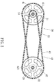
Fig. 2 is a front view of the damping transmission device ofFig. 1 ; -
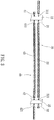
Fig. 3 is a top view of the damping transmission device ofFig. 1 ; -
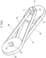
Fig. 4 is a perspective view of a damping transmission device according to a second embodiment of the present invention; -
Fig. 5 is a front view of the damping transmission device ofFig. 4 ; -
Fig. 6 is a top view of the damping transmission device ofFig. 4 ; -
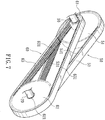
Fig. 7 is a perspective view of a damping transmission device according to a third embodiment of the present invention; and -
Fig. 8 is a front view of the damping transmission device ofFig. 7 . - The present invention will now be described with some preferred embodiments thereof and by referring to the accompanying drawings. For the purpose of easy to understand, elements that are the same in the preferred embodiments are denoted by the same reference numerals. Please refer to
Figs. 1 to 3 . A damping transmission device according to a first embodiment of the present invention includes adriving shaft 10, a drivenshaft 20, afirst transmission mechanism 30 and asecond transmission mechanism 40. Thedriving shaft 10 drives the drivenshaft 20 to rotate via thefirst transmission mechanism 30 and thesecond transmission mechanism 40. - The
first transmission mechanism 30 includes a firstdriving wheel 31, a first drivenwheel 32 and afirst transmission element 33. The firstdriving wheel 31 has an outer diameter larger than that of the first drivenwheel 32. In practical implementation of the present invention, thefirst driving wheel 31 can have an outer diameter that is twice to three times as large as the outer diameter of the first drivenwheel 32. Thefirst transmission element 33 is in the form of a loop wound on thefirst driving wheel 31 and the first drivenwheel 32, so that the first drivingwheel 31 can drive the first drivenwheel 32 to rotate via thefirst transmission element 33. Thefirst transmission mechanism 30 is a low-torque, high-speed transmission mechanism, which enables a bicycle to accelerate faster. - The
second transmission mechanism 40 includes a seconddriving wheel 41, a second drivenwheel 42 and asecond transmission element 43. The second drivenwheel 42 has an outer diameter larger than that of the seconddriving wheel 41. In practical implementation of the present invention, the second drivenwheel 42 can have an outer diameter that is twice to three times as large as the outer diameter of the seconddriving wheel 41. Thesecond transmission element 43 is in the form of a loop wound on the seconddriving wheel 41 and the second drivenwheel 42, so that the seconddriving wheel 41 can drive the second drivenwheel 42 to rotate via thesecond transmission element 43. Thesecond transmission mechanism 40 is a high-torque, low-speed transmission mechanism, which enables a bicycle rider to pedal the bicycle in a labor-saving manner. - In the first embodiment, the
first driving wheel 31, thesecond driving wheel 41, the first drivenwheel 32 and the second drivenwheel 42 are sprocket wheels; and thefirst transmission element 33 and thesecond transmission element 43 are transmission chains. - The
first driving wheel 31 and thesecond driving wheel 41 are mounted on the drivingshaft 10. The drivingshaft 10 drives the first or thesecond driving wheel shaft 10 to automatically select to drive thefirst driving wheel 31 or thesecond driving wheel 41 according to a needed transmission torque. Thefirst driving wheel 31 has an outer diameter larger than that of thesecond driving wheel 41. In practical implementation of the present invention, thefirst driving wheel 31 can have an outer diameter that is twice to three times as large as the outer diameter of thesecond driving wheel 41. - The first driven
wheel 32 and the second drivenwheel 42 are mounted on the drivenshaft 20. The first drivenwheel 32 drives the drivenshaft 20 to rotate. The second drivenwheel 42 can also drive the drivenshaft 20 to rotate. The second drivensprocket wheel 42 has an outer diameter larger than that of the first drivensprocket wheel 32. In practical implementation of the present invention, the second drivensprocket wheel 42 can have an outer diameter that is twice to three times as large as the outer diameter of the first drivensprocket wheel 32. - A first one-
way bearing 311 is mounted between thefirst driving wheel 31 and the drivingshaft 10 for the drivingshaft 10 to drive thefirst driving wheel 31 to rotate in only one direction. A second one-way bearing 411 is mounted between thesecond driving wheel 41 and the drivingshaft 10 for the drivingshaft 10 to drive thesecond driving wheel 41 to rotate in only one direction. - A third one-
way bearing 321 is mounted between the first drivenwheel 32 and the drivenshaft 20 for the first drivenwheel 32 to drive the drivenshaft 20 to rotate in only one direction. A fourth one-way bearing 421 is mounted between the second drivenwheel 42 and the drivenshaft 20 for the second drivenwheel 42 to drive the drivenshaft 20 to rotate in only one direction. - In the present invention, the
first transmission mechanism 30 and thesecond transmission mechanism 40 are combined to constitute a transmission device having a damping effect. The damping transmission device of the present invention in operation automatically selects thefirst transmission mechanism 30 or thesecond transmission mechanism 40 according to the torque and speed needed at the time of riding. For example, (1) when a rider starts pedaling the bicycle, i.e. when the bicycle is changed from a static state into a dynamic state, and a relatively high output torque is needed, the damping transmission device of the present invention will automatically select thesecond transmission mechanism 40 to produce a relatively high transmission torque, allowing the rider to pedal the bicycle in a labor-saving manner; (2) when the rider wants to ride at a higher speed and a lower output torque is required, the damping transmission device of the present invention will automatically select thefirst transmission mechanism 30 to timely enable an increased bicycle speed that is several times faster than the bicycle speed available with thesecond transmission mechanism 40; and (3) when the rider rides on a rough road and the bicycle speed is decreased instantly due to an increased tire rolling resistance on the rough road that necessitates the rider to make more effort to keep the bicycle moving forward, the damping transmission device of the present invention will instantly automatically select thesecond transmission mechanism 40 to timely produce a higher transmission torque, allowing the rider to pedal the bicycle in a labor-saving manner; and when the bicycle speed is increased later, the damping transmission device of the present invention will automatically select thefirst transmission mechanism 30 again. In brief, the damping transmission device can automatically switch between the first and thesecond transmission mechanism shaft 10 can be automatically increased or decreased in response to a reaction force of the road surface, allowing the rider to drive the bicycle in a labor-saving manner. This kind of change in torque is a damping effect. - In practical use of the present invention, when the damping transmission device automatically selects the
second transmission mechanism 40 with high output torque, the first drivenwheel 32 and thefirst transmission chain 33 of thefirst transmission mechanism 30 gradually become static to exert a backward pull on thefirst driving wheel 31, causing a reduced rotational speed of thefirst driving wheel 31. However, it is noted a reverse rotation of the firstdriving sprocket wheel 31 would not bring the drivingshaft 10 to rotate. Similarly, when the damping transmission device automatically selects thefirst transmission mechanism 30 with high output rotational speed, the second drivenwheel 42 and thesecond transmission chain 43 of thesecond transmission mechanism 40 gradually become static to exert a backward pull on thesecond driving wheel 41, causing a reduced rotational speed of the seconddriving sprocket wheel 41. However, it is noted a reverse rotation of the seconddriving sprocket wheel 41 would not bring the drivingshaft 10 to rotate. -
Figs. 4 to 6 show a second embodiment of the present invention that can be applied to electric bicycles and motorcycles. The damping transmission device according to the second embodiment of the present invention includes a drivingshaft 10, a drivenshaft 20, afirst transmission mechanism 50, and asecond transmission mechanism 60. The drivingshaft 10 drives the drivenshaft 20 to rotate via thefirst transmission mechanism 50 and thesecond transmission mechanism 60. - The
first transmission mechanism 50 includes a firstdriving belt wheel 51, a first drivenbelt wheel 52 and afirst transmission belt 53. The firstdriving belt wheel 51 has an outer diameter larger than that of the first drivenbelt wheel 52. In practical implementation of the present invention, the firstdriving belt wheel 51 can have an outer diameter that is three times as large as the outer diameter of the first drivenbelt wheel 52. Thefirst transmission belt 53 is in the form of a loop wound on the firstdriving belt wheel 51 and the first drivenbelt wheel 52, so that the firstdriving belt wheel 51 can drive the first drivenbelt wheel 52 to rotate via thefirst transmission belt 53. Thefirst transmission mechanism 50 is a low-torque, high-speed transmission mechanism. - The
second transmission mechanism 60 includes a seconddriving belt wheel 61, a second drivenbelt wheel 62 and asecond transmission belt 63. The second drivenbelt wheel 62 has an outer diameter larger than that of the seconddriving belt wheel 61. In practical implementation of the present invention, the second drivenbelt wheel 62 can have an outer diameter that is three times as large as the outer diameter of the seconddriving belt wheel 61. Thesecond transmission belt 63 is in the form of a loop wound on the seconddriving belt wheel 61 and the second drivenbelt wheel 62, so that the seconddriving belt wheel 61 can drive the second drivenbelt wheel 62 to rotate via thesecond transmission belt 63. Thesecond transmission mechanism 60 is a high-torque, low-speed transmission mechanism. - A fifth one-
way bearing 511 is mounted between the firstdriving belt wheel 51 and the drivingshaft 10 for the drivingshaft 10 to drive the firstdriving belt wheel 51 to rotate in only one direction. A sixth one-way bearing 611 is mounted between the seconddriving belt wheel 61 and the drivingshaft 10 for the drivingshaft 10 to drive the seconddriving belt wheel 61 to rotate in only one direction. - A seventh one-
way bearing 521 is mounted between the first drivenbelt wheel 52 and the drivenshaft 20 for the first drivenbelt wheel 52 to drive the drivenshaft 20 to rotate in only one direction. An eighth one-way bearing 621 is mounted between the second drivenbelt wheel 62 and the drivenshaft 20 for the second drivenbelt wheel 62 to drive the drivenshaft 20 to rotate in only one direction. -
Figs. 7 and8 show a third embodiment of the present invention, which is a variation of the second embodiment. In the third embodiment, the firstdriving belt wheel 51 and the first drivenbelt wheel 52 of thefirst transmission mechanism 50 have a plurality oftransverse grooves driving belt wheel 51 and the first drivenbelt wheel 52 respectively have a toothed circumferential surface. Further, thefirst transmission belt 53 has a plurality oftransverse ridges 531 equally spaced along its inner side surface. Theridges 531 on thefirst transmission belt 53 sequentially engage with thegrooves driving belt wheel 51 and the first drivenbelt wheel 52 to transmit an even higher transmission torque. - The second
driving belt wheel 61 and the second drivenbelt wheel 62 of thesecond transmission mechanism 60 have a plurality oftransverse grooves driving belt wheel 61 and the second drivenbelt wheel 62 respectively have a toothed circumferential surface. Thesecond transmission belt 63 has a plurality oftransverse ridges 631 equally spaced along its inner side surface. Theridges 631 on thesecond transmission belt 63 sequentially engage with thegrooves driving belt wheel 61 and the second drivenbelt wheel 62 to transmit an even higher transmission torque. - In summary, the damping transmission device according to the present invention combines and automatically switches between the
first transmission mechanism second transmission mechanism - The present invention has been described with some preferred embodiments thereof and it is understood that many changes and modifications in the described embodiments can be carried out without departing from the scope and the spirit of the invention that is intended to be limited only by the appended claims.
Claims (7)
- A damping transmission device, comprising:a driving shaft;a driven shaft;a first transmission mechanism including a first driving wheel, a first driven wheel and a first transmission element; the first driving wheel having an outer diameter larger than that of the first driven wheel; the first transmission element being in the form of a loop wound on the first driving wheel and the first driven wheel for the first driving wheel to drive the first driven wheel to rotate via the first transmission element; the first driving wheel being mounted on the driving shaft with a one-way bearing mounted between the first driving wheel and the driving shaft, such that the driving shaft drives the first driving wheel to rotate in only one direction; and the first driven wheel being mounted on the driven shaft with a one-way bearing mounted between the first driven wheel and the driven shaft, such that the first driven wheel drives the driven shaft to rotate in only one direction; anda second transmission mechanism including a second driving wheel, a second driven wheel and a second transmission element; the second driving wheel having an outer diameter smaller than that of the second driven wheel; the second transmission element being in the form of a loop wound on the second driving wheel and the second driven wheel for the second driving wheel to drive the second driven wheel to rotate via the second transmission element; the second driving wheel being mounted on the driving shaft with a one-way bearing mounted between the second driving wheel and the driving shaft, such that the driving shaft drives the second driving wheel to rotate in only one direction; and the second driven wheel being mounted on the driven shaft with a one-way bearing mounted between the second driven wheel and the driven shaft, such that the second driven wheel drives the driven shaft to rotate in only one direction.
- The damping transmission device as claimed in claim 1, wherein the first driving wheel of the first transmission mechanism has an outer diameter that is twice to three times as large as an outer diameter of the first driven wheel.
- The damping transmission device as claimed in claim 1, wherein the second driven wheel of the second transmission mechanism has an outer diameter that is twice to three times as large as an outer diameter of the second driving wheel.
- The damping transmission device as claimed in claim 1, wherein the first driving wheel, the second driving wheel, the first driven wheel and the second driven wheel are sprocket wheels; and the first transmission element and the second transmission element are transmission chains.
- The damping transmission device as claimed in claim 1, wherein the first driving wheel, the second driving wheel, the first driven wheel and the second driven wheel are belt wheels; and the first transmission element and the second transmission element are transmission belts respectively in the form of a loop.
- The damping transmission device as claimed in claim 5, wherein the first driving belt wheel and the first driven belt wheel of the first transmission mechanism have a plurality of transverse grooves equally spaced along their respective circumferential surfaces and accordingly have a toothed circumferential surface each, and the first transmission belt has a plurality of transverse ridges equally spaced along its inner side surface; and the ridges on the first transmission belt sequentially engaging with the grooves on the first driving belt wheel and the first driven belt wheel.
- The damping transmission device as claimed in claim 5, wherein the second driving belt wheel and the second driven belt wheel of the second transmission mechanism have a plurality of transverse grooves equally spaced along their respective circumferential surfaces and accordingly have a toothed circumferential surface each, and the second transmission belt has a plurality of transverse ridges equally spaced along its inner side surface; and the ridges on the second transmission belt sequentially engaging with the grooves on the second driving belt wheel and the second driven belt wheel.
Applications Claiming Priority (1)
| Application Number | Priority Date | Filing Date | Title |
|---|---|---|---|
| CN201611116210.2A CN108163131B (en) | 2016-12-07 | 2016-12-07 | Damping transmission device |
Publications (1)
| Publication Number | Publication Date |
|---|---|
| EP3333455A1 true EP3333455A1 (en) | 2018-06-13 |
Family
ID=60182423
Family Applications (1)
| Application Number | Title | Priority Date | Filing Date |
|---|---|---|---|
| EP17198145.9A Withdrawn EP3333455A1 (en) | 2016-12-07 | 2017-10-24 | Damping transmission device |
Country Status (2)
| Country | Link |
|---|---|
| EP (1) | EP3333455A1 (en) |
| CN (1) | CN108163131B (en) |
Families Citing this family (1)
| Publication number | Priority date | Publication date | Assignee | Title |
|---|---|---|---|---|
| WO2022097164A1 (en) * | 2020-11-03 | 2022-05-12 | Patil Dharmaraj | Variable speed cycle |
Citations (4)
| Publication number | Priority date | Publication date | Assignee | Title |
|---|---|---|---|---|
| DE2339014A1 (en) * | 1972-10-02 | 1974-04-25 | Fmc Corp | TRANSMISSION |
| DE4310058A1 (en) * | 1993-03-27 | 1994-10-06 | Roland Man Druckmasch | Device for advancing a stream of products |
| EP1564127A1 (en) * | 2004-02-10 | 2005-08-17 | HONDA MOTOR CO., Ltd. | Chain Alignment structure of bicycle transmission |
| CN201884583U (en) * | 2010-11-24 | 2011-06-29 | 黄淳权 | Speed-changing device |
Family Cites Families (6)
| Publication number | Priority date | Publication date | Assignee | Title |
|---|---|---|---|---|
| CN2076071U (en) * | 1990-05-28 | 1991-05-01 | 范桥 | Dual-gear and dual-chain speed variable arrangement of bicycle |
| FR2711351B1 (en) * | 1993-10-20 | 1995-11-17 | Lenoble Jean Paul | Gear shift with manual or automatic differential selection for pedal vehicle. |
| CN2194862Y (en) * | 1994-04-07 | 1995-04-19 | 吴启栋 | Speed-change transmission for bicycle |
| CN2361554Y (en) * | 1999-03-17 | 2000-02-02 | 秦利 | Double-chain automatic speed-changing device for non-automotive vehicle |
| CN2422217Y (en) * | 2000-05-06 | 2001-03-07 | 王学章 | Chair or leather belt transmission type composite power tricycle |
| CN206511064U (en) * | 2016-12-07 | 2017-09-22 | 徐夫子 | damping transmission device |
-
2016
- 2016-12-07 CN CN201611116210.2A patent/CN108163131B/en not_active Expired - Fee Related
-
2017
- 2017-10-24 EP EP17198145.9A patent/EP3333455A1/en not_active Withdrawn
Patent Citations (4)
| Publication number | Priority date | Publication date | Assignee | Title |
|---|---|---|---|---|
| DE2339014A1 (en) * | 1972-10-02 | 1974-04-25 | Fmc Corp | TRANSMISSION |
| DE4310058A1 (en) * | 1993-03-27 | 1994-10-06 | Roland Man Druckmasch | Device for advancing a stream of products |
| EP1564127A1 (en) * | 2004-02-10 | 2005-08-17 | HONDA MOTOR CO., Ltd. | Chain Alignment structure of bicycle transmission |
| CN201884583U (en) * | 2010-11-24 | 2011-06-29 | 黄淳权 | Speed-changing device |
Also Published As
| Publication number | Publication date |
|---|---|
| CN108163131A (en) | 2018-06-15 |
| CN108163131B (en) | 2020-07-03 |
Similar Documents
| Publication | Publication Date | Title |
|---|---|---|
| JP6577600B2 (en) | Conversion device from reciprocating linear motion to unidirectional circular motion and vehicle using the device | |
| JP2002509054A (en) | Bicycle hub drive direction switching device | |
| KR100491743B1 (en) | The moment of aforce transmission apparatus for bicycle | |
| KR101088799B1 (en) | A transmission | |
| US10800486B2 (en) | Damping transmission device | |
| KR100915378B1 (en) | Speed change hub for bicycle | |
| EP3333455A1 (en) | Damping transmission device | |
| JP5120901B2 (en) | Transmission for both motor and pedaling | |
| JP5065264B2 (en) | Bicycle shifting hub | |
| KR20110123851A (en) | Accelerator for bicycle for driving speed elevation | |
| EP4247699A1 (en) | Gear system, pedal cycle, and method of retrofitting gear system | |
| US3147641A (en) | Dual speed hub | |
| KR20110043559A (en) | Power transmission apparatus for bicycle,pedal-boat and chain gear | |
| KR200433316Y1 (en) | The Power-transmission device of Chainless bicycle | |
| KR101793789B1 (en) | Muti-range bycycle | |
| CN101274659A (en) | Centre shaft stepless automatic speed transmission | |
| WO2013191572A1 (en) | Planetary gearbox | |
| DK181416B1 (en) | Electric Pedal Assist Bicycle Powertrain and a Bicycle with the Powertrain | |
| CN200988562Y (en) | Bicycle chain power transfer structure | |
| KR20120080371A (en) | Automatic continuously variable transmission of bicycle | |
| CN203581303U (en) | Bicycle reverse stepping speed changer | |
| KR100956067B1 (en) | Power transmission for bicycle | |
| GB2620726A (en) | Improved power train | |
| KR20170006386A (en) | multi stage gear electric bike | |
| KR20090039699A (en) | Power transmission apparatus for bicycle and pedal-boat |
Legal Events
| Date | Code | Title | Description |
|---|---|---|---|
| PUAI | Public reference made under article 153(3) epc to a published international application that has entered the european phase |
Free format text: ORIGINAL CODE: 0009012 |
|
| STAA | Information on the status of an ep patent application or granted ep patent |
Free format text: STATUS: THE APPLICATION HAS BEEN PUBLISHED |
|
| AK | Designated contracting states |
Kind code of ref document: A1 Designated state(s): AL AT BE BG CH CY CZ DE DK EE ES FI FR GB GR HR HU IE IS IT LI LT LU LV MC MK MT NL NO PL PT RO RS SE SI SK SM TR |
|
| AX | Request for extension of the european patent |
Extension state: BA ME |
|
| STAA | Information on the status of an ep patent application or granted ep patent |
Free format text: STATUS: REQUEST FOR EXAMINATION WAS MADE |
|
| 17P | Request for examination filed |
Effective date: 20181212 |
|
| RBV | Designated contracting states (corrected) |
Designated state(s): AL AT BE BG CH CY CZ DE DK EE ES FI FR GB GR HR HU IE IS IT LI LT LU LV MC MK MT NL NO PL PT RO RS SE SI SK SM TR |
|
| STAA | Information on the status of an ep patent application or granted ep patent |
Free format text: STATUS: EXAMINATION IS IN PROGRESS |
|
| 17Q | First examination report despatched |
Effective date: 20200128 |
|
| STAA | Information on the status of an ep patent application or granted ep patent |
Free format text: STATUS: EXAMINATION IS IN PROGRESS |
|
| GRAP | Despatch of communication of intention to grant a patent |
Free format text: ORIGINAL CODE: EPIDOSNIGR1 |
|
| STAA | Information on the status of an ep patent application or granted ep patent |
Free format text: STATUS: GRANT OF PATENT IS INTENDED |
|
| INTG | Intention to grant announced |
Effective date: 20210315 |
|
| INTG | Intention to grant announced |
Effective date: 20210316 |
|
| STAA | Information on the status of an ep patent application or granted ep patent |
Free format text: STATUS: THE APPLICATION IS DEEMED TO BE WITHDRAWN |
|
| 18D | Application deemed to be withdrawn |
Effective date: 20210727 |