EP3333426A1 - Variable pump - Google Patents
Variable pump Download PDFInfo
- Publication number
- EP3333426A1 EP3333426A1 EP16848517.5A EP16848517A EP3333426A1 EP 3333426 A1 EP3333426 A1 EP 3333426A1 EP 16848517 A EP16848517 A EP 16848517A EP 3333426 A1 EP3333426 A1 EP 3333426A1
- Authority
- EP
- European Patent Office
- Prior art keywords
- seal member
- holding portion
- oil
- foreign matter
- vane
- Prior art date
- Legal status (The legal status is an assumption and is not a legal conclusion. Google has not performed a legal analysis and makes no representation as to the accuracy of the status listed.)
- Granted
Links
Images



Classifications
-
- F—MECHANICAL ENGINEERING; LIGHTING; HEATING; WEAPONS; BLASTING
- F04—POSITIVE - DISPLACEMENT MACHINES FOR LIQUIDS; PUMPS FOR LIQUIDS OR ELASTIC FLUIDS
- F04C—ROTARY-PISTON, OR OSCILLATING-PISTON, POSITIVE-DISPLACEMENT MACHINES FOR LIQUIDS; ROTARY-PISTON, OR OSCILLATING-PISTON, POSITIVE-DISPLACEMENT PUMPS
- F04C14/00—Control of, monitoring of, or safety arrangements for, machines, pumps or pumping installations
- F04C14/18—Control of, monitoring of, or safety arrangements for, machines, pumps or pumping installations characterised by varying the volume of the working chamber
- F04C14/22—Control of, monitoring of, or safety arrangements for, machines, pumps or pumping installations characterised by varying the volume of the working chamber by changing the eccentricity between cooperating members
- F04C14/223—Control of, monitoring of, or safety arrangements for, machines, pumps or pumping installations characterised by varying the volume of the working chamber by changing the eccentricity between cooperating members using a movable cam
- F04C14/226—Control of, monitoring of, or safety arrangements for, machines, pumps or pumping installations characterised by varying the volume of the working chamber by changing the eccentricity between cooperating members using a movable cam by pivoting the cam around an eccentric axis
-
- F—MECHANICAL ENGINEERING; LIGHTING; HEATING; WEAPONS; BLASTING
- F01—MACHINES OR ENGINES IN GENERAL; ENGINE PLANTS IN GENERAL; STEAM ENGINES
- F01C—ROTARY-PISTON OR OSCILLATING-PISTON MACHINES OR ENGINES
- F01C21/00—Component parts, details or accessories not provided for in groups F01C1/00 - F01C20/00
- F01C21/08—Rotary pistons
- F01C21/0809—Construction of vanes or vane holders
- F01C21/0818—Vane tracking; control therefor
- F01C21/0854—Vane tracking; control therefor by fluid means
- F01C21/0863—Vane tracking; control therefor by fluid means the fluid being the working fluid
-
- F—MECHANICAL ENGINEERING; LIGHTING; HEATING; WEAPONS; BLASTING
- F01—MACHINES OR ENGINES IN GENERAL; ENGINE PLANTS IN GENERAL; STEAM ENGINES
- F01M—LUBRICATING OF MACHINES OR ENGINES IN GENERAL; LUBRICATING INTERNAL COMBUSTION ENGINES; CRANKCASE VENTILATING
- F01M1/00—Pressure lubrication
- F01M1/16—Controlling lubricant pressure or quantity
-
- F—MECHANICAL ENGINEERING; LIGHTING; HEATING; WEAPONS; BLASTING
- F04—POSITIVE - DISPLACEMENT MACHINES FOR LIQUIDS; PUMPS FOR LIQUIDS OR ELASTIC FLUIDS
- F04C—ROTARY-PISTON, OR OSCILLATING-PISTON, POSITIVE-DISPLACEMENT MACHINES FOR LIQUIDS; ROTARY-PISTON, OR OSCILLATING-PISTON, POSITIVE-DISPLACEMENT PUMPS
- F04C15/00—Component parts, details or accessories of machines, pumps or pumping installations, not provided for in groups F04C2/00 - F04C14/00
- F04C15/0003—Sealing arrangements in rotary-piston machines or pumps
- F04C15/0023—Axial sealings for working fluid
- F04C15/0026—Elements specially adapted for sealing of the lateral faces of intermeshing-engagement type machines or pumps, e.g. gear machines or pumps
-
- F—MECHANICAL ENGINEERING; LIGHTING; HEATING; WEAPONS; BLASTING
- F04—POSITIVE - DISPLACEMENT MACHINES FOR LIQUIDS; PUMPS FOR LIQUIDS OR ELASTIC FLUIDS
- F04C—ROTARY-PISTON, OR OSCILLATING-PISTON, POSITIVE-DISPLACEMENT MACHINES FOR LIQUIDS; ROTARY-PISTON, OR OSCILLATING-PISTON, POSITIVE-DISPLACEMENT PUMPS
- F04C2/00—Rotary-piston machines or pumps
- F04C2/08—Rotary-piston machines or pumps of intermeshing-engagement type, i.e. with engagement of co-operating members similar to that of toothed gearing
- F04C2/10—Rotary-piston machines or pumps of intermeshing-engagement type, i.e. with engagement of co-operating members similar to that of toothed gearing of internal-axis type with the outer member having more teeth or tooth-equivalents, e.g. rollers, than the inner member
-
- F—MECHANICAL ENGINEERING; LIGHTING; HEATING; WEAPONS; BLASTING
- F04—POSITIVE - DISPLACEMENT MACHINES FOR LIQUIDS; PUMPS FOR LIQUIDS OR ELASTIC FLUIDS
- F04C—ROTARY-PISTON, OR OSCILLATING-PISTON, POSITIVE-DISPLACEMENT MACHINES FOR LIQUIDS; ROTARY-PISTON, OR OSCILLATING-PISTON, POSITIVE-DISPLACEMENT PUMPS
- F04C2/00—Rotary-piston machines or pumps
- F04C2/08—Rotary-piston machines or pumps of intermeshing-engagement type, i.e. with engagement of co-operating members similar to that of toothed gearing
- F04C2/10—Rotary-piston machines or pumps of intermeshing-engagement type, i.e. with engagement of co-operating members similar to that of toothed gearing of internal-axis type with the outer member having more teeth or tooth-equivalents, e.g. rollers, than the inner member
- F04C2/102—Rotary-piston machines or pumps of intermeshing-engagement type, i.e. with engagement of co-operating members similar to that of toothed gearing of internal-axis type with the outer member having more teeth or tooth-equivalents, e.g. rollers, than the inner member the two members rotating simultaneously around their respective axes
-
- F—MECHANICAL ENGINEERING; LIGHTING; HEATING; WEAPONS; BLASTING
- F04—POSITIVE - DISPLACEMENT MACHINES FOR LIQUIDS; PUMPS FOR LIQUIDS OR ELASTIC FLUIDS
- F04C—ROTARY-PISTON, OR OSCILLATING-PISTON, POSITIVE-DISPLACEMENT MACHINES FOR LIQUIDS; ROTARY-PISTON, OR OSCILLATING-PISTON, POSITIVE-DISPLACEMENT PUMPS
- F04C2210/00—Fluid
- F04C2210/20—Fluid liquid, i.e. incompressible
- F04C2210/206—Oil
-
- F—MECHANICAL ENGINEERING; LIGHTING; HEATING; WEAPONS; BLASTING
- F04—POSITIVE - DISPLACEMENT MACHINES FOR LIQUIDS; PUMPS FOR LIQUIDS OR ELASTIC FLUIDS
- F04C—ROTARY-PISTON, OR OSCILLATING-PISTON, POSITIVE-DISPLACEMENT MACHINES FOR LIQUIDS; ROTARY-PISTON, OR OSCILLATING-PISTON, POSITIVE-DISPLACEMENT PUMPS
- F04C2270/00—Control; Monitoring or safety arrangements
- F04C2270/18—Pressure
- F04C2270/185—Controlled or regulated
Definitions
- the present invention relates to a variable oil pump.
- variable oil pump including a pump housing and an adjustment member that adjusts the amount of oil discharged from an oil pump rotor.
- Such a variable oil pump is disclosed in Japanese Patent Laying-Open No. 2014-159761 , for example.
- Japanese Patent Laying-Open No. 2014-159761 discloses a hydraulic controller that controls an oil pump (variable oil pump) including a variable displacement mechanism.
- the oil pump the capacity of which is controlled by the hydraulic controller, described in Japanese Patent Laying-Open No. 2014-159761 includes a housing and an adjustment ring (adjustment member) that rotatably holds a driven rotor housed in the housing from the outer peripheral side.
- the adjustment ring is displaced due to hydraulic pressure, and hence the rotational center of the driven rotor with respect to the rotational center of a drive rotor is moved such that the discharge amount per rotation of the oil pump can be increased and decreased.
- a hydraulic chamber that applies hydraulic pressure to the adjustment ring is provided between a portion of the outer surface of the adjustment ring and the inner surface of the housing.
- a seal member that prevents oil leakage to the outside of the hydraulic chamber is disposed on a contact portion between the adjustment ring and the housing.
- the seal member is fitted into a recess (seal member holding portion) formed on the outer surface of the adjustment ring.
- the seal member is held slidably with respect to the inner surface of the recess, and a tip of the seal member is pressed against the inner surface of the housing with a predetermined pressing force.
- Patent Document 1 Japanese Patent Laying-Open No. 2014-159761
- the present invention has been proposed in order to solve the aforementioned problem, and an object of the present invention is to provide a variable oil pump capable of significantly reducing or preventing impairment of the mobility of a seal member held by a seal member holding portion due to inflow of foreign matter contained in oil into the seal member holding portion.
- a variable oil pump includes a pump housing, an oil pump rotor housed in the pump housing and rotationally driven, an adjustment member housed in the pump housing and that adjusts an amount of oil discharged from the oil pump rotor by being displaced under hydraulic pressure supplied to a hydraulic chamber between the pump housing and the oil pump rotor in a state where the oil pump rotor is rotatably held from an outer peripheral side, a seal member provided in a portion where the adjustment member and the pump housing face each other and that seals oil leakage to an outside of the hydraulic chamber, a seal member holding portion provided in the adjustment member and that holds the seal member, and an oil passage provided in the adjustment member and through which the hydraulic pressure in the hydraulic chamber is drawn into the seal member holding portion.
- the adjustment member is provided with the seal member holding portion that holds the seal member and the oil passage through which the hydraulic pressure in the hydraulic chamber is drawn into the seal member holding portion.
- the oil passage preferably extends in a groove shape from a side of a tip of the seal member that slides with respect to an inner surface of the pump housing toward a root of the seal member held by the seal member holding portion.
- a wall of the seal member holding portion other than the groove-like oil passage can separate the outside (hydraulic chamber side) of the seal member holding portion from the inside (the side on which the seal member slides) of the seal member holding portion formed with the oil passage that extends in a groove shape. Therefore, when the oil in the hydraulic chamber is drawn into the seal member holding portion from a gap between the inner surface of the pump housing and a tip (an entrance of the oil passage) of the seal member holding portion, only the oil is allowed to flow through the oil passage, and the foreign matter in the hydraulic chamber can be prevented from flowing through the oil passage as much as possible. Consequently, the foreign matter can be prevented from being trapped between the seal member holding portion and the seal member as much as possible.
- the seal member holding portion preferably includes a foreign matter storage portion formed in a vicinity of a root of the seal member and that stores foreign matter contained in the oil drawn from the hydraulic chamber and that flows through the oil passage.
- the foreign matter storage portion is preferably formed in the seal member holding portion so as to extend in a thickness direction of the seal member perpendicular to a direction in which the oil passage extends, and a sectional area of the foreign matter storage portion in a direction perpendicular to a direction in which the foreign matter storage portion extends is preferably larger than a sectional area of the oil passage in a direction perpendicular to the direction in which the oil passage extends.
- the foreign matter storage portion (having the sectional area) that is a space larger than the oil passage can easily store the foreign matter. Therefore, even when the foreign matter is drawn into the oil passage, the mobility (slidability) of the seal member can be reliably maintained.
- the aforementioned structure in which the seal member holding portion includes the foreign matter storage portion preferably further includes an urging member disposed on the seal member holding portion and that urges the seal member toward an inner surface of the pump housing by pressing the root, and the foreign matter storage portion is preferably provided between the oil passage and the urging member.
- the foreign matter storage portion is provided between the oil passage and the urging member, and hence it is possible to significantly reduce or prevent the foreign matter reaching a position where the urging member is disposed. That is, a state where the urging member does not properly function due to the foreign matter that remains in the vicinity of the urging member and the seal member is not properly pressed against the inner surface of the pump housing can be avoided. Consequently, even when the foreign matter is drawn into the oil passage, the seal member can be properly pressed against the inner surface of the pump housing, and hence the sealing performance (function of preventing oil leakage to the outside of the hydraulic chamber) of the seal member can be kept high.
- the seal member holding portion preferably slidably sandwiches both side surfaces of the seal member
- the foreign matter storage portion is preferably provided in the vicinity of the root corresponding to each of one side surface and the other side surface of the seal member with the urging member as a center.
- the foreign matter in the hydraulic chamber when drawn into the seal member holding portion via the oil passage, the foreign matter can escape to and be stored in at least one of the foreign matter storage portion on the one side surface side provided between the oil passage and the urging member and the foreign matter storage portion disposed on the opposite side (the other side surface side) with reference to the urging member. Therefore, the foreign matter does not remain in the urging member and the vicinity thereof, and hence the sealing performance of the seal member can be reliably maintained.
- the foreign matter storage portion preferably passes through the seal member holding portion along a thickness direction of the seal member.
- the volume of the foreign matter storage portion can be maximized, and hence even if the foreign matter is gradually accumulated, the foreign matter can be stored in the foreign matter storage portion with a margin. Therefore, the mobility of the vane held by the vane holding portion can be maintained over a long period of time.
- the oil passage is preferably formed in a region where the seal member holding portion faces the pump housing on each of one side and the other side in a thickness direction of the seal member holding portion.
- the oil passage is provided on each of one side and the other side in the thickness direction of the vane holding portion, and hence the oil can be sufficiently drawn into the vane holding portion. Furthermore, even if the drawn foreign matter escapes to the oil passage on one side and flow of the oil is almost reduced, the oil can be drawn from the oil passage on the other side, and hence the oil can be reliably drawn into the vane holding portion.
- variable oil pump 100 according to a first embodiment is now described with reference to Figs. 1 to 8 .
- variable oil pump 100 As shown in Fig. 1 , the variable oil pump 100 according to the first embodiment of the present invention is mounted on an automobile (not shown) including an engine 90.
- the variable oil pump 100 has a function of pumping oil (engine oil) 1 in an oil pan 91 to movable portions (sliding portions) such as a plurality of pistons 92, a crankshaft 93, and a valve mechanism 94.
- the variable oil pump 100 includes a housing (an example of a pump housing) 10, a pump rotor (an example of an oil pump rotor) 20 rotatably provided in the housing 10, an adjustment ring 30 (an example of an adjustment member) that rotatably holds the pump rotor 20 from the outer peripheral side, a coil spring 60 (see Fig. 3 ) that urges the adjustment ring 30 toward its initial position, and a cover 19 (see Fig. 1 ) that covers the housing 10 in an arrow X1 direction from an X2 side.
- the pump rotor 20 includes an inner rotor 21 of an external gear and an outer rotor 22 of an internal gear.
- the rotational center of the inner rotor 21 is decentered by a fixed amount with respect to the rotational center of the outer rotor 22.
- the inner rotor 21 rotates in an arrow R1 direction (clockwise direction)
- the inner rotor 21 rotates with a slight delay in the same direction.
- external teeth 21a of the inner rotor 21 mesh with internal teeth 22a of the outer rotor 22.
- the number of the external teeth 21a of the inner rotor 21 is one less than the number of the internal teeth 22a of the outer rotor 22, and hence a volume chamber V is gradually formed between the inner rotor 21 and the outer rotor 22. Furthermore, the volume chamber V expands and contracts as the pump rotor 20 rotationally moves in the arrow R1 direction such that a pumping function is created in the pump rotor 20.
- the external teeth 21a of the inner rotor 21 each have a tooth profile in which the tooth width is narrowed and the tooth length is stretched radially outward as compared with external teeth of an inner rotor in a common trochoid pump.
- the internal teeth 22a of the outer rotor 22 match the tooth profile of the external teeth 21a to mesh therewith such that a larger volume of the volume chamber V formed in the pump rotor 20 is ensured.
- variable oil pump 100 is disposed obliquely downward with respect to the crankshaft 93 inside a crankcase 95.
- a vertically long chain cover (timing chain cover) 96 is fastened to a side end surface of an engine block 90a on the X2 side, and a region (Z2 side) of a lower end of the chain cover 96 is fastened to a side end surface of the oil pan 91 in the crankcase 95.
- An end of the crankshaft 93 on the X2 side is exposed to the outside (X2 side) via an oil seal (not shown) fitted into a through-hole of the chain cover 96, and a crank pulley 97 is attached to this portion.
- variable oil pump 100 is disposed inside the chain cover 96, and a timing chain 99 is wound around the crankshaft 93 and a sprocket 98 on the side of an input shaft 55.
- the drive force of the crankshaft 93 is transmitted to the input shaft 55 via the timing chain 99 and the sprocket 98 both for driving the oil pump, and the pump rotor 20 is rotated by the input shaft 55 pressed into the inner rotor 21.
- the housing 10 is a concave (deep dish-shaped) casting of an aluminum alloy, and includes a circumferential wall 11 that surrounds the outer edge of the housing 10 and a bottom 12 that connects the wall 11. Furthermore, in a state where the pump rotor 20, the adjustment ring 30, and the coil spring 60 (see Fig. 3 ) are housed in a concave housing recess 12c defined by the wall 11 and the bottom 12 in a predetermined positional relationship, the cover 19 (see Fig. 1 ) is attached.
- the housing 10 is provided with a suction port 13 through which the oil 1 (see Fig. 1 ) is suctioned and a discharge port 14 through which the oil 1 (see Fig. 1 ) is discharged.
- suction port 13 is connected to a pipe 3 (see Fig. 4 ) connected to an oil strainer 2 via an oil passage 13b inside the housing 10 from an opening 13a opened in the bottom 12, a downstream portion 13c is formed in a shallow groove shape by recessing the bottom 12 according to a suction range.
- the discharge port 14 is formed in a shallow groove shape by recessing the bottom 12 according to a discharge range, and is connected to a discharge oil passage 4 (see Fig. 4 ) via an oil passage 14a inside the housing 10.
- the housing 10 includes two pins 15 and 16 that protrude in an X-axis direction from the bottom 12.
- the pins 15 and 16 include outer surfaces 15a and 16a circularly formed.
- the pins 15 and 16 are configured to engage with guide holes 38 and 39 of the adjustment ring 30 described later, respectively.
- the cover 19 (see Fig. 1 ) is fastened to a joint surface 11b (an end surface on the X2 side) of the wall 11 of the housing 10 in the arrow X1 direction from the X2 side in Fig. 2 by a fastening member (not shown).
- the variable oil pump 100 includes a variable displacement mechanism to change the discharge amount (pump capacity) of the oil 1 discharged every rotation of the pump rotor 20.
- This variable displacement mechanism is a mechanism that displaces (rotates) the adjustment ring 30 due to hydraulic pressure (control hydraulic pressure) in a hydraulic chamber U formed in the housing recess 12c of the housing 10.
- the relative positions of the inner rotor 21 and the outer rotor 22 with respect to the suction port 13 and the discharge port 14 are changed due to the displacement (rotation) of the adjustment ring 30, and the pump capacity is changed.
- the variable displacement mechanism including the adjustment ring 30 is described below in detail.
- the adjustment ring 30 includes a main body 31, overhangs 32 and 33, an operation portion 34, and a protrusion 35.
- the overhangs 32 and 33, the operation portion 34, and the protrusion 35 are integral with the main body 31.
- the pump rotor 20 is disposed such that its outer peripheral surface 20a smoothly contacts (slides with respect to) the inner peripheral surface 31a of the main body 31.
- the main body 31 is annular, and has a function of rotatably holding the pump rotor 20 (outer rotor 22) from the outer peripheral side.
- the outer surface 31b of the main body 31 overhangs outward (in an outward radial direction of rotation) such that the overhangs 32 and 33 are formed.
- the overhang 32 is formed with the elongated hole-shaped guide hole 38 that penetrates in a thickness direction (X-axis direction), and the overhang 33 is formed with the elongated hole-shaped guide hole 39 that penetrates in the thickness direction.
- the operation portion 34 protrudes from the outer surface 31b, and an external force (the hydraulic pressure in the hydraulic chamber U or the urging force of the coil spring 60) is applied thereto when the main body 31 rotates.
- a vane holding portion 34a (an example of a seal member holding portion), which includes a concavely recessed tip, of the operation portion 34 holds a vane 41 (an example of a seal member) via a leaf spring 61 (an example of an urging member).
- the protrusion 35 protrudes from the outer surface 31b, and a vane holding portion 35a (an example of a seal member holding portion) including a concavely recessed tip holds a vane 42 (an example of a seal member) via a leaf spring 61.
- the vanes 41 and 42 have substantially the same length as the thickness (a dimension in the X-axis direction) of the adjustment ring 30, and are made of a resin material or the like excellent in wear resistance.
- the vane holding portion 34a is provided with oil passages 36 through which the hydraulic pressure in the hydraulic chamber U is drawn into the vane holding portion 34a.
- the vane holding portion 35a is also provided with oil passages 36 through which the hydraulic pressure in the hydraulic chamber U is drawn into the vane holding portion 35a.
- the vane holding portions 34a and 35a each provided with the oil passages 36 basically have the same configuration and function, and hence the vane holding portion 34a continues to be described as a representative.
- the oil passages 36 each extend linearly and in a groove shape from the side of a tip 41a of the vane 41 that slides with respect to the inner surface 11a of the housing 10 toward a root 41b of the vane 41 held by the vane holding portion 34a. Therefore, the vane holding portion 34a is provided with a wall 34b other than the oil passages 36. That is, the wall 34b separates the outside (the hydraulic chamber U side) of the vane holding portion 34a from the inside (the side on which the vane 41 slides) of the vane holding portion 34a where the oil passages 36 that extend in a groove shape are formed. Furthermore, as shown in Figs.
- the oil passages 36 are provided in regions 10a and 10b where the vane holding portion 34a faces the housing 10 on one side (X1 side) and the other side (X2 side) in the thickness direction (X-axis direction) of the vane holding portion 34a, respectively.
- the vane holding portion 35a also has a wall 35b.
- the vane holding portion 34a is further provided with foreign matter storage portions 37 that store foreign matter contained in the oil 1 that flows through the oil passages 36 in addition to the oil passages 36.
- the foreign matter storage portions 37 are formed in the vane holding portion 34a so as to extend in the thickness direction (X-axis direction) of the vane 41 perpendicular to an arrow B2 direction in which the oil passages 36 extend. Furthermore, the foreign matter storage portions 37 pass through the vane holding portion 34a in the thickness direction (X-axis direction).
- the sectional area S2 (see Fig.
- each of the foreign matter storage portions 37 in a Y-Z plane in a direction perpendicular to the X-axis direction in which the foreign matter storage portions 37 extend is larger than the sectional area S1 (a sectional area in a direction along the plane of Fig. 5 ) of each of the oil passages 36 in a direction perpendicular to the arrow B2 direction in which the oil passages 36 extend.
- one of the foreign matter storage portions 37 is provided between the oil passages 36 and the leaf spring 61. Furthermore, the foreign matter storage portions 37 are provided in the vicinity of the root 41b corresponding to one side surface 41c and the other side surface 41d of the vane 41 with the leaf spring 61 as a center, respectively.
- a structure similar to that of the vane holding portion 34a is also provided in the vane holding portion 35a. However, in the vane holding portion 35a, a position where the oil passages 36 are formed is located on the side (the side closer to the hydraulic chamber U) opposite to that of the vane holding portion 34a.
- the oil passages 36 of the vane holding portion 35a extend along the other side surface 42d of the vane 42 on the side that faces the hydraulic chamber U.
- a pair of foreign matter storage portions 37 are provided in the vicinity of a root 42b corresponding to one side surface 42c and the other side surface 42d with the leaf spring 61 as a center.
- a convex portion 151 formed on a jig 110 is inserted into the foreign matter storage portions 37 in a state where the vane 41 (42) and the leaf spring 61 are held by the jig 110 such that the vane 41 (42) and the leaf spring 61 are attached to the vane holding portion 34a (35a) using the foreign matter storage portions 37 as a reference for assembly.
- the coil spring 60 is fitted into a region where the inner surface 11a of the wall 11 faces the operation portion 34 in a state where the adjustment ring 30 is housed in the housing 10.
- the operation portion 34 is urged in an arrow A1 direction due to the extension force of the coil spring 60. That is, due to the pressing force of the coil spring 60 that acts on the operation portion 34, the adjustment ring 30 is urged so as to be rotated (displaced) in the clockwise direction in Fig. 1 about the input shaft 55.
- the adjustment ring 30 is held at the initial position where the adjustment ring 30 starts to be displaced (rotate) in a state where the coil spring 60 is maximally extended.
- the hydraulic chamber U is formed in a region surrounded by the inner surface 11a of the wall 11, the vanes 41 and 42, and the outer surface 31b (including a portion of the outer surface of the operation portion 34) of the adjustment ring 30 between the vanes 41 and 42.
- the pin 15 is slidably inserted into the guide hole 38 and engages therewith, and the pin 16 is slidably inserted into the guide hole 39 and engages therewith.
- the pin 15 and the guide hole 38 engage with each other, and the pin 16 and the guide hole 39 engage with each other such that guide portions 51 and 52 guide relative displacement (rotation) of the adjustment ring 30 with respect to the housing 10.
- the guide portions 51 and 52 restrict a direction in which the adjustment ring 30 rotates to a direction in which the guide holes 38 and 39 extend (the longitudinal direction of the cross-sections of the guide holes 38 and 39).
- a hydraulic controller 5 that allows the variable displacement mechanism of the variable oil pump 100 to operate is provided in the discharge oil passage 4 of the engine 90.
- the variable oil pump 100 and the hydraulic controller 5 are connected to each other by an oil passage 6a that branches from the discharge oil passage 4.
- the hydraulic controller 5 and the hydraulic chamber U in the housing 10 are connected to each other via an oil passage 6b.
- the hydraulic controller 5 operates based on a control signal from an ECU (not shown) mounted on the engine 90 such that the oil 1 delivered from the discharge oil passage 4 to the engine 90 (oil gallery) via an oil filter 7 (see Fig. 1 ) is partially drawn into the hydraulic controller 5 via the oil passage 6a, and then supplied to the hydraulic chamber U via the oil passage 6b.
- Variable displacement control of the amount of the oil 1 discharged by the variable oil pump 100 is now described with reference to Figs. 3 and 8 .
- the pump rotor 20 is driven in the arrow R1 direction by the input shaft 55 that rotates together with the start-up of the engine 90.
- the hydraulic controller 5 does not operate, and the adjustment ring 30 is held at the initial position reached when the adjustment ring 30 is maximally rotated in the arrow A1 direction due to the urging force of the coil spring 60.
- the inner surface 38a (39a) of the guide hole 38 (39) and the outer surface 15a (16a) of the pin 15 (16) contact each other.
- the suction port 13 faces a negative pressure action region where the pressure of the oil 1 is reduced between the external teeth 21a of the inner rotor 21 and the internal teeth 22a of the outer rotor 22, and the discharge port 14 faces a positive pressure action region where the oil 1 is compressed between the external teeth 21a of the inner rotor 21 and the internal teeth 22a of the outer rotor 22. Therefore, the oil 1 is suctioned into the pump rotor 20 from the suction port 13 and is discharged from the discharge port 14 to the discharge oil passage 4 via the oil passage 14a.
- the hydraulic controller 5 operates based on the control signal from the ECU (not shown) according to the rotational speed and load of the engine 90. That is, after the oil 1 from the suction port 13 is drawn into the hydraulic controller 5 via the oil passage 6a, the oil 1 is supplied to the hydraulic chamber U via the oil passage 6b. Then, the hydraulic pressure of the oil 1 supplied to the hydraulic chamber U acts on the operation portion 34 of the adjustment ring 30 such that the adjustment ring 30 starts to rotate in an arrow A2 direction against the urging force of the coil spring 60.
- the outer rotor 22 of the pump rotor 20 revolves in the arrow A2 direction while maintaining a predetermined amount of eccentricity with respect to the rotational center of the inner rotor 21 in a state where the internal teeth 22a mesh with the external teeth 21a of the inner rotor 21.
- the positive pressure action region and the negative pressure action region are moved about the rotational center of the inner rotor 21, and hence the negative pressure that acts on the suction port 13 from the negative pressure action region is reduced, and the positive pressure that acts on the discharge port 14 from the positive pressure action region is also reduced. Consequently, the amount (a supply to the engine 90) of the oil 1 discharged from the pump rotor 20 is reduced.
- the ECU controls the operation of the hydraulic controller 5 in detail such that the hydraulic pressure (the urging force for urging the operation portion 34 in the arrow A2 direction) of the oil 1 supplied to the hydraulic chamber U is adjusted.
- the rotational position of the adjustment ring 30 is precisely adjusted according to the balance relationship between the hydraulic pressure in the hydraulic chamber U with respect to the operation portion 34 and the urging force (the urging force for urging the operation portion 34 in the arrow A1 direction) of the coil spring 60 with respect to the operation portion 34.
- the rotational position of the adjustment ring 30 is adjusted such that the amount of the oil 1 discharged by the variable oil pump 100 is controlled in detail.
- the variable oil pump 100 according to the first embodiment is configured as described above.
- the adjustment ring 30 is provided with the vane holding portion 34a (35a) that holds the vane 41 (42) and the oil passages 36 through which the hydraulic pressure in the hydraulic chamber U is drawn into the vane holding portion 34a (35a).
- the vane holding portion 34a (35a) that holds the vane 41 (42) and the oil passages 36 through which the hydraulic pressure in the hydraulic chamber U is drawn into the vane holding portion 34a (35a).
- the oil passages 36 each extend in a groove shape from the side of the tip 41a (42a) of the vane 41 (42) that slides with respect to the inner surface 11a of the housing 10 toward the root 41b (42b) held by the vane holding portion 34a (35a).
- the wall 34b (35b) of the vane holding portion 34a (35a) other than the groove-like oil passages 36 can separate the outside (hydraulic chamber U side) of the vane holding portion 34a (35a) from the inside (the side on which the vane 41 (42) slides) of the vane holding portion 34a (35a) formed with the oil passages 36 that extend in a groove shape.
- the foreign matter storage portions 37 formed in the vicinity of the root 41b (42b) of the vane 41 (42) and that store the foreign matter contained in the oil 1 drawn from the hydraulic chamber U and that flows through the oil passages 36 are provided in the vane holding portion 34a (35a).
- the foreign matter in the hydraulic chamber U is drawn into the vane holding portion 34a (35a) via the oil passages, the foreign matter can escape to (accumulate in) the foreign matter storage portions 37 formed in the vicinity of the root 41b (42b) of the vane 41 (42), and hence the foreign matter can be effectively prevented from being trapped between the vane holding portion 34a (35a) and the vane 41 (42). Therefore, even when the foreign matter is drawn into the oil passages 36, the mobility (smooth slidability) of the vane 41 (42) can be easily maintained.
- the foreign matter storage portions 37 are formed in the vane holding portion 34a (35a) so as to extend in the thickness direction (X-axis direction) of the vane 41 (42) perpendicular to the arrow B2 direction in which the oil passages 36 extend. Furthermore, the sectional area S1 of each of the foreign matter storage portions 37 in the Y-Z plane is larger than the sectional area S2 (the sectional area in the direction along the plane of Fig. 5 ) of each of the oil passages 36.
- each of the foreign matter storage portions 37 having the sectional area S2 which is a space larger than each of the oil passages 36, can easily store the foreign matter. Therefore, even when the foreign matter is drawn into the oil passages 36, the mobility (smooth slidability) of the vane 41 (42) can be reliably maintained.
- one of the foreign matter storage portions 37 is provided between the oil passages 36 and the leaf spring 61.
- the foreign matter storage portion 37 exists between the oil passages 36 and the leaf spring 61, and hence it is possible to significantly reduce or prevent the foreign matter reaching a position where the leaf spring 61 is disposed. That is, a state where the leaf spring 61 does not properly function due to the foreign matter that remains in the vicinity of the leaf spring 61 and the vane 41 (42) is not properly pressed against the inner surface 11a of the housing 10 can be avoided.
- the vane 41 (42) can be properly pressed against the inner surface 11a of the housing 10, and hence the sealing performance (function of preventing oil leakage to the outside of the hydraulic chamber U) of the vane 41 (42) can be kept high.
- the foreign matter storage portions 37 are provided in the vicinity of the root 41b (42b) corresponding to one side surface 41c (42c) and the other side surface 41d (42d) of the vane 41 (42) with the leaf spring 61 as a center, respectively.
- the foreign matter in the hydraulic chamber U is drawn into the vane holding portion 34a (35a) via the oil passages 36, the foreign matter can escape to and be stored in at least one of the foreign matter storage portion 37 on the one side surface 41c (42c) side provided between the oil passages 36 and the leaf spring 61 and the foreign matter storage portion 37 disposed on the opposite side (the other side surface 41d (42d) side) with reference to the leaf spring 61. Therefore, the foreign matter does not remain in the leaf spring 61 and the vicinity thereof, and hence the sealing performance of the vane 41 (42) can be reliably maintained.
- the oil passages 36 are formed in the regions 10a and 10b where the vane holding portion 34a (35a) faces the housing 10 on one side and the other side in the thickness direction of the vane holding portion 34a (35a), respectively.
- the oil passages 36 are provided on one side and the other side in the thickness direction of the vane holding portion 34a (35a), respectively, and hence the oil 1 can be sufficiently drawn into the vane holding portion 34a (35a).
- the oil 1 can be drawn from the oil passage 36 on the other side, and hence the oil 1 can be reliably drawn into the vane holding portion 34a (35a).
- the foreign matter storage portions 37 pass through the vane holding portion 34a (35a) along the thickness direction of the vane 41 (42).
- the volume of the foreign matter storage portions 37 can be maximized, and hence even if the foreign matter is gradually accumulated, the foreign matter can be stored in the foreign matter storage portions 37 with a margin. Therefore, the mobility of the vane 41 (42) held by the vane holding portion 34a (35a) can be maintained over a long period of time.
- the convex portion 151 formed on the jig 110 is inserted into the foreign matter storage portions 37 in a state where the vane 41 (42) and the leaf spring 61 are held by the jig 110 such that the vane 41 (42) and the leaf spring 61 are assembled to the vane holding portion 34a (35a) using the foreign matter storage portions 37 as a reference for assembly.
- the vane 41 (42) and the leaf spring 61 held by the jig 110 can be easily attached to the vane holding portion 34a (35a) by effectively using the foreign matter storage portions 37 formed in advance in the vane holding portion 34a (35a).
- an adjustment ring 130 includes an operation portion 134 including a vane holding portion 134a (an example of a seal member holding portion).
- the vane holding portion 134a is provided with the oil passages 36 through which hydraulic pressure in a hydraulic chamber U is drawn into the vane holding portion 134a.
- One foreign matter storage portion 37 is formed between the oil passages 36 and the leaf spring 61 that presses a vane 41.
- no foreign matter storage portion 37 is provided in the vicinity of a root 41b beyond the leaf spring 61 in an arrow A2 direction.
- a structure similar to that of the vane holding portion 134a is also applied to a vane holding portion 35a (see Fig. 3 ) corresponding to the aforementioned first embodiment.
- the adjustment ring 130 is provided with the vane holding portion 134a that holds the vane 41 and the oil passages 36 through which the hydraulic pressure in the hydraulic chamber U is drawn into the vane holding portion 134a. Furthermore, one foreign matter storage portion 37 is provided only between the oil passages 36 and the leaf spring 61. As described above, even when the foreign matter storage portion 37 is provided at one location, foreign matter can escape to the oil passages 36 and the foreign matter storage portion 37, and hence the foreign matter can be prevented from being trapped between the vane holding portion 134a and the vane 41. Thus, it is possible to significantly reduce or prevent impairment of the mobility (slidability) of the vane 41 with respect to the vane holding portion 134a.
- a second embodiment is now described with reference to Figs. 1 , 3 , 4 , 10 , and 11 .
- this second embodiment an example in which the shape of oil passages 81 of a variable oil pump 200 is different from that according to the first embodiment is described.
- an adjustment ring 230 incorporated in the variable oil pump 200 includes an operation portion 234 including a vane holding portion 234a (an example of a seal member holding portion).
- the vane holding portion 234a is provided with the oil passages 81 through which hydraulic pressure in a hydraulic chamber U is drawn into the vane holding portion 234a.
- the oil passages 81 are formed by cutting tip regions of the vane holding portion 234a on one side (A1 side) so as to spread flat. Furthermore, as shown in Fig. 11 , the oil passages 81 are provided in regions 10a and 10b where the vane holding portion 234a faces a housing 10 on one side (X1 side) and the other side (X2 side) in the thickness direction (X-axis direction) of the vane holding portion 234a, respectively. In this case, the oil passages 81 are recessed with a depth H1 with respect to the regions 10a and 10b.
- the adjustment ring 230 is provided with the vane holding portion 234a that holds a vane 41 and the oil passages 81 through which the hydraulic pressure in the hydraulic chamber U is drawn into the vane holding portion 234a.
- oil passages 36 (81) are provided in the regions 10a and 10b where the vane holding portion 34a (234a) faces the housing 10 on one side (X1 side) and the other side (X2 side) in the thickness direction (X-axis direction) of the vane holding portion 34a (234a), respectively, in each of the aforementioned first and second embodiments, the present invention is not restricted to this. That is, an oil passage 36 (81) may be provided only in the region 10a or 10b on one side or the other side (X1 side or X2 side) of the vane holding portion 34a.
- oil passages 36 (81) are exposed in the regions 10a and 10b where the vane holding portion 34a (234a) faces the housing 10 in the thickness direction of the vane holding portion 34a (234a) in each of the aforementioned first and second embodiments, the present invention is not restricted to this.
- one oil passage 36 may pass through the member from the tip side of the vane holding portion 34a toward the foreign matter storage portion 37.
- the present invention is not restricted to this.
- a deep hole-like foreign matter storage portion connected to the oil passage 36 and including a bottom that does not break through the other side of the vane holding portion 34a in the X-axis direction may be provided.
- oil passages 81 are provided in the vane holding portion 234a in the aforementioned second embodiment, the present invention is not restricted to this. That is, in addition to the oil passages 81, foreign matter storage portions 37 (see Fig. 4 ) may be further provided in the vicinity of a root 41b (42b) of the vane 41 (42).
- sectional area S1 of each of the foreign matter storage portions 37 is larger than the sectional area S2 of each of the oil passages 36 in each of the aforementioned first embodiment and the modification thereof, the present invention is not restricted to this. That is, the sectional area S1 of each of the foreign matter storage portions 37 and the sectional area S2 of each of the oil passages 36 may be equal to each other.
- the present invention is applied to the variable oil pump 100 that supplies the oil 1 to the engine 90 in each of the aforementioned first and second embodiments, the present invention is not restricted to this.
- the present invention may be applied to an oil pump that supplies AT fluid to an automatic transmission (AT) that automatically switches a transmission gear ratio according to the rotational speed of an engine.
- the present invention may be applied to an oil pump that supplies lubricating oil to a sliding portion in a continuously variable transmission (CVT) that continuously and steplessly changes a transmission gear ratio unlike the AT (multistage transmission), or an oil pump that supplies power steering oil to a power steering that drives a steering.
- CVT continuously variable transmission
- variable oil pump 100 is mounted on the automobile including the engine 90 in each of the aforementioned first and second embodiments, the present invention is not restricted to this.
- the present invention may be applied to a variable oil pump for an internal combustion engine mounted on equipment other than a vehicle.
- a gasoline engine, a diesel engine, a gas engine, etc. can be applied as the internal combustion engine.
- the present invention is not restricted to this. That is, the present invention may be applied to a variable oil pump including an internal gear pump rotor in which the tooth profile of each of external teeth 21a and internal teeth 22a includes a trochoid curve or a cycloid curve.
Landscapes
- Engineering & Computer Science (AREA)
- Mechanical Engineering (AREA)
- General Engineering & Computer Science (AREA)
- Details And Applications Of Rotary Liquid Pumps (AREA)
- Rotary Pumps (AREA)
Abstract
Description
- The present invention relates to a variable oil pump.
- In general, a variable oil pump including a pump housing and an adjustment member that adjusts the amount of oil discharged from an oil pump rotor is known. Such a variable oil pump is disclosed in Japanese Patent Laying-Open No.
2014-159761 - Japanese Patent Laying-Open No.
2014-159761 2014-159761 - Patent Document 1: Japanese Patent Laying-Open No.
2014-159761 - However, in the oil pump (variable oil pump) described in Japanese Patent Laying-Open No.
2014-159761 - The present invention has been proposed in order to solve the aforementioned problem, and an object of the present invention is to provide a variable oil pump capable of significantly reducing or preventing impairment of the mobility of a seal member held by a seal member holding portion due to inflow of foreign matter contained in oil into the seal member holding portion.
- In order to attain the aforementioned object, a variable oil pump according to an aspect of the present invention includes a pump housing, an oil pump rotor housed in the pump housing and rotationally driven, an adjustment member housed in the pump housing and that adjusts an amount of oil discharged from the oil pump rotor by being displaced under hydraulic pressure supplied to a hydraulic chamber between the pump housing and the oil pump rotor in a state where the oil pump rotor is rotatably held from an outer peripheral side, a seal member provided in a portion where the adjustment member and the pump housing face each other and that seals oil leakage to an outside of the hydraulic chamber, a seal member holding portion provided in the adjustment member and that holds the seal member, and an oil passage provided in the adjustment member and through which the hydraulic pressure in the hydraulic chamber is drawn into the seal member holding portion.
- In the variable oil pump according to this aspect of the present invention, as hereinabove described, the adjustment member is provided with the seal member holding portion that holds the seal member and the oil passage through which the hydraulic pressure in the hydraulic chamber is drawn into the seal member holding portion. Thus, even when foreign matter contained in oil flows into the seal member holding portion via the oil passage during operation of the variable oil pump, the foreign matter can escape to the oil passage provided in the adjustment member, and hence the foreign matter can be prevented from being trapped between the seal member holding portion and the seal member. Consequently, it is possible to significantly reduce or prevent impairment of the mobility (slidability) of the seal member held by the seal member holding portion due to the foreign matter contained in the oil and that flows into the seal member holding portion.
- In the aforementioned variable oil pump according to this aspect, the oil passage preferably extends in a groove shape from a side of a tip of the seal member that slides with respect to an inner surface of the pump housing toward a root of the seal member held by the seal member holding portion.
- According to this structure, a wall of the seal member holding portion other than the groove-like oil passage can separate the outside (hydraulic chamber side) of the seal member holding portion from the inside (the side on which the seal member slides) of the seal member holding portion formed with the oil passage that extends in a groove shape. Therefore, when the oil in the hydraulic chamber is drawn into the seal member holding portion from a gap between the inner surface of the pump housing and a tip (an entrance of the oil passage) of the seal member holding portion, only the oil is allowed to flow through the oil passage, and the foreign matter in the hydraulic chamber can be prevented from flowing through the oil passage as much as possible. Consequently, the foreign matter can be prevented from being trapped between the seal member holding portion and the seal member as much as possible.
- In this case, the seal member holding portion preferably includes a foreign matter storage portion formed in a vicinity of a root of the seal member and that stores foreign matter contained in the oil drawn from the hydraulic chamber and that flows through the oil passage.
- According to this structure, when the foreign matter in the hydraulic chamber is drawn into the seal member holding portion via the oil passage, the foreign matter can escape to (accumulate in) the foreign matter storage portion formed in the vicinity of the root of the seal member, and hence the foreign matter can be effectively prevented from being trapped between the seal member holding portion and the seal member. Therefore, even when the foreign matter is drawn into the oil passage, the mobility (slidability) of the seal member can be easily maintained.
- In the aforementioned structure in which the seal member holding portion includes the foreign matter storage portion, the foreign matter storage portion is preferably formed in the seal member holding portion so as to extend in a thickness direction of the seal member perpendicular to a direction in which the oil passage extends, and a sectional area of the foreign matter storage portion in a direction perpendicular to a direction in which the foreign matter storage portion extends is preferably larger than a sectional area of the oil passage in a direction perpendicular to the direction in which the oil passage extends.
- According to this structure, when the foreign matter in the hydraulic chamber is drawn into the seal member holding portion via the oil passage, the foreign matter storage portion (having the sectional area) that is a space larger than the oil passage can easily store the foreign matter. Therefore, even when the foreign matter is drawn into the oil passage, the mobility (slidability) of the seal member can be reliably maintained.
- The aforementioned structure in which the seal member holding portion includes the foreign matter storage portion preferably further includes an urging member disposed on the seal member holding portion and that urges the seal member toward an inner surface of the pump housing by pressing the root, and the foreign matter storage portion is preferably provided between the oil passage and the urging member.
- According to this structure, when the foreign matter in the hydraulic chamber is drawn into the seal member holding portion via the oil passage, the foreign matter storage portion is provided between the oil passage and the urging member, and hence it is possible to significantly reduce or prevent the foreign matter reaching a position where the urging member is disposed. That is, a state where the urging member does not properly function due to the foreign matter that remains in the vicinity of the urging member and the seal member is not properly pressed against the inner surface of the pump housing can be avoided. Consequently, even when the foreign matter is drawn into the oil passage, the seal member can be properly pressed against the inner surface of the pump housing, and hence the sealing performance (function of preventing oil leakage to the outside of the hydraulic chamber) of the seal member can be kept high.
- In this case, the seal member holding portion preferably slidably sandwiches both side surfaces of the seal member, and the foreign matter storage portion is preferably provided in the vicinity of the root corresponding to each of one side surface and the other side surface of the seal member with the urging member as a center.
- According to this structure, when the foreign matter in the hydraulic chamber is drawn into the seal member holding portion via the oil passage, the foreign matter can escape to and be stored in at least one of the foreign matter storage portion on the one side surface side provided between the oil passage and the urging member and the foreign matter storage portion disposed on the opposite side (the other side surface side) with reference to the urging member. Therefore, the foreign matter does not remain in the urging member and the vicinity thereof, and hence the sealing performance of the seal member can be reliably maintained.
- In the aforementioned variable oil pump in which the seal member holding portion includes the foreign matter storage portion, the foreign matter storage portion preferably passes through the seal member holding portion along a thickness direction of the seal member.
- According to this structure, the volume of the foreign matter storage portion can be maximized, and hence even if the foreign matter is gradually accumulated, the foreign matter can be stored in the foreign matter storage portion with a margin. Therefore, the mobility of the vane held by the vane holding portion can be maintained over a long period of time.
- In the aforementioned variable oil pump according to this aspect, the oil passage is preferably formed in a region where the seal member holding portion faces the pump housing on each of one side and the other side in a thickness direction of the seal member holding portion.
- According to this structure, even when the sectional area of the oil passage is small in order to draw only the oil in the hydraulic chamber, the oil passage is provided on each of one side and the other side in the thickness direction of the vane holding portion, and hence the oil can be sufficiently drawn into the vane holding portion. Furthermore, even if the drawn foreign matter escapes to the oil passage on one side and flow of the oil is almost reduced, the oil can be drawn from the oil passage on the other side, and hence the oil can be reliably drawn into the vane holding portion.
-
- [
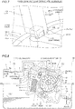
Fig. 1 ] A diagram showing an engine mounted with a variable oil pump according to a first embodiment of the present invention. - [
Fig. 2 ] An exploded perspective view showing the structure of the variable oil pump according to the first embodiment of the present invention. - [
Fig. 3 ] A plan view showing the internal structure of the variable oil pump according to the first embodiment of the present invention. - [
Fig. 4 ] An enlarged perspective view around a vane holding portion of the variable oil pump according to the first embodiment of the present invention. - [
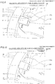
Fig. 5 ] A sectional view taken along the line 150-150 inFig. 4 . - [
Fig. 6 ] A sectional view taken along the line 160-160 inFig. 4 . - [
Fig. 7 ] A diagram showing part of an assembly process of the variable oil pump according to the first embodiment of the present invention. - [
Fig. 8 ] A diagram showing the capacity control state of the variable oil pump according to the first embodiment of the present invention. - [
Fig. 9 ] An enlarged perspective view around a vane holding portion according to a modification of the first embodiment of the present invention. - [
Fig. 10 ] An enlarged perspective view around a vane holding portion of a variable oil pump according to a second embodiment of the present invention. - [
Fig. 11 ] A sectional view taken along the line 250-250 inFig. 10 . - Embodiments of the present invention are hereinafter described on the basis of the drawings.
- A
variable oil pump 100 according to a first embodiment is now described with reference toFigs. 1 to 8 . - As shown in
Fig. 1 , thevariable oil pump 100 according to the first embodiment of the present invention is mounted on an automobile (not shown) including anengine 90. Thevariable oil pump 100 has a function of pumping oil (engine oil) 1 in anoil pan 91 to movable portions (sliding portions) such as a plurality ofpistons 92, a crankshaft 93, and avalve mechanism 94. - As shown in
Fig. 2 , thevariable oil pump 100 includes a housing (an example of a pump housing) 10, a pump rotor (an example of an oil pump rotor) 20 rotatably provided in thehousing 10, an adjustment ring 30 (an example of an adjustment member) that rotatably holds thepump rotor 20 from the outer peripheral side, a coil spring 60 (seeFig. 3 ) that urges theadjustment ring 30 toward its initial position, and a cover 19 (seeFig. 1 ) that covers thehousing 10 in an arrow X1 direction from an X2 side. Thepump rotor 20 includes aninner rotor 21 of an external gear and anouter rotor 22 of an internal gear. - As shown in
Fig. 3 , the rotational center of theinner rotor 21 is decentered by a fixed amount with respect to the rotational center of theouter rotor 22. When theinner rotor 21 rotates in an arrow R1 direction (clockwise direction), theinner rotor 21 rotates with a slight delay in the same direction. At the time of rotation, in a portion where a distance between theinner rotor 21 and theouter rotor 22 is short,external teeth 21a of theinner rotor 21 mesh withinternal teeth 22a of theouter rotor 22. On the other hand, in a portion where the distance is long, the number of theexternal teeth 21a of theinner rotor 21 is one less than the number of theinternal teeth 22a of theouter rotor 22, and hence a volume chamber V is gradually formed between theinner rotor 21 and theouter rotor 22. Furthermore, the volume chamber V expands and contracts as thepump rotor 20 rotationally moves in the arrow R1 direction such that a pumping function is created in thepump rotor 20. - The
external teeth 21a of theinner rotor 21 each have a tooth profile in which the tooth width is narrowed and the tooth length is stretched radially outward as compared with external teeth of an inner rotor in a common trochoid pump. Theinternal teeth 22a of theouter rotor 22 match the tooth profile of theexternal teeth 21a to mesh therewith such that a larger volume of the volume chamber V formed in thepump rotor 20 is ensured. - As shown in
Fig. 1 , thevariable oil pump 100 is disposed obliquely downward with respect to the crankshaft 93 inside acrankcase 95. In theengine 90, a vertically long chain cover (timing chain cover) 96 is fastened to a side end surface of anengine block 90a on the X2 side, and a region (Z2 side) of a lower end of thechain cover 96 is fastened to a side end surface of theoil pan 91 in thecrankcase 95. An end of the crankshaft 93 on the X2 side is exposed to the outside (X2 side) via an oil seal (not shown) fitted into a through-hole of thechain cover 96, and acrank pulley 97 is attached to this portion. - Accordingly, the
variable oil pump 100 is disposed inside thechain cover 96, and atiming chain 99 is wound around the crankshaft 93 and asprocket 98 on the side of aninput shaft 55. The drive force of the crankshaft 93 is transmitted to theinput shaft 55 via thetiming chain 99 and thesprocket 98 both for driving the oil pump, and thepump rotor 20 is rotated by theinput shaft 55 pressed into theinner rotor 21. - As shown in
Fig. 2 , thehousing 10 is a concave (deep dish-shaped) casting of an aluminum alloy, and includes acircumferential wall 11 that surrounds the outer edge of thehousing 10 and a bottom 12 that connects thewall 11. Furthermore, in a state where thepump rotor 20, theadjustment ring 30, and the coil spring 60 (seeFig. 3 ) are housed in aconcave housing recess 12c defined by thewall 11 and the bottom 12 in a predetermined positional relationship, the cover 19 (seeFig. 1 ) is attached. In addition, thehousing 10 is provided with asuction port 13 through which the oil 1 (seeFig. 1 ) is suctioned and adischarge port 14 through which the oil 1 (seeFig. 1 ) is discharged. - Whereas the
suction port 13 is connected to a pipe 3 (seeFig. 4 ) connected to anoil strainer 2 via anoil passage 13b inside thehousing 10 from anopening 13a opened in the bottom 12, adownstream portion 13c is formed in a shallow groove shape by recessing the bottom 12 according to a suction range. Thedischarge port 14 is formed in a shallow groove shape by recessing the bottom 12 according to a discharge range, and is connected to a discharge oil passage 4 (seeFig. 4 ) via anoil passage 14a inside thehousing 10. - The
housing 10 includes twopins pins outer surfaces pins adjustment ring 30 described later, respectively. In addition, the cover 19 (seeFig. 1 ) is fastened to ajoint surface 11b (an end surface on the X2 side) of thewall 11 of thehousing 10 in the arrow X1 direction from the X2 side inFig. 2 by a fastening member (not shown). - The
variable oil pump 100 includes a variable displacement mechanism to change the discharge amount (pump capacity) of theoil 1 discharged every rotation of thepump rotor 20. This variable displacement mechanism is a mechanism that displaces (rotates) theadjustment ring 30 due to hydraulic pressure (control hydraulic pressure) in a hydraulic chamber U formed in thehousing recess 12c of thehousing 10. The relative positions of theinner rotor 21 and theouter rotor 22 with respect to thesuction port 13 and thedischarge port 14 are changed due to the displacement (rotation) of theadjustment ring 30, and the pump capacity is changed. The variable displacement mechanism including theadjustment ring 30 is described below in detail. - As shown in
Fig. 2 , theadjustment ring 30 includes amain body 31, overhangs 32 and 33, anoperation portion 34, and aprotrusion 35. Theoverhangs operation portion 34, and theprotrusion 35 are integral with themain body 31. Thepump rotor 20 is disposed such that its outerperipheral surface 20a smoothly contacts (slides with respect to) the innerperipheral surface 31a of themain body 31. - The
main body 31 is annular, and has a function of rotatably holding the pump rotor 20 (outer rotor 22) from the outer peripheral side. Theouter surface 31b of themain body 31 overhangs outward (in an outward radial direction of rotation) such that theoverhangs overhang 32 is formed with the elongated hole-shapedguide hole 38 that penetrates in a thickness direction (X-axis direction), and theoverhang 33 is formed with the elongated hole-shapedguide hole 39 that penetrates in the thickness direction. - The
operation portion 34 protrudes from theouter surface 31b, and an external force (the hydraulic pressure in the hydraulic chamber U or the urging force of the coil spring 60) is applied thereto when themain body 31 rotates. Avane holding portion 34a (an example of a seal member holding portion), which includes a concavely recessed tip, of theoperation portion 34 holds a vane 41 (an example of a seal member) via a leaf spring 61 (an example of an urging member). Theprotrusion 35 protrudes from theouter surface 31b, and avane holding portion 35a (an example of a seal member holding portion) including a concavely recessed tip holds a vane 42 (an example of a seal member) via aleaf spring 61. Thevanes adjustment ring 30, and are made of a resin material or the like excellent in wear resistance. - According to the first embodiment, as shown in
Fig. 3 , thevane holding portion 34a is provided withoil passages 36 through which the hydraulic pressure in the hydraulic chamber U is drawn into thevane holding portion 34a. Similarly, thevane holding portion 35a is also provided withoil passages 36 through which the hydraulic pressure in the hydraulic chamber U is drawn into thevane holding portion 35a. Thevane holding portions oil passages 36 basically have the same configuration and function, and hence thevane holding portion 34a continues to be described as a representative. - As shown in
Fig. 4 , theoil passages 36 each extend linearly and in a groove shape from the side of atip 41a of thevane 41 that slides with respect to theinner surface 11a of thehousing 10 toward aroot 41b of thevane 41 held by thevane holding portion 34a. Therefore, thevane holding portion 34a is provided with awall 34b other than theoil passages 36. That is, thewall 34b separates the outside (the hydraulic chamber U side) of thevane holding portion 34a from the inside (the side on which thevane 41 slides) of thevane holding portion 34a where theoil passages 36 that extend in a groove shape are formed. Furthermore, as shown inFigs. 5 and 6 , theoil passages 36 are provided inregions vane holding portion 34a faces thehousing 10 on one side (X1 side) and the other side (X2 side) in the thickness direction (X-axis direction) of thevane holding portion 34a, respectively. Thevane holding portion 35a also has awall 35b. - As shown in
Fig. 4 , thevane holding portion 34a is further provided with foreignmatter storage portions 37 that store foreign matter contained in theoil 1 that flows through theoil passages 36 in addition to theoil passages 36. As shown inFigs. 4 and6 , the foreignmatter storage portions 37 are formed in thevane holding portion 34a so as to extend in the thickness direction (X-axis direction) of thevane 41 perpendicular to an arrow B2 direction in which theoil passages 36 extend. Furthermore, the foreignmatter storage portions 37 pass through thevane holding portion 34a in the thickness direction (X-axis direction). The sectional area S2 (seeFig. 6 ) of each of the foreignmatter storage portions 37 in a Y-Z plane in a direction perpendicular to the X-axis direction in which the foreignmatter storage portions 37 extend is larger than the sectional area S1 (a sectional area in a direction along the plane ofFig. 5 ) of each of theoil passages 36 in a direction perpendicular to the arrow B2 direction in which theoil passages 36 extend. - As shown in
Fig. 4 , one of the foreignmatter storage portions 37 is provided between theoil passages 36 and theleaf spring 61. Furthermore, the foreignmatter storage portions 37 are provided in the vicinity of theroot 41b corresponding to oneside surface 41c and theother side surface 41d of thevane 41 with theleaf spring 61 as a center, respectively. A structure similar to that of thevane holding portion 34a is also provided in thevane holding portion 35a. However, in thevane holding portion 35a, a position where theoil passages 36 are formed is located on the side (the side closer to the hydraulic chamber U) opposite to that of thevane holding portion 34a. Theoil passages 36 of thevane holding portion 35a extend along the other side surface 42d of thevane 42 on the side that faces the hydraulic chamber U. A pair of foreignmatter storage portions 37 are provided in the vicinity of a root 42b corresponding to one side surface 42c and the other side surface 42d with theleaf spring 61 as a center. - According to the first embodiment, as shown in
Fig. 7 , when the vane 41 (42) and theleaf spring 61 are assembled to thevane holding portion 34a (35a), a convex portion 151 formed on ajig 110 is inserted into the foreignmatter storage portions 37 in a state where the vane 41 (42) and theleaf spring 61 are held by thejig 110 such that the vane 41 (42) and theleaf spring 61 are attached to thevane holding portion 34a (35a) using the foreignmatter storage portions 37 as a reference for assembly. - As shown in
Fig. 3 , thecoil spring 60 is fitted into a region where theinner surface 11a of thewall 11 faces theoperation portion 34 in a state where theadjustment ring 30 is housed in thehousing 10. Theoperation portion 34 is urged in an arrow A1 direction due to the extension force of thecoil spring 60. That is, due to the pressing force of thecoil spring 60 that acts on theoperation portion 34, theadjustment ring 30 is urged so as to be rotated (displaced) in the clockwise direction inFig. 1 about theinput shaft 55. Thus, when the hydraulic pressure does not act on theoperation portion 34, theadjustment ring 30 is held at the initial position where theadjustment ring 30 starts to be displaced (rotate) in a state where thecoil spring 60 is maximally extended. - In a state where the
adjustment ring 30 is housed in thehousing 10, the hydraulic chamber U is formed in a region surrounded by theinner surface 11a of thewall 11, thevanes outer surface 31b (including a portion of the outer surface of the operation portion 34) of theadjustment ring 30 between thevanes adjustment ring 30 is housed in thehousing 10, thepin 15 is slidably inserted into theguide hole 38 and engages therewith, and thepin 16 is slidably inserted into theguide hole 39 and engages therewith. Thepin 15 and theguide hole 38 engage with each other, and thepin 16 and theguide hole 39 engage with each other such that guideportions 51 and 52 guide relative displacement (rotation) of theadjustment ring 30 with respect to thehousing 10. In other words, theguide portions 51 and 52 restrict a direction in which theadjustment ring 30 rotates to a direction in which the guide holes 38 and 39 extend (the longitudinal direction of the cross-sections of the guide holes 38 and 39). - As shown in
Fig. 8 , ahydraulic controller 5 that allows the variable displacement mechanism of thevariable oil pump 100 to operate is provided in thedischarge oil passage 4 of theengine 90. Specifically, thevariable oil pump 100 and thehydraulic controller 5 are connected to each other by anoil passage 6a that branches from thedischarge oil passage 4. Thehydraulic controller 5 and the hydraulic chamber U in thehousing 10 are connected to each other via anoil passage 6b. During operation of thevariable oil pump 100, thehydraulic controller 5 operates based on a control signal from an ECU (not shown) mounted on theengine 90 such that theoil 1 delivered from thedischarge oil passage 4 to the engine 90 (oil gallery) via an oil filter 7 (seeFig. 1 ) is partially drawn into thehydraulic controller 5 via theoil passage 6a, and then supplied to the hydraulic chamber U via theoil passage 6b. - Variable displacement control of the amount of the
oil 1 discharged by thevariable oil pump 100 is now described with reference toFigs. 3 and8 . - First, as shown in
Fig. 3 , thepump rotor 20 is driven in the arrow R1 direction by theinput shaft 55 that rotates together with the start-up of theengine 90. At this time, thehydraulic controller 5 does not operate, and theadjustment ring 30 is held at the initial position reached when theadjustment ring 30 is maximally rotated in the arrow A1 direction due to the urging force of thecoil spring 60. At the initial position, theinner surface 38a (39a) of the guide hole 38 (39) and theouter surface 15a (16a) of the pin 15 (16) contact each other. At the initial position, thesuction port 13 faces a negative pressure action region where the pressure of theoil 1 is reduced between theexternal teeth 21a of theinner rotor 21 and theinternal teeth 22a of theouter rotor 22, and thedischarge port 14 faces a positive pressure action region where theoil 1 is compressed between theexternal teeth 21a of theinner rotor 21 and theinternal teeth 22a of theouter rotor 22. Therefore, theoil 1 is suctioned into thepump rotor 20 from thesuction port 13 and is discharged from thedischarge port 14 to thedischarge oil passage 4 via theoil passage 14a. - Then, as shown in
Fig. 8 , thehydraulic controller 5 operates based on the control signal from the ECU (not shown) according to the rotational speed and load of theengine 90. That is, after theoil 1 from thesuction port 13 is drawn into thehydraulic controller 5 via theoil passage 6a, theoil 1 is supplied to the hydraulic chamber U via theoil passage 6b. Then, the hydraulic pressure of theoil 1 supplied to the hydraulic chamber U acts on theoperation portion 34 of theadjustment ring 30 such that theadjustment ring 30 starts to rotate in an arrow A2 direction against the urging force of thecoil spring 60. - Together with the rotation of the
adjustment ring 30 in the arrow A2 direction, theouter rotor 22 of thepump rotor 20 revolves in the arrow A2 direction while maintaining a predetermined amount of eccentricity with respect to the rotational center of theinner rotor 21 in a state where theinternal teeth 22a mesh with theexternal teeth 21a of theinner rotor 21. Thus, the positive pressure action region and the negative pressure action region are moved about the rotational center of theinner rotor 21, and hence the negative pressure that acts on thesuction port 13 from the negative pressure action region is reduced, and the positive pressure that acts on thedischarge port 14 from the positive pressure action region is also reduced. Consequently, the amount (a supply to the engine 90) of theoil 1 discharged from thepump rotor 20 is reduced. - The ECU controls the operation of the
hydraulic controller 5 in detail such that the hydraulic pressure (the urging force for urging theoperation portion 34 in the arrow A2 direction) of theoil 1 supplied to the hydraulic chamber U is adjusted. Thus, the rotational position of theadjustment ring 30 is precisely adjusted according to the balance relationship between the hydraulic pressure in the hydraulic chamber U with respect to theoperation portion 34 and the urging force (the urging force for urging theoperation portion 34 in the arrow A1 direction) of thecoil spring 60 with respect to theoperation portion 34. In addition, the rotational position of theadjustment ring 30 is adjusted such that the amount of theoil 1 discharged by thevariable oil pump 100 is controlled in detail. Thevariable oil pump 100 according to the first embodiment is configured as described above. - According to the first embodiment, the following effects can be obtained.
- According to the first embodiment, as hereinabove described, the
adjustment ring 30 is provided with thevane holding portion 34a (35a) that holds the vane 41 (42) and theoil passages 36 through which the hydraulic pressure in the hydraulic chamber U is drawn into thevane holding portion 34a (35a). Thus, even when the foreign matter contained in theoil 1 flows into thevane holding portion 34a (35a) via theoil passages 36 during operation of thevariable oil pump 100, the foreign matter can escape to theoil passages 36 provided in theadjustment ring 30, and hence the foreign matter can be prevented from being trapped between thevane holding portion 34a (35a) and the vane 41 (42). Consequently, it is possible to significantly reduce or prevent impairment of the mobility (smooth slidability) of the vane 41 (42) held by thevane holding portion 34a (35a) due to the foreign matter contained in theoil 1 and that flows into thevane holding portion 34a (35a)). - According to the first embodiment, the
oil passages 36 each extend in a groove shape from the side of thetip 41a (42a) of the vane 41 (42) that slides with respect to theinner surface 11a of thehousing 10 toward theroot 41b (42b) held by thevane holding portion 34a (35a). Thus, thewall 34b (35b) of thevane holding portion 34a (35a) other than the groove-like oil passages 36 can separate the outside (hydraulic chamber U side) of thevane holding portion 34a (35a) from the inside (the side on which the vane 41 (42) slides) of thevane holding portion 34a (35a) formed with theoil passages 36 that extend in a groove shape. Therefore, when theoil 1 in the hydraulic chamber U is drawn into thevane holding portion 34a (35a) from a gap between theinner surface 11a of thehousing 10 and the tip (entrances of the oil passages 36) of thevane holding portion 34a (35a), only theoil 1 is allowed to flow through theoil passages 36, and the foreign matter in the hydraulic chamber U can be prevented from flowing through theoil passages 36 as much as possible. Consequently, the foreign matter can be prevented from being trapped between thevane holding portion 34a (35a) and the vane 41 (42) as much as possible. - According to the first embodiment, the foreign
matter storage portions 37 formed in the vicinity of theroot 41b (42b) of the vane 41 (42) and that store the foreign matter contained in theoil 1 drawn from the hydraulic chamber U and that flows through theoil passages 36 are provided in thevane holding portion 34a (35a). Thus, when the foreign matter in the hydraulic chamber U is drawn into thevane holding portion 34a (35a) via the oil passages, the foreign matter can escape to (accumulate in) the foreignmatter storage portions 37 formed in the vicinity of theroot 41b (42b) of the vane 41 (42), and hence the foreign matter can be effectively prevented from being trapped between thevane holding portion 34a (35a) and the vane 41 (42). Therefore, even when the foreign matter is drawn into theoil passages 36, the mobility (smooth slidability) of the vane 41 (42) can be easily maintained. - According to the first embodiment, the foreign
matter storage portions 37 are formed in thevane holding portion 34a (35a) so as to extend in the thickness direction (X-axis direction) of the vane 41 (42) perpendicular to the arrow B2 direction in which theoil passages 36 extend. Furthermore, the sectional area S1 of each of the foreignmatter storage portions 37 in the Y-Z plane is larger than the sectional area S2 (the sectional area in the direction along the plane ofFig. 5 ) of each of theoil passages 36. Thus, when the foreign matter in the hydraulic chamber U is drawn into thevane holding portion 34a (35a) via theoil passages 36, each of the foreignmatter storage portions 37 having the sectional area S2, which is a space larger than each of theoil passages 36, can easily store the foreign matter. Therefore, even when the foreign matter is drawn into theoil passages 36, the mobility (smooth slidability) of the vane 41 (42) can be reliably maintained. - According to the first embodiment, one of the foreign
matter storage portions 37 is provided between theoil passages 36 and theleaf spring 61. Thus, when the foreign matter in the hydraulic chamber U is drawn into thevane holding portion 34a (35a) via theoil passages 36, the foreignmatter storage portion 37 exists between theoil passages 36 and theleaf spring 61, and hence it is possible to significantly reduce or prevent the foreign matter reaching a position where theleaf spring 61 is disposed. That is, a state where theleaf spring 61 does not properly function due to the foreign matter that remains in the vicinity of theleaf spring 61 and the vane 41 (42) is not properly pressed against theinner surface 11a of thehousing 10 can be avoided. Consequently, even when the foreign matter is drawn into theoil passages 36, the vane 41 (42) can be properly pressed against theinner surface 11a of thehousing 10, and hence the sealing performance (function of preventing oil leakage to the outside of the hydraulic chamber U) of the vane 41 (42) can be kept high. - According to the first embodiment, the foreign
matter storage portions 37 are provided in the vicinity of theroot 41b (42b) corresponding to oneside surface 41c (42c) and theother side surface 41d (42d) of the vane 41 (42) with theleaf spring 61 as a center, respectively. Thus, when the foreign matter in the hydraulic chamber U is drawn into thevane holding portion 34a (35a) via theoil passages 36, the foreign matter can escape to and be stored in at least one of the foreignmatter storage portion 37 on the oneside surface 41c (42c) side provided between theoil passages 36 and theleaf spring 61 and the foreignmatter storage portion 37 disposed on the opposite side (theother side surface 41d (42d) side) with reference to theleaf spring 61. Therefore, the foreign matter does not remain in theleaf spring 61 and the vicinity thereof, and hence the sealing performance of the vane 41 (42) can be reliably maintained. - According to the first embodiment, the
oil passages 36 are formed in theregions vane holding portion 34a (35a) faces thehousing 10 on one side and the other side in the thickness direction of thevane holding portion 34a (35a), respectively. Thus, even when the sectional area S1 of each of theoil passages 36 is small in order to draw only theoil 1 in the hydraulic chamber U, theoil passages 36 are provided on one side and the other side in the thickness direction of thevane holding portion 34a (35a), respectively, and hence theoil 1 can be sufficiently drawn into thevane holding portion 34a (35a). Furthermore, even if the drawn foreign matter escapes to theoil passage 36 on one side and flow of theoil 1 is almost reduced, theoil 1 can be drawn from theoil passage 36 on the other side, and hence theoil 1 can be reliably drawn into thevane holding portion 34a (35a). - According to the first embodiment, the foreign
matter storage portions 37 pass through thevane holding portion 34a (35a) along the thickness direction of the vane 41 (42). Thus, the volume of the foreignmatter storage portions 37 can be maximized, and hence even if the foreign matter is gradually accumulated, the foreign matter can be stored in the foreignmatter storage portions 37 with a margin. Therefore, the mobility of the vane 41 (42) held by thevane holding portion 34a (35a) can be maintained over a long period of time. - According to the first embodiment, when the vane 41 (42) and the
leaf spring 61 are assembled to thevane holding portion 34a (35a), the convex portion 151 formed on thejig 110 is inserted into the foreignmatter storage portions 37 in a state where the vane 41 (42) and theleaf spring 61 are held by thejig 110 such that the vane 41 (42) and theleaf spring 61 are assembled to thevane holding portion 34a (35a) using the foreignmatter storage portions 37 as a reference for assembly. Thus, in the course of manufacturing thevariable oil pump 100, the vane 41 (42) and theleaf spring 61 held by thejig 110 can be easily attached to thevane holding portion 34a (35a) by effectively using the foreignmatter storage portions 37 formed in advance in thevane holding portion 34a (35a). - A modification of the first embodiment is now described with reference to
Figs. 3 and9 . In this modification of the first embodiment, an example in which one foreignmatter storage portion 37 is provided betweenoil passages 36 and aleaf spring 61 is described. In the figures, configurations similar to those according to the aforementioned first embodiment are denoted by the same reference numerals. - That is, as shown in
Fig. 9 , anadjustment ring 130 includes anoperation portion 134 including avane holding portion 134a (an example of a seal member holding portion). Thevane holding portion 134a is provided with theoil passages 36 through which hydraulic pressure in a hydraulic chamber U is drawn into thevane holding portion 134a. One foreignmatter storage portion 37 is formed between theoil passages 36 and theleaf spring 61 that presses avane 41. On the other hand, no foreignmatter storage portion 37 is provided in the vicinity of aroot 41b beyond theleaf spring 61 in an arrow A2 direction. Although not shown in the figures, a structure similar to that of thevane holding portion 134a is also applied to avane holding portion 35a (seeFig. 3 ) corresponding to the aforementioned first embodiment. - According to the modification of the first embodiment, the
adjustment ring 130 is provided with thevane holding portion 134a that holds thevane 41 and theoil passages 36 through which the hydraulic pressure in the hydraulic chamber U is drawn into thevane holding portion 134a. Furthermore, one foreignmatter storage portion 37 is provided only between theoil passages 36 and theleaf spring 61. As described above, even when the foreignmatter storage portion 37 is provided at one location, foreign matter can escape to theoil passages 36 and the foreignmatter storage portion 37, and hence the foreign matter can be prevented from being trapped between thevane holding portion 134a and thevane 41. Thus, it is possible to significantly reduce or prevent impairment of the mobility (slidability) of thevane 41 with respect to thevane holding portion 134a. - A second embodiment is now described with reference to
Figs. 1 ,3 ,4 ,10 , and11 . In this second embodiment, an example in which the shape ofoil passages 81 of avariable oil pump 200 is different from that according to the first embodiment is described. - As shown in
Fig. 10 , anadjustment ring 230 incorporated in the variable oil pump 200 (seeFig. 1 ) includes anoperation portion 234 including avane holding portion 234a (an example of a seal member holding portion). Thevane holding portion 234a is provided with theoil passages 81 through which hydraulic pressure in a hydraulic chamber U is drawn into thevane holding portion 234a. - As shown in
Figs. 10 and11 , unlike the oil passages 36 (seeFig. 4 ) according to the aforementioned first embodiment, theoil passages 81 are formed by cutting tip regions of thevane holding portion 234a on one side (A1 side) so as to spread flat. Furthermore, as shown inFig. 11 , theoil passages 81 are provided inregions vane holding portion 234a faces ahousing 10 on one side (X1 side) and the other side (X2 side) in the thickness direction (X-axis direction) of thevane holding portion 234a, respectively. In this case, theoil passages 81 are recessed with a depth H1 with respect to theregions Fig. 4 ) according to the aforementioned first embodiment are provided in thevane holding portion 234a. According to the second embodiment, although not shown in the figures, a structure similar to that of thevane holding portion 234a is also applied to avane holding portion 35a (seeFig. 3 ) corresponding to the aforementioned first embodiment. The remaining configurations and operations of thevariable oil pump 200 according to the second embodiment are similar to those according to the aforementioned first embodiment. - According to the second embodiment, the
adjustment ring 230 is provided with thevane holding portion 234a that holds avane 41 and theoil passages 81 through which the hydraulic pressure in the hydraulic chamber U is drawn into thevane holding portion 234a. Thus, even when foreign matter contained inoil 1 flows into thevane holding portion 234a via theoil passages 81 during operation of thevariable oil pump 200, the foreign matter can escape to theoil passages 81 provided in theadjustment ring 230, and hence the foreign matter can be prevented from being trapped between thevane holding portion 234a and thevane 41. Consequently, it is possible to significantly reduce or prevent impairment of the mobility (smooth slidability) of thevane 41 held by thevane holding portion 234a. - The embodiments disclosed this time must be considered as illustrative in all points and not restrictive. The range of the present invention is shown not by the above description of the embodiments but by the scope of claims for patent, and all modifications within the meaning and range equivalent to the scope of claims for patent are further included.
- For example, while the oil passages 36 (81) are provided in the
regions vane holding portion 34a (234a) faces thehousing 10 on one side (X1 side) and the other side (X2 side) in the thickness direction (X-axis direction) of thevane holding portion 34a (234a), respectively, in each of the aforementioned first and second embodiments, the present invention is not restricted to this. That is, an oil passage 36 (81) may be provided only in theregion vane holding portion 34a. - While the oil passages 36 (81) are exposed in the
regions vane holding portion 34a (234a) faces thehousing 10 in the thickness direction of thevane holding portion 34a (234a) in each of the aforementioned first and second embodiments, the present invention is not restricted to this. For example, oneoil passage 36 may pass through the member from the tip side of thevane holding portion 34a toward the foreignmatter storage portion 37. - While the foreign
matter storage portions 37 pass through thevane holding portion 34a (234a) in the thickness direction (X-axis direction) in each of the aforementioned first and second embodiments, the present invention is not restricted to this. For example, when anoil passage 36 is provided on one side in the X-axis direction of thevane holding portion 34a, a deep hole-like foreign matter storage portion connected to theoil passage 36 and including a bottom that does not break through the other side of thevane holding portion 34a in the X-axis direction may be provided. - While only the
oil passages 81 are provided in thevane holding portion 234a in the aforementioned second embodiment, the present invention is not restricted to this. That is, in addition to theoil passages 81, foreign matter storage portions 37 (seeFig. 4 ) may be further provided in the vicinity of aroot 41b (42b) of the vane 41 (42). - While the sectional area S1 of each of the foreign
matter storage portions 37 is larger than the sectional area S2 of each of theoil passages 36 in each of the aforementioned first embodiment and the modification thereof, the present invention is not restricted to this. That is, the sectional area S1 of each of the foreignmatter storage portions 37 and the sectional area S2 of each of theoil passages 36 may be equal to each other. - While the present invention is applied to the
variable oil pump 100 that supplies theoil 1 to theengine 90 in each of the aforementioned first and second embodiments, the present invention is not restricted to this. For example, the present invention may be applied to an oil pump that supplies AT fluid to an automatic transmission (AT) that automatically switches a transmission gear ratio according to the rotational speed of an engine. Alternatively, the present invention may be applied to an oil pump that supplies lubricating oil to a sliding portion in a continuously variable transmission (CVT) that continuously and steplessly changes a transmission gear ratio unlike the AT (multistage transmission), or an oil pump that supplies power steering oil to a power steering that drives a steering. - While the
variable oil pump 100 is mounted on the automobile including theengine 90 in each of the aforementioned first and second embodiments, the present invention is not restricted to this. The present invention may be applied to a variable oil pump for an internal combustion engine mounted on equipment other than a vehicle. As the internal combustion engine, a gasoline engine, a diesel engine, a gas engine, etc. can be applied. - While the
pump rotor 20 having a tooth profile in which the tooth width is narrowed and the tooth length is stretched radially outward as compared with external teeth of an inner rotor and internal teeth of an outer rotor in a common trochoid pump is applied in each of the aforementioned first and second embodiments, the present invention is not restricted to this. That is, the present invention may be applied to a variable oil pump including an internal gear pump rotor in which the tooth profile of each ofexternal teeth 21a andinternal teeth 22a includes a trochoid curve or a cycloid curve. -
- 1: oil
- 10: housing (pump housing)
- 20: pump rotor (oil pump rotor)
- 30, 130, 230: adjustment ring (adjustment member)
- 34a, 35a, 134a, 234a: vane holding portion (seal member holding portion)
- 36, 81: oil passage
- 37: foreign matter storage portion
- 41, 42: vane (seal member)
- 41a, 42a: tip
- 41b, 42b: root
- 41c, 42c: one side surface (side surface)
- 41d, 42d: other side face (side surface)
- 61: leaf spring (urging member)
- 100, 200: variable oil pump
Claims (8)
- A variable oil pump comprising:a pump housing;an oil pump rotor housed in the pump housing and rotationally driven;an adjustment member housed in the pump housing and that adjusts an amount of oil discharged from the oil pump rotor by being displaced under hydraulic pressure supplied to a hydraulic chamber between the pump housing and the oil pump rotor in a state where the oil pump rotor is rotatably held from an outer peripheral side;a seal member disposed in a portion where the adjustment member and the pump housing face each other and that seals oil leakage to an outside of the hydraulic chamber;a seal member holding portion provided in the adjustment member and that holds the seal member; andan oil passage provided in the adjustment member and through which the hydraulic pressure in the hydraulic chamber is drawn into the seal member holding portion.
- The variable oil pump according to claim 1, wherein
the oil passage extends in a groove shape from a side of a tip of the seal member that slides with respect to an inner surface of the pump housing toward a root of the seal member held by the seal member holding portion. - The variable oil pump according to claim 1 or 2, wherein
the seal member holding portion includes a foreign matter storage portion formed in a vicinity of the root of the seal member and that stores foreign matter contained in the oil drawn from the hydraulic chamber and that flows through the oil passage. - The variable oil pump according to claim 3, wherein
the foreign matter storage portion is formed in the seal member holding portion so as to extend in a thickness direction of the seal member perpendicular to a direction in which the oil passage extends, and
a sectional area of the foreign matter storage portion in a direction perpendicular to a direction in which the foreign matter storage portion extends is larger than a sectional area of the oil passage in a direction perpendicular to the direction in which the oil passage extends. - The variable oil pump according to claim 3 or 4, further comprising an urging member disposed on the seal member holding portion and that urges the seal member toward an inner surface of the pump housing by pressing the root, wherein
the foreign matter storage portion is provided between the oil passage and the urging member. - The variable oil pump according to claim 5, wherein
the seal member holding portion slidably sandwiches both side surfaces of the seal member, and
the foreign matter storage portion is provided in the vicinity of the root corresponding to each of one side surface and the other side surface of the seal member with the urging member as a center. - The variable oil pump according to any one of claims 3 to 6, wherein
the foreign matter storage portion passes through the seal member holding portion along a thickness direction of the seal member. - The variable oil pump according to any one of claims 1 to 7, wherein
the oil passage is formed in a region where the seal member holding portion faces the pump housing on each of one side and the other side in a thickness direction of the seal member holding portion.
Applications Claiming Priority (2)
| Application Number | Priority Date | Filing Date | Title |
|---|---|---|---|
| JP2015186544A JP6540421B2 (en) | 2015-09-24 | 2015-09-24 | Variable oil pump |
| PCT/JP2016/076621 WO2017051729A1 (en) | 2015-09-24 | 2016-09-09 | Variable pump |
Publications (3)
| Publication Number | Publication Date |
|---|---|
| EP3333426A1 true EP3333426A1 (en) | 2018-06-13 |
| EP3333426A4 EP3333426A4 (en) | 2018-08-29 |
| EP3333426B1 EP3333426B1 (en) | 2021-03-03 |
Family
ID=58386626
Family Applications (1)
| Application Number | Title | Priority Date | Filing Date |
|---|---|---|---|
| EP16848517.5A Active EP3333426B1 (en) | 2015-09-24 | 2016-09-09 | Variable pump |
Country Status (5)
| Country | Link |
|---|---|
| US (1) | US10837442B2 (en) |
| EP (1) | EP3333426B1 (en) |
| JP (1) | JP6540421B2 (en) |
| CN (1) | CN208236634U (en) |
| WO (1) | WO2017051729A1 (en) |
Families Citing this family (2)
| Publication number | Priority date | Publication date | Assignee | Title |
|---|---|---|---|---|
| JP7021532B2 (en) * | 2017-12-22 | 2022-02-17 | 株式会社アイシン | Variable oil pump |
| DE102020207958A1 (en) | 2020-06-26 | 2021-12-30 | Mahle International Gmbh | Pendulum slide pump |
Family Cites Families (12)
| Publication number | Priority date | Publication date | Assignee | Title |
|---|---|---|---|---|
| JPS5958185A (en) | 1982-09-28 | 1984-04-03 | Nachi Fujikoshi Corp | Variable delivery pump |
| JPH0784842B2 (en) * | 1992-07-17 | 1995-09-13 | 株式会社山田製作所 | Oil pump |
| JP4512578B2 (en) * | 2006-10-27 | 2010-07-28 | 株式会社ブリヂストン | Separation filter determination device and tire inspection device |
| JP5174720B2 (en) * | 2009-03-09 | 2013-04-03 | 日立オートモティブシステムズ株式会社 | Variable displacement pump |
| GB2470012B (en) * | 2009-05-05 | 2016-04-27 | Gm Global Tech Operations Llc | Variable Displacement Vane Pump |
| US20120045355A1 (en) * | 2010-08-17 | 2012-02-23 | Paul Morton | Variable displacement oil pump |
| JP5879683B2 (en) * | 2010-12-21 | 2016-03-08 | アイシン精機株式会社 | Oil pump |
| DE102011086175B3 (en) * | 2011-11-11 | 2013-05-16 | Schwäbische Hüttenwerke Automotive GmbH | Rotary pump with improved sealing |
| KR101251535B1 (en) * | 2011-11-30 | 2013-04-05 | 현대자동차주식회사 | Oil pump for vehicle |
| JP5887243B2 (en) * | 2012-09-28 | 2016-03-16 | Kyb株式会社 | Variable displacement vane pump |
| JP6086364B2 (en) * | 2013-01-11 | 2017-03-01 | アイシン精機株式会社 | Oil pump |
| JP6009966B2 (en) * | 2013-02-19 | 2016-10-19 | トヨタ自動車株式会社 | Hydraulic control device |
-
2015
- 2015-09-24 JP JP2015186544A patent/JP6540421B2/en active Active
-
2016
- 2016-09-09 WO PCT/JP2016/076621 patent/WO2017051729A1/en not_active Ceased
- 2016-09-09 CN CN201690001178.0U patent/CN208236634U/en active Active
- 2016-09-09 US US15/757,509 patent/US10837442B2/en active Active
- 2016-09-09 EP EP16848517.5A patent/EP3333426B1/en active Active
Also Published As
| Publication number | Publication date |
|---|---|
| EP3333426B1 (en) | 2021-03-03 |
| US20180245589A1 (en) | 2018-08-30 |
| CN208236634U (en) | 2018-12-14 |
| US10837442B2 (en) | 2020-11-17 |
| WO2017051729A1 (en) | 2017-03-30 |
| JP2017061866A (en) | 2017-03-30 |
| JP6540421B2 (en) | 2019-07-10 |
| EP3333426A4 (en) | 2018-08-29 |
Similar Documents
| Publication | Publication Date | Title |
|---|---|---|
| CN102141038B (en) | Vane pump | |
| CN104718378B (en) | variable displacement oil pump | |
| US8038420B2 (en) | Variable displacement vane pump | |
| US10941681B2 (en) | Oil pump and balancer unit of oil pump integrated type | |
| US10851685B2 (en) | Balancer device and lubricating system for oil pump and balancer shaft bearing | |
| US20150110659A1 (en) | Vane pump | |
| EP3333426B1 (en) | Variable pump | |
| EP3333424B1 (en) | Variable oil pump | |
| US10920773B2 (en) | Variable oil pump | |
| JP7077638B2 (en) | Variable oil pump | |
| JP7021532B2 (en) | Variable oil pump | |
| EP1503051B1 (en) | Oil pump | |
| US12297829B2 (en) | Variable-capacity oil pump | |
| US12448967B2 (en) | Variable displacement oil pump | |
| JP2010127241A (en) | Pump | |
| WO2023166963A1 (en) | Variable displacement oil pump | |
| JP2005133843A (en) | Oil pump relief valve structure | |
| JP2016142233A (en) | Variable capacity type oil pump | |
| KR20070093525A (en) | Variable displacement oil pump |
Legal Events
| Date | Code | Title | Description |
|---|---|---|---|
| STAA | Information on the status of an ep patent application or granted ep patent |
Free format text: STATUS: THE INTERNATIONAL PUBLICATION HAS BEEN MADE |
|
| PUAI | Public reference made under article 153(3) epc to a published international application that has entered the european phase |
Free format text: ORIGINAL CODE: 0009012 |
|
| STAA | Information on the status of an ep patent application or granted ep patent |
Free format text: STATUS: REQUEST FOR EXAMINATION WAS MADE |
|
| 17P | Request for examination filed |
Effective date: 20180305 |
|
| AK | Designated contracting states |
Kind code of ref document: A1 Designated state(s): AL AT BE BG CH CY CZ DE DK EE ES FI FR GB GR HR HU IE IS IT LI LT LU LV MC MK MT NL NO PL PT RO RS SE SI SK SM TR |
|
| AX | Request for extension of the european patent |
Extension state: BA ME |
|
| A4 | Supplementary search report drawn up and despatched |
Effective date: 20180727 |
|
| RIC1 | Information provided on ipc code assigned before grant |
Ipc: F04C 2/10 20060101ALI20180723BHEP Ipc: F04C 14/22 20060101ALI20180723BHEP Ipc: F04C 15/00 20060101AFI20180723BHEP Ipc: F04C 14/00 20060101ALI20180723BHEP |
|
| DAV | Request for validation of the european patent (deleted) | ||
| DAX | Request for extension of the european patent (deleted) | ||
| RIC1 | Information provided on ipc code assigned before grant |
Ipc: F04C 2/10 20060101ALI20190909BHEP Ipc: F04C 14/00 20060101ALI20190909BHEP Ipc: F04C 15/00 20060101AFI20190909BHEP Ipc: F04C 14/22 20060101ALI20190909BHEP |
|
| STAA | Information on the status of an ep patent application or granted ep patent |
Free format text: STATUS: EXAMINATION IS IN PROGRESS |
|
| 17Q | First examination report despatched |
Effective date: 20191024 |
|
| GRAP | Despatch of communication of intention to grant a patent |
Free format text: ORIGINAL CODE: EPIDOSNIGR1 |
|
| STAA | Information on the status of an ep patent application or granted ep patent |
Free format text: STATUS: GRANT OF PATENT IS INTENDED |
|
| INTG | Intention to grant announced |
Effective date: 20200903 |
|
| RIN1 | Information on inventor provided before grant (corrected) |
Inventor name: HIRANO, TAKASHI Inventor name: ISODA, ATSUO Inventor name: SAKAI, TAKAHIRO |
|
| GRAJ | Information related to disapproval of communication of intention to grant by the applicant or resumption of examination proceedings by the epo deleted |
Free format text: ORIGINAL CODE: EPIDOSDIGR1 |
|
| STAA | Information on the status of an ep patent application or granted ep patent |
Free format text: STATUS: EXAMINATION IS IN PROGRESS |
|
| INTC | Intention to grant announced (deleted) | ||
| GRAP | Despatch of communication of intention to grant a patent |
Free format text: ORIGINAL CODE: EPIDOSNIGR1 |
|
| STAA | Information on the status of an ep patent application or granted ep patent |
Free format text: STATUS: GRANT OF PATENT IS INTENDED |
|
| INTG | Intention to grant announced |
Effective date: 20201204 |
|
| GRAS | Grant fee paid |
Free format text: ORIGINAL CODE: EPIDOSNIGR3 |
|
| GRAA | (expected) grant |
Free format text: ORIGINAL CODE: 0009210 |
|
| STAA | Information on the status of an ep patent application or granted ep patent |
Free format text: STATUS: THE PATENT HAS BEEN GRANTED |
|
| RIN1 | Information on inventor provided before grant (corrected) |
Inventor name: SAKAI, TAKAHIRO Inventor name: HIRANO, TAKASHI Inventor name: ISODA, ATSUO |
|
| AK | Designated contracting states |
Kind code of ref document: B1 Designated state(s): AL AT BE BG CH CY CZ DE DK EE ES FI FR GB GR HR HU IE IS IT LI LT LU LV MC MK MT NL NO PL PT RO RS SE SI SK SM TR |
|
| REG | Reference to a national code |
Ref country code: GB Ref legal event code: FG4D |
|
| REG | Reference to a national code |
Ref country code: AT Ref legal event code: REF Ref document number: 1367489 Country of ref document: AT Kind code of ref document: T Effective date: 20210315 Ref country code: CH Ref legal event code: EP |
|
| REG | Reference to a national code |
Ref country code: DE Ref legal event code: R096 Ref document number: 602016053758 Country of ref document: DE |
|
| REG | Reference to a national code |
Ref country code: IE Ref legal event code: FG4D |
|
| REG | Reference to a national code |
Ref country code: LT Ref legal event code: MG9D |
|
| PG25 | Lapsed in a contracting state [announced via postgrant information from national office to epo] |
Ref country code: BG Free format text: LAPSE BECAUSE OF FAILURE TO SUBMIT A TRANSLATION OF THE DESCRIPTION OR TO PAY THE FEE WITHIN THE PRESCRIBED TIME-LIMIT Effective date: 20210603 Ref country code: LT Free format text: LAPSE BECAUSE OF FAILURE TO SUBMIT A TRANSLATION OF THE DESCRIPTION OR TO PAY THE FEE WITHIN THE PRESCRIBED TIME-LIMIT Effective date: 20210303 Ref country code: NO Free format text: LAPSE BECAUSE OF FAILURE TO SUBMIT A TRANSLATION OF THE DESCRIPTION OR TO PAY THE FEE WITHIN THE PRESCRIBED TIME-LIMIT Effective date: 20210603 Ref country code: GR Free format text: LAPSE BECAUSE OF FAILURE TO SUBMIT A TRANSLATION OF THE DESCRIPTION OR TO PAY THE FEE WITHIN THE PRESCRIBED TIME-LIMIT Effective date: 20210604 Ref country code: HR Free format text: LAPSE BECAUSE OF FAILURE TO SUBMIT A TRANSLATION OF THE DESCRIPTION OR TO PAY THE FEE WITHIN THE PRESCRIBED TIME-LIMIT Effective date: 20210303 Ref country code: FI Free format text: LAPSE BECAUSE OF FAILURE TO SUBMIT A TRANSLATION OF THE DESCRIPTION OR TO PAY THE FEE WITHIN THE PRESCRIBED TIME-LIMIT Effective date: 20210303 |
|
| REG | Reference to a national code |
Ref country code: NL Ref legal event code: MP Effective date: 20210303 |
|
| REG | Reference to a national code |
Ref country code: AT Ref legal event code: MK05 Ref document number: 1367489 Country of ref document: AT Kind code of ref document: T Effective date: 20210303 |
|
| PG25 | Lapsed in a contracting state [announced via postgrant information from national office to epo] |
Ref country code: SE Free format text: LAPSE BECAUSE OF FAILURE TO SUBMIT A TRANSLATION OF THE DESCRIPTION OR TO PAY THE FEE WITHIN THE PRESCRIBED TIME-LIMIT Effective date: 20210303 Ref country code: RS Free format text: LAPSE BECAUSE OF FAILURE TO SUBMIT A TRANSLATION OF THE DESCRIPTION OR TO PAY THE FEE WITHIN THE PRESCRIBED TIME-LIMIT Effective date: 20210303 Ref country code: PL Free format text: LAPSE BECAUSE OF FAILURE TO SUBMIT A TRANSLATION OF THE DESCRIPTION OR TO PAY THE FEE WITHIN THE PRESCRIBED TIME-LIMIT Effective date: 20210303 Ref country code: LV Free format text: LAPSE BECAUSE OF FAILURE TO SUBMIT A TRANSLATION OF THE DESCRIPTION OR TO PAY THE FEE WITHIN THE PRESCRIBED TIME-LIMIT Effective date: 20210303 |
|
| PG25 | Lapsed in a contracting state [announced via postgrant information from national office to epo] |
Ref country code: NL Free format text: LAPSE BECAUSE OF FAILURE TO SUBMIT A TRANSLATION OF THE DESCRIPTION OR TO PAY THE FEE WITHIN THE PRESCRIBED TIME-LIMIT Effective date: 20210303 |
|
| PG25 | Lapsed in a contracting state [announced via postgrant information from national office to epo] |
Ref country code: SM Free format text: LAPSE BECAUSE OF FAILURE TO SUBMIT A TRANSLATION OF THE DESCRIPTION OR TO PAY THE FEE WITHIN THE PRESCRIBED TIME-LIMIT Effective date: 20210303 Ref country code: AT Free format text: LAPSE BECAUSE OF FAILURE TO SUBMIT A TRANSLATION OF THE DESCRIPTION OR TO PAY THE FEE WITHIN THE PRESCRIBED TIME-LIMIT Effective date: 20210303 Ref country code: CZ Free format text: LAPSE BECAUSE OF FAILURE TO SUBMIT A TRANSLATION OF THE DESCRIPTION OR TO PAY THE FEE WITHIN THE PRESCRIBED TIME-LIMIT Effective date: 20210303 Ref country code: EE Free format text: LAPSE BECAUSE OF FAILURE TO SUBMIT A TRANSLATION OF THE DESCRIPTION OR TO PAY THE FEE WITHIN THE PRESCRIBED TIME-LIMIT Effective date: 20210303 |
|
| PG25 | Lapsed in a contracting state [announced via postgrant information from national office to epo] |
Ref country code: IS Free format text: LAPSE BECAUSE OF FAILURE TO SUBMIT A TRANSLATION OF THE DESCRIPTION OR TO PAY THE FEE WITHIN THE PRESCRIBED TIME-LIMIT Effective date: 20210703 Ref country code: PT Free format text: LAPSE BECAUSE OF FAILURE TO SUBMIT A TRANSLATION OF THE DESCRIPTION OR TO PAY THE FEE WITHIN THE PRESCRIBED TIME-LIMIT Effective date: 20210705 Ref country code: RO Free format text: LAPSE BECAUSE OF FAILURE TO SUBMIT A TRANSLATION OF THE DESCRIPTION OR TO PAY THE FEE WITHIN THE PRESCRIBED TIME-LIMIT Effective date: 20210303 Ref country code: SK Free format text: LAPSE BECAUSE OF FAILURE TO SUBMIT A TRANSLATION OF THE DESCRIPTION OR TO PAY THE FEE WITHIN THE PRESCRIBED TIME-LIMIT Effective date: 20210303 |
|
| REG | Reference to a national code |
Ref country code: DE Ref legal event code: R097 Ref document number: 602016053758 Country of ref document: DE |
|
| PLBE | No opposition filed within time limit |
Free format text: ORIGINAL CODE: 0009261 |
|
| STAA | Information on the status of an ep patent application or granted ep patent |
Free format text: STATUS: NO OPPOSITION FILED WITHIN TIME LIMIT |
|
| PG25 | Lapsed in a contracting state [announced via postgrant information from national office to epo] |
Ref country code: DK Free format text: LAPSE BECAUSE OF FAILURE TO SUBMIT A TRANSLATION OF THE DESCRIPTION OR TO PAY THE FEE WITHIN THE PRESCRIBED TIME-LIMIT Effective date: 20210303 Ref country code: AL Free format text: LAPSE BECAUSE OF FAILURE TO SUBMIT A TRANSLATION OF THE DESCRIPTION OR TO PAY THE FEE WITHIN THE PRESCRIBED TIME-LIMIT Effective date: 20210303 Ref country code: ES Free format text: LAPSE BECAUSE OF FAILURE TO SUBMIT A TRANSLATION OF THE DESCRIPTION OR TO PAY THE FEE WITHIN THE PRESCRIBED TIME-LIMIT Effective date: 20210303 |
|
| 26N | No opposition filed |
Effective date: 20211206 |
|
| PG25 | Lapsed in a contracting state [announced via postgrant information from national office to epo] |
Ref country code: SI Free format text: LAPSE BECAUSE OF FAILURE TO SUBMIT A TRANSLATION OF THE DESCRIPTION OR TO PAY THE FEE WITHIN THE PRESCRIBED TIME-LIMIT Effective date: 20210303 |
|
| PG25 | Lapsed in a contracting state [announced via postgrant information from national office to epo] |
Ref country code: IT Free format text: LAPSE BECAUSE OF FAILURE TO SUBMIT A TRANSLATION OF THE DESCRIPTION OR TO PAY THE FEE WITHIN THE PRESCRIBED TIME-LIMIT Effective date: 20210303 |
|
| REG | Reference to a national code |
Ref country code: CH Ref legal event code: PL |
|
| REG | Reference to a national code |
Ref country code: BE Ref legal event code: MM Effective date: 20210930 |
|
| GBPC | Gb: european patent ceased through non-payment of renewal fee |
Effective date: 20210909 |
|
| PG25 | Lapsed in a contracting state [announced via postgrant information from national office to epo] |
Ref country code: IS Free format text: LAPSE BECAUSE OF FAILURE TO SUBMIT A TRANSLATION OF THE DESCRIPTION OR TO PAY THE FEE WITHIN THE PRESCRIBED TIME-LIMIT Effective date: 20210703 Ref country code: MC Free format text: LAPSE BECAUSE OF FAILURE TO SUBMIT A TRANSLATION OF THE DESCRIPTION OR TO PAY THE FEE WITHIN THE PRESCRIBED TIME-LIMIT Effective date: 20210303 |
|
| PG25 | Lapsed in a contracting state [announced via postgrant information from national office to epo] |
Ref country code: LU Free format text: LAPSE BECAUSE OF NON-PAYMENT OF DUE FEES Effective date: 20210909 Ref country code: IE Free format text: LAPSE BECAUSE OF NON-PAYMENT OF DUE FEES Effective date: 20210909 Ref country code: GB Free format text: LAPSE BECAUSE OF NON-PAYMENT OF DUE FEES Effective date: 20210909 Ref country code: BE Free format text: LAPSE BECAUSE OF NON-PAYMENT OF DUE FEES Effective date: 20210930 |
|
| PG25 | Lapsed in a contracting state [announced via postgrant information from national office to epo] |
Ref country code: LI Free format text: LAPSE BECAUSE OF NON-PAYMENT OF DUE FEES Effective date: 20210930 Ref country code: CH Free format text: LAPSE BECAUSE OF NON-PAYMENT OF DUE FEES Effective date: 20210930 |
|
| PG25 | Lapsed in a contracting state [announced via postgrant information from national office to epo] |
Ref country code: HU Free format text: LAPSE BECAUSE OF FAILURE TO SUBMIT A TRANSLATION OF THE DESCRIPTION OR TO PAY THE FEE WITHIN THE PRESCRIBED TIME-LIMIT; INVALID AB INITIO Effective date: 20160909 |
|
| PG25 | Lapsed in a contracting state [announced via postgrant information from national office to epo] |
Ref country code: CY Free format text: LAPSE BECAUSE OF FAILURE TO SUBMIT A TRANSLATION OF THE DESCRIPTION OR TO PAY THE FEE WITHIN THE PRESCRIBED TIME-LIMIT Effective date: 20210303 |
|
| PG25 | Lapsed in a contracting state [announced via postgrant information from national office to epo] |
Ref country code: MK Free format text: LAPSE BECAUSE OF FAILURE TO SUBMIT A TRANSLATION OF THE DESCRIPTION OR TO PAY THE FEE WITHIN THE PRESCRIBED TIME-LIMIT Effective date: 20210303 |
|
| PG25 | Lapsed in a contracting state [announced via postgrant information from national office to epo] |
Ref country code: TR Free format text: LAPSE BECAUSE OF FAILURE TO SUBMIT A TRANSLATION OF THE DESCRIPTION OR TO PAY THE FEE WITHIN THE PRESCRIBED TIME-LIMIT Effective date: 20210303 |
|
| PG25 | Lapsed in a contracting state [announced via postgrant information from national office to epo] |
Ref country code: MT Free format text: LAPSE BECAUSE OF FAILURE TO SUBMIT A TRANSLATION OF THE DESCRIPTION OR TO PAY THE FEE WITHIN THE PRESCRIBED TIME-LIMIT Effective date: 20210303 |
|
| PGFP | Annual fee paid to national office [announced via postgrant information from national office to epo] |
Ref country code: DE Payment date: 20250730 Year of fee payment: 10 |
|
| PGFP | Annual fee paid to national office [announced via postgrant information from national office to epo] |
Ref country code: FR Payment date: 20250808 Year of fee payment: 10 |