EP3333421A1 - Liquid delivery device - Google Patents
Liquid delivery device Download PDFInfo
- Publication number
- EP3333421A1 EP3333421A1 EP15909727.8A EP15909727A EP3333421A1 EP 3333421 A1 EP3333421 A1 EP 3333421A1 EP 15909727 A EP15909727 A EP 15909727A EP 3333421 A1 EP3333421 A1 EP 3333421A1
- Authority
- EP
- European Patent Office
- Prior art keywords
- pump
- primary side
- preloading
- side pump
- secondary side
- Prior art date
- Legal status (The legal status is an assumption and is not a legal conclusion. Google has not performed a legal analysis and makes no representation as to the accuracy of the status listed.)
- Granted
Links
- 239000007788 liquid Substances 0.000 title claims abstract description 78
- 230000036316 preload Effects 0.000 claims description 7
- 238000001514 detection method Methods 0.000 description 7
- 230000006835 compression Effects 0.000 description 2
- 238000007906 compression Methods 0.000 description 2
- 230000002950 deficient Effects 0.000 description 2
- 238000010586 diagram Methods 0.000 description 2
- 230000000694 effects Effects 0.000 description 1
- 230000010349 pulsation Effects 0.000 description 1
- 239000002904 solvent Substances 0.000 description 1
Images


Classifications
-
- F—MECHANICAL ENGINEERING; LIGHTING; HEATING; WEAPONS; BLASTING
- F04—POSITIVE - DISPLACEMENT MACHINES FOR LIQUIDS; PUMPS FOR LIQUIDS OR ELASTIC FLUIDS
- F04B—POSITIVE-DISPLACEMENT MACHINES FOR LIQUIDS; PUMPS
- F04B49/00—Control, e.g. of pump delivery, or pump pressure of, or safety measures for, machines, pumps, or pumping installations, not otherwise provided for, or of interest apart from, groups F04B1/00 - F04B47/00
- F04B49/06—Control using electricity
- F04B49/065—Control using electricity and making use of computers
-
- F—MECHANICAL ENGINEERING; LIGHTING; HEATING; WEAPONS; BLASTING
- F04—POSITIVE - DISPLACEMENT MACHINES FOR LIQUIDS; PUMPS FOR LIQUIDS OR ELASTIC FLUIDS
- F04B—POSITIVE-DISPLACEMENT MACHINES FOR LIQUIDS; PUMPS
- F04B11/00—Equalisation of pulses, e.g. by use of air vessels; Counteracting cavitation
- F04B11/005—Equalisation of pulses, e.g. by use of air vessels; Counteracting cavitation using two or more pumping pistons
- F04B11/0058—Equalisation of pulses, e.g. by use of air vessels; Counteracting cavitation using two or more pumping pistons with piston speed control
-
- F—MECHANICAL ENGINEERING; LIGHTING; HEATING; WEAPONS; BLASTING
- F04—POSITIVE - DISPLACEMENT MACHINES FOR LIQUIDS; PUMPS FOR LIQUIDS OR ELASTIC FLUIDS
- F04B—POSITIVE-DISPLACEMENT MACHINES FOR LIQUIDS; PUMPS
- F04B11/00—Equalisation of pulses, e.g. by use of air vessels; Counteracting cavitation
- F04B11/005—Equalisation of pulses, e.g. by use of air vessels; Counteracting cavitation using two or more pumping pistons
- F04B11/0075—Equalisation of pulses, e.g. by use of air vessels; Counteracting cavitation using two or more pumping pistons connected in series
-
- F—MECHANICAL ENGINEERING; LIGHTING; HEATING; WEAPONS; BLASTING
- F04—POSITIVE - DISPLACEMENT MACHINES FOR LIQUIDS; PUMPS FOR LIQUIDS OR ELASTIC FLUIDS
- F04B—POSITIVE-DISPLACEMENT MACHINES FOR LIQUIDS; PUMPS
- F04B49/00—Control, e.g. of pump delivery, or pump pressure of, or safety measures for, machines, pumps, or pumping installations, not otherwise provided for, or of interest apart from, groups F04B1/00 - F04B47/00
- F04B49/20—Control, e.g. of pump delivery, or pump pressure of, or safety measures for, machines, pumps, or pumping installations, not otherwise provided for, or of interest apart from, groups F04B1/00 - F04B47/00 by changing the driving speed
-
- F—MECHANICAL ENGINEERING; LIGHTING; HEATING; WEAPONS; BLASTING
- F04—POSITIVE - DISPLACEMENT MACHINES FOR LIQUIDS; PUMPS FOR LIQUIDS OR ELASTIC FLUIDS
- F04B—POSITIVE-DISPLACEMENT MACHINES FOR LIQUIDS; PUMPS
- F04B1/00—Multi-cylinder machines or pumps characterised by number or arrangement of cylinders
- F04B1/02—Multi-cylinder machines or pumps characterised by number or arrangement of cylinders having two cylinders
-
- F—MECHANICAL ENGINEERING; LIGHTING; HEATING; WEAPONS; BLASTING
- F04—POSITIVE - DISPLACEMENT MACHINES FOR LIQUIDS; PUMPS FOR LIQUIDS OR ELASTIC FLUIDS
- F04B—POSITIVE-DISPLACEMENT MACHINES FOR LIQUIDS; PUMPS
- F04B13/00—Pumps specially modified to deliver fixed or variable measured quantities
-
- F—MECHANICAL ENGINEERING; LIGHTING; HEATING; WEAPONS; BLASTING
- F04—POSITIVE - DISPLACEMENT MACHINES FOR LIQUIDS; PUMPS FOR LIQUIDS OR ELASTIC FLUIDS
- F04B—POSITIVE-DISPLACEMENT MACHINES FOR LIQUIDS; PUMPS
- F04B17/00—Pumps characterised by combination with, or adaptation to, specific driving engines or motors
- F04B17/03—Pumps characterised by combination with, or adaptation to, specific driving engines or motors driven by electric motors
-
- F—MECHANICAL ENGINEERING; LIGHTING; HEATING; WEAPONS; BLASTING
- F04—POSITIVE - DISPLACEMENT MACHINES FOR LIQUIDS; PUMPS FOR LIQUIDS OR ELASTIC FLUIDS
- F04B—POSITIVE-DISPLACEMENT MACHINES FOR LIQUIDS; PUMPS
- F04B23/00—Pumping installations or systems
- F04B23/04—Combinations of two or more pumps
- F04B23/06—Combinations of two or more pumps the pumps being all of reciprocating positive-displacement type
-
- G—PHYSICS
- G01—MEASURING; TESTING
- G01N—INVESTIGATING OR ANALYSING MATERIALS BY DETERMINING THEIR CHEMICAL OR PHYSICAL PROPERTIES
- G01N30/00—Investigating or analysing materials by separation into components using adsorption, absorption or similar phenomena or using ion-exchange, e.g. chromatography or field flow fractionation
- G01N30/02—Column chromatography
- G01N30/26—Conditioning of the fluid carrier; Flow patterns
- G01N30/28—Control of physical parameters of the fluid carrier
- G01N30/32—Control of physical parameters of the fluid carrier of pressure or speed
- G01N2030/326—Control of physical parameters of the fluid carrier of pressure or speed pumps
-
- G—PHYSICS
- G01—MEASURING; TESTING
- G01N—INVESTIGATING OR ANALYSING MATERIALS BY DETERMINING THEIR CHEMICAL OR PHYSICAL PROPERTIES
- G01N30/00—Investigating or analysing materials by separation into components using adsorption, absorption or similar phenomena or using ion-exchange, e.g. chromatography or field flow fractionation
- G01N30/02—Column chromatography
- G01N30/26—Conditioning of the fluid carrier; Flow patterns
- G01N30/28—Control of physical parameters of the fluid carrier
- G01N30/36—Control of physical parameters of the fluid carrier in high pressure liquid systems
Definitions
- the present invention relates to a liquid feeding apparatus that performs liquid feeding, using two plunger pumps.
- a check valve is provided between a plunger pump on a front stage side (a primary side pump) and a plunger pump on a rear stage side (a secondary side pump). While the primary side pump is performing a liquid discharge operation, the check valve opens, and the liquid from the primary side pump is fed via the secondary side pump. While the primary side pump is performing a liquid discharge operation, the secondary side pump performs a suction operation of the liquid, and a part of the liquid discharged from the primary side pump is sucked by the secondary side pump. Thus, the liquid having a flow rate corresponding to the value obtained by subtracting the suction flow rate of the secondary side pump from the discharge flow rate of the primary side pump is fed from an outlet part of the secondary side pump.
- the suction and discharge operations of the primary side pump and the secondary side pump are switched, and while the secondary side pump is performing the discharge operation, the primary side pump performs the suction operation.
- the check valve between the primary side pump and the secondary side pump is closed, and the flow rate of the liquid fed through the outlet part of the secondary side pump becomes the discharge flow rate of the secondary side pump. By this operation, the liquid is continuously fed from the outlet part of the secondary side pump.
- the pressure inside a pump chamber of the primary side pump which has been performing the suction operation just before, becomes lower than the pressure inside a pump chamber of the secondary side pump.
- the check valve does not open until the pressure inside the pump chamber of the primary side pump becomes equal to or higher than the pressure inside the pump chamber of the secondary side pump, and a flow fluctuation (pulsating flow) occurs.
- a pressure sensor for detecting the pressure inside the pump chamber of the primary side pump and the pressure inside the pump chamber of the secondary side pump is provided, and after the suction operation of the liquid in the primary side pump is terminated, during the period until the discharge operation in the secondary side pump is terminated, until the pressure inside the pump chamber of the primary side pump becomes equal to the pressure inside the pump chamber of the secondary side pump, a preloading operation of driving the primary side pump to the discharge side is performed (see Patent Document 1).
- Patent Document 1 US Patent No. 5,637,208
- noise is contained in the detection signal of the pressure sensor, and when the noise is large, there is a problem in which the preloading operation is terminated in a state in which the pressure inside the pump chamber of the primary side pump does not reach the pressure inside the pump chamber of the secondary side pump, or a problem in which the pressure inside the pump chamber of the primary side pump exceeds the pressure inside the pump chamber of the secondary side pump during the preloading operation, and pulsating flow occurs.
- an object of the invention is to reduce the noise of a detection signal acquired from the pressure sensor and to prevent the pulsating flow.
- a liquid feeding apparatus includes: a pump unit which has a primary side pump and a secondary side pump configured to perform suction and discharge of liquid by driving a distal end of a plunger in one direction in a pump chamber, an outlet part of the primary side pump and an inlet part of the secondary side pump being connected to each other via a check valve; a temporary side pump pressure sensor which detects the pressure inside the pump chamber of the primary side pump; a secondary side pressure sensor which detects the pressure inside the pump chamber of the secondary side pump; a drive control unit which controls operation of the primary side pump and the secondary side pump to perform a suction operation of the secondary side pump during the discharge operation of the primary side pump and to perform a suction operation of the primary side pump during the discharge operation of the secondary side pump; a preloading operation unit which acquires a signal of the primary side pressure sensor and a signal of the secondary side pressure sensor after the suction operation of the primary side pump is terminated and before the discharge operation of the secondary side pump is terminated, and executes a preloading
- the time (preloading time) allocated to the preloading operation is determined depending on the set liquid feeding flow rate.
- the liquid feeding flow rate is low, since the driving speed of the secondary side pump is slow and the discharge time of the secondary side pump becomes longer, it is possible to lengthen the preloading time after completion of the suction operation.
- the liquid feeding flow rate is large, since the driving speed of the secondary side pump is high and the discharge time of the secondary side pump also becomes shorter, it is not possible to lengthen the preloading time after completion of the suction operation.
- the plunger of the primary side pump can be operated slowly. Therefore, at the time of the preloading operation, since the detection signal of the primary side pressure sensor gently increases, even when the signal of the pressure sensor is acquired at a very high speed, accuracy of the feedback control is not greatly affected.
- the detection signal of the pressure sensor is acquired at a frequency corresponding to the shortest preloading time.
- the detection signal of the pressure sensor slightly fluctuates.
- the acquisition frequency (resolution) of the signal is low, since the slightly fluctuating signal is averaged and acquired, noise of the acquired signal is small.
- the acquisition frequency of signal is high, the acquired signal is likely to be affected by slight fluctuation, and the noise increases.
- the noise of the signal acquired from the pressure sensor is large, it is determined that the pressure inside the pump chamber of the primary side pump has reached despite not reaching the pressure inside the pump chamber of the secondary side pump. In contrast, it is determined that the pressure inside the pump chamber of the primary side pump has not reached despite reaching the pressure inside the pump chamber of the secondary side pump.
- the preloading operation cannot be performed normally, which causes a pulsation. Therefore, at the time of the preloading operation, it is important not to raise the acquisition frequency of the signals from the pressure sensor beyond necessity.
- the liquid feeding apparatus includes a preloading time determining unit which determines the time allocated to the preloading operation, on the basis of a preset liquid feeding flow rate, and the preloading operation unit is configured to acquire the signal from the primary side pressure sensor and the secondary side pressure sensor at an acquisition frequency determined depending on the preloading time determined by the preloading time determining unit. Accordingly, the acquisition of the signal is performed from the pressure sensors of the primary side and the secondary side at the acquisition frequency corresponding to the preloading time, and signals are not acquired at a frequency higher than necessity. As a result, it is possible to reduce the noise caused by the acquisition frequency of signal.
- a preferred embodiment of a liquid feeding apparatus further includes: an acquisition frequency data holding unit which holds a relation between an acquisition frequency of acquiring signals from a primary side pressure sensor and a secondary side pressure sensor during a preloading operation and a length of a preloading time allocated to the preloading operation as acquisition frequency data; and an acquisition frequency determining unit which determines the acquisition frequency on the basis of the acquisition frequency data held in the acquisition frequency data holding unit, when the preloading time is determined by the preloading time determining unit.
- the preloading operation unit is configured to acquire signals from the primary side pressure sensor and the secondary side pressure sensor at the acquisition frequency determined by the acquisition frequency determining unit.
- a further preferred embodiment of the liquid feeding apparatus further includes a preload determining unit which takes a difference between signals acquired from the primary side pressure sensor and the secondary side pressure sensor during the preloading operation and determines whether a difference value is within a preset predetermined range.
- the preloading operation unit is configured to complete the preloading operation when the difference value of the signals acquired from both sensors falls within a predetermined range.
- the liquid feeding apparatus of this embodiment includes a primary side pump 2 and a secondary side pump 22.
- the primary side pump 2 and the secondary side pump 22 are connected in series to each other.
- the primary side pump 2 includes a pump head 3 having a pump chamber 4 therein, and a pump body 6.
- the pump head 3 is provided at a distal end of the pump body 6.
- the pump head 3 is provided with an inlet part which allows the liquid to flow into the pump chamber 4, and an outlet part which allows the liquid to flow out of the pump chamber 4.
- a check valve 16 for preventing backflow of the liquid is provided in the inlet part of the pump head 3.
- a plunger 10 The distal end of a plunger 10 is slidably inserted into the pump chamber 4. A proximal end of the plunger 10 is held by a crosshead 8 housed in the pump body 6. The crosshead 8 moves inside the pump body 6 by the rotation of a feed screw 14 in one direction (a left-right direction in the drawing), and the plunger 10 moves in one direction accordingly.
- a primary side pump driving motor 12 which rotates the feed screw 14 is provided at the proximal end portion of the pump body 6.
- the primary side pump driving motor 12 is a stepping motor.
- the secondary side pump 22 includes a pump head 23 having a pump chamber 24 therein, and a pump body 28.
- the pump head 23 is provided at the distal end of the pump body 28.
- the pump head 23 is provided with an inlet part which allows the liquid to flow into the pump chamber 24, and an outlet part which allows the liquid to flow out of the pump chamber 24.
- a check valve 26 for preventing backflow of the liquid is provided in the inlet part of the pump head 23.
- a plunger 32 The distal end of a plunger 32 is slidably inserted into the pump chamber 24.
- the proximal end of the plunger 32 is held by a crosshead 30 housed in the pump body 28.
- the crosshead 30 moves inside the pump body 28 by the rotation of a feed screw 36 in one direction (the left-right direction in the drawing), and the plunger 32 moves in one direction accordingly.
- a secondary side pump driving motor 34 which rotates the feed screw 36 is provided at the proximal end portion of the pump body 28.
- the secondary side pump driving motor 34 is a stepping motor.
- the inlet part of the pump head 3 is connected to a container (not illustrated) that stores the liquid to be fed via a flow path.
- An inlet part of the pump head 23 is connected to an outlet part of the pump head 3 via a connecting flow path 18.
- a primary side pressure sensor 20 for detecting the pressure (P1) in the pump chamber 4 is provided on the connecting flow path 18.
- An outlet flow path 38 is connected to the outlet part of the pump head 23.
- the outlet flow path 38 leads to, for example, an analysis flow path of a liquid chromatograph.
- a secondary side pressure sensor 40 for detecting the pressure (P2) in the pump chamber 24 is provided on the outlet flow path 38.
- the operation of the primary side pump driving motor 12 and the secondary side pump driving motor 34 is controlled by a control unit 42.
- the detected signals obtained by the primary side pressure sensor 20 and the secondary side pressure sensor 40 are acquired into the control unit 42.
- the control unit 42 controls the operation of the primary side pump driving motor 12 on the basis of the signals from the primary side pressure sensor 20 and the secondary side pressure sensor 40 at the time of a preloading operation to be described later.
- the check valve 16 when the discharge operation of the liquid using the primary side pump 2 is started, the check valve 16 is closed, the check valve 26 is opened, and the liquid from the outlet part of the pump head 3 is discharged to the outlet flow path 38 through the connecting flow path 18, the check valve 26, and the pump chamber 24.
- the secondary side pump 22 performs the suction operation at a flow rate smaller than the discharge flow rate of the primary side pump 2, and a part of the liquid discharged from the pump head 3 is stored in the pump chamber 24.
- the discharge operation of the liquid using the secondary side pump 22 is started.
- the discharge operation of the liquid using the secondary side pump 22 since the pressure inside the pump chamber 24 becomes higher than the pressure inside the pump chamber 4, the check valve 26 is closed. While the discharge operation of the liquid is being performed by the secondary side pump 22, the suction operation and the preloading operation of the liquid are performed in the primary side pump 2.
- the discharge operation of the liquid using the secondary side pump 22 is terminated, the discharge operation of the liquid using the primary side pump 2 is started.
- the preloading operation of the primary side pump 2 is performed in order to prevent occurrence of defective liquid feeding when the liquid discharge operation of the primary side pump 2 is started after the liquid discharge operation of the secondary side pump 22 is terminated. That is, immediately after the suction operation of the primary side pump 2 is terminated, the pressure inside the pump chamber 4 becomes lower than the pressure inside the pump chamber 24. Therefore, even when the suction and discharge operations of the primary side pump 2 and the secondary side pump 22 are switched immediately after the suction operation of the primary side pump 2 is terminated, until the pressure inside the pump chamber 4 becomes equal to or higher than the pressure inside the pump chamber 24, the liquid is not fed from the primary side pump 2, and the liquid feeding flow rate of the liquid feeding apparatus drops sharply, resulting in a defective liquid feeding.
- the primary side pump 2 executes a preloading operation for keeping the pressure inside the pump chamber 4 at the same pressure as the pressure inside the pump chamber 24.
- the control unit 42 acquires a signal from the primary side pressure sensor 20 and a signal from the secondary side pressure sensor 40, and performs discharge and driving, while performing the feedback control of the primary side pump 2 so that the pressure inside the pump chamber 4 becomes equal to the pressure inside the pump chamber 24.
- control unit 42 The configuration of the control unit 42 will be described in more detail with reference to Fig. 2 .
- the control unit 42 is achieved by a dedicated computer provided in the apparatus or a general-purpose personal computer.
- the control unit 42 includes a flow rate setting unit 44, a drive control unit 46, a preloading operation unit 47, a preloading time determining unit 48, an acquisition frequency determining unit 50, an acquisition frequency data holding unit 52, a signal acquisition unit 54, and a preload determining unit 56.
- the flow rate setting unit 44, the drive control unit 46, the preloading operation unit 47, the preloading time determining unit 48, the acquisition frequency determining unit 50, the signal acquisition unit 54, and the preload determining unit 56 are functions obtained by executing a program stored in the storage device provided in the control unit 42.
- the acquisition frequency data holding unit 52 is a function achieved by a partial region of the storage device provided in the control unit 42.
- the flow rate setting unit 44 sets the liquid feeding flow rate of the liquid feeding apparatus on the basis of the information which is input by the user.
- the drive control unit 46 controls the operations of the primary side pump driving motor 12 and the secondary side pump driving motor 34 so that the flow rate of the liquid fed through the outlet flow path 38 becomes a set value of the liquid feeding flow rate which is set by the flow rate setting unit 44.
- the preloading operation unit 47 causes the primary side pump 2 to execute the preloading operation during the discharge operation of the secondary side pump 22.
- the preloading operation is executed within the preloading time determined by a preloading time determining unit 48 to be described later.
- the preloading operation refers to an operation of increasing the pressure inside the pump chamber 4, by moving the plunger 10 of the primary side pump 2 after the suction operation in the discharge direction.
- the preloading time determining unit 48 determines the time which is assigned to the preloading operation, on the basis of the set value.
- the driving speed of the secondary side pump 22 is determined by the set value of the liquid feeding flow rate. Therefore, when the liquid feeding flow rate increases, the driving speed of the secondary side pump 22 becomes faster accordingly, and the time required for the discharge operation of the secondary side pump 22 becomes shorter.
- the primary side pump 2 executes the suction operation and the preloading operation.
- the time required for the suction operation of the primary side pump 2 is constant. Therefore, the time (preloading time) allocated to the preloading operation of the primary side pump 2 is the time obtained by subtracting the time (constant) required for the suction operation of the primary side pump 2 from the time required for the discharge operation of the secondary side pump 22.
- the acquisition frequency determining unit 50 determines the acquisition frequency (acquisition speed) of the signal from the primary side pressure sensor 20 and the secondary side pressure sensor 40 during the preloading time.
- the acquisition frequency data is held in the acquisition frequency data holding unit 52.
- the acquisition frequency data is set such that the acquisition frequency is low as the preloading time is long and the acquisition frequency is high as the preloading time is short.
- Acquisition frequency data was created on the basis of data obtained by experiments. Specifically, the acquisition frequency data is created so that an acquisition frequency is an acquisition frequency in which a noise value is always equal to or less than a predetermined allowable value, and in which the signal is acquired at a time interval shorter than the time required for the motor of the primary side pump to rotate by a minimum rotation angle.
- the allowable value of noise is, for example, the maximum value in a predetermined range compared with the difference value between the primary side pressure sensor 20 and the secondary side pressure sensor 40 in a preloading determination to be described later.
- the time required for the minimum rotation angle of the motor of the primary side pump is obtained from a maximum preloading required volume and the preloading time estimated by the compression rate or the compression volume of the compressed solvent, and the liquid feed pressure.
- the signal acquisition unit 54 acquires signals of the primary side pressure sensor 20 and the secondary side pressure sensor 40 with the acquisition frequency determined by the acquisition frequency determining unit 50.
- the preload determining unit 56 takes the difference between the signals of the primary side pressure sensor 20 and the secondary side pressure sensor 40 acquired by the signal acquisition unit 54, and determines whether the difference value is within a predetermined range.
- the predetermined range is, for example, 0 to 0.05 MPa.
- a flow rate to be fed through the outlet flow path 38 is set on the basis of input information from the user.
- the preloading time assigned to the preloading operation of the primary side pump 2 is determined on the basis of the flow rate.
- the driving speed (preloading speed) of the primary side pump motor 12 for completing the preloading operation within the preloading time is determined.
- the acquisition frequency of the signals from the primary side pressure sensor 20 and the secondary side pressure sensor 40 is determined on the basis of the preloading speed.
- FIG. 5 an upper graph illustrates a time change in the plunger speed of the primary side pump (thick line) and the secondary side pump (thin line), and a lower graph illustrates a time change of the detected pressure P1 of the primary side pressure sensor 20 and the detected pressure P2 of the secondary side pressure sensor 40.
- the secondary side pump 22 repeatedly executes the suction operation and the discharge operation at a constant speed corresponding to the set liquid feeding flow rate.
- the primary side pump 2 starts the suction operation of the liquid. This suction operation is performed by driving the plunger 10 to the suction side at the maximum possible design speed.
- the preloading operation is started.
- the discharge operation of the primary side pump 2 is started. Specifically, the plunger 10 is driven to the discharge side (the right side in Fig. 1 ) at a speed (preloading speed) which is set on the basis of the time (preloading time) assigned to the preloading operation.
- the signals from the primary side pressure sensor 20 and the secondary side pressure sensor 40 are acquired with a preset acquisition frequency, and the difference between the signal intensities is taken each time.
- the discharge operation is continued until the difference value falls within a preset predetermined range, and when the difference value falls within the predetermined range, the discharge operation is terminated.
- the pressure (P1) inside the pump chamber 4 of the primary side pump 2 and the pressure (P2) inside the pump chamber 24 of the secondary side pump 22 become substantially the same.
- the plunger 10 is driven to the discharge side at a predetermined speed depending on the set flow rate to perform the liquid feeding.
- the suction operation is performed at a flow rate smaller than that of the primary side pump 2, and a part of the liquid discharged from the primary side pump 2 is stored in the pump chamber 24. Further, the flow rate corresponding to the value obtained by subtracting the suction flow rate of the secondary side pump 22 from the discharge flow rate from the primary side pump 2 becomes the flow rate of the liquid feeding performed through the outlet flow path 38.
Landscapes
- Engineering & Computer Science (AREA)
- Mechanical Engineering (AREA)
- General Engineering & Computer Science (AREA)
- Computer Hardware Design (AREA)
- Physics & Mathematics (AREA)
- Health & Medical Sciences (AREA)
- Life Sciences & Earth Sciences (AREA)
- Chemical & Material Sciences (AREA)
- Analytical Chemistry (AREA)
- Biochemistry (AREA)
- General Health & Medical Sciences (AREA)
- General Physics & Mathematics (AREA)
- Immunology (AREA)
- Pathology (AREA)
- Control Of Positive-Displacement Pumps (AREA)
- Reciprocating Pumps (AREA)
Abstract
Description
- The present invention relates to a liquid feeding apparatus that performs liquid feeding, using two plunger pumps.
- As a liquid feeding apparatus for feeding a mobile phase in a liquid chromatograph, there is an apparatus in which two plunger pumps are connected in series. A check valve is provided between a plunger pump on a front stage side (a primary side pump) and a plunger pump on a rear stage side (a secondary side pump). While the primary side pump is performing a liquid discharge operation, the check valve opens, and the liquid from the primary side pump is fed via the secondary side pump. While the primary side pump is performing a liquid discharge operation, the secondary side pump performs a suction operation of the liquid, and a part of the liquid discharged from the primary side pump is sucked by the secondary side pump. Thus, the liquid having a flow rate corresponding to the value obtained by subtracting the suction flow rate of the secondary side pump from the discharge flow rate of the primary side pump is fed from an outlet part of the secondary side pump.
- After the discharge operation of the primary side pump is terminated, the suction and discharge operations of the primary side pump and the secondary side pump are switched, and while the secondary side pump is performing the discharge operation, the primary side pump performs the suction operation. At this time, the check valve between the primary side pump and the secondary side pump is closed, and the flow rate of the liquid fed through the outlet part of the secondary side pump becomes the discharge flow rate of the secondary side pump. By this operation, the liquid is continuously fed from the outlet part of the secondary side pump.
- When the suction and discharge operations of the primary side pump and the secondary side pump are switched immediately after the suction operation of the liquid using the primary side pump is terminated, the pressure inside a pump chamber of the primary side pump, which has been performing the suction operation just before, becomes lower than the pressure inside a pump chamber of the secondary side pump. Thus, the check valve does not open until the pressure inside the pump chamber of the primary side pump becomes equal to or higher than the pressure inside the pump chamber of the secondary side pump, and a flow fluctuation (pulsating flow) occurs.
- Therefore, it has been proposed and practiced that a pressure sensor for detecting the pressure inside the pump chamber of the primary side pump and the pressure inside the pump chamber of the secondary side pump is provided, and after the suction operation of the liquid in the primary side pump is terminated, during the period until the discharge operation in the secondary side pump is terminated, until the pressure inside the pump chamber of the primary side pump becomes equal to the pressure inside the pump chamber of the secondary side pump, a preloading operation of driving the primary side pump to the discharge side is performed (see Patent Document 1).
- Patent Document 1:
US Patent No. 5,637,208 - In the preloading operation, generally, it is conceivable to acquire detection signals of two pressure sensors for detecting pressures inside the pump chambers of the primary side pump and the secondary side pump at regular time intervals, take a difference between them, and perform a feedback-control of a stepping motor of the primary side pump until the difference value falls within a predetermined range.
- However, noise is contained in the detection signal of the pressure sensor, and when the noise is large, there is a problem in which the preloading operation is terminated in a state in which the pressure inside the pump chamber of the primary side pump does not reach the pressure inside the pump chamber of the secondary side pump, or a problem in which the pressure inside the pump chamber of the primary side pump exceeds the pressure inside the pump chamber of the secondary side pump during the preloading operation, and pulsating flow occurs.
- Therefore, an object of the invention is to reduce the noise of a detection signal acquired from the pressure sensor and to prevent the pulsating flow.
- A liquid feeding apparatus according to the invention includes: a pump unit which has a primary side pump and a secondary side pump configured to perform suction and discharge of liquid by driving a distal end of a plunger in one direction in a pump chamber, an outlet part of the primary side pump and an inlet part of the secondary side pump being connected to each other via a check valve; a temporary side pump pressure sensor which detects the pressure inside the pump chamber of the primary side pump; a secondary side pressure sensor which detects the pressure inside the pump chamber of the secondary side pump; a drive control unit which controls operation of the primary side pump and the secondary side pump to perform a suction operation of the secondary side pump during the discharge operation of the primary side pump and to perform a suction operation of the primary side pump during the discharge operation of the secondary side pump; a preloading operation unit which acquires a signal of the primary side pressure sensor and a signal of the secondary side pressure sensor after the suction operation of the primary side pump is terminated and before the discharge operation of the secondary side pump is terminated, and executes a preloading operation of driving the primary side pump to the discharge side, until the pressure inside the pump chamber of the primary side pump becomes substantially equal to the pressure inside the pump chamber of the secondary side pump, on the basis of an acquired signal; and a preloading time determining unit which determines a time allocated to the preloading operation, on the basis of a preset liquid feeding flow rate. The preloading operation unit is configured to acquire the signal from the primary side pressure sensor and the secondary side pressure sensor at an acquisition frequency determined depending on the preloading time determined by the preloading time determining unit.
- The time (preloading time) allocated to the preloading operation is determined depending on the set liquid feeding flow rate. When the liquid feeding flow rate is low, since the driving speed of the secondary side pump is slow and the discharge time of the secondary side pump becomes longer, it is possible to lengthen the preloading time after completion of the suction operation. Conversely, when the liquid feeding flow rate is large, since the driving speed of the secondary side pump is high and the discharge time of the secondary side pump also becomes shorter, it is not possible to lengthen the preloading time after completion of the suction operation.
- When the preloading time is short, since it is necessary to make the pressure inside the pump chamber of the primary side pump reach the pressure inside the pump chamber of the secondary side pump in a short time, it is necessary to quickly operate the plunger. Therefore, at the time of the preloading operation, since the detection signal of the primary side pressure sensor rapidly rises, in order to perform the feedback control with high accuracy, it is necessary to acquire the signal of the pressure sensor at high speed.
- On the other hand, when the preloading time can be lengthened, since the pressure inside the pump chamber of the primary side pump only may be made to reach the pressure inside the pump chamber of the secondary side pump chamber within that time, the plunger of the primary side pump can be operated slowly. Therefore, at the time of the preloading operation, since the detection signal of the primary side pressure sensor gently increases, even when the signal of the pressure sensor is acquired at a very high speed, accuracy of the feedback control is not greatly affected.
- However, in order to precisely perform the feedback control of the preloading operation under any liquid feeding condition, it is common that the detection signal of the pressure sensor is acquired at a frequency corresponding to the shortest preloading time.
- Here, the detection signal of the pressure sensor slightly fluctuates. When the acquisition frequency (resolution) of the signal is low, since the slightly fluctuating signal is averaged and acquired, noise of the acquired signal is small. However, when the acquisition frequency of signal is high, the acquired signal is likely to be affected by slight fluctuation, and the noise increases. When the noise of the signal acquired from the pressure sensor is large, it is determined that the pressure inside the pump chamber of the primary side pump has reached despite not reaching the pressure inside the pump chamber of the secondary side pump. In contrast, it is determined that the pressure inside the pump chamber of the primary side pump has not reached despite reaching the pressure inside the pump chamber of the secondary side pump. Thus, the preloading operation cannot be performed normally, which causes a pulsation. Therefore, at the time of the preloading operation, it is important not to raise the acquisition frequency of the signals from the pressure sensor beyond necessity.
- In view of the above, the liquid feeding apparatus according to the invention includes a preloading time determining unit which determines the time allocated to the preloading operation, on the basis of a preset liquid feeding flow rate, and the preloading operation unit is configured to acquire the signal from the primary side pressure sensor and the secondary side pressure sensor at an acquisition frequency determined depending on the preloading time determined by the preloading time determining unit. Accordingly, the acquisition of the signal is performed from the pressure sensors of the primary side and the secondary side at the acquisition frequency corresponding to the preloading time, and signals are not acquired at a frequency higher than necessity. As a result, it is possible to reduce the noise caused by the acquisition frequency of signal.
-
-
Fig. 1 is a cross-sectional configuration diagram schematically illustrating a configuration of an embodiment of a liquid feeding apparatus. -
Fig. 2 is a block diagram schematically illustrating the configuration of the embodiment. -
Fig. 3 is a flowchart illustrating an initial setting operation according to the embodiment. -
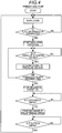
Fig. 4 is a flowchart illustrating an operation control of a primary side pump according to the embodiment. -
Fig. 5 is a graph illustrating operations of a primary side pump and a secondary side pump of the embodiment, and a detected value (P1) of the primary side pressure sensor and a detected value (P2) of the secondary side pressure sensor according to the operation. - A preferred embodiment of a liquid feeding apparatus according to the invention further includes: an acquisition frequency data holding unit which holds a relation between an acquisition frequency of acquiring signals from a primary side pressure sensor and a secondary side pressure sensor during a preloading operation and a length of a preloading time allocated to the preloading operation as acquisition frequency data; and an acquisition frequency determining unit which determines the acquisition frequency on the basis of the acquisition frequency data held in the acquisition frequency data holding unit, when the preloading time is determined by the preloading time determining unit. The preloading operation unit is configured to acquire signals from the primary side pressure sensor and the secondary side pressure sensor at the acquisition frequency determined by the acquisition frequency determining unit.
- A further preferred embodiment of the liquid feeding apparatus according to the invention further includes a preload determining unit which takes a difference between signals acquired from the primary side pressure sensor and the secondary side pressure sensor during the preloading operation and determines whether a difference value is within a preset predetermined range. The preloading operation unit is configured to complete the preloading operation when the difference value of the signals acquired from both sensors falls within a predetermined range.
- Hereinafter, an embodiment of a liquid feeding apparatus according to the invention will be described with reference to the drawings.
- First, the configuration of the liquid feeding apparatus will be described with reference to
Fig. 1 . - The liquid feeding apparatus of this embodiment includes a
primary side pump 2 and asecondary side pump 22. Theprimary side pump 2 and thesecondary side pump 22 are connected in series to each other. - The
primary side pump 2 includes apump head 3 having apump chamber 4 therein, and apump body 6. Thepump head 3 is provided at a distal end of thepump body 6. Thepump head 3 is provided with an inlet part which allows the liquid to flow into thepump chamber 4, and an outlet part which allows the liquid to flow out of thepump chamber 4. Acheck valve 16 for preventing backflow of the liquid is provided in the inlet part of thepump head 3. - The distal end of a
plunger 10 is slidably inserted into thepump chamber 4. A proximal end of theplunger 10 is held by acrosshead 8 housed in thepump body 6. Thecrosshead 8 moves inside thepump body 6 by the rotation of afeed screw 14 in one direction (a left-right direction in the drawing), and theplunger 10 moves in one direction accordingly. A primary sidepump driving motor 12 which rotates thefeed screw 14 is provided at the proximal end portion of thepump body 6. The primary sidepump driving motor 12 is a stepping motor. - The
secondary side pump 22 includes apump head 23 having apump chamber 24 therein, and apump body 28. Thepump head 23 is provided at the distal end of thepump body 28. Thepump head 23 is provided with an inlet part which allows the liquid to flow into thepump chamber 24, and an outlet part which allows the liquid to flow out of thepump chamber 24. Acheck valve 26 for preventing backflow of the liquid is provided in the inlet part of thepump head 23. - The distal end of a
plunger 32 is slidably inserted into thepump chamber 24. The proximal end of theplunger 32 is held by acrosshead 30 housed in thepump body 28. Thecrosshead 30 moves inside thepump body 28 by the rotation of afeed screw 36 in one direction (the left-right direction in the drawing), and theplunger 32 moves in one direction accordingly. A secondary sidepump driving motor 34 which rotates thefeed screw 36 is provided at the proximal end portion of thepump body 28. The secondary sidepump driving motor 34 is a stepping motor. - The inlet part of the
pump head 3 is connected to a container (not illustrated) that stores the liquid to be fed via a flow path. An inlet part of thepump head 23 is connected to an outlet part of thepump head 3 via a connectingflow path 18. A primaryside pressure sensor 20 for detecting the pressure (P1) in thepump chamber 4 is provided on the connectingflow path 18. - An
outlet flow path 38 is connected to the outlet part of thepump head 23. Theoutlet flow path 38 leads to, for example, an analysis flow path of a liquid chromatograph. A secondaryside pressure sensor 40 for detecting the pressure (P2) in thepump chamber 24 is provided on theoutlet flow path 38. - The operation of the primary side
pump driving motor 12 and the secondary sidepump driving motor 34 is controlled by acontrol unit 42. The detected signals obtained by the primaryside pressure sensor 20 and the secondaryside pressure sensor 40 are acquired into thecontrol unit 42. Thecontrol unit 42 controls the operation of the primary sidepump driving motor 12 on the basis of the signals from the primaryside pressure sensor 20 and the secondaryside pressure sensor 40 at the time of a preloading operation to be described later. - To briefly explain the operation of the liquid feeding apparatus, when the discharge operation of the liquid using the
primary side pump 2 is started, thecheck valve 16 is closed, thecheck valve 26 is opened, and the liquid from the outlet part of thepump head 3 is discharged to theoutlet flow path 38 through the connectingflow path 18, thecheck valve 26, and thepump chamber 24. At this time, thesecondary side pump 22 performs the suction operation at a flow rate smaller than the discharge flow rate of theprimary side pump 2, and a part of the liquid discharged from thepump head 3 is stored in thepump chamber 24. - When the discharge operation of the liquid using the
primary side pump 2 is terminated, the discharge operation of the liquid using thesecondary side pump 22 is started. When the discharge operation of the liquid using thesecondary side pump 22 is started, since the pressure inside thepump chamber 24 becomes higher than the pressure inside thepump chamber 4, thecheck valve 26 is closed. While the discharge operation of the liquid is being performed by thesecondary side pump 22, the suction operation and the preloading operation of the liquid are performed in theprimary side pump 2. When the discharge operation of the liquid using thesecondary side pump 22 is terminated, the discharge operation of the liquid using theprimary side pump 2 is started. - The preloading operation of the
primary side pump 2 is performed in order to prevent occurrence of defective liquid feeding when the liquid discharge operation of theprimary side pump 2 is started after the liquid discharge operation of thesecondary side pump 22 is terminated. That is, immediately after the suction operation of theprimary side pump 2 is terminated, the pressure inside thepump chamber 4 becomes lower than the pressure inside thepump chamber 24. Therefore, even when the suction and discharge operations of theprimary side pump 2 and thesecondary side pump 22 are switched immediately after the suction operation of theprimary side pump 2 is terminated, until the pressure inside thepump chamber 4 becomes equal to or higher than the pressure inside thepump chamber 24, the liquid is not fed from theprimary side pump 2, and the liquid feeding flow rate of the liquid feeding apparatus drops sharply, resulting in a defective liquid feeding. - Therefore, before the discharge operation of the
secondary side pump 22 is terminated, theprimary side pump 2 executes a preloading operation for keeping the pressure inside thepump chamber 4 at the same pressure as the pressure inside thepump chamber 24. In the preloading operation, thecontrol unit 42 acquires a signal from the primaryside pressure sensor 20 and a signal from the secondaryside pressure sensor 40, and performs discharge and driving, while performing the feedback control of theprimary side pump 2 so that the pressure inside thepump chamber 4 becomes equal to the pressure inside thepump chamber 24. - The configuration of the
control unit 42 will be described in more detail with reference toFig. 2 . - The
control unit 42 is achieved by a dedicated computer provided in the apparatus or a general-purpose personal computer. Thecontrol unit 42 includes a flowrate setting unit 44, adrive control unit 46, apreloading operation unit 47, a preloadingtime determining unit 48, an acquisitionfrequency determining unit 50, an acquisition frequencydata holding unit 52, asignal acquisition unit 54, and apreload determining unit 56. The flowrate setting unit 44, thedrive control unit 46, thepreloading operation unit 47, the preloadingtime determining unit 48, the acquisitionfrequency determining unit 50, thesignal acquisition unit 54, and thepreload determining unit 56 are functions obtained by executing a program stored in the storage device provided in thecontrol unit 42. The acquisition frequencydata holding unit 52 is a function achieved by a partial region of the storage device provided in thecontrol unit 42. - The flow
rate setting unit 44 sets the liquid feeding flow rate of the liquid feeding apparatus on the basis of the information which is input by the user. - The
drive control unit 46 controls the operations of the primary sidepump driving motor 12 and the secondary sidepump driving motor 34 so that the flow rate of the liquid fed through theoutlet flow path 38 becomes a set value of the liquid feeding flow rate which is set by the flowrate setting unit 44. - The
preloading operation unit 47 causes theprimary side pump 2 to execute the preloading operation during the discharge operation of thesecondary side pump 22. The preloading operation is executed within the preloading time determined by a preloadingtime determining unit 48 to be described later. The preloading operation refers to an operation of increasing the pressure inside thepump chamber 4, by moving theplunger 10 of theprimary side pump 2 after the suction operation in the discharge direction. - When the liquid feeding flow rate is set by the flow
rate setting unit 44, the preloadingtime determining unit 48 determines the time which is assigned to the preloading operation, on the basis of the set value. The driving speed of thesecondary side pump 22 is determined by the set value of the liquid feeding flow rate. Therefore, when the liquid feeding flow rate increases, the driving speed of thesecondary side pump 22 becomes faster accordingly, and the time required for the discharge operation of thesecondary side pump 22 becomes shorter. - During the discharge operation of the
secondary side pump 22, theprimary side pump 2 executes the suction operation and the preloading operation. In this embodiment, since theprimary side pump 2 performs the suction operation at the maximum driving speed, the time required for the suction operation of theprimary side pump 2 is constant. Therefore, the time (preloading time) allocated to the preloading operation of theprimary side pump 2 is the time obtained by subtracting the time (constant) required for the suction operation of the primary side pump 2 from the time required for the discharge operation of thesecondary side pump 22. - On the basis of the preloading time determined by the preloading
time determining unit 48 and the acquisition frequency data acquired in advance, the acquisitionfrequency determining unit 50 determines the acquisition frequency (acquisition speed) of the signal from the primaryside pressure sensor 20 and the secondaryside pressure sensor 40 during the preloading time. The acquisition frequency data is held in the acquisition frequencydata holding unit 52. - The acquisition frequency data is set such that the acquisition frequency is low as the preloading time is long and the acquisition frequency is high as the preloading time is short. Acquisition frequency data was created on the basis of data obtained by experiments. Specifically, the acquisition frequency data is created so that an acquisition frequency is an acquisition frequency in which a noise value is always equal to or less than a predetermined allowable value, and in which the signal is acquired at a time interval shorter than the time required for the motor of the primary side pump to rotate by a minimum rotation angle. The allowable value of noise is, for example, the maximum value in a predetermined range compared with the difference value between the primary
side pressure sensor 20 and the secondaryside pressure sensor 40 in a preloading determination to be described later. The time required for the minimum rotation angle of the motor of the primary side pump is obtained from a maximum preloading required volume and the preloading time estimated by the compression rate or the compression volume of the compressed solvent, and the liquid feed pressure. - At the time of the preloading operation of the
primary side pump 2, thesignal acquisition unit 54 acquires signals of the primaryside pressure sensor 20 and the secondaryside pressure sensor 40 with the acquisition frequency determined by the acquisitionfrequency determining unit 50. - The
preload determining unit 56 takes the difference between the signals of the primaryside pressure sensor 20 and the secondaryside pressure sensor 40 acquired by thesignal acquisition unit 54, and determines whether the difference value is within a predetermined range. The predetermined range is, for example, 0 to 0.05 MPa. When thepreload determining unit 56 determines that the difference value between the signals of the primaryside pressure sensor 20 and the secondaryside pressure sensor 40 is within the predetermined range, thepreloading operation unit 47 terminates the preloading operation. - Next, the initial setting operation of the liquid feeding apparatus will be described with reference to the flowchart of
Fig. 3 . - In the initial setting, first, a flow rate to be fed through the
outlet flow path 38 is set on the basis of input information from the user. When the liquid feeding flow rate is set, the preloading time assigned to the preloading operation of theprimary side pump 2 is determined on the basis of the flow rate. When the preloading time is determined, the driving speed (preloading speed) of the primaryside pump motor 12 for completing the preloading operation within the preloading time is determined. When the preloading speed is determined, the acquisition frequency of the signals from the primaryside pressure sensor 20 and the secondaryside pressure sensor 40 is determined on the basis of the preloading speed. - Next, the operation of the primary side pump during liquid feeding will be described with reference to
Figs. 4 and5 . InFig. 5 , an upper graph illustrates a time change in the plunger speed of the primary side pump (thick line) and the secondary side pump (thin line), and a lower graph illustrates a time change of the detected pressure P1 of the primaryside pressure sensor 20 and the detected pressure P2 of the secondaryside pressure sensor 40. - The
secondary side pump 22 repeatedly executes the suction operation and the discharge operation at a constant speed corresponding to the set liquid feeding flow rate. When the secondary side pump 22 starts the discharge operation, the primary side pump 2 starts the suction operation of the liquid. This suction operation is performed by driving theplunger 10 to the suction side at the maximum possible design speed. - After the suction operation of the
primary side pump 2 is terminated, the preloading operation is started. First, the discharge operation of theprimary side pump 2 is started. Specifically, theplunger 10 is driven to the discharge side (the right side inFig. 1 ) at a speed (preloading speed) which is set on the basis of the time (preloading time) assigned to the preloading operation. After the discharge operation is started, the signals from the primaryside pressure sensor 20 and the secondaryside pressure sensor 40 are acquired with a preset acquisition frequency, and the difference between the signal intensities is taken each time. The discharge operation is continued until the difference value falls within a preset predetermined range, and when the difference value falls within the predetermined range, the discharge operation is terminated. As a result, the pressure (P1) inside thepump chamber 4 of theprimary side pump 2 and the pressure (P2) inside thepump chamber 24 of thesecondary side pump 22 become substantially the same. - After completion of the preloading operation, when there is a discharge timing of the
primary side pump 2, that is, timing of switching between the suction and discharge operations of theprimary side pump 2 and thesecondary side pump 22 is obtained, theplunger 10 is driven to the discharge side at a predetermined speed depending on the set flow rate to perform the liquid feeding. In thesecondary side pump 22, the suction operation is performed at a flow rate smaller than that of theprimary side pump 2, and a part of the liquid discharged from theprimary side pump 2 is stored in thepump chamber 24. Further, the flow rate corresponding to the value obtained by subtracting the suction flow rate of the secondary side pump 22 from the discharge flow rate from theprimary side pump 2 becomes the flow rate of the liquid feeding performed through theoutlet flow path 38. -
- 2... primary side pump
- 3, 2 3... pump head
- 4, 2 4... pump chamber
- 6, 2 8... pump body
- 8, 30... crosshead
- 10, 32... plunger
- 12, 34... motor
- 14, 36... feed screw
- 16, 2 6... check valve
- 20, 40... pressure sensor
- 42... control unit
- 44... flow rate setting unit
- 46... drive control unit
- 47... preloading operation unit
- 48... preloading time determining unit
- 50... acquisition frequency determining unit
- 52... acquisition frequency data holding unit
- 54... signal acquisition unit
- 56... preload determining unit
Claims (3)
- A liquid feeding apparatus comprising:a pump unit which has a primary side pump and a secondary side pump configured to perform suction and discharge of liquid by driving a distal end of a plunger in one direction in a pump chamber, an outlet part of the primary side pump and an inlet part of the secondary side pump being connected to each other via a check valve;a temporary side pump pressure sensor which detects the pressure inside the pump chamber of the primary side pump;a secondary side pressure sensor which detects the pressure inside the pump chamber of the secondary side pump;a drive control unit which controls operation of the primary side pump and the secondary side pump to perform a suction operation of the secondary side pump during the discharge operation of the primary side pump and to perform a suction operation of the primary side pump during the discharge operation of the secondary side pump;a preloading operation unit which acquires a signal of the primary side pressure sensor and a signal of the secondary side pressure sensor after the suction operation of the primary side pump is terminated and before the discharge operation of the secondary side pump is terminated, and executes a preloading operation of driving the primary side pump to the discharge side, until the pressure inside the pump chamber of the primary side pump becomes substantially equal to the pressure inside the pump chamber of the secondary side pump, on the basis of an acquired signal; anda preloading time determining unit which determines a time allocated to the preloading operation, on the basis of a preset liquid feeding flow rate,wherein the preloading operation unit is configured to acquire the signal from the primary side pressure sensor and the secondary side pressure sensor at an acquisition frequency determined depending on the preloading time determined by the preloading time determining unit.
- The liquid feeding apparatus according to claim 1, further comprising:an acquisition frequency data holding unit which holds a relation between an acquisition frequency of acquiring signals from the primary side pressure sensor and the secondary side pressure sensor during the preloading operation and a length of a preloading time allocated to the preloading operation, as acquisition frequency data; andan acquisition frequency determining unit which determines the acquisition frequency on the basis of the acquisition frequency data held in the acquisition frequency data holding unit, when the preloading time is determined by the preloading time determining unit,wherein the preloading operation unit is configured to acquire signals from the primary side pressure sensor and the secondary side pressure sensor at the acquisition frequency determined by the acquisition frequency determining unit.
- The liquid feeding apparatus according to claim 1 or 2, further comprising:a preload determining unit which takes a difference between signals acquired from the primary side pressure sensor and the secondary side pressure sensor during the preloading operation and determines whether a difference value is within a preset predetermined range,wherein the preloading operation unit completes the preloading operation when the difference value of the signals acquired from both sensors falls within a predetermined range.
Applications Claiming Priority (1)
| Application Number | Priority Date | Filing Date | Title |
|---|---|---|---|
| PCT/JP2015/083705 WO2017094097A1 (en) | 2015-12-01 | 2015-12-01 | Liquid delivery device |
Publications (3)
| Publication Number | Publication Date |
|---|---|
| EP3333421A1 true EP3333421A1 (en) | 2018-06-13 |
| EP3333421A4 EP3333421A4 (en) | 2019-01-16 |
| EP3333421B1 EP3333421B1 (en) | 2019-11-13 |
Family
ID=58796577
Family Applications (1)
| Application Number | Title | Priority Date | Filing Date |
|---|---|---|---|
| EP15909727.8A Active EP3333421B1 (en) | 2015-12-01 | 2015-12-01 | Liquid feeding apparatus |
Country Status (5)
| Country | Link |
|---|---|
| US (1) | US10514028B2 (en) |
| EP (1) | EP3333421B1 (en) |
| JP (1) | JP6439881B2 (en) |
| CN (1) | CN108026908B (en) |
| WO (1) | WO2017094097A1 (en) |
Families Citing this family (5)
| Publication number | Priority date | Publication date | Assignee | Title |
|---|---|---|---|---|
| US20180306179A1 (en) * | 2017-04-24 | 2018-10-25 | Wanner Engineering, Inc. | Zero pulsation pump |
| CN110621878B (en) * | 2017-07-03 | 2021-03-30 | 株式会社岛津制作所 | Liquid feeding device |
| WO2019021475A1 (en) | 2017-07-28 | 2019-01-31 | 株式会社島津製作所 | Liquid feeding device |
| US11307179B2 (en) * | 2017-10-23 | 2022-04-19 | Shimadzu Corporation | Liquid feeding device and fluid chromatograph |
| WO2019130625A1 (en) * | 2017-12-25 | 2019-07-04 | 株式会社島津製作所 | Liquid feeding device |
Family Cites Families (20)
| Publication number | Priority date | Publication date | Assignee | Title |
|---|---|---|---|---|
| US4352636A (en) | 1980-04-14 | 1982-10-05 | Spectra-Physics, Inc. | Dual piston pump |
| JPS61178582A (en) * | 1985-02-01 | 1986-08-11 | Jeol Ltd | Liquid feeding pump apparatus |
| US4681513A (en) | 1985-02-01 | 1987-07-21 | Jeol Ltd. | Two-stage pump assembly |
| JPH0823553B2 (en) * | 1988-06-27 | 1996-03-06 | 横河電機株式会社 | Liquid transfer device |
| JP3491948B2 (en) | 1993-03-05 | 2004-02-03 | ウォーターズ・インベストメンツ・リミテッド | Solvent pump feeder |
| US6106238A (en) * | 1998-10-02 | 2000-08-22 | Water Investments Limited | Bubble detection and recovery in a liquid pumping system |
| US6712587B2 (en) * | 2001-12-21 | 2004-03-30 | Waters Investments Limited | Hydraulic amplifier pump for use in ultrahigh pressure liquid chromatography |
| US7163379B2 (en) * | 2002-03-18 | 2007-01-16 | Hitachi High-Technologies Corporation | Gradient liquid feed pump system, and liquid chromatograph |
| JP4276827B2 (en) * | 2002-10-18 | 2009-06-10 | 株式会社日立ハイテクノロジーズ | Liquid chromatograph pump and operation method thereof |
| JP2004150402A (en) * | 2002-11-01 | 2004-05-27 | Hitachi High-Technologies Corp | Pump for liquid chromatography |
| JP4206308B2 (en) * | 2003-08-01 | 2009-01-07 | 株式会社日立ハイテクノロジーズ | Liquid chromatograph pump |
| JP4377639B2 (en) * | 2003-09-18 | 2009-12-02 | 株式会社日立ハイテクノロジーズ | Pumps and liquid pumps for chromatography |
| JP4377761B2 (en) * | 2004-07-01 | 2009-12-02 | 株式会社日立ハイテクノロジーズ | Liquid chromatograph |
| JP4887295B2 (en) * | 2004-08-24 | 2012-02-29 | ウオーターズ・テクノロジーズ・コーポレイシヨン | Apparatus, system, and method for pump and injector synchronization to compensate flow |
| JP4709629B2 (en) * | 2005-10-19 | 2011-06-22 | 株式会社日立ハイテクノロジーズ | Pump device |
| JP5049808B2 (en) * | 2008-01-31 | 2012-10-17 | 株式会社日立ハイテクノロジーズ | Liquid feeding device and analyzer having the same |
| JP5624825B2 (en) * | 2010-07-29 | 2014-11-12 | 株式会社日立ハイテクノロジーズ | Liquid chromatograph pump and liquid chromatograph |
| JP2012031817A (en) * | 2010-08-02 | 2012-02-16 | Shimadzu Corp | Liquid feed pump and liquid feed device |
| CN203978789U (en) * | 2014-07-02 | 2014-12-03 | 北汽福田汽车股份有限公司 | A kind of reversing arrangement and pump truck based on pressure signal |
| WO2017090148A1 (en) * | 2015-11-26 | 2017-06-01 | 株式会社島津製作所 | Liquid feed device, liquid feed control method for liquid feed device, and liquid feed control program for liquid feed device |
-
2015
- 2015-12-01 JP JP2017553515A patent/JP6439881B2/en active Active
- 2015-12-01 CN CN201580082892.7A patent/CN108026908B/en active Active
- 2015-12-01 US US15/756,746 patent/US10514028B2/en active Active
- 2015-12-01 EP EP15909727.8A patent/EP3333421B1/en active Active
- 2015-12-01 WO PCT/JP2015/083705 patent/WO2017094097A1/en active Application Filing
Also Published As
| Publication number | Publication date |
|---|---|
| CN108026908B (en) | 2019-06-28 |
| JPWO2017094097A1 (en) | 2018-05-17 |
| US10514028B2 (en) | 2019-12-24 |
| EP3333421B1 (en) | 2019-11-13 |
| WO2017094097A1 (en) | 2017-06-08 |
| CN108026908A (en) | 2018-05-11 |
| US20180245581A1 (en) | 2018-08-30 |
| EP3333421A4 (en) | 2019-01-16 |
| JP6439881B2 (en) | 2018-12-19 |
Similar Documents
| Publication | Publication Date | Title |
|---|---|---|
| US10514028B2 (en) | Liquid delivery device | |
| US11307179B2 (en) | Liquid feeding device and fluid chromatograph | |
| JP3709409B2 (en) | Gradient pump system and liquid chromatograph | |
| JP6780780B2 (en) | Liquid feeder | |
| EP3660310B1 (en) | Liquid feeding device | |
| JP4511578B2 (en) | Liquid feeding device, liquid chromatograph, and method of operating liquid feeding device | |
| WO2005046768B1 (en) | Syringe pump rapid occlusion detection system | |
| JP7123968B2 (en) | A positive displacement pump for medical fluids and a blood processing apparatus comprising a positive displacement pump for medical fluids and a method for controlling a positive displacement pump for medical fluids | |
| JP2009180617A (en) | Solvent delivery device and analytical system having the same | |
| JP2014215125A (en) | High pressure constant flow rate pump and method for feeding liquid of high pressure constant flow rate | |
| CN114026326B (en) | Diaphragm pump and blood purifying device using the same | |
| CN107893793B (en) | Cylinder operation condition monitoring device | |
| JP5672133B2 (en) | Flow measuring device | |
| CN110621993A (en) | Automatic sampler and fluid chromatograph | |
| US20220128533A1 (en) | Liquid sending system for liquid chromatograph | |
| JP2012031817A (en) | Liquid feed pump and liquid feed device | |
| JP2016205944A (en) | Auto sampler | |
| WO2021245767A1 (en) | Liquid feed device | |
| CN113544504B (en) | Analysis system of liquid chromatograph | |
| US20230384271A1 (en) | Liquid Feeding Pump and Liquid Feeding Method | |
| JP2008019823A (en) | Control method of liquid constant feeder | |
| CN112005111A (en) | Chromatographic analysis system |
Legal Events
| Date | Code | Title | Description |
|---|---|---|---|
| STAA | Information on the status of an ep patent application or granted ep patent |
Free format text: STATUS: THE INTERNATIONAL PUBLICATION HAS BEEN MADE |
|
| PUAI | Public reference made under article 153(3) epc to a published international application that has entered the european phase |
Free format text: ORIGINAL CODE: 0009012 |
|
| STAA | Information on the status of an ep patent application or granted ep patent |
Free format text: STATUS: REQUEST FOR EXAMINATION WAS MADE |
|
| 17P | Request for examination filed |
Effective date: 20180309 |
|
| AK | Designated contracting states |
Kind code of ref document: A1 Designated state(s): AL AT BE BG CH CY CZ DE DK EE ES FI FR GB GR HR HU IE IS IT LI LT LU LV MC MK MT NL NO PL PT RO RS SE SI SK SM TR |
|
| AX | Request for extension of the european patent |
Extension state: BA ME |
|
| REG | Reference to a national code |
Ref country code: DE Ref legal event code: R079 Ref document number: 602015041867 Country of ref document: DE Free format text: PREVIOUS MAIN CLASS: F04B0013000000 Ipc: F04B0001020000 |
|
| A4 | Supplementary search report drawn up and despatched |
Effective date: 20181213 |
|
| RIC1 | Information provided on ipc code assigned before grant |
Ipc: F04B 1/02 20060101AFI20181207BHEP Ipc: G01N 30/36 20060101ALI20181207BHEP Ipc: F04B 11/00 20060101ALI20181207BHEP Ipc: B01D 15/14 20060101ALI20181207BHEP Ipc: F04B 49/06 20060101ALI20181207BHEP Ipc: F04B 13/00 20060101ALI20181207BHEP Ipc: F04B 23/06 20060101ALI20181207BHEP |
|
| DAV | Request for validation of the european patent (deleted) | ||
| DAX | Request for extension of the european patent (deleted) | ||
| GRAP | Despatch of communication of intention to grant a patent |
Free format text: ORIGINAL CODE: EPIDOSNIGR1 |
|
| STAA | Information on the status of an ep patent application or granted ep patent |
Free format text: STATUS: GRANT OF PATENT IS INTENDED |
|
| INTG | Intention to grant announced |
Effective date: 20190619 |
|
| GRAS | Grant fee paid |
Free format text: ORIGINAL CODE: EPIDOSNIGR3 |
|
| GRAA | (expected) grant |
Free format text: ORIGINAL CODE: 0009210 |
|
| STAA | Information on the status of an ep patent application or granted ep patent |
Free format text: STATUS: THE PATENT HAS BEEN GRANTED |
|
| AK | Designated contracting states |
Kind code of ref document: B1 Designated state(s): AL AT BE BG CH CY CZ DE DK EE ES FI FR GB GR HR HU IE IS IT LI LT LU LV MC MK MT NL NO PL PT RO RS SE SI SK SM TR |
|
| REG | Reference to a national code |
Ref country code: CH Ref legal event code: EP Ref country code: AT Ref legal event code: REF Ref document number: 1201923 Country of ref document: AT Kind code of ref document: T Effective date: 20191115 |
|
| REG | Reference to a national code |
Ref country code: DE Ref legal event code: R096 Ref document number: 602015041867 Country of ref document: DE |
|
| REG | Reference to a national code |
Ref country code: IE Ref legal event code: FG4D |
|
| REG | Reference to a national code |
Ref country code: NL Ref legal event code: MP Effective date: 20191113 |
|
| REG | Reference to a national code |
Ref country code: LT Ref legal event code: MG4D |
|
| PG25 | Lapsed in a contracting state [announced via postgrant information from national office to epo] |
Ref country code: SE Free format text: LAPSE BECAUSE OF FAILURE TO SUBMIT A TRANSLATION OF THE DESCRIPTION OR TO PAY THE FEE WITHIN THE PRESCRIBED TIME-LIMIT Effective date: 20191113 Ref country code: PL Free format text: LAPSE BECAUSE OF FAILURE TO SUBMIT A TRANSLATION OF THE DESCRIPTION OR TO PAY THE FEE WITHIN THE PRESCRIBED TIME-LIMIT Effective date: 20191113 Ref country code: NO Free format text: LAPSE BECAUSE OF FAILURE TO SUBMIT A TRANSLATION OF THE DESCRIPTION OR TO PAY THE FEE WITHIN THE PRESCRIBED TIME-LIMIT Effective date: 20200213 Ref country code: PT Free format text: LAPSE BECAUSE OF FAILURE TO SUBMIT A TRANSLATION OF THE DESCRIPTION OR TO PAY THE FEE WITHIN THE PRESCRIBED TIME-LIMIT Effective date: 20200313 Ref country code: BG Free format text: LAPSE BECAUSE OF FAILURE TO SUBMIT A TRANSLATION OF THE DESCRIPTION OR TO PAY THE FEE WITHIN THE PRESCRIBED TIME-LIMIT Effective date: 20200213 Ref country code: NL Free format text: LAPSE BECAUSE OF FAILURE TO SUBMIT A TRANSLATION OF THE DESCRIPTION OR TO PAY THE FEE WITHIN THE PRESCRIBED TIME-LIMIT Effective date: 20191113 Ref country code: LV Free format text: LAPSE BECAUSE OF FAILURE TO SUBMIT A TRANSLATION OF THE DESCRIPTION OR TO PAY THE FEE WITHIN THE PRESCRIBED TIME-LIMIT Effective date: 20191113 Ref country code: FI Free format text: LAPSE BECAUSE OF FAILURE TO SUBMIT A TRANSLATION OF THE DESCRIPTION OR TO PAY THE FEE WITHIN THE PRESCRIBED TIME-LIMIT Effective date: 20191113 Ref country code: GR Free format text: LAPSE BECAUSE OF FAILURE TO SUBMIT A TRANSLATION OF THE DESCRIPTION OR TO PAY THE FEE WITHIN THE PRESCRIBED TIME-LIMIT Effective date: 20200214 Ref country code: LT Free format text: LAPSE BECAUSE OF FAILURE TO SUBMIT A TRANSLATION OF THE DESCRIPTION OR TO PAY THE FEE WITHIN THE PRESCRIBED TIME-LIMIT Effective date: 20191113 |
|
| PG25 | Lapsed in a contracting state [announced via postgrant information from national office to epo] |
Ref country code: HR Free format text: LAPSE BECAUSE OF FAILURE TO SUBMIT A TRANSLATION OF THE DESCRIPTION OR TO PAY THE FEE WITHIN THE PRESCRIBED TIME-LIMIT Effective date: 20191113 Ref country code: IS Free format text: LAPSE BECAUSE OF FAILURE TO SUBMIT A TRANSLATION OF THE DESCRIPTION OR TO PAY THE FEE WITHIN THE PRESCRIBED TIME-LIMIT Effective date: 20200313 Ref country code: RS Free format text: LAPSE BECAUSE OF FAILURE TO SUBMIT A TRANSLATION OF THE DESCRIPTION OR TO PAY THE FEE WITHIN THE PRESCRIBED TIME-LIMIT Effective date: 20191113 |
|
| PG25 | Lapsed in a contracting state [announced via postgrant information from national office to epo] |
Ref country code: AL Free format text: LAPSE BECAUSE OF FAILURE TO SUBMIT A TRANSLATION OF THE DESCRIPTION OR TO PAY THE FEE WITHIN THE PRESCRIBED TIME-LIMIT Effective date: 20191113 |
|
| PG25 | Lapsed in a contracting state [announced via postgrant information from national office to epo] |
Ref country code: CZ Free format text: LAPSE BECAUSE OF FAILURE TO SUBMIT A TRANSLATION OF THE DESCRIPTION OR TO PAY THE FEE WITHIN THE PRESCRIBED TIME-LIMIT Effective date: 20191113 Ref country code: ES Free format text: LAPSE BECAUSE OF FAILURE TO SUBMIT A TRANSLATION OF THE DESCRIPTION OR TO PAY THE FEE WITHIN THE PRESCRIBED TIME-LIMIT Effective date: 20191113 Ref country code: RO Free format text: LAPSE BECAUSE OF FAILURE TO SUBMIT A TRANSLATION OF THE DESCRIPTION OR TO PAY THE FEE WITHIN THE PRESCRIBED TIME-LIMIT Effective date: 20191113 Ref country code: EE Free format text: LAPSE BECAUSE OF FAILURE TO SUBMIT A TRANSLATION OF THE DESCRIPTION OR TO PAY THE FEE WITHIN THE PRESCRIBED TIME-LIMIT Effective date: 20191113 Ref country code: DK Free format text: LAPSE BECAUSE OF FAILURE TO SUBMIT A TRANSLATION OF THE DESCRIPTION OR TO PAY THE FEE WITHIN THE PRESCRIBED TIME-LIMIT Effective date: 20191113 |
|
| REG | Reference to a national code |
Ref country code: CH Ref legal event code: PL |
|
| REG | Reference to a national code |
Ref country code: DE Ref legal event code: R097 Ref document number: 602015041867 Country of ref document: DE |
|
| REG | Reference to a national code |
Ref country code: AT Ref legal event code: MK05 Ref document number: 1201923 Country of ref document: AT Kind code of ref document: T Effective date: 20191113 |
|
| REG | Reference to a national code |
Ref country code: BE Ref legal event code: MM Effective date: 20191231 |
|
| PG25 | Lapsed in a contracting state [announced via postgrant information from national office to epo] |
Ref country code: SM Free format text: LAPSE BECAUSE OF FAILURE TO SUBMIT A TRANSLATION OF THE DESCRIPTION OR TO PAY THE FEE WITHIN THE PRESCRIBED TIME-LIMIT Effective date: 20191113 Ref country code: MC Free format text: LAPSE BECAUSE OF FAILURE TO SUBMIT A TRANSLATION OF THE DESCRIPTION OR TO PAY THE FEE WITHIN THE PRESCRIBED TIME-LIMIT Effective date: 20191113 Ref country code: SK Free format text: LAPSE BECAUSE OF FAILURE TO SUBMIT A TRANSLATION OF THE DESCRIPTION OR TO PAY THE FEE WITHIN THE PRESCRIBED TIME-LIMIT Effective date: 20191113 |
|
| PLBE | No opposition filed within time limit |
Free format text: ORIGINAL CODE: 0009261 |
|
| STAA | Information on the status of an ep patent application or granted ep patent |
Free format text: STATUS: NO OPPOSITION FILED WITHIN TIME LIMIT |
|
| 26N | No opposition filed |
Effective date: 20200814 |
|
| PG25 | Lapsed in a contracting state [announced via postgrant information from national office to epo] |
Ref country code: IE Free format text: LAPSE BECAUSE OF NON-PAYMENT OF DUE FEES Effective date: 20191201 Ref country code: LU Free format text: LAPSE BECAUSE OF NON-PAYMENT OF DUE FEES Effective date: 20191201 |
|
| PG25 | Lapsed in a contracting state [announced via postgrant information from national office to epo] |
Ref country code: CH Free format text: LAPSE BECAUSE OF NON-PAYMENT OF DUE FEES Effective date: 20191231 Ref country code: LI Free format text: LAPSE BECAUSE OF NON-PAYMENT OF DUE FEES Effective date: 20191231 Ref country code: AT Free format text: LAPSE BECAUSE OF FAILURE TO SUBMIT A TRANSLATION OF THE DESCRIPTION OR TO PAY THE FEE WITHIN THE PRESCRIBED TIME-LIMIT Effective date: 20191113 Ref country code: BE Free format text: LAPSE BECAUSE OF NON-PAYMENT OF DUE FEES Effective date: 20191231 Ref country code: SI Free format text: LAPSE BECAUSE OF FAILURE TO SUBMIT A TRANSLATION OF THE DESCRIPTION OR TO PAY THE FEE WITHIN THE PRESCRIBED TIME-LIMIT Effective date: 20191113 |
|
| PG25 | Lapsed in a contracting state [announced via postgrant information from national office to epo] |
Ref country code: IT Free format text: LAPSE BECAUSE OF FAILURE TO SUBMIT A TRANSLATION OF THE DESCRIPTION OR TO PAY THE FEE WITHIN THE PRESCRIBED TIME-LIMIT Effective date: 20191113 |
|
| PG25 | Lapsed in a contracting state [announced via postgrant information from national office to epo] |
Ref country code: CY Free format text: LAPSE BECAUSE OF FAILURE TO SUBMIT A TRANSLATION OF THE DESCRIPTION OR TO PAY THE FEE WITHIN THE PRESCRIBED TIME-LIMIT Effective date: 20191113 |
|
| PG25 | Lapsed in a contracting state [announced via postgrant information from national office to epo] |
Ref country code: HU Free format text: LAPSE BECAUSE OF FAILURE TO SUBMIT A TRANSLATION OF THE DESCRIPTION OR TO PAY THE FEE WITHIN THE PRESCRIBED TIME-LIMIT; INVALID AB INITIO Effective date: 20151201 Ref country code: MT Free format text: LAPSE BECAUSE OF FAILURE TO SUBMIT A TRANSLATION OF THE DESCRIPTION OR TO PAY THE FEE WITHIN THE PRESCRIBED TIME-LIMIT Effective date: 20191113 |
|
| PG25 | Lapsed in a contracting state [announced via postgrant information from national office to epo] |
Ref country code: TR Free format text: LAPSE BECAUSE OF FAILURE TO SUBMIT A TRANSLATION OF THE DESCRIPTION OR TO PAY THE FEE WITHIN THE PRESCRIBED TIME-LIMIT Effective date: 20191113 |
|
| PG25 | Lapsed in a contracting state [announced via postgrant information from national office to epo] |
Ref country code: MK Free format text: LAPSE BECAUSE OF FAILURE TO SUBMIT A TRANSLATION OF THE DESCRIPTION OR TO PAY THE FEE WITHIN THE PRESCRIBED TIME-LIMIT Effective date: 20191113 |
|
| PGFP | Annual fee paid to national office [announced via postgrant information from national office to epo] |
Ref country code: GB Payment date: 20231102 Year of fee payment: 9 |
|
| PGFP | Annual fee paid to national office [announced via postgrant information from national office to epo] |
Ref country code: FR Payment date: 20231108 Year of fee payment: 9 Ref country code: DE Payment date: 20231031 Year of fee payment: 9 |