EP3333404A1 - Elektropneumatisches luftführungssystem einer klimatisierung sowie verfahren - Google Patents
Elektropneumatisches luftführungssystem einer klimatisierung sowie verfahren Download PDFInfo
- Publication number
- EP3333404A1 EP3333404A1 EP17206288.7A EP17206288A EP3333404A1 EP 3333404 A1 EP3333404 A1 EP 3333404A1 EP 17206288 A EP17206288 A EP 17206288A EP 3333404 A1 EP3333404 A1 EP 3333404A1
- Authority
- EP
- European Patent Office
- Prior art keywords
- air
- compressor
- ecs
- bleed
- auxiliary
- Prior art date
- Legal status (The legal status is an assumption and is not a legal conclusion. Google has not performed a legal analysis and makes no representation as to the accuracy of the status listed.)
- Granted
Links
Images

Classifications
-
- B—PERFORMING OPERATIONS; TRANSPORTING
- B64—AIRCRAFT; AVIATION; COSMONAUTICS
- B64D—EQUIPMENT FOR FITTING IN OR TO AIRCRAFT; FLIGHT SUITS; PARACHUTES; ARRANGEMENT OR MOUNTING OF POWER PLANTS OR PROPULSION TRANSMISSIONS IN AIRCRAFT
- B64D13/00—Arrangements or adaptations of air-treatment apparatus for aircraft crew or passengers, or freight space
- B64D13/06—Arrangements or adaptations of air-treatment apparatus for aircraft crew or passengers, or freight space the air being conditioned
- B64D13/08—Arrangements or adaptations of air-treatment apparatus for aircraft crew or passengers, or freight space the air being conditioned the air being heated or cooled
-
- B—PERFORMING OPERATIONS; TRANSPORTING
- B64—AIRCRAFT; AVIATION; COSMONAUTICS
- B64D—EQUIPMENT FOR FITTING IN OR TO AIRCRAFT; FLIGHT SUITS; PARACHUTES; ARRANGEMENT OR MOUNTING OF POWER PLANTS OR PROPULSION TRANSMISSIONS IN AIRCRAFT
- B64D27/00—Arrangement or mounting of power plants in aircraft; Aircraft characterised by the type or position of power plants
- B64D27/02—Aircraft characterised by the type or position of power plants
- B64D27/10—Aircraft characterised by the type or position of power plants of gas-turbine type
-
- F—MECHANICAL ENGINEERING; LIGHTING; HEATING; WEAPONS; BLASTING
- F01—MACHINES OR ENGINES IN GENERAL; ENGINE PLANTS IN GENERAL; STEAM ENGINES
- F01D—NON-POSITIVE DISPLACEMENT MACHINES OR ENGINES, e.g. STEAM TURBINES
- F01D15/00—Adaptations of machines or engines for special use; Combinations of engines with devices driven thereby
- F01D15/10—Adaptations for driving, or combinations with, electric generators
-
- F—MECHANICAL ENGINEERING; LIGHTING; HEATING; WEAPONS; BLASTING
- F02—COMBUSTION ENGINES; HOT-GAS OR COMBUSTION-PRODUCT ENGINE PLANTS
- F02C—GAS-TURBINE PLANTS; AIR INTAKES FOR JET-PROPULSION PLANTS; CONTROLLING FUEL SUPPLY IN AIR-BREATHING JET-PROPULSION PLANTS
- F02C3/00—Gas-turbine plants characterised by the use of combustion products as the working fluid
- F02C3/04—Gas-turbine plants characterised by the use of combustion products as the working fluid having a turbine driving a compressor
-
- F—MECHANICAL ENGINEERING; LIGHTING; HEATING; WEAPONS; BLASTING
- F02—COMBUSTION ENGINES; HOT-GAS OR COMBUSTION-PRODUCT ENGINE PLANTS
- F02C—GAS-TURBINE PLANTS; AIR INTAKES FOR JET-PROPULSION PLANTS; CONTROLLING FUEL SUPPLY IN AIR-BREATHING JET-PROPULSION PLANTS
- F02C6/00—Plural gas-turbine plants; Combinations of gas-turbine plants with other apparatus; Adaptations of gas-turbine plants for special use
- F02C6/04—Gas-turbine plants providing heated or pressurised working fluid for other apparatus, e.g. without mechanical power output
- F02C6/06—Gas-turbine plants providing heated or pressurised working fluid for other apparatus, e.g. without mechanical power output providing compressed gas
- F02C6/08—Gas-turbine plants providing heated or pressurised working fluid for other apparatus, e.g. without mechanical power output providing compressed gas the gas being bled from the gas-turbine compressor
-
- F—MECHANICAL ENGINEERING; LIGHTING; HEATING; WEAPONS; BLASTING
- F02—COMBUSTION ENGINES; HOT-GAS OR COMBUSTION-PRODUCT ENGINE PLANTS
- F02C—GAS-TURBINE PLANTS; AIR INTAKES FOR JET-PROPULSION PLANTS; CONTROLLING FUEL SUPPLY IN AIR-BREATHING JET-PROPULSION PLANTS
- F02C7/00—Features, components parts, details or accessories, not provided for in, or of interest apart form groups F02C1/00 - F02C6/00; Air intakes for jet-propulsion plants
- F02C7/12—Cooling of plants
- F02C7/16—Cooling of plants characterised by cooling medium
- F02C7/18—Cooling of plants characterised by cooling medium the medium being gaseous, e.g. air
- F02C7/185—Cooling means for reducing the temperature of the cooling air or gas
-
- F—MECHANICAL ENGINEERING; LIGHTING; HEATING; WEAPONS; BLASTING
- F02—COMBUSTION ENGINES; HOT-GAS OR COMBUSTION-PRODUCT ENGINE PLANTS
- F02C—GAS-TURBINE PLANTS; AIR INTAKES FOR JET-PROPULSION PLANTS; CONTROLLING FUEL SUPPLY IN AIR-BREATHING JET-PROPULSION PLANTS
- F02C9/00—Controlling gas-turbine plants; Controlling fuel supply in air- breathing jet-propulsion plants
- F02C9/16—Control of working fluid flow
- F02C9/18—Control of working fluid flow by bleeding, bypassing or acting on variable working fluid interconnections between turbines or compressors or their stages
-
- F—MECHANICAL ENGINEERING; LIGHTING; HEATING; WEAPONS; BLASTING
- F02—COMBUSTION ENGINES; HOT-GAS OR COMBUSTION-PRODUCT ENGINE PLANTS
- F02K—JET-PROPULSION PLANTS
- F02K3/00—Plants including a gas turbine driving a compressor or a ducted fan
- F02K3/02—Plants including a gas turbine driving a compressor or a ducted fan in which part of the working fluid by-passes the turbine and combustion chamber
- F02K3/04—Plants including a gas turbine driving a compressor or a ducted fan in which part of the working fluid by-passes the turbine and combustion chamber the plant including ducted fans, i.e. fans with high volume, low pressure outputs, for augmenting the jet thrust, e.g. of double-flow type
- F02K3/06—Plants including a gas turbine driving a compressor or a ducted fan in which part of the working fluid by-passes the turbine and combustion chamber the plant including ducted fans, i.e. fans with high volume, low pressure outputs, for augmenting the jet thrust, e.g. of double-flow type with front fan
-
- F—MECHANICAL ENGINEERING; LIGHTING; HEATING; WEAPONS; BLASTING
- F02—COMBUSTION ENGINES; HOT-GAS OR COMBUSTION-PRODUCT ENGINE PLANTS
- F02K—JET-PROPULSION PLANTS
- F02K3/00—Plants including a gas turbine driving a compressor or a ducted fan
- F02K3/08—Plants including a gas turbine driving a compressor or a ducted fan with supplementary heating of the working fluid; Control thereof
- F02K3/105—Heating the by-pass flow
- F02K3/115—Heating the by-pass flow by means of indirect heat exchange
-
- H—ELECTRICITY
- H02—GENERATION; CONVERSION OR DISTRIBUTION OF ELECTRIC POWER
- H02K—DYNAMO-ELECTRIC MACHINES
- H02K7/00—Arrangements for handling mechanical energy structurally associated with dynamo-electric machines, e.g. structural association with mechanical driving motors or auxiliary dynamo-electric machines
- H02K7/18—Structural association of electric generators with mechanical driving motors, e.g. with turbines
- H02K7/1807—Rotary generators
- H02K7/1823—Rotary generators structurally associated with turbines or similar engines
-
- B—PERFORMING OPERATIONS; TRANSPORTING
- B64—AIRCRAFT; AVIATION; COSMONAUTICS
- B64D—EQUIPMENT FOR FITTING IN OR TO AIRCRAFT; FLIGHT SUITS; PARACHUTES; ARRANGEMENT OR MOUNTING OF POWER PLANTS OR PROPULSION TRANSMISSIONS IN AIRCRAFT
- B64D13/00—Arrangements or adaptations of air-treatment apparatus for aircraft crew or passengers, or freight space
- B64D13/06—Arrangements or adaptations of air-treatment apparatus for aircraft crew or passengers, or freight space the air being conditioned
- B64D2013/0603—Environmental Control Systems
- B64D2013/0618—Environmental Control Systems with arrangements for reducing or managing bleed air, using another air source, e.g. ram air
-
- B—PERFORMING OPERATIONS; TRANSPORTING
- B64—AIRCRAFT; AVIATION; COSMONAUTICS
- B64D—EQUIPMENT FOR FITTING IN OR TO AIRCRAFT; FLIGHT SUITS; PARACHUTES; ARRANGEMENT OR MOUNTING OF POWER PLANTS OR PROPULSION TRANSMISSIONS IN AIRCRAFT
- B64D13/00—Arrangements or adaptations of air-treatment apparatus for aircraft crew or passengers, or freight space
- B64D13/06—Arrangements or adaptations of air-treatment apparatus for aircraft crew or passengers, or freight space the air being conditioned
- B64D2013/0603—Environmental Control Systems
- B64D2013/0644—Environmental Control Systems including electric motors or generators
-
- F—MECHANICAL ENGINEERING; LIGHTING; HEATING; WEAPONS; BLASTING
- F05—INDEXING SCHEMES RELATING TO ENGINES OR PUMPS IN VARIOUS SUBCLASSES OF CLASSES F01-F04
- F05D—INDEXING SCHEME FOR ASPECTS RELATING TO NON-POSITIVE-DISPLACEMENT MACHINES OR ENGINES, GAS-TURBINES OR JET-PROPULSION PLANTS
- F05D2220/00—Application
- F05D2220/30—Application in turbines
- F05D2220/32—Application in turbines in gas turbines
- F05D2220/323—Application in turbines in gas turbines for aircraft propulsion, e.g. jet engines
-
- F—MECHANICAL ENGINEERING; LIGHTING; HEATING; WEAPONS; BLASTING
- F05—INDEXING SCHEMES RELATING TO ENGINES OR PUMPS IN VARIOUS SUBCLASSES OF CLASSES F01-F04
- F05D—INDEXING SCHEME FOR ASPECTS RELATING TO NON-POSITIVE-DISPLACEMENT MACHINES OR ENGINES, GAS-TURBINES OR JET-PROPULSION PLANTS
- F05D2240/00—Components
- F05D2240/40—Use of a multiplicity of similar components
-
- F—MECHANICAL ENGINEERING; LIGHTING; HEATING; WEAPONS; BLASTING
- F05—INDEXING SCHEMES RELATING TO ENGINES OR PUMPS IN VARIOUS SUBCLASSES OF CLASSES F01-F04
- F05D—INDEXING SCHEME FOR ASPECTS RELATING TO NON-POSITIVE-DISPLACEMENT MACHINES OR ENGINES, GAS-TURBINES OR JET-PROPULSION PLANTS
- F05D2260/00—Function
- F05D2260/20—Heat transfer, e.g. cooling
- F05D2260/211—Heat transfer, e.g. cooling by intercooling, e.g. during a compression cycle
-
- Y—GENERAL TAGGING OF NEW TECHNOLOGICAL DEVELOPMENTS; GENERAL TAGGING OF CROSS-SECTIONAL TECHNOLOGIES SPANNING OVER SEVERAL SECTIONS OF THE IPC; TECHNICAL SUBJECTS COVERED BY FORMER USPC CROSS-REFERENCE ART COLLECTIONS [XRACs] AND DIGESTS
- Y02—TECHNOLOGIES OR APPLICATIONS FOR MITIGATION OR ADAPTATION AGAINST CLIMATE CHANGE
- Y02T—CLIMATE CHANGE MITIGATION TECHNOLOGIES RELATED TO TRANSPORTATION
- Y02T50/00—Aeronautics or air transport
- Y02T50/50—On board measures aiming to increase energy efficiency
Definitions
- the present disclosure relates generally to aircraft air systems, and more specifically to an air circuit for providing air to an environmental control system.
- Aircraft such as commercial airliners, typically include multiple gas turbine engines configured to generate thrust.
- the gas turbine engines include a compressor section that compresses air, a combustor section that mixes the air with a fuel and ignites the mixture, and a turbine section across which the resultant combustion products are expanded.
- the air from the compressor section is suitable for provision to the environmental control system (ECS) of the aircraft.
- ECS environmental control system
- existing ECS configurations air is bled from the compressor section at a temperature and a pressure in excess of the temperature and pressure required by the ECS and is conditioned using a pre-cooler. After being precooled the air is provided to the ECS, and excess pressure is dumped from the ECS. The excess pressure dump results in an overall efficiency loss to the engine.
- an engine driven environmental control system (ECS) air circuit includes a gas turbine engine including a compressor section, the compressor section including a plurality of compressor bleeds, a selection valve selectively connecting each of said bleeds to an input of an intercooler, and a second valve configured to selectively connect an output of said intercooler to at least one auxiliary compressor, the output of each of the at least one auxiliary compressors being connected to an ECS air input.
- ECS environmental control system
- the at least one auxiliary compressor comprises a plurality of auxiliary compressors.
- At least one of said compressor bleeds is a compressor bleed positioned between a low pressure compressor and a high pressure compressor.
- the intercooler is an air to air heat exchanger.
- a heat sink of the air to air heat exchanger is fan air.
- Another example of any of the above described engine driven ECS air circuits further includes an aircraft controller controllably connected to the selection valve and to the second valve such that the aircraft controller controls a state of the selection valve and a state of the second valve.
- the aircraft controller includes a memory storing instructions configured to cause the controller to connect a bleed having a required flowrate for an ECS operating requirement, and wherein the connected bleed has a pressure requirement below a pressure requirement of the ECS inlet.
- the at least one auxiliary compressor comprises a plurality of auxiliary compressors and wherein the aircraft controller includes a memory storing instructions configured to cause the controller to alternate auxiliary compressors operating as a primary compressor on a per flight basis.
- the plurality of compressor bleeds comprises at least four bleeds.
- At least one of said at least one auxiliary compressors includes an electric motor, and wherein the electric motor is configured to drive rotation of the corresponding auxiliary compressor.
- At least one of said at least one auxiliary compressor includes a mechanical motor, and wherein the mechanical motor is configured to drive rotation of the corresponding auxiliary compressor.
- An exemplary method for supplying engine air to an environmental control system includes selecting compressor bleed from a plurality of compressor bleeds, the selected compressor bleed providing air at a higher temperature than a required ECS inlet air temperature maximum and at a lower pressure than a required ECS inlet air pressure, cooling the bleed air from the selected bleed using an intercooler such that the bleed air is below the required ECS inlet air temperature maximum, compressing the bleed air using at least one auxiliary compressor such that the bleed air is at least the required ECS inlet air pressure, and providing the cooled compressed bleed air to an ECS air inlet.
- ECS environmental control system
- any of the above described exemplary methods for supplying air to an ECS compressing the bleed air using the at least one auxiliary compressor comprises driving rotation of the at least one auxiliary compressor via an electric motor.
- any of the above described exemplary methods for supplying air to an ECS selecting a compressor bleed from a plurality of compressor bleeds comprises selecting a corresponding compressor bleed from each of multiple engines simultaneously.
- any of the above described exemplary methods for supplying air to an ECS compressing the bleed air using at least one auxiliary compressor comprises simultaneously operating at least two auxiliary compressors in response to at least one of the engines shutting down.
- auxiliary compressor further comprises alternating a primary compressor between a plurality of auxiliary compressors on a per flight basis.
- FIG. 1 schematically illustrates a gas turbine engine 20.
- the gas turbine engine 20 is disclosed herein as a two-spool turbofan that generally incorporates a fan section 22, a compressor section 24, a combustor section 26 and a turbine section 28.
- Alternative engines might include an augmentor section (not shown) among other systems or features.
- the fan section 22 drives air along a bypass flow path B in a bypass duct defined within a nacelle 15, while the compressor section 24 drives air along a core flow path C for compression and communication into the combustor section 26 then expansion through the turbine section 28.
- the exemplary engine 20 generally includes a low speed spool 30 and a high speed spool 32 mounted for rotation about an engine central longitudinal axis A relative to an engine static structure 36 via several bearing systems 38. It should be understood that various bearing systems 38 at various locations may alternatively or additionally be provided, and the location of bearing systems 38 may be varied as appropriate to the application.
- the low speed spool 30 generally includes an inner shaft 40 that interconnects a fan 42, a first (or low) pressure compressor 44 and a first (or low) pressure turbine 46.
- the inner shaft 40 is connected to the fan 42 through a speed change mechanism, which in exemplary gas turbine engine 20 is illustrated as a geared architecture 48 to drive the fan 42 at a lower speed than the low speed spool 30.
- the high speed spool 32 includes an outer shaft 50 that interconnects a second (or high) pressure compressor 52 and a second (or high) pressure turbine 54.
- a combustor 56 is arranged in exemplary gas turbine 20 between the high pressure compressor 52 and the high pressure turbine 54.
- a mid-turbine frame 57 of the engine static structure 36 is arranged generally between the high pressure turbine 54 and the low pressure turbine 46.
- the mid-turbine frame 57 further supports bearing systems 38 in the turbine section 28.
- the inner shaft 40 and the outer shaft 50 are concentric and rotate via bearing systems 38 about the engine central longitudinal axis A which is collinear with their longitudinal axes.
- the core airflow is compressed by the low pressure compressor 44 then the high pressure compressor 52, mixed and burned with fuel in the combustor 56, then expanded over the high pressure turbine 54 and low pressure turbine 46.
- the mid-turbine frame 57 includes airfoils 59 which are in the core airflow path C.
- the turbines 46, 54 rotationally drive the respective low speed spool 30 and high speed spool 32 in response to the expansion.
- gear system 48 may be located aft of combustor section 26 or even aft of turbine section 28, and fan section 22 may be positioned forward or aft of the location of gear system 48.
- the engine 20 in one example is a high-bypass geared aircraft engine.
- the engine 20 bypass ratio is greater than about six, with an example embodiment being greater than about ten
- the geared architecture 48 is an epicyclic gear train, such as a planetary gear system or other gear system, with a gear reduction ratio of greater than about 2.3 and the low pressure turbine 46 has a pressure ratio that is greater than about five.
- the engine 20 bypass ratio is greater than about ten
- the fan diameter is significantly larger than that of the low pressure compressor 44
- the low pressure turbine 46 has a pressure ratio that is greater than about five.
- Low pressure turbine 46 pressure ratio is pressure measured prior to inlet of low pressure turbine 46 as related to the pressure at the outlet of the low pressure turbine 46 prior to an exhaust nozzle.
- the geared architecture 48 may be an epicycle gear train, such as a planetary gear system or other gear system, with a gear reduction ratio of greater than about 2.3:1. It should be understood, however, that the above parameters are only exemplary of one embodiment of a geared architecture engine and that the present invention is applicable to other gas turbine engines including direct drive turbofans.
- the fan section 22 of the engine 20 is designed for a particular flight condition -- typically cruise at about 0.8 Mach and about 35,000 feet (10668 meters).
- "Low fan pressure ratio” is the pressure ratio across the fan blade alone, without a Fan Exit Guide Vane (“FEGV”) system.
- the low fan pressure ratio as disclosed herein according to one non-limiting embodiment is less than about 1.45.
- the "Low corrected fan tip speed” as disclosed herein according to one non-limiting embodiment is less than about 1150 ft / second (350.5 m/s).
- each of the bleeds withdraws air from the compressor section 24 at a given compressor stage according to known aircraft bleed techniques and using known bleed apparatuses.
- Contemporary aircraft systems for providing air to an ECS bleed air from a stage necessary to meet a required flow rate of the ECS. Bleeding at these stages, however, necessitates bleeding air at a temperature that is in excess of a maximum allowable temperature, and at a pressure that is in excess of a maximum allowable pressure for the ECS.
- a pre-cooler heat exchanger is positioned in the air circuit and reduces the temperature of the bleed air before the bleed air is provided to the ECS. Once at the ECS, the excess pressure is dumped, resulting in air provided to the ECS that meets the temperature, pressure and flow requirements. Pressurization of the air passing through the compressor section 24 requires energy, and the provision of excess pressure to the ECS constitutes waste, and decreases the efficiency at which the engine 20 can be operated.
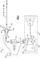
- FIG. 2 schematically illustrates an electro-pneumatic ECS air circuit 100 that reduces the inefficiencies associated with providing air from a compressor to an ECS.
- the electro-pneumatic ECS air circuit 100 includes multiple bleeds 102, 104, 106, 108 within a compressor section 122 of an engine 120. Each of the bleeds 102, 104, 106, 108 is connected to an intercooler 130 via a selection valve 140.
- the intercooler 130 operates as a heat exchanger to cool the bleed air.
- the bleeds 102, 104, 106, 108 are positioned at an inter-compressor stage between a low pressure compressor 122a, and a high pressure compressor 122b (bleed 102), and at a high pressure compressor 122b third stage (bleed 104), sixth stage (bleed 106), and eighth stage (bleed 108).
- the bleed locations can be positioned at, or between, alternative compressor stages, depending on the specific flow, temperature, and pressure requirements of the aircraft incorporating the engine 120.
- alternative numbers of bleeds can be utilized depending on the specific requirements of the aircraft.
- An aircraft controller 101 controls the selection valve 140 such that, at any given time, air is provided from a bleed 102, 104, 106, 108 having the appropriate flow requirements of the ECS at the current operating conditions of the aircraft. While the bleed 102, 104, 106, 108 selected by the controller 101 provides air at acceptable flow levels, the bleed 102, 104, 106, 108 is selected to provide air that is under pressured. In other words, the pressure of the air provided by the selected bleed 102, 104, 106, 108 is below the pressure required by the ECS. Further, the air selected exceeds the temperature requirements of the ECS.
- the intercooler 130 is a heat exchanger that cools the bleed air prior to providing the air to the ECS.
- the exemplary intercooler 130 utilizes fan air, provided from the bypass flowpath of the engine 120, to cool the air in a conventional air to air heat exchanger format.
- alternative style heat exchangers can be utilized as the intercooler 130 to similar effect.
- Cooled air from the intercooler 130 is provided to a second valve 150.
- the second valve 150 is controlled by the aircraft controller 101 and provides air to a first auxiliary compressor 160, a second auxiliary compressor 162, or both the first and second auxiliary compressor 160, 162.
- Each of the auxiliary compressors 160, 162 is driven by a corresponding electric motor 164, 166 and raises the pressure of the air to a required pressure level for provision to the ECS.
- one or both of the electric motors 164, 166 can be replaced or supplemented by a mechanical motor and/or a mechanical connection to a rotational source within the engine 120 or within the aircraft incorporating the engine 120.
- Once pressurized via the auxiliary compressors 160, 162 the air is provided to the ECS.
- a single auxiliary compressor 160 can be used in place of the first and second auxiliary compressors 160, 162.
- three or more auxiliary compressors can be included, with the controller 101 rotating between the auxiliary compressors as necessary.
- circuit 100 is illustrated in Figure 2 with a single engine 120, a similar circuit can be utilized with multiple engines 120, with the air from the bleeds 102, 104, 106, 108 of each engine 120, being mixed after being cooled in a corresponding intercooler 130.
- the air from each engine 120 can be mixed at alternate positions in the ECS air circuit 100 prior to provision to auxiliary compressors 160, 162.
- auxiliary compressors 160, 162 In the exemplary circuit 100 only one of the auxiliary compressors 160, 162 is required to provide sufficient pressurization to the ECS during standard operating conditions. As such, only a single auxiliary compressor 160, 162 is typically operated during a flight. In order to even out wear between the auxiliary compressors 160, 162 the primary operating auxiliary compressor 160, 162 is alternated between flights on a per flight basis. Alternating between auxiliary compressors 160, 162 further allows earlier detection, and correction, of a damaged or inoperable second auxiliary compressor 162.
- the air provided from the bleeds 102, 104, 106, 108 is reduced proportionally.
- the air provided to the auxiliary compressors 160, 162 is cut in half.
- the controller 101 can apply a proportional control to one or more of the auxiliary compressors to ensure that adequate pressure is maintained at the ECS in proportion to the pressure lost due to the lack of operation of the engine.
Landscapes
- Engineering & Computer Science (AREA)
- Chemical & Material Sciences (AREA)
- Combustion & Propulsion (AREA)
- Mechanical Engineering (AREA)
- General Engineering & Computer Science (AREA)
- Aviation & Aerospace Engineering (AREA)
- Fluid Mechanics (AREA)
- Physics & Mathematics (AREA)
- Health & Medical Sciences (AREA)
- General Health & Medical Sciences (AREA)
- Pulmonology (AREA)
- Power Engineering (AREA)
- Structures Of Non-Positive Displacement Pumps (AREA)
- Control Of Turbines (AREA)
Applications Claiming Priority (1)
| Application Number | Priority Date | Filing Date | Title |
|---|---|---|---|
| US201662432110P | 2016-12-09 | 2016-12-09 |
Publications (2)
| Publication Number | Publication Date |
|---|---|
| EP3333404A1 true EP3333404A1 (de) | 2018-06-13 |
| EP3333404B1 EP3333404B1 (de) | 2020-09-30 |
Family
ID=60661799
Family Applications (3)
| Application Number | Title | Priority Date | Filing Date |
|---|---|---|---|
| EP22203574.3A Active EP4155525B1 (de) | 2016-12-09 | 2017-10-31 | Luftkreislauf für klimaregelungssystem |
| EP17878477.3A Active EP3551537B1 (de) | 2016-12-09 | 2017-10-31 | Flugzeug und verfahren zur zufuhr von triebwerksluft an ein klimaregelungssystem |
| EP17206288.7A Active EP3333404B1 (de) | 2016-12-09 | 2017-12-08 | Elektropneumatisches luftführungssystem einer klimatisierung sowie verfahren |
Family Applications Before (2)
| Application Number | Title | Priority Date | Filing Date |
|---|---|---|---|
| EP22203574.3A Active EP4155525B1 (de) | 2016-12-09 | 2017-10-31 | Luftkreislauf für klimaregelungssystem |
| EP17878477.3A Active EP3551537B1 (de) | 2016-12-09 | 2017-10-31 | Flugzeug und verfahren zur zufuhr von triebwerksluft an ein klimaregelungssystem |
Country Status (3)
| Country | Link |
|---|---|
| US (3) | US20180162537A1 (de) |
| EP (3) | EP4155525B1 (de) |
| WO (1) | WO2018106359A1 (de) |
Cited By (1)
| Publication number | Priority date | Publication date | Assignee | Title |
|---|---|---|---|---|
| EP3628840A1 (de) * | 2018-09-25 | 2020-04-01 | Pratt & Whitney Canada Corp. | Mehrquellen-luftsystem und schaltventilanordnung dafür |
Families Citing this family (26)
| Publication number | Priority date | Publication date | Assignee | Title |
|---|---|---|---|---|
| US10578028B2 (en) * | 2015-08-18 | 2020-03-03 | General Electric Company | Compressor bleed auxiliary turbine |
| US10711702B2 (en) | 2015-08-18 | 2020-07-14 | General Electric Company | Mixed flow turbocore |
| US10711797B2 (en) | 2017-06-16 | 2020-07-14 | General Electric Company | Inlet pre-swirl gas turbine engine |
| US10815886B2 (en) * | 2017-06-16 | 2020-10-27 | General Electric Company | High tip speed gas turbine engine |
| US10794396B2 (en) | 2017-06-16 | 2020-10-06 | General Electric Company | Inlet pre-swirl gas turbine engine |
| US10724435B2 (en) | 2017-06-16 | 2020-07-28 | General Electric Co. | Inlet pre-swirl gas turbine engine |
| US11454175B2 (en) | 2019-02-05 | 2022-09-27 | Raytheon Technologies Corporation | Power assisted engine start bleed system |
| FR3096396B1 (fr) * | 2019-05-24 | 2021-04-23 | Safran Aircraft Engines | système HYDROMECANIQUE DE REGULATION D’HUILE DE LUBRIFICATION D’UNE TURBOMACHINE AVEC REGULATION DU DEBIT D’HUILE |
| US11215124B2 (en) | 2019-08-27 | 2022-01-04 | Pratt & Whitney Canada Corp. | System and method for conditioning a fluid using bleed air from a bypass duct of a turbofan engine |
| US11390386B2 (en) | 2019-08-27 | 2022-07-19 | Pratt & Whitney Canada Corp. | System and method for increasing bleed air flow to a heat exchanger with a fluid-driven fluid propeller |
| EP3882152A1 (de) | 2020-03-17 | 2021-09-22 | Hamilton Sundstrand Corporation | Elektro-pneumatisch angetriebenes klimaregelungssystem |
| US20230399111A1 (en) * | 2020-10-28 | 2023-12-14 | Kawasaki Jukogyo Kabushiki Kaisha | Compressed air supply system of aircraft |
| JP7473924B2 (ja) * | 2020-10-28 | 2024-04-24 | 川崎重工業株式会社 | 航空機用のガスタービンエンジン |
| EP4239172A4 (de) * | 2020-10-28 | 2024-07-10 | Kawasaki Jukogyo Kabushiki Kaisha | Druckluftversorgungsanlage |
| CN112503607B (zh) * | 2020-10-30 | 2022-09-06 | 广西电网有限责任公司电力科学研究院 | 一种适于电联产机组的电驱动蒸汽升压供热装置 |
| US11486315B2 (en) * | 2020-11-06 | 2022-11-01 | Ge Aviation Systems Llc | Combustion engine including turbomachine |
| US11428160B2 (en) | 2020-12-31 | 2022-08-30 | General Electric Company | Gas turbine engine with interdigitated turbine and gear assembly |
| US20230228216A1 (en) * | 2022-01-19 | 2023-07-20 | General Electric Company | Bleed flow assembly for a gas turbine engine |
| US12215628B2 (en) * | 2022-07-22 | 2025-02-04 | Rtx Corporation | Aircraft system with gas turbine engine powered compressor |
| US11674438B1 (en) * | 2022-10-03 | 2023-06-13 | General Electric Company | Thermal management system |
| US12435667B2 (en) | 2023-06-16 | 2025-10-07 | Pratt & Whitney Canada Corp. | Aircraft air system with dedicated compressor(s) |
| US12503241B2 (en) * | 2024-04-23 | 2025-12-23 | Rtx Corporation | Thermal management assembly for an aircraft propulsion system |
| US12410748B1 (en) * | 2024-05-21 | 2025-09-09 | Rtx Corporation | Boost compressor augmentation for hybrid electric thermal management systems |
| US20260035082A1 (en) * | 2024-08-01 | 2026-02-05 | Rtx Corporation | Low spool electrical machine arrangements for hybrid-electric engines |
| US12428988B1 (en) | 2024-08-16 | 2025-09-30 | General Electric Company | High temperature anti-ice systems for aircraft engines |
| US12435668B1 (en) | 2024-11-01 | 2025-10-07 | General Electric Company | Methods and apparatus for anti-ice heat supply from waste heat recovery systems |
Citations (6)
| Publication number | Priority date | Publication date | Assignee | Title |
|---|---|---|---|---|
| US5452573A (en) * | 1994-01-31 | 1995-09-26 | United Technologies Corporation | High pressure air source for aircraft and engine requirements |
| US6189324B1 (en) * | 1999-10-05 | 2001-02-20 | Samuel B. Williams | Environment control unit for turbine engine |
| US8397487B2 (en) * | 2011-02-28 | 2013-03-19 | General Electric Company | Environmental control system supply precooler bypass |
| US20150233291A1 (en) * | 2014-02-17 | 2015-08-20 | Airbus Operations (Sas) | Turbojet comprising a bleeding system for bleeding air in said turbojet |
| US20150354464A1 (en) * | 2014-06-09 | 2015-12-10 | Rolls-Royce Plc | Method and apparatus for controlling a compressor of a gas turbine engine |
| EP2960467A1 (de) * | 2014-06-27 | 2015-12-30 | Frederick M. Schwarz | Niederdruckzapfluftentnahme für klimatisierungssystem eines flugzeugs |
Family Cites Families (61)
| Publication number | Priority date | Publication date | Assignee | Title |
|---|---|---|---|---|
| US4474001A (en) | 1981-04-01 | 1984-10-02 | United Technologies Corporation | Cooling system for the electrical generator of a turbofan gas turbine engine |
| GB8907706D0 (en) * | 1989-04-05 | 1989-05-17 | Rolls Royce Plc | An axial flow compressor |
| GB2234805A (en) | 1989-08-04 | 1991-02-13 | Rolls Royce Plc | A heat exchanger arrangement for a gas turbine engine |
| US5141182A (en) * | 1990-06-01 | 1992-08-25 | General Electric Company | Gas turbine engine fan duct base pressure drag reduction |
| US5203163A (en) | 1990-08-01 | 1993-04-20 | General Electric Company | Heat exchange arrangement in a gas turbine engine fan duct for cooling hot bleed air |
| US5063963A (en) * | 1990-08-09 | 1991-11-12 | General Electric Company | Engine bleed air supply system |
| US5137230A (en) * | 1991-06-04 | 1992-08-11 | General Electric Company | Aircraft gas turbine engine bleed air energy recovery apparatus |
| US5363641A (en) * | 1993-08-06 | 1994-11-15 | United Technologies Corporation | Integrated auxiliary power system |
| US6926490B2 (en) * | 2003-01-21 | 2005-08-09 | Hamilton Sundstrand | Self-actuated bearing cooling flow shut-off valve |
| US7578136B2 (en) * | 2004-08-23 | 2009-08-25 | Honeywell International Inc. | Integrated power and pressurization system |
| US7059136B2 (en) * | 2004-08-27 | 2006-06-13 | General Electric Company | Air turbine powered accessory |
| US7171819B2 (en) * | 2005-01-21 | 2007-02-06 | Honeywell International, Inc. | Indirect regenerative air cycle for integrated power and cooling machines |
| FR2889250B1 (fr) | 2005-07-28 | 2007-09-07 | Airbus France Sas | Ensemble propulseur pour aeronef et aeronef comportant au moins un tel ensemble propulseur |
| US20070022735A1 (en) * | 2005-07-29 | 2007-02-01 | General Electric Company | Pto assembly for a gas turbine engine |
| US8776952B2 (en) * | 2006-05-11 | 2014-07-15 | United Technologies Corporation | Thermal management system for turbofan engines |
| US7607318B2 (en) * | 2006-05-25 | 2009-10-27 | Honeywell International Inc. | Integrated environmental control and auxiliary power system for an aircraft |
| US7765788B2 (en) | 2006-07-06 | 2010-08-03 | United Technologies Corporation | Cooling exchanger duct |
| US7690188B2 (en) * | 2007-03-02 | 2010-04-06 | United Technologies Corporation | Combination engines for aircraft |
| US7856824B2 (en) | 2007-06-25 | 2010-12-28 | Honeywell International Inc. | Cooling systems for use on aircraft |
| US9234481B2 (en) | 2008-01-25 | 2016-01-12 | United Technologies Corporation | Shared flow thermal management system |
| US8529189B2 (en) * | 2009-01-30 | 2013-09-10 | Honeywell International Inc. | Linear quadratic regulator control for bleed air system fan air valve |
| US8266888B2 (en) | 2010-06-24 | 2012-09-18 | Pratt & Whitney Canada Corp. | Cooler in nacelle with radial coolant |
| US20120045317A1 (en) * | 2010-08-23 | 2012-02-23 | Honeywell International Inc. | Fuel actuated bleed air system |
| US8471702B2 (en) * | 2010-12-22 | 2013-06-25 | General Electric Company | Method and system for compressor health monitoring |
| US20130040545A1 (en) * | 2011-08-11 | 2013-02-14 | Hamilton Sundstrand Corporation | Low pressure compressor bleed exit for an aircraft pressurization system |
| US9003814B2 (en) * | 2011-11-11 | 2015-04-14 | Hamilton Sundstrand Corporation | Turbo air compressor with pressure recovery |
| US8904805B2 (en) | 2012-01-09 | 2014-12-09 | United Technologies Corporation | Environmental control system for aircraft utilizing turbo-compressor |
| US9416677B2 (en) * | 2012-01-10 | 2016-08-16 | United Technologies Corporation | Gas turbine engine forward bearing compartment architecture |
| US8967528B2 (en) * | 2012-01-24 | 2015-03-03 | The Boeing Company | Bleed air systems for use with aircrafts and related methods |
| US8955794B2 (en) * | 2012-01-24 | 2015-02-17 | The Boeing Company | Bleed air systems for use with aircrafts and related methods |
| US10724431B2 (en) * | 2012-01-31 | 2020-07-28 | Raytheon Technologies Corporation | Buffer system that communicates buffer supply air to one or more portions of a gas turbine engine |
| US8794009B2 (en) * | 2012-01-31 | 2014-08-05 | United Technologies Corporation | Gas turbine engine buffer system |
| CA2891071C (fr) * | 2012-11-09 | 2022-04-26 | Snecma | Procede et systeme de determination de debit d'air preleve sur un moteur d'aeronef |
| US9261046B2 (en) * | 2013-01-21 | 2016-02-16 | Lockheed Martin Corporation | Gas turbine exhaust noise reduction |
| EP2951419B1 (de) | 2013-01-29 | 2018-09-05 | United Technologies Corporation | Gasturbinenmotor mit einem wärmetauscher in einer unteren gabelung |
| US9422063B2 (en) | 2013-05-31 | 2016-08-23 | General Electric Company | Cooled cooling air system for a gas turbine |
| US10184494B2 (en) * | 2013-06-28 | 2019-01-22 | Hamilton Sundstrand Corporation | Enhance motor cooling system and method |
| WO2015047533A1 (en) | 2013-09-24 | 2015-04-02 | United Technologies Corporation | Bypass duct heat exchanger placement |
| GB201318572D0 (en) * | 2013-10-21 | 2013-12-04 | Rolls Royce Plc | Pneumatic system for an aircraft |
| GB201319563D0 (en) * | 2013-11-06 | 2013-12-18 | Rolls Royce Plc | Pneumatic system for an aircraft |
| FR3015573B1 (fr) | 2013-12-19 | 2015-12-11 | Snecma | Turbomachine d'aeronef comportant un echangeur de chaleur du type pre-refroidisseur |
| US9656756B2 (en) * | 2014-03-10 | 2017-05-23 | The Boeing Company | Turbo-compressor system and method for extracting energy from an aircraft engine |
| US9810158B2 (en) * | 2014-04-01 | 2017-11-07 | The Boeing Company | Bleed air systems for use with aircraft and related methods |
| GB201415078D0 (en) * | 2014-08-26 | 2014-10-08 | Rolls Royce Plc | Gas turbine engine anti-icing system |
| GB201506398D0 (en) * | 2014-12-11 | 2015-05-27 | Rolls Royce Plc | Cabin blower system |
| US10421551B2 (en) * | 2014-12-15 | 2019-09-24 | United Technologies Corporation | Aircraft anti-icing system |
| US10830543B2 (en) | 2015-02-06 | 2020-11-10 | Raytheon Technologies Corporation | Additively manufactured ducted heat exchanger system with additively manufactured header |
| US10006370B2 (en) | 2015-02-12 | 2018-06-26 | United Technologies Corporation | Intercooled cooling air with heat exchanger packaging |
| US20170082028A1 (en) | 2015-02-12 | 2017-03-23 | United Technologies Corporation | Intercooled cooling air using existing heat exchanger |
| CA2932250C (en) * | 2015-06-04 | 2023-07-18 | Hamilton Sundstrand Corporation | Environmental control system with multiple operation modes |
| US20160369697A1 (en) | 2015-06-16 | 2016-12-22 | United Technologies Corporation | Cooled cooling air system for a turbofan engine |
| US10100744B2 (en) * | 2015-06-19 | 2018-10-16 | The Boeing Company | Aircraft bleed air and engine starter systems and related methods |
| EP3130539B1 (de) | 2015-08-12 | 2020-04-08 | Rolls-Royce North American Technologies, Inc. | Wärmetauscher für ein gasturbinenmotorantriebssystem |
| US10227929B2 (en) * | 2015-10-13 | 2019-03-12 | Honeywell International Inc. | Flow limiting duct vent valves and gas turbine engine bleed air systems including the same |
| GB201518788D0 (en) | 2015-10-23 | 2015-12-09 | Rolls Royce Plc | Aircraft pneumatic system |
| US20170241340A1 (en) * | 2016-02-19 | 2017-08-24 | United Technologies Corporation | Turbocompressor for aircraft environmental control system |
| US10161783B2 (en) * | 2016-04-12 | 2018-12-25 | Hamilton Sundstrand Corporation | Flow sensor bit for motor driven compressor |
| US20180009536A1 (en) * | 2016-07-11 | 2018-01-11 | General Electric Company | Bleed flow extraction system for a gas turbine engine |
| US20180057171A1 (en) * | 2016-08-23 | 2018-03-01 | Ge Aviation Systems, Llc | Advanced method and aircraft for pre-cooling an environmental control system using a three wheel turbo-machine |
| CA3038718C (en) * | 2016-09-29 | 2023-12-05 | Airbus Operations, S.L. | Auxiliary air supply for an aircraft |
| US10661907B2 (en) * | 2016-11-17 | 2020-05-26 | Honeywell International Inc. | Hybrid pneumatic and electric secondary power integrated cabin energy system for a pressurized vehicle |
-
2017
- 2017-08-01 US US15/665,860 patent/US20180162537A1/en not_active Abandoned
- 2017-10-31 EP EP22203574.3A patent/EP4155525B1/de active Active
- 2017-10-31 WO PCT/US2017/059150 patent/WO2018106359A1/en not_active Ceased
- 2017-10-31 EP EP17878477.3A patent/EP3551537B1/de active Active
- 2017-11-10 US US15/809,244 patent/US11130580B2/en active Active
- 2017-12-08 EP EP17206288.7A patent/EP3333404B1/de active Active
-
2021
- 2021-08-25 US US17/411,529 patent/US11518525B2/en active Active
Patent Citations (6)
| Publication number | Priority date | Publication date | Assignee | Title |
|---|---|---|---|---|
| US5452573A (en) * | 1994-01-31 | 1995-09-26 | United Technologies Corporation | High pressure air source for aircraft and engine requirements |
| US6189324B1 (en) * | 1999-10-05 | 2001-02-20 | Samuel B. Williams | Environment control unit for turbine engine |
| US8397487B2 (en) * | 2011-02-28 | 2013-03-19 | General Electric Company | Environmental control system supply precooler bypass |
| US20150233291A1 (en) * | 2014-02-17 | 2015-08-20 | Airbus Operations (Sas) | Turbojet comprising a bleeding system for bleeding air in said turbojet |
| US20150354464A1 (en) * | 2014-06-09 | 2015-12-10 | Rolls-Royce Plc | Method and apparatus for controlling a compressor of a gas turbine engine |
| EP2960467A1 (de) * | 2014-06-27 | 2015-12-30 | Frederick M. Schwarz | Niederdruckzapfluftentnahme für klimatisierungssystem eines flugzeugs |
Cited By (2)
| Publication number | Priority date | Publication date | Assignee | Title |
|---|---|---|---|---|
| EP3628840A1 (de) * | 2018-09-25 | 2020-04-01 | Pratt & Whitney Canada Corp. | Mehrquellen-luftsystem und schaltventilanordnung dafür |
| US11008949B2 (en) | 2018-09-25 | 2021-05-18 | Pratt & Whitney Canada Corp. | Multi-source air system and switching valve assembly for a gas turbine engine |
Also Published As
| Publication number | Publication date |
|---|---|
| US11130580B2 (en) | 2021-09-28 |
| EP4155525A1 (de) | 2023-03-29 |
| EP3551537A1 (de) | 2019-10-16 |
| EP3551537B1 (de) | 2022-10-26 |
| EP4155525B1 (de) | 2025-07-16 |
| US20210380260A1 (en) | 2021-12-09 |
| US20180163627A1 (en) | 2018-06-14 |
| US20180162537A1 (en) | 2018-06-14 |
| EP3333404B1 (de) | 2020-09-30 |
| US11518525B2 (en) | 2022-12-06 |
| WO2018106359A1 (en) | 2018-06-14 |
| EP3551537A4 (de) | 2019-11-20 |
Similar Documents
| Publication | Publication Date | Title |
|---|---|---|
| US11518525B2 (en) | Electro-pneumatic environmental control system air circuit | |
| US10731563B2 (en) | Compressed air bleed supply for buffer system | |
| EP3690213B1 (de) | Flugzeugklimaanlagensteuerung | |
| US10830149B2 (en) | Intercooled cooling air using cooling compressor as starter | |
| EP3584427B1 (de) | Zwischengekühltes kühlluftsystem mit niedrigtemperaturluft für lagerkammer | |
| EP3228843B1 (de) | Integriertes umweltkontroll- und -puffersystem für flugzeug | |
| EP2966279B1 (de) | Hybridverdichterzapfluft für den einsatz in flugzeugen | |
| EP3228844A1 (de) | Integrierte umgebungskontrolle und pufferluftsystem | |
| EP3572645B1 (de) | Verbesserte nachgeschaltete turbinenschaufelkühlung für einen gasturbinenmotor | |
| EP3604766B1 (de) | Zwischengekühlte kühlluft mit selektiver druckentlastung | |
| EP3533988A1 (de) | Zwischengekühlte kühlluft |
Legal Events
| Date | Code | Title | Description |
|---|---|---|---|
| PUAI | Public reference made under article 153(3) epc to a published international application that has entered the european phase |
Free format text: ORIGINAL CODE: 0009012 |
|
| STAA | Information on the status of an ep patent application or granted ep patent |
Free format text: STATUS: THE APPLICATION HAS BEEN PUBLISHED |
|
| AK | Designated contracting states |
Kind code of ref document: A1 Designated state(s): AL AT BE BG CH CY CZ DE DK EE ES FI FR GB GR HR HU IE IS IT LI LT LU LV MC MK MT NL NO PL PT RO RS SE SI SK SM TR |
|
| AX | Request for extension of the european patent |
Extension state: BA ME |
|
| STAA | Information on the status of an ep patent application or granted ep patent |
Free format text: STATUS: REQUEST FOR EXAMINATION WAS MADE |
|
| 17P | Request for examination filed |
Effective date: 20181213 |
|
| RBV | Designated contracting states (corrected) |
Designated state(s): AL AT BE BG CH CY CZ DE DK EE ES FI FR GB GR HR HU IE IS IT LI LT LU LV MC MK MT NL NO PL PT RO RS SE SI SK SM TR |
|
| GRAP | Despatch of communication of intention to grant a patent |
Free format text: ORIGINAL CODE: EPIDOSNIGR1 |
|
| STAA | Information on the status of an ep patent application or granted ep patent |
Free format text: STATUS: GRANT OF PATENT IS INTENDED |
|
| INTG | Intention to grant announced |
Effective date: 20200414 |
|
| GRAS | Grant fee paid |
Free format text: ORIGINAL CODE: EPIDOSNIGR3 |
|
| GRAA | (expected) grant |
Free format text: ORIGINAL CODE: 0009210 |
|
| STAA | Information on the status of an ep patent application or granted ep patent |
Free format text: STATUS: THE PATENT HAS BEEN GRANTED |
|
| AK | Designated contracting states |
Kind code of ref document: B1 Designated state(s): AL AT BE BG CH CY CZ DE DK EE ES FI FR GB GR HR HU IE IS IT LI LT LU LV MC MK MT NL NO PL PT RO RS SE SI SK SM TR |
|
| REG | Reference to a national code |
Ref country code: GB Ref legal event code: FG4D Ref country code: CH Ref legal event code: EP |
|
| REG | Reference to a national code |
Ref country code: AT Ref legal event code: REF Ref document number: 1319030 Country of ref document: AT Kind code of ref document: T Effective date: 20201015 |
|
| REG | Reference to a national code |
Ref country code: DE Ref legal event code: R096 Ref document number: 602017024527 Country of ref document: DE |
|
| REG | Reference to a national code |
Ref country code: IE Ref legal event code: FG4D |
|
| PG25 | Lapsed in a contracting state [announced via postgrant information from national office to epo] |
Ref country code: NO Free format text: LAPSE BECAUSE OF FAILURE TO SUBMIT A TRANSLATION OF THE DESCRIPTION OR TO PAY THE FEE WITHIN THE PRESCRIBED TIME-LIMIT Effective date: 20201230 Ref country code: HR Free format text: LAPSE BECAUSE OF FAILURE TO SUBMIT A TRANSLATION OF THE DESCRIPTION OR TO PAY THE FEE WITHIN THE PRESCRIBED TIME-LIMIT Effective date: 20200930 Ref country code: GR Free format text: LAPSE BECAUSE OF FAILURE TO SUBMIT A TRANSLATION OF THE DESCRIPTION OR TO PAY THE FEE WITHIN THE PRESCRIBED TIME-LIMIT Effective date: 20201231 Ref country code: SE Free format text: LAPSE BECAUSE OF FAILURE TO SUBMIT A TRANSLATION OF THE DESCRIPTION OR TO PAY THE FEE WITHIN THE PRESCRIBED TIME-LIMIT Effective date: 20200930 Ref country code: BG Free format text: LAPSE BECAUSE OF FAILURE TO SUBMIT A TRANSLATION OF THE DESCRIPTION OR TO PAY THE FEE WITHIN THE PRESCRIBED TIME-LIMIT Effective date: 20201230 Ref country code: FI Free format text: LAPSE BECAUSE OF FAILURE TO SUBMIT A TRANSLATION OF THE DESCRIPTION OR TO PAY THE FEE WITHIN THE PRESCRIBED TIME-LIMIT Effective date: 20200930 |
|
| REG | Reference to a national code |
Ref country code: AT Ref legal event code: MK05 Ref document number: 1319030 Country of ref document: AT Kind code of ref document: T Effective date: 20200930 |
|
| PG25 | Lapsed in a contracting state [announced via postgrant information from national office to epo] |
Ref country code: RS Free format text: LAPSE BECAUSE OF FAILURE TO SUBMIT A TRANSLATION OF THE DESCRIPTION OR TO PAY THE FEE WITHIN THE PRESCRIBED TIME-LIMIT Effective date: 20200930 Ref country code: LV Free format text: LAPSE BECAUSE OF FAILURE TO SUBMIT A TRANSLATION OF THE DESCRIPTION OR TO PAY THE FEE WITHIN THE PRESCRIBED TIME-LIMIT Effective date: 20200930 |
|
| REG | Reference to a national code |
Ref country code: NL Ref legal event code: MP Effective date: 20200930 |
|
| RAP2 | Party data changed (patent owner data changed or rights of a patent transferred) |
Owner name: RAYTHEON TECHNOLOGIES CORPORATION |
|
| REG | Reference to a national code |
Ref country code: LT Ref legal event code: MG4D |
|
| PG25 | Lapsed in a contracting state [announced via postgrant information from national office to epo] |
Ref country code: EE Free format text: LAPSE BECAUSE OF FAILURE TO SUBMIT A TRANSLATION OF THE DESCRIPTION OR TO PAY THE FEE WITHIN THE PRESCRIBED TIME-LIMIT Effective date: 20200930 Ref country code: SM Free format text: LAPSE BECAUSE OF FAILURE TO SUBMIT A TRANSLATION OF THE DESCRIPTION OR TO PAY THE FEE WITHIN THE PRESCRIBED TIME-LIMIT Effective date: 20200930 Ref country code: LT Free format text: LAPSE BECAUSE OF FAILURE TO SUBMIT A TRANSLATION OF THE DESCRIPTION OR TO PAY THE FEE WITHIN THE PRESCRIBED TIME-LIMIT Effective date: 20200930 Ref country code: PT Free format text: LAPSE BECAUSE OF FAILURE TO SUBMIT A TRANSLATION OF THE DESCRIPTION OR TO PAY THE FEE WITHIN THE PRESCRIBED TIME-LIMIT Effective date: 20210201 Ref country code: RO Free format text: LAPSE BECAUSE OF FAILURE TO SUBMIT A TRANSLATION OF THE DESCRIPTION OR TO PAY THE FEE WITHIN THE PRESCRIBED TIME-LIMIT Effective date: 20200930 Ref country code: CZ Free format text: LAPSE BECAUSE OF FAILURE TO SUBMIT A TRANSLATION OF THE DESCRIPTION OR TO PAY THE FEE WITHIN THE PRESCRIBED TIME-LIMIT Effective date: 20200930 |
|
| PG25 | Lapsed in a contracting state [announced via postgrant information from national office to epo] |
Ref country code: PL Free format text: LAPSE BECAUSE OF FAILURE TO SUBMIT A TRANSLATION OF THE DESCRIPTION OR TO PAY THE FEE WITHIN THE PRESCRIBED TIME-LIMIT Effective date: 20200930 Ref country code: IS Free format text: LAPSE BECAUSE OF FAILURE TO SUBMIT A TRANSLATION OF THE DESCRIPTION OR TO PAY THE FEE WITHIN THE PRESCRIBED TIME-LIMIT Effective date: 20210130 Ref country code: AT Free format text: LAPSE BECAUSE OF FAILURE TO SUBMIT A TRANSLATION OF THE DESCRIPTION OR TO PAY THE FEE WITHIN THE PRESCRIBED TIME-LIMIT Effective date: 20200930 Ref country code: AL Free format text: LAPSE BECAUSE OF FAILURE TO SUBMIT A TRANSLATION OF THE DESCRIPTION OR TO PAY THE FEE WITHIN THE PRESCRIBED TIME-LIMIT Effective date: 20200930 Ref country code: ES Free format text: LAPSE BECAUSE OF FAILURE TO SUBMIT A TRANSLATION OF THE DESCRIPTION OR TO PAY THE FEE WITHIN THE PRESCRIBED TIME-LIMIT Effective date: 20200930 |
|
| PG25 | Lapsed in a contracting state [announced via postgrant information from national office to epo] |
Ref country code: NL Free format text: LAPSE BECAUSE OF FAILURE TO SUBMIT A TRANSLATION OF THE DESCRIPTION OR TO PAY THE FEE WITHIN THE PRESCRIBED TIME-LIMIT Effective date: 20200930 Ref country code: SK Free format text: LAPSE BECAUSE OF FAILURE TO SUBMIT A TRANSLATION OF THE DESCRIPTION OR TO PAY THE FEE WITHIN THE PRESCRIBED TIME-LIMIT Effective date: 20200930 |
|
| REG | Reference to a national code |
Ref country code: DE Ref legal event code: R097 Ref document number: 602017024527 Country of ref document: DE |
|
| REG | Reference to a national code |
Ref country code: CH Ref legal event code: PL |
|
| PLBE | No opposition filed within time limit |
Free format text: ORIGINAL CODE: 0009261 |
|
| STAA | Information on the status of an ep patent application or granted ep patent |
Free format text: STATUS: NO OPPOSITION FILED WITHIN TIME LIMIT |
|
| PG25 | Lapsed in a contracting state [announced via postgrant information from national office to epo] |
Ref country code: DK Free format text: LAPSE BECAUSE OF FAILURE TO SUBMIT A TRANSLATION OF THE DESCRIPTION OR TO PAY THE FEE WITHIN THE PRESCRIBED TIME-LIMIT Effective date: 20200930 Ref country code: MC Free format text: LAPSE BECAUSE OF FAILURE TO SUBMIT A TRANSLATION OF THE DESCRIPTION OR TO PAY THE FEE WITHIN THE PRESCRIBED TIME-LIMIT Effective date: 20200930 |
|
| REG | Reference to a national code |
Ref country code: BE Ref legal event code: MM Effective date: 20201231 |
|
| 26N | No opposition filed |
Effective date: 20210701 |
|
| PG25 | Lapsed in a contracting state [announced via postgrant information from national office to epo] |
Ref country code: LU Free format text: LAPSE BECAUSE OF NON-PAYMENT OF DUE FEES Effective date: 20201208 Ref country code: IT Free format text: LAPSE BECAUSE OF FAILURE TO SUBMIT A TRANSLATION OF THE DESCRIPTION OR TO PAY THE FEE WITHIN THE PRESCRIBED TIME-LIMIT Effective date: 20200930 Ref country code: IE Free format text: LAPSE BECAUSE OF NON-PAYMENT OF DUE FEES Effective date: 20201208 |
|
| PG25 | Lapsed in a contracting state [announced via postgrant information from national office to epo] |
Ref country code: LI Free format text: LAPSE BECAUSE OF NON-PAYMENT OF DUE FEES Effective date: 20201231 Ref country code: SI Free format text: LAPSE BECAUSE OF FAILURE TO SUBMIT A TRANSLATION OF THE DESCRIPTION OR TO PAY THE FEE WITHIN THE PRESCRIBED TIME-LIMIT Effective date: 20200930 Ref country code: CH Free format text: LAPSE BECAUSE OF NON-PAYMENT OF DUE FEES Effective date: 20201231 |
|
| PG25 | Lapsed in a contracting state [announced via postgrant information from national office to epo] |
Ref country code: IS Free format text: LAPSE BECAUSE OF FAILURE TO SUBMIT A TRANSLATION OF THE DESCRIPTION OR TO PAY THE FEE WITHIN THE PRESCRIBED TIME-LIMIT Effective date: 20210130 Ref country code: TR Free format text: LAPSE BECAUSE OF FAILURE TO SUBMIT A TRANSLATION OF THE DESCRIPTION OR TO PAY THE FEE WITHIN THE PRESCRIBED TIME-LIMIT Effective date: 20200930 Ref country code: MT Free format text: LAPSE BECAUSE OF FAILURE TO SUBMIT A TRANSLATION OF THE DESCRIPTION OR TO PAY THE FEE WITHIN THE PRESCRIBED TIME-LIMIT Effective date: 20200930 Ref country code: CY Free format text: LAPSE BECAUSE OF FAILURE TO SUBMIT A TRANSLATION OF THE DESCRIPTION OR TO PAY THE FEE WITHIN THE PRESCRIBED TIME-LIMIT Effective date: 20200930 |
|
| PG25 | Lapsed in a contracting state [announced via postgrant information from national office to epo] |
Ref country code: MK Free format text: LAPSE BECAUSE OF FAILURE TO SUBMIT A TRANSLATION OF THE DESCRIPTION OR TO PAY THE FEE WITHIN THE PRESCRIBED TIME-LIMIT Effective date: 20200930 |
|
| PG25 | Lapsed in a contracting state [announced via postgrant information from national office to epo] |
Ref country code: BE Free format text: LAPSE BECAUSE OF NON-PAYMENT OF DUE FEES Effective date: 20201231 |
|
| P01 | Opt-out of the competence of the unified patent court (upc) registered |
Effective date: 20230520 |
|
| REG | Reference to a national code |
Ref country code: DE Ref legal event code: R081 Ref document number: 602017024527 Country of ref document: DE Owner name: RTX CORPORATION (N.D.GES.D. STAATES DELAWARE),, US Free format text: FORMER OWNER: UNITED TECHNOLOGIES CORPORATION, FARMINGTON, CONN., US |
|
| PGFP | Annual fee paid to national office [announced via postgrant information from national office to epo] |
Ref country code: DE Payment date: 20251126 Year of fee payment: 9 |
|
| PGFP | Annual fee paid to national office [announced via postgrant information from national office to epo] |
Ref country code: GB Payment date: 20251119 Year of fee payment: 9 |
|
| PGFP | Annual fee paid to national office [announced via postgrant information from national office to epo] |
Ref country code: FR Payment date: 20251120 Year of fee payment: 9 |