EP3333393A1 - Verfahren und vorrichtung zur kontrolle der entnahmen aus einer turbomaschine zur begrenzung des pumprisikos durch informationsaustausch zwischen einem energiemanager und einem regelungssystem der turbomaschine - Google Patents
Verfahren und vorrichtung zur kontrolle der entnahmen aus einer turbomaschine zur begrenzung des pumprisikos durch informationsaustausch zwischen einem energiemanager und einem regelungssystem der turbomaschine Download PDFInfo
- Publication number
- EP3333393A1 EP3333393A1 EP17205590.7A EP17205590A EP3333393A1 EP 3333393 A1 EP3333393 A1 EP 3333393A1 EP 17205590 A EP17205590 A EP 17205590A EP 3333393 A1 EP3333393 A1 EP 3333393A1
- Authority
- EP
- European Patent Office
- Prior art keywords
- turbomachine
- pumping
- sampling
- air
- energy
- Prior art date
- Legal status (The legal status is an assumption and is not a legal conclusion. Google has not performed a legal analysis and makes no representation as to the accuracy of the status listed.)
- Granted
Links
Images


Classifications
-
- F—MECHANICAL ENGINEERING; LIGHTING; HEATING; WEAPONS; BLASTING
- F02—COMBUSTION ENGINES; HOT-GAS OR COMBUSTION-PRODUCT ENGINE PLANTS
- F02C—GAS-TURBINE PLANTS; AIR INTAKES FOR JET-PROPULSION PLANTS; CONTROLLING FUEL SUPPLY IN AIR-BREATHING JET-PROPULSION PLANTS
- F02C7/00—Features, components parts, details or accessories, not provided for in, or of interest apart form groups F02C1/00 - F02C6/00; Air intakes for jet-propulsion plants
- F02C7/32—Arrangement, mounting, or driving, of auxiliaries
-
- F—MECHANICAL ENGINEERING; LIGHTING; HEATING; WEAPONS; BLASTING
- F02—COMBUSTION ENGINES; HOT-GAS OR COMBUSTION-PRODUCT ENGINE PLANTS
- F02C—GAS-TURBINE PLANTS; AIR INTAKES FOR JET-PROPULSION PLANTS; CONTROLLING FUEL SUPPLY IN AIR-BREATHING JET-PROPULSION PLANTS
- F02C9/00—Controlling gas-turbine plants; Controlling fuel supply in air- breathing jet-propulsion plants
-
- F—MECHANICAL ENGINEERING; LIGHTING; HEATING; WEAPONS; BLASTING
- F04—POSITIVE - DISPLACEMENT MACHINES FOR LIQUIDS; PUMPS FOR LIQUIDS OR ELASTIC FLUIDS
- F04D—NON-POSITIVE-DISPLACEMENT PUMPS
- F04D27/00—Control, e.g. regulation, of pumps, pumping installations or pumping systems specially adapted for elastic fluids
- F04D27/001—Testing thereof; Determination or simulation of flow characteristics; Stall or surge detection, e.g. condition monitoring
-
- F—MECHANICAL ENGINEERING; LIGHTING; HEATING; WEAPONS; BLASTING
- F01—MACHINES OR ENGINES IN GENERAL; ENGINE PLANTS IN GENERAL; STEAM ENGINES
- F01D—NON-POSITIVE DISPLACEMENT MACHINES OR ENGINES, e.g. STEAM TURBINES
- F01D21/00—Shutting-down of machines or engines, e.g. in emergency; Regulating, controlling, or safety means not otherwise provided for
- F01D21/003—Arrangements for testing or measuring
-
- F—MECHANICAL ENGINEERING; LIGHTING; HEATING; WEAPONS; BLASTING
- F02—COMBUSTION ENGINES; HOT-GAS OR COMBUSTION-PRODUCT ENGINE PLANTS
- F02C—GAS-TURBINE PLANTS; AIR INTAKES FOR JET-PROPULSION PLANTS; CONTROLLING FUEL SUPPLY IN AIR-BREATHING JET-PROPULSION PLANTS
- F02C3/00—Gas-turbine plants characterised by the use of combustion products as the working fluid
- F02C3/04—Gas-turbine plants characterised by the use of combustion products as the working fluid having a turbine driving a compressor
-
- F—MECHANICAL ENGINEERING; LIGHTING; HEATING; WEAPONS; BLASTING
- F02—COMBUSTION ENGINES; HOT-GAS OR COMBUSTION-PRODUCT ENGINE PLANTS
- F02C—GAS-TURBINE PLANTS; AIR INTAKES FOR JET-PROPULSION PLANTS; CONTROLLING FUEL SUPPLY IN AIR-BREATHING JET-PROPULSION PLANTS
- F02C9/00—Controlling gas-turbine plants; Controlling fuel supply in air- breathing jet-propulsion plants
- F02C9/16—Control of working fluid flow
- F02C9/18—Control of working fluid flow by bleeding, bypassing or acting on variable working fluid interconnections between turbines or compressors or their stages
-
- F—MECHANICAL ENGINEERING; LIGHTING; HEATING; WEAPONS; BLASTING
- F04—POSITIVE - DISPLACEMENT MACHINES FOR LIQUIDS; PUMPS FOR LIQUIDS OR ELASTIC FLUIDS
- F04D—NON-POSITIVE-DISPLACEMENT PUMPS
- F04D15/00—Control, e.g. regulation, of pumps, pumping installations or systems
- F04D15/0088—Testing machines
-
- F—MECHANICAL ENGINEERING; LIGHTING; HEATING; WEAPONS; BLASTING
- F04—POSITIVE - DISPLACEMENT MACHINES FOR LIQUIDS; PUMPS FOR LIQUIDS OR ELASTIC FLUIDS
- F04D—NON-POSITIVE-DISPLACEMENT PUMPS
- F04D27/00—Control, e.g. regulation, of pumps, pumping installations or pumping systems specially adapted for elastic fluids
- F04D27/02—Surge control
- F04D27/0207—Surge control by bleeding, bypassing or recycling fluids
- F04D27/0223—Control schemes therefor
-
- F—MECHANICAL ENGINEERING; LIGHTING; HEATING; WEAPONS; BLASTING
- F05—INDEXING SCHEMES RELATING TO ENGINES OR PUMPS IN VARIOUS SUBCLASSES OF CLASSES F01-F04
- F05D—INDEXING SCHEME FOR ASPECTS RELATING TO NON-POSITIVE-DISPLACEMENT MACHINES OR ENGINES, GAS-TURBINES OR JET-PROPULSION PLANTS
- F05D2220/00—Application
- F05D2220/30—Application in turbines
- F05D2220/32—Application in turbines in gas turbines
- F05D2220/323—Application in turbines in gas turbines for aircraft propulsion, e.g. jet engines
-
- F—MECHANICAL ENGINEERING; LIGHTING; HEATING; WEAPONS; BLASTING
- F05—INDEXING SCHEMES RELATING TO ENGINES OR PUMPS IN VARIOUS SUBCLASSES OF CLASSES F01-F04
- F05D—INDEXING SCHEME FOR ASPECTS RELATING TO NON-POSITIVE-DISPLACEMENT MACHINES OR ENGINES, GAS-TURBINES OR JET-PROPULSION PLANTS
- F05D2260/00—Function
- F05D2260/80—Diagnostics
-
- F—MECHANICAL ENGINEERING; LIGHTING; HEATING; WEAPONS; BLASTING
- F05—INDEXING SCHEMES RELATING TO ENGINES OR PUMPS IN VARIOUS SUBCLASSES OF CLASSES F01-F04
- F05D—INDEXING SCHEME FOR ASPECTS RELATING TO NON-POSITIVE-DISPLACEMENT MACHINES OR ENGINES, GAS-TURBINES OR JET-PROPULSION PLANTS
- F05D2270/00—Control
- F05D2270/01—Purpose of the control system
- F05D2270/10—Purpose of the control system to cope with, or avoid, compressor flow instabilities
- F05D2270/101—Compressor surge or stall
Definitions
- the present invention relates to the field of turbomachines and their control. It relates in particular to the control of powertrains equipping certain aircraft equipped with turbomachines.
- turbojet and turboprop engines including non-ttled fan, generally designated by the English expressions “open rotors” or “propfans" that can be used for the propulsion of aircraft.
- Turboprops are distinguished from turbojets by the presence of unducted propeller blades.
- the turbojet turbofan, or “turbofan” according to the English expression comprise a faired fan acting as a propeller.
- the invention applies in particular to these types of turbomachines.
- Aircraft propulsion turbomachines may also simply be referred to as the "engine”.
- the term engine thus corresponds to a turbomachine for the propulsion of an aircraft.
- turbomachines use one or more gas turbines recovering the energy produced in a combustion chamber fed with air by one or more compressors.
- a known phenomenon that can occur at a compressor during operation of turbomachines is the phenomenon called "pumping". This phenomenon is explained below by the example of an aircraft propulsion engine turbojet, but is identical in a turboprop (or generally in any turbomachine compressor).
- the pumping phenomenon corresponds to an aerodynamic stall of the fins of a compressor.
- the charge of the turbocharger depends on the power supplied by the turbomachine for the propulsion of the aircraft, but also on mechanical power or air samples, for other functions. than the propulsion of the aircraft.
- Samples can be of two types: mechanical, and / or air.
- a mechanical (energy) sampling corresponds to a power draw, via a mechanical transmission, at a drive shaft between a turbine and a compressor. This allows for example the generation of hydraulic power for the hydraulic equipment of the aircraft, and / or to drive one or more generators for the supply of electrical energy.
- Air sampling (generally designated in the aeronautical field by the English term "bleed air") consists in taking a part of the compressed air by the compressor to supply, for example, the de-icing systems, the system of air conditioning, the system of cargo cooling, the fuel inerting system, and / or the internal cooling system of the engines.
- a mechanical power sample generally made on the high pressure shaft, brings the operating point of the compressor closer to the pumping zone of the turbojet engine or turboprop engine.
- An air sample tends to increase the flow (mass flow of air) in the compressor while the effect of air sampling on the pressure ratio is generally negligible, which removes the point of the operation of the compressor of the pumping zone.
- the idle of the engine can be increased, which increases the distance between the operating point idle and the pumping area, as previously explained.
- the engines may have relief valves, located after the low pressure compressor or the high pressure compressor. Opening these valves increases the flow of air into the compressor. Nevertheless, if these valves make it possible to maintain the thrust of the turbomachine to a desired level, their use causes a significant increase in consumption to obtain this thrust, as well as an increased risk of failure.
- turbojet engine comprising a low-pressure compressor, a compressor intermediate and a high pressure compressor, to take the power, via a gearbox, at a shaft connected to the intermediate compressor instead of a shaft connected to the high pressure compressor as is generally the case. But this is not always possible, especially as many turbomachines used for the propulsion of aircraft do not have an intermediate shaft.
- the solution generally used to define its regime consists of taking into consideration the worst case scenario, that is to say considering the maximum mechanical sampling (to generate mechanical, electrical or hydraulic power), and minimum air samples.
- the definition of the idle speed also takes into account the fastest acceleration phase that could follow, and during which a rapid increase in the pressure ratio takes place while the flow does not increase instantly.
- the turbomachine is driven so that the operating line of its compressor (defined by the succession of its operating points), in particular high pressure, retains a margin of pumping taking into account a possible sudden acceleration of the turbomachine, the maximum level of the mechanical sampling requirements (even if it is necessary to set a threshold limit to these needs), and not taking into account the air samples (assuming that these can be stopped at any time). This leads to a potentially high idle speed.
- the document US2014 / 0297155 describes a method of managing an aircraft engine in which the level of mechanical sampling is continuously evaluated in order to be taken into account, and corrected (by limiting the authorization to draw power), in order to ensure that the engine can produce the required thrust, or remain within a permissible temperature range.
- This document also provides the possibility of taking into account these samples to actuate so-called "variable geometry" devices of the engine, for example air guiding valves at the compressor inlet, or relief valves.
- This control of the variable geometry means can be realized to take into account the margin vis-à-vis the pumping zone.
- turbomachines especially with regard to the samples taken during the operation of an aircraft turbojet or turboprop engine, can be further optimized.
- the invention thus developed allows an optimization of the operation of a turbomachine for the propulsion of an aircraft, thanks to the use of a communication protocol between an energy manager and a control system of a turbomachine. an aircraft (for example with an idle manager).
- This communication according to a request / permission type protocol, makes it possible to prevent a modification of the samplings on the turbomachine as long as it is not on an operating point guaranteeing the absence of pumping despite the modification of the samplings (and a possible rapid acceleration of the turbomachine).
- measures are taken to allow an acceptable functioning of the functions of the aircraft.
- the pumping margin in stabilized operation may be lower than that generally adopted, without risk that a change in the operation of the turbomachine generates a pumping. It is thus possible to operate the turbomachine on an operating line closer to the pumping zone, and to adopt a lower idle speed. This is beneficial for the fuel consumption of the turbomachine and the aircraft equipped with it, for the reduction of the thrust to improve the descent rate, to limit the wear of the brakes on the ground, and to improve the ground control of the aircraft by its pilot, as well as for its sound emission level.
- the temporary measures include the provision of all or part of the needs for mechanical energy withdrawal by a buffer for storing or producing energy.
- Temporary measures may include putting into operation, or increasing the need for air, or prohibiting the stopping of components consuming the air taken.
- the modification of operating parameters of the turbomachine may include increasing an idle speed of the turbomachine.
- Temporary measures may include a limitation of mechanical sampling by stopping or limiting the power of components increasing the need for mechanical sampling, the shut down components or the limited power of which are selected according to a pre-established hierarchical list of components or functions corresponding to components.
- the temporary measurements are continued until the energy manager receives an authorization to modify the samples, or until the expiration of a predetermined duration.
- the method comprises, if an error is detected in the course of the process or if a failure prevents its application, the modification of operating parameters of the turbomachine so as to position it on an operating point ensuring the no pumping of the turbomachine for maximum mechanical energy consumption and no air sampling.
- the invention also relates to a device for controlling a turbomachine for the propulsion of an aircraft, comprising means for collecting mechanical energy to meet the needs for mechanical energy sampling and / or sampling means. air to meet needs for air sampling, and an energy manager (AEM) driving the sampling on the turbomachine and control system of the turbomachine driving the operation of the turbomachine.
- the energy manager is configured to issue a request for authorization to modify the samples to the control system of the turbomachine in the event of modification of sampling requirements.
- the control system of the turbomachine is configured to evaluate the current pumping margin of the turbomachine, issuing, in response to the request for authorization to modify the samples, an authorization to modify the withdrawals for the energy manager, if the current pumping margin allows modifying the withdrawals without risk of pumping the turbomachine, modifying one or more operating parameters of the turbomachine to increase the pumping margin if the current pumping margin does not allow the modification of the samples without risk of pumping the turbomachine.
- the sampling control device is configured to apply temporary measures in response to the modification of the sampling requirements if the current pumping margin does not allow the modification of the samples without risk of pumping the turbomachine.
- Such a device may further include a buffer for storing or producing energy, and providing all or part of the mechanical energy withdrawal requirements as temporary measures.
- the buffer may include an electric battery or a supercapacity.
- the buffer may include a hydraulic pressure reserve.
- the buffer may include an auxiliary power unit.
- the energy manager may be configured to operate, or increase the need for air, or prohibit the stopping of air consuming consumer components to maximize the response air samples as a temporary measure.
- the control system of the turbomachine may further comprise an idle control, configured to increase the idling of the turbomachine as a modification of operating parameters of the turbomachine.
- the figure 1 is a schematic view of a turbojet for the propulsion of an aircraft and its immediate environment.
- a turbojet engine as shown in FIG. figure 1 comprises a fan 1 whose rotation causes acceleration of an air flow divided between a main air flow FP and a secondary air flow FS.
- the main air flow FP enters the turbomachine.
- the main flow air is pressurized by a compressor 2, comprising in the example shown respectively a low pressure compressor C1 and a high pressure compressor C2.
- the air compressed by the compressor 2 is mixed with a fuel (for example kerosene) and enters a combustion chamber 3, where the mixture thus formed is ignited.
- a fuel for example kerosene
- a turbine 4 comprising in the example shown here a high-pressure turbine T2, and a low-pressure turbine T1.
- the high-pressure turbine T2 is mechanically linked (by a shaft called high-pressure shaft) to the high-pressure compressor C2 that it rotates.
- the low-pressure turbine T1 is mechanically linked (by a shaft called low-pressure shaft) to the low-pressure compressor C1 which it rotates.
- the turbine also allows the driving of the fan 1.
- two types of sampling can be performed on such a turbojet engine, namely a mechanical energy sample and a sample of air.
- the mechanical energy withdrawal is carried out on a shaft, for example the high-pressure shaft, via a transmission device comprising a speed reducer, the transmission device driving a sampling shaft 6.
- the air sampling is performed by a stitching, for example a stitching 7 downstream of the high pressure compressor (generally used when the engine is idling), upstream of any injection of fuel into the air.
- a stitching for example a stitching 7 downstream of the high pressure compressor (generally used when the engine is idling), upstream of any injection of fuel into the air.
- This configuration is presented for illustrative purposes, the air tapping can be performed at different points (depending on the configuration of the turbomachine on the one hand, and its operating point on the other hand), for example between different stages of a compressor high pressure, or upstream of the latter.
- the figure 2 illustrates the operation of a compressor of a turbomachine, for example the turbojet engine blower of the figure 1 , in the form of a graph.
- PR P out P in
- P in corresponds to the total pressure at the inlet of the compressor
- P out is the total pressure at the outlet of the compressor
- W red W in . T in T ref P in P ref in which Win corresponds to the mass flow rate at the inlet of the compressor, Tin corresponds to the total inlet temperature, T ref has a reference temperature and P ref corresponds to a reference pressure.
- the various points of operation of the compressor can thus be shown on the graph of the figure 2 .
- this graph it is possible to define a so-called pumping zone SZ, corresponding to all the operating points of the compressor for which a pumping phenomenon occurs. It occurs, as shown on the figure 2 , when a high pressure ratio is applied to an air flow (mass air flow) too low.
- the pumping zone (shown hatched) is thus delineated on the graph of the figure 2 by a pumping line SL, corresponding to the "limit" operating points for which pumping occurs if the pressure ratio increases or if the air flow decreases.
- the turbomachine In order to allow the turbomachine to operate reliably, it is controlled so that its compressor operates along an operating line WL sufficiently distant from the pumping zone.
- the concept of distance from the pumping zone also called margin or pumping margin, can be expressed in several ways, for example by the margin in terms of pressure ratio (constant mass flow) compared to to the pumping zone, or by the shortest distance (in the space defined by the graph) between the operating point considered and the pumping line SL.
- the operation of the turbomachine with low mass flow and low pressure ratio corresponds to low power operation (LP), while the high mass flow and high pressure ratio operation corresponds to high power operation (HP).
- LP low power operation
- HP high power operation
- the operating line WL tends to converge with the pump line SL when the mass flow tends to zero and the pressure ratio tends to 1.
- the idling speed of the turbomachine is thus determined in particular so as to guarantee a certain margin of pumping in slow motion.
- Such a margin is necessary in particular to avoid pumping the compressor during a rapid evolution of sampling on the turbomachine, namely an increase in mechanical sampling or a decrease or a stop of air sampling, as well as during transitional phases of operation of the turbomachine.
- the operating line WL of the turbomachine shown in FIG. figure 2 corresponds to operating points in steady state.
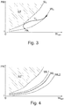
- An acceleration of the turbomachine impacts the margin vis-à-vis the pumping zone SZ, as illustrated in FIG. figure 3 .
- the figure 3 is essentially identical to the figure 2 , but it also presents the line of operation of the TL transient compressor during an acceleration from a stabilized operating point, said acceleration start point PA.
- the operating line (corresponding to the succession of effective operating points of the compressor) tends to approach the pumping line SL, which corresponds to a temporary loss of pumping margin.
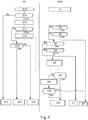
- the figure 4 illustrates on a graph similar to figures 2 and 3 the effect of a mechanical energy withdrawal and an air sampling on the operating points of a turbomachine compressor and the margin vis-à-vis the pumping zone.
- the figure 4 is essentially identical to the figure 2 , but it also has a compressor operating line when a mechanical energy sample is taken on the high pressure shaft WL1 and a compressor operating line when an air sample is made WL2.
- the air sampling has, as we see on the figure 4 , a positive effect on the pumping margin. Indeed, the operating line of the compressor when an air bleed is achieved WL2 is further away from the pump zone SZ than is the operating line WL of the compressor in the absence of any sampling (of energy or air).
- the mechanical energy sampling has, as we see on the figure 4 , a negative effect on the pumping margin. In fact, the operating line of the compressor when an energy withdrawal is made WL1 is closer to the pumping zone SZ than is the operating line WL of the compressor in the absence of any sampling (of energy or air).
- the invention tends to optimize the control of turbomachines vis-à-vis the pumping phenomenon, especially during their operation in transient and steady idle to avoid a definition of idle compared to extreme cases while ensuring no risk of pumping.
- the figure 5 illustrates the control of a turbomachine such as a gas turbine of an aircraft, in particular with regard to the management of pumping.
- Calculators (which can be separate or physically constituted by a single calculator) are used in the example of the figure 5 on the one hand for an energy management function, or energy manager said AEM for "Aircraft Energy Manager” and for an idle management function or Idle Manager says IM for "Idle Manager”.
- the idle manager IM is in charge of determining the speed of rotation of the turbomachine at idle.
- the energy manager AEM is in charge of managing sampling requirements, and how to satisfy them.
- a first step S1 the current requirements for taking mechanical energy and withdrawing air are determined.
- the operating point of the machine defined for example in a space such as that represented by the Figures 2 to 4 , is followed, continuously or periodically (at predetermined time intervals or in response to a event), and current (mechanical and air) sampling and current draw requirements are evaluated.
- step S2 it is evaluated whether the need for mechanical energy sampling corresponds to the current mechanical energy sampling. Inequality represents the change in an operating parameter that can bring the operating point closer to the pumping zone, or drive it into the pumping zone of the turbomachine (that is to say at least one compressor of the turbomachine). Similarly, it is evaluated in a step S3 whether the need for current air sampling corresponds to the current air sampling.
- step S4 If the response to these two tests is positive, the sampling requirements are satisfied, and no action is taken (step S4).
- Such an indicator can for example be activated in case of particular accelerating needs of the turbomachine or in the case of the selection of a so-called economic operating mode.
- the energy manager AEM also assesses whether the need for mechanical sampling could be reduced (step S6), and if both of these tests are positive, the energy manager AEM controls the reduction of the mechanical energy withdrawal (step S7).
- step S8 If the response to the two tests of steps S5 and S6 are not both positive, a request for authorization to modify the mechanical energy withdrawals is sent to a control system of the turbomachine (physically distinct or not from the aforementioned calculators). idle management and energy management) (step S8).
- a step S9 it is evaluated whether an authorization to modify the samples has been received by the energy manager AEM.
- This authorization issued by the control system of the turbomachine, is a necessary precondition for the modification of the samples applied to the turbomachine (with the exception of the case described below in which a maximum time has elapsed after which the modification of sampling is necessarily performed).
- step S10 If this authorization has been issued for the change of planned withdrawals, which means that the modification of the samples can be carried out on the current point of operation of the turbomachine without risking pumping, the change of mechanical energy sampling and / or air sampling is performed, that is to say that the current samples are aligned with the needs (step S10).
- a buffer is used to provide a part of the mechanical energy requirements (S11). The buffer is thus used until the authorization to modify the samples is issued or sufficient time ensuring that the turbine engine has reached an operating point allowing the application of the required samples without risk of pumping.
- One of the ideas developed in the invention thus consists in using the buffer for the supply of supplying energy to the consumers of the aircraft during the time necessary for the engine to adapt to power requirements, for example by increasing its power. idle level, if the pumping margin is reduced too much by a change in sampling requirements.
- the buffer naturally formed by the cabin of the aircraft (which can be chosen to renew the air more or less rapidly within a certain limit) can be used to temporarily increase the samples of air.
- a certain delay in the evolution of the function of air conditioning and / or renewal of the cabin air is acceptable, allowing to postpone a decrease in air intake for this function.
- the buffer is used while the turbine engine reaches an operating point allowing the modification of the samples without risk of pumping, even in case of rapid acceleration of the turbomachine. In other words, the use of the buffer is continued until the energy manager receives an authorization to modify the samples. Nevertheless, the use of the buffer can not be continued indefinitely and, in a step S12, the flow of a predefined maximum time is checked before modification of the samples.
- step S4 If this time is not reached, no action is performed (step S4). If this time is reached or exceeded, the sampling change is ordered, and the current draws are aligned with the needs (step S10).
- the turbomachine has been placed on an operating point ensuring sure any risk of pumping as described below. For this purpose, it is possible in practice to use two counters in parallel, the idle manager counter having a shorter duration than the energy manager counter, which ensures that the safe operating point is reached before evolution of samples.
- step S9 requires knowledge of the pumping margin for the current operating point.
- the pumping margin can be calculated, in parallel with the previously described sequence of steps, for example by the idle manager IM in a step of determining the margin S13, on the basis of the information gathered at the step S1 on the current operating point, current withdrawals, and sampling requirements.
- Step S13 and the following steps correspond to the steps carried out (in the exemplary embodiment shown) at the IM idle speed manager in order to interact with the energy manager AEM and, if necessary, to modify the idling speed. to increase the pumping margin.
- step S14 it is determined whether a request to change the samples has been issued (for example in step S8).
- step S15 If no request for change of the debits has been issued, no action is commanded and the idle is unchanged. If a request to change the samples has been issued, a counter is incremented (step S16), allowing the verification of the smooth running of the process.
- the turbomachine can be decelerated accordingly without implementing the steps described below.
- step S17 The pumping margin resulting from the application of the sampling change is then compared to a threshold, expressed for example in the form of a minimum margin (step S17). If the margin is greater than the predetermined threshold, a modification authorization is sent to the energy management computer in a step S18 (which, in the exemplary embodiment shown here, allows the realization of step S9 ).
- Step S20 the pumping margin on the current point of the turbomachine is sufficient to ensure a lack of pumping despite the required modification of the samples, and even if a sudden acceleration of the turbomachine was controlled.
- the turbomachine is brought to a default operating point, which corresponds to a predefined idle speed.
- This default point is said to be "safe" vis-à-vis the pumping phenomenon in that it allows both to ensure the need for maximum mechanical sampling, to allow a stop of air sampling, and to allow maximum acceleration of the turbomachine while ensuring the absence of pumping (step S21).
- This safe operating point with respect to pumping is also used if an error any is detected during the implementation of the method (for example during the determination of the pumping margin), or a temporary or permanent loss of communication between the energy manager and the control system of the turbomachine (for example with the idle manager), so as to guarantee the absence of pumping in case of uncertainty.
- Such a process can be completed by limiting the mechanical samples. This limitation can be achieved by stopping or limiting the power of components increasing the need for mechanical sampling.
- a hierarchical list of components or functions corresponding to components can be established and used (preferentially impacting first the components of little importance for the smooth running or comfort of the aircraft).
- Such a process can also be completed by a management of the air samples, for example by making it possible to maintain or increase the air samples in the transient operating phase of the turbomachine (taking advantage for example of the storage buffer air offered by the cabin of the aircraft, or by dedicated storage means), which increases the pumping margin.
- the figure 6 schematically shows a device for controlling a turbine engine T of an aircraft, according to one embodiment of the invention. Double arrows show a transfer of energy or air, and by simple arrows a transfer of data (information, instructions).
- the turbomachine T which can be of the type represented in FIG. figure 1 , comprises means for taking mechanical energy and air sampling means
- the device further comprises a BUF buffer.
- the buffer BUF allows the storage or the production of energy (without increasing the power of the turbomachine or generating additional thrust).
- energy production is meant, for example, the production of electrical energy by conversion of the chemical energy of kerosene, the buffer being able to be a generator.
- the BUF buffer may include a means for storing electrical energy (battery, supercapacitor / supercapacitor, etc.) or hydraulic energy (as a pressure accumulator) or mechanical (inertial storage, potential energy, etc., the buffer may include an auxiliary generator (generally referred to by the acronym acronym "APU") which is generally used on the ground by the aircraft to generate electricity.
- APU auxiliary generator
- the device also includes an energy manager AEM and an idle manager IM.
- the AEM energy manager notably has the function of controlling the samples taken on the turbomachine.
- the idle manager IM is an element of a control system of the turbomachine T, which drives and tracks the operating point
- the control system of the turbomachine for example via the IM idle manager also makes it possible to follow the pumping margin, ie the margin with respect to an SZ pumping zone.
- the energy manager AEM and the idle manager IM communicate in order to authorize or not the modification of the samples on the turbomachine.
- This communication corresponds to the implementation of a protocol P, which may for example be the protocol represented in FIG. figure 5 .
- this modification can be authorized after ensuring that the turbine engine is at an operating point ensuring the absence of pumping. If the current operating point of the turbomachine does not allow the required modification of the samples, the turbomachine its idle speed is increased.
- at least a part of the mechanical energy harvesting needs of EC energy consumer elements generally supplied by the only mechanical energy samples are provided by the BUF buffer.
- the invention thus developed allows an optimization of the operation of a turbomachine for the propulsion of an aircraft, thanks to the use of a communication protocol between an energy manager and an idle manager (or more generally a control system of a turbomachine of an aircraft.
- This communication makes it possible to prevent a modification of the samplings on the turbomachine as long as it is not on an operating point guaranteeing the absence of pumping despite the modification of the samples (and a possible rapid acceleration of the turbomachine).
- a buffer storage or energy generator
- the use of the buffer makes it possible to temporarily satisfy all or part of the energy requirements generally fully satisfied by the mechanical energy withdrawal at the turbomachine.
- the samples are considered globally, including the air samples, which are beneficial for the pumping margin.
Landscapes
- Engineering & Computer Science (AREA)
- Chemical & Material Sciences (AREA)
- Combustion & Propulsion (AREA)
- Mechanical Engineering (AREA)
- General Engineering & Computer Science (AREA)
- Physics & Mathematics (AREA)
- Fluid Mechanics (AREA)
- Life Sciences & Earth Sciences (AREA)
- Sustainable Development (AREA)
- Control Of Turbines (AREA)
Applications Claiming Priority (1)
| Application Number | Priority Date | Filing Date | Title |
|---|---|---|---|
| FR1661991A FR3059734A1 (fr) | 2016-12-06 | 2016-12-06 | Procede et dispositif de controle des prelevements sur une turbomachine limitant le risque de pompage par echange d'informations entre un gestionnaire d'energie et un systeme de controle de la turbomachine |
Publications (2)
| Publication Number | Publication Date |
|---|---|
| EP3333393A1 true EP3333393A1 (de) | 2018-06-13 |
| EP3333393B1 EP3333393B1 (de) | 2020-04-08 |
Family
ID=58609485
Family Applications (1)
| Application Number | Title | Priority Date | Filing Date |
|---|---|---|---|
| EP17205590.7A Active EP3333393B1 (de) | 2016-12-06 | 2017-12-06 | Verfahren und vorrichtung zur kontrolle der entnahmen aus einer turbomaschine zur begrenzung des pumprisikos durch informationsaustausch zwischen einem energiemanager und einem regelungssystem der turbomaschine |
Country Status (4)
| Country | Link |
|---|---|
| US (1) | US10677251B2 (de) |
| EP (1) | EP3333393B1 (de) |
| CN (1) | CN108150293B (de) |
| FR (1) | FR3059734A1 (de) |
Families Citing this family (4)
| Publication number | Priority date | Publication date | Assignee | Title |
|---|---|---|---|---|
| CN109184919A (zh) * | 2018-10-08 | 2019-01-11 | 南京航空航天大学 | 一种基于航空发动机失稳预测的主动防喘控制方法 |
| FR3099526B1 (fr) | 2019-07-29 | 2021-08-20 | Airbus | Procédé et système de contrôle de régime de ralenti et de prélèvement de puissance produite par un moteur d’aéronef. |
| US11739699B2 (en) * | 2021-11-08 | 2023-08-29 | Pratt & Whitney Canada Corp. | Method of controlling the geometrical configuration of a variable geometry element in a gas turbine engine compressor stage |
| FR3129378A1 (fr) * | 2021-11-22 | 2023-05-26 | Airbus (S.A.S.) | Procédé de gestion des quantités de puissance prélevées sur des unités de puissance des ensembles de propulsion d’un aéronef |
Citations (6)
| Publication number | Priority date | Publication date | Assignee | Title |
|---|---|---|---|---|
| US4606191A (en) * | 1985-07-16 | 1986-08-19 | Rolls-Royce Limited | Control systems for gas turbine aeroengines |
| EP0980980A2 (de) * | 1998-08-18 | 2000-02-23 | United Technologies Corporation | Steuerungssystem zum Modulieren der Luftentnahme in Abhängigkeit der Abnutzung des Triebwerks |
| US8459038B1 (en) * | 2012-02-09 | 2013-06-11 | Williams International Co., L.L.C. | Two-spool turboshaft engine control system and method |
| US20140297155A1 (en) | 2012-07-12 | 2014-10-02 | Pratt & Whitney Canada Corp. | Aircraft power outtake management |
| EP2955334A1 (de) * | 2014-06-09 | 2015-12-16 | Rolls-Royce plc | Verfahren und vorrichtung zur steuerung eines verdichters eines gasturbinenmotors |
| WO2016020618A1 (fr) * | 2014-08-08 | 2016-02-11 | Snecma | Hybridation des compresseurs d'un turboréacteur |
Family Cites Families (11)
| Publication number | Priority date | Publication date | Assignee | Title |
|---|---|---|---|---|
| US5165844A (en) * | 1991-11-08 | 1992-11-24 | United Technologies Corporation | On-line stall margin adjustment in a gas turbine engine |
| US5222356A (en) * | 1991-12-12 | 1993-06-29 | Allied-Signal Inc. | Modulating surge prevention control for a variable geometry diffuser |
| US5313778A (en) * | 1992-12-10 | 1994-05-24 | United Technologies Corporation | Automatic turbine engine bleed valve control for enhanced fuel management |
| GB2273316B (en) * | 1992-12-12 | 1996-02-28 | Rolls Royce Plc | Bleed valve control |
| WO2003044353A1 (en) * | 2001-11-15 | 2003-05-30 | Goodrich Pump & Engine Control Systems, Inc. | Method and apparatus for adaptive acceleration schedules in gas turbine engine control systems |
| US8322145B2 (en) * | 2009-04-23 | 2012-12-04 | General Electric Company | Systems and methods for providing surge protection to a turbine component |
| CN102042092B (zh) * | 2010-12-06 | 2013-05-29 | 哈尔滨工业大学 | 一种涡轮增压系统压气机风量切换控制的喘振保护方法 |
| US20130327014A1 (en) * | 2012-06-12 | 2013-12-12 | Djamal Moulebhar | Devices and Methods to Optimize Aircraft Power Plant and Aircraft Operations |
| RU2563445C2 (ru) * | 2012-07-13 | 2015-09-20 | Альстом Текнолоджи Лтд | Способ и устройство для регулирования помпажа газотурбинного двигателя |
| ITFI20130063A1 (it) * | 2013-03-26 | 2014-09-27 | Nuovo Pignone Srl | "methods and systems for antisurge control of turbo compressors with side stream" |
| CN204186477U (zh) * | 2014-10-13 | 2015-03-04 | 深圳大唐宝昌燃气发电有限公司 | 一种燃气轮机防喘放气系统 |
-
2016
- 2016-12-06 FR FR1661991A patent/FR3059734A1/fr not_active Ceased
-
2017
- 2017-12-05 CN CN201711266438.4A patent/CN108150293B/zh active Active
- 2017-12-05 US US15/831,643 patent/US10677251B2/en active Active
- 2017-12-06 EP EP17205590.7A patent/EP3333393B1/de active Active
Patent Citations (6)
| Publication number | Priority date | Publication date | Assignee | Title |
|---|---|---|---|---|
| US4606191A (en) * | 1985-07-16 | 1986-08-19 | Rolls-Royce Limited | Control systems for gas turbine aeroengines |
| EP0980980A2 (de) * | 1998-08-18 | 2000-02-23 | United Technologies Corporation | Steuerungssystem zum Modulieren der Luftentnahme in Abhängigkeit der Abnutzung des Triebwerks |
| US8459038B1 (en) * | 2012-02-09 | 2013-06-11 | Williams International Co., L.L.C. | Two-spool turboshaft engine control system and method |
| US20140297155A1 (en) | 2012-07-12 | 2014-10-02 | Pratt & Whitney Canada Corp. | Aircraft power outtake management |
| EP2955334A1 (de) * | 2014-06-09 | 2015-12-16 | Rolls-Royce plc | Verfahren und vorrichtung zur steuerung eines verdichters eines gasturbinenmotors |
| WO2016020618A1 (fr) * | 2014-08-08 | 2016-02-11 | Snecma | Hybridation des compresseurs d'un turboréacteur |
Also Published As
| Publication number | Publication date |
|---|---|
| FR3059734A1 (fr) | 2018-06-08 |
| CN108150293B (zh) | 2022-01-07 |
| US10677251B2 (en) | 2020-06-09 |
| CN108150293A (zh) | 2018-06-12 |
| US20180163734A1 (en) | 2018-06-14 |
| EP3333393B1 (de) | 2020-04-08 |
Similar Documents
| Publication | Publication Date | Title |
|---|---|---|
| EP2893169B1 (de) | Verfahren und system zum starten eines flugzeugsturbotriebwerks | |
| EP3224141B1 (de) | Antriebseinheit mit mitteln zu selektiven kopplung | |
| EP3186489B1 (de) | Vorrichtung und verfahren zum starten einer gasturbine, verfahren zur regelung der drehzahl einer gasturbine und zugehörige gasturbine und turbinenmotor | |
| EP2609311B1 (de) | Verfahren zur optimierung des motorantriebeinsatzes eines flugzeugs und diesbezügliche autonome motorbaugruppe | |
| EP3208429B1 (de) | System und verfahren zum starten eines zweimotorigen luftfahrzeugs | |
| CA2764719C (fr) | Procede de realisation d'un test de la chaine de protection d'une turbomachine contre les survitesses lors d'un demarrage | |
| EP3333393B1 (de) | Verfahren und vorrichtung zur kontrolle der entnahmen aus einer turbomaschine zur begrenzung des pumprisikos durch informationsaustausch zwischen einem energiemanager und einem regelungssystem der turbomaschine | |
| EP2864616B1 (de) | Verfahren zur einstellung eines referenzwerts eines parameters zur beeinflussung des schubs eines gasturbinentriebwerks | |
| EP3660276B1 (de) | Verfahren und system zum abschalten einer gasturbine und fahrzeug | |
| FR3007461A1 (fr) | Procede et systeme de demarrage d'une turbomachine d'aeronef. | |
| WO2014174207A1 (fr) | Dispositif de delestage des alternateurs d'une turbomachine pendant ses accelerations | |
| EP3149313B1 (de) | Verfahren und vorrichtung zur steuerung einer schubkraft eines strahltriebwerks | |
| EP3959427B1 (de) | Verfahren zur regelung einer turbomaschine mit einer temporären leistungserhöhungsvorrichtung | |
| FR2986570A1 (fr) | Dispositif et procede de regulation d'une installation motrice comportant au moins un turbomoteur, et aeronef | |
| WO2021018524A1 (fr) | Procédé et système de contrôle de régime de ralenti et de prélèvement de puissance produite par un moteur d'aéronef | |
| EP4045770B1 (de) | Verfahren zum schnellen anhalten eines rotors eines hubschraubers nach der landung | |
| EP1591645A1 (de) | Verfahren und Anordnung zur Regulierung des Brennstoffmengenstromes einer Turbomaschine | |
| FR3028887B1 (fr) | Procede et circuit de lubrification pour une turbomachine utilisant des moyens electriques | |
| FR3031139A1 (fr) | Procede de regulation de la temperature d'huile de lubrification d'un moteur | |
| FR2947300A1 (fr) | Procede de realisation d'un test de la chaine de protection d'une turbomachine contre les survitesses lors d'un demarrage. | |
| WO2025011898A1 (fr) | Procede de commande d'un systeme propulsif d'aeronef ayant des turbomoteurs fonctionnant en parallele et susceptibles d'etre places en veille et aeronef correspondant |
Legal Events
| Date | Code | Title | Description |
|---|---|---|---|
| PUAI | Public reference made under article 153(3) epc to a published international application that has entered the european phase |
Free format text: ORIGINAL CODE: 0009012 |
|
| STAA | Information on the status of an ep patent application or granted ep patent |
Free format text: STATUS: THE APPLICATION HAS BEEN PUBLISHED |
|
| AK | Designated contracting states |
Kind code of ref document: A1 Designated state(s): AL AT BE BG CH CY CZ DE DK EE ES FI FR GB GR HR HU IE IS IT LI LT LU LV MC MK MT NL NO PL PT RO RS SE SI SK SM TR |
|
| AX | Request for extension of the european patent |
Extension state: BA ME |
|
| STAA | Information on the status of an ep patent application or granted ep patent |
Free format text: STATUS: REQUEST FOR EXAMINATION WAS MADE |
|
| 17P | Request for examination filed |
Effective date: 20181115 |
|
| RBV | Designated contracting states (corrected) |
Designated state(s): AL AT BE BG CH CY CZ DE DK EE ES FI FR GB GR HR HU IE IS IT LI LT LU LV MC MK MT NL NO PL PT RO RS SE SI SK SM TR |
|
| STAA | Information on the status of an ep patent application or granted ep patent |
Free format text: STATUS: EXAMINATION IS IN PROGRESS |
|
| 17Q | First examination report despatched |
Effective date: 20190321 |
|
| GRAP | Despatch of communication of intention to grant a patent |
Free format text: ORIGINAL CODE: EPIDOSNIGR1 |
|
| STAA | Information on the status of an ep patent application or granted ep patent |
Free format text: STATUS: GRANT OF PATENT IS INTENDED |
|
| INTG | Intention to grant announced |
Effective date: 20200109 |
|
| GRAS | Grant fee paid |
Free format text: ORIGINAL CODE: EPIDOSNIGR3 |
|
| GRAA | (expected) grant |
Free format text: ORIGINAL CODE: 0009210 |
|
| STAA | Information on the status of an ep patent application or granted ep patent |
Free format text: STATUS: THE PATENT HAS BEEN GRANTED |
|
| AK | Designated contracting states |
Kind code of ref document: B1 Designated state(s): AL AT BE BG CH CY CZ DE DK EE ES FI FR GB GR HR HU IE IS IT LI LT LU LV MC MK MT NL NO PL PT RO RS SE SI SK SM TR |
|
| REG | Reference to a national code |
Ref country code: AT Ref legal event code: REF Ref document number: 1254696 Country of ref document: AT Kind code of ref document: T Effective date: 20200415 Ref country code: CH Ref legal event code: EP |
|
| REG | Reference to a national code |
Ref country code: DE Ref legal event code: R096 Ref document number: 602017014319 Country of ref document: DE |
|
| REG | Reference to a national code |
Ref country code: IE Ref legal event code: FG4D Free format text: LANGUAGE OF EP DOCUMENT: FRENCH |
|
| REG | Reference to a national code |
Ref country code: NL Ref legal event code: MP Effective date: 20200408 |
|
| REG | Reference to a national code |
Ref country code: LT Ref legal event code: MG4D |
|
| PG25 | Lapsed in a contracting state [announced via postgrant information from national office to epo] |
Ref country code: PT Free format text: LAPSE BECAUSE OF FAILURE TO SUBMIT A TRANSLATION OF THE DESCRIPTION OR TO PAY THE FEE WITHIN THE PRESCRIBED TIME-LIMIT Effective date: 20200817 Ref country code: LT Free format text: LAPSE BECAUSE OF FAILURE TO SUBMIT A TRANSLATION OF THE DESCRIPTION OR TO PAY THE FEE WITHIN THE PRESCRIBED TIME-LIMIT Effective date: 20200408 Ref country code: GR Free format text: LAPSE BECAUSE OF FAILURE TO SUBMIT A TRANSLATION OF THE DESCRIPTION OR TO PAY THE FEE WITHIN THE PRESCRIBED TIME-LIMIT Effective date: 20200709 Ref country code: IS Free format text: LAPSE BECAUSE OF FAILURE TO SUBMIT A TRANSLATION OF THE DESCRIPTION OR TO PAY THE FEE WITHIN THE PRESCRIBED TIME-LIMIT Effective date: 20200808 Ref country code: NO Free format text: LAPSE BECAUSE OF FAILURE TO SUBMIT A TRANSLATION OF THE DESCRIPTION OR TO PAY THE FEE WITHIN THE PRESCRIBED TIME-LIMIT Effective date: 20200708 Ref country code: FI Free format text: LAPSE BECAUSE OF FAILURE TO SUBMIT A TRANSLATION OF THE DESCRIPTION OR TO PAY THE FEE WITHIN THE PRESCRIBED TIME-LIMIT Effective date: 20200408 Ref country code: SE Free format text: LAPSE BECAUSE OF FAILURE TO SUBMIT A TRANSLATION OF THE DESCRIPTION OR TO PAY THE FEE WITHIN THE PRESCRIBED TIME-LIMIT Effective date: 20200408 Ref country code: NL Free format text: LAPSE BECAUSE OF FAILURE TO SUBMIT A TRANSLATION OF THE DESCRIPTION OR TO PAY THE FEE WITHIN THE PRESCRIBED TIME-LIMIT Effective date: 20200408 |
|
| REG | Reference to a national code |
Ref country code: AT Ref legal event code: MK05 Ref document number: 1254696 Country of ref document: AT Kind code of ref document: T Effective date: 20200408 |
|
| PG25 | Lapsed in a contracting state [announced via postgrant information from national office to epo] |
Ref country code: HR Free format text: LAPSE BECAUSE OF FAILURE TO SUBMIT A TRANSLATION OF THE DESCRIPTION OR TO PAY THE FEE WITHIN THE PRESCRIBED TIME-LIMIT Effective date: 20200408 Ref country code: BG Free format text: LAPSE BECAUSE OF FAILURE TO SUBMIT A TRANSLATION OF THE DESCRIPTION OR TO PAY THE FEE WITHIN THE PRESCRIBED TIME-LIMIT Effective date: 20200708 Ref country code: RS Free format text: LAPSE BECAUSE OF FAILURE TO SUBMIT A TRANSLATION OF THE DESCRIPTION OR TO PAY THE FEE WITHIN THE PRESCRIBED TIME-LIMIT Effective date: 20200408 Ref country code: LV Free format text: LAPSE BECAUSE OF FAILURE TO SUBMIT A TRANSLATION OF THE DESCRIPTION OR TO PAY THE FEE WITHIN THE PRESCRIBED TIME-LIMIT Effective date: 20200408 |
|
| PG25 | Lapsed in a contracting state [announced via postgrant information from national office to epo] |
Ref country code: AL Free format text: LAPSE BECAUSE OF FAILURE TO SUBMIT A TRANSLATION OF THE DESCRIPTION OR TO PAY THE FEE WITHIN THE PRESCRIBED TIME-LIMIT Effective date: 20200408 |
|
| REG | Reference to a national code |
Ref country code: DE Ref legal event code: R097 Ref document number: 602017014319 Country of ref document: DE |
|
| PG25 | Lapsed in a contracting state [announced via postgrant information from national office to epo] |
Ref country code: ES Free format text: LAPSE BECAUSE OF FAILURE TO SUBMIT A TRANSLATION OF THE DESCRIPTION OR TO PAY THE FEE WITHIN THE PRESCRIBED TIME-LIMIT Effective date: 20200408 Ref country code: DK Free format text: LAPSE BECAUSE OF FAILURE TO SUBMIT A TRANSLATION OF THE DESCRIPTION OR TO PAY THE FEE WITHIN THE PRESCRIBED TIME-LIMIT Effective date: 20200408 Ref country code: AT Free format text: LAPSE BECAUSE OF FAILURE TO SUBMIT A TRANSLATION OF THE DESCRIPTION OR TO PAY THE FEE WITHIN THE PRESCRIBED TIME-LIMIT Effective date: 20200408 Ref country code: SM Free format text: LAPSE BECAUSE OF FAILURE TO SUBMIT A TRANSLATION OF THE DESCRIPTION OR TO PAY THE FEE WITHIN THE PRESCRIBED TIME-LIMIT Effective date: 20200408 Ref country code: IT Free format text: LAPSE BECAUSE OF FAILURE TO SUBMIT A TRANSLATION OF THE DESCRIPTION OR TO PAY THE FEE WITHIN THE PRESCRIBED TIME-LIMIT Effective date: 20200408 Ref country code: EE Free format text: LAPSE BECAUSE OF FAILURE TO SUBMIT A TRANSLATION OF THE DESCRIPTION OR TO PAY THE FEE WITHIN THE PRESCRIBED TIME-LIMIT Effective date: 20200408 Ref country code: CZ Free format text: LAPSE BECAUSE OF FAILURE TO SUBMIT A TRANSLATION OF THE DESCRIPTION OR TO PAY THE FEE WITHIN THE PRESCRIBED TIME-LIMIT Effective date: 20200408 Ref country code: RO Free format text: LAPSE BECAUSE OF FAILURE TO SUBMIT A TRANSLATION OF THE DESCRIPTION OR TO PAY THE FEE WITHIN THE PRESCRIBED TIME-LIMIT Effective date: 20200408 |
|
| PLBE | No opposition filed within time limit |
Free format text: ORIGINAL CODE: 0009261 |
|
| STAA | Information on the status of an ep patent application or granted ep patent |
Free format text: STATUS: NO OPPOSITION FILED WITHIN TIME LIMIT |
|
| PG25 | Lapsed in a contracting state [announced via postgrant information from national office to epo] |
Ref country code: PL Free format text: LAPSE BECAUSE OF FAILURE TO SUBMIT A TRANSLATION OF THE DESCRIPTION OR TO PAY THE FEE WITHIN THE PRESCRIBED TIME-LIMIT Effective date: 20200408 Ref country code: SK Free format text: LAPSE BECAUSE OF FAILURE TO SUBMIT A TRANSLATION OF THE DESCRIPTION OR TO PAY THE FEE WITHIN THE PRESCRIBED TIME-LIMIT Effective date: 20200408 |
|
| 26N | No opposition filed |
Effective date: 20210112 |
|
| PG25 | Lapsed in a contracting state [announced via postgrant information from national office to epo] |
Ref country code: SI Free format text: LAPSE BECAUSE OF FAILURE TO SUBMIT A TRANSLATION OF THE DESCRIPTION OR TO PAY THE FEE WITHIN THE PRESCRIBED TIME-LIMIT Effective date: 20200408 |
|
| REG | Reference to a national code |
Ref country code: CH Ref legal event code: PL |
|
| PG25 | Lapsed in a contracting state [announced via postgrant information from national office to epo] |
Ref country code: MC Free format text: LAPSE BECAUSE OF FAILURE TO SUBMIT A TRANSLATION OF THE DESCRIPTION OR TO PAY THE FEE WITHIN THE PRESCRIBED TIME-LIMIT Effective date: 20200408 |
|
| REG | Reference to a national code |
Ref country code: BE Ref legal event code: MM Effective date: 20201231 |
|
| PG25 | Lapsed in a contracting state [announced via postgrant information from national office to epo] |
Ref country code: IE Free format text: LAPSE BECAUSE OF NON-PAYMENT OF DUE FEES Effective date: 20201206 Ref country code: LU Free format text: LAPSE BECAUSE OF NON-PAYMENT OF DUE FEES Effective date: 20201206 |
|
| PG25 | Lapsed in a contracting state [announced via postgrant information from national office to epo] |
Ref country code: CH Free format text: LAPSE BECAUSE OF NON-PAYMENT OF DUE FEES Effective date: 20201231 Ref country code: LI Free format text: LAPSE BECAUSE OF NON-PAYMENT OF DUE FEES Effective date: 20201231 |
|
| PG25 | Lapsed in a contracting state [announced via postgrant information from national office to epo] |
Ref country code: TR Free format text: LAPSE BECAUSE OF FAILURE TO SUBMIT A TRANSLATION OF THE DESCRIPTION OR TO PAY THE FEE WITHIN THE PRESCRIBED TIME-LIMIT Effective date: 20200408 Ref country code: MT Free format text: LAPSE BECAUSE OF FAILURE TO SUBMIT A TRANSLATION OF THE DESCRIPTION OR TO PAY THE FEE WITHIN THE PRESCRIBED TIME-LIMIT Effective date: 20200408 Ref country code: CY Free format text: LAPSE BECAUSE OF FAILURE TO SUBMIT A TRANSLATION OF THE DESCRIPTION OR TO PAY THE FEE WITHIN THE PRESCRIBED TIME-LIMIT Effective date: 20200408 |
|
| PG25 | Lapsed in a contracting state [announced via postgrant information from national office to epo] |
Ref country code: MK Free format text: LAPSE BECAUSE OF FAILURE TO SUBMIT A TRANSLATION OF THE DESCRIPTION OR TO PAY THE FEE WITHIN THE PRESCRIBED TIME-LIMIT Effective date: 20200408 |
|
| PG25 | Lapsed in a contracting state [announced via postgrant information from national office to epo] |
Ref country code: BE Free format text: LAPSE BECAUSE OF NON-PAYMENT OF DUE FEES Effective date: 20201231 |
|
| PGFP | Annual fee paid to national office [announced via postgrant information from national office to epo] |
Ref country code: DE Payment date: 20251211 Year of fee payment: 9 |
|
| PGFP | Annual fee paid to national office [announced via postgrant information from national office to epo] |
Ref country code: GB Payment date: 20251219 Year of fee payment: 9 |
|
| PGFP | Annual fee paid to national office [announced via postgrant information from national office to epo] |
Ref country code: FR Payment date: 20251229 Year of fee payment: 9 |