EP3333120A1 - Industrial vehicle - Google Patents
Industrial vehicle Download PDFInfo
- Publication number
- EP3333120A1 EP3333120A1 EP17204343.2A EP17204343A EP3333120A1 EP 3333120 A1 EP3333120 A1 EP 3333120A1 EP 17204343 A EP17204343 A EP 17204343A EP 3333120 A1 EP3333120 A1 EP 3333120A1
- Authority
- EP
- European Patent Office
- Prior art keywords
- lateral acceleration
- vehicle
- industrial vehicle
- threshold value
- turned
- Prior art date
- Legal status (The legal status is an assumption and is not a legal conclusion. Google has not performed a legal analysis and makes no representation as to the accuracy of the status listed.)
- Granted
Links
- 230000001133 acceleration Effects 0.000 claims abstract description 97
- 238000000034 method Methods 0.000 description 13
- 238000011084 recovery Methods 0.000 description 8
- 230000007423 decrease Effects 0.000 description 3
- 230000002123 temporal effect Effects 0.000 description 3
- 230000003247 decreasing effect Effects 0.000 description 2
- 238000001514 detection method Methods 0.000 description 2
- 230000009977 dual effect Effects 0.000 description 1
- 230000005484 gravity Effects 0.000 description 1
- 230000000717 retained effect Effects 0.000 description 1
- 238000005096 rolling process Methods 0.000 description 1
Images


Classifications
-
- B—PERFORMING OPERATIONS; TRANSPORTING
- B66—HOISTING; LIFTING; HAULING
- B66F—HOISTING, LIFTING, HAULING OR PUSHING, NOT OTHERWISE PROVIDED FOR, e.g. DEVICES WHICH APPLY A LIFTING OR PUSHING FORCE DIRECTLY TO THE SURFACE OF A LOAD
- B66F9/00—Devices for lifting or lowering bulky or heavy goods for loading or unloading purposes
- B66F9/06—Devices for lifting or lowering bulky or heavy goods for loading or unloading purposes movable, with their loads, on wheels or the like, e.g. fork-lift trucks
- B66F9/075—Constructional features or details
- B66F9/20—Means for actuating or controlling masts, platforms, or forks
- B66F9/24—Electrical devices or systems
-
- B—PERFORMING OPERATIONS; TRANSPORTING
- B60—VEHICLES IN GENERAL
- B60G—VEHICLE SUSPENSION ARRANGEMENTS
- B60G17/00—Resilient suspensions having means for adjusting the spring or vibration-damper characteristics, for regulating the distance between a supporting surface and a sprung part of vehicle or for locking suspension during use to meet varying vehicular or surface conditions, e.g. due to speed or load
- B60G17/005—Suspension locking arrangements
-
- B—PERFORMING OPERATIONS; TRANSPORTING
- B66—HOISTING; LIFTING; HAULING
- B66F—HOISTING, LIFTING, HAULING OR PUSHING, NOT OTHERWISE PROVIDED FOR, e.g. DEVICES WHICH APPLY A LIFTING OR PUSHING FORCE DIRECTLY TO THE SURFACE OF A LOAD
- B66F9/00—Devices for lifting or lowering bulky or heavy goods for loading or unloading purposes
- B66F9/06—Devices for lifting or lowering bulky or heavy goods for loading or unloading purposes movable, with their loads, on wheels or the like, e.g. fork-lift trucks
- B66F9/075—Constructional features or details
-
- B—PERFORMING OPERATIONS; TRANSPORTING
- B60—VEHICLES IN GENERAL
- B60G—VEHICLE SUSPENSION ARRANGEMENTS
- B60G17/00—Resilient suspensions having means for adjusting the spring or vibration-damper characteristics, for regulating the distance between a supporting surface and a sprung part of vehicle or for locking suspension during use to meet varying vehicular or surface conditions, e.g. due to speed or load
- B60G17/015—Resilient suspensions having means for adjusting the spring or vibration-damper characteristics, for regulating the distance between a supporting surface and a sprung part of vehicle or for locking suspension during use to meet varying vehicular or surface conditions, e.g. due to speed or load the regulating means comprising electric or electronic elements
- B60G17/016—Resilient suspensions having means for adjusting the spring or vibration-damper characteristics, for regulating the distance between a supporting surface and a sprung part of vehicle or for locking suspension during use to meet varying vehicular or surface conditions, e.g. due to speed or load the regulating means comprising electric or electronic elements characterised by their responsiveness, when the vehicle is travelling, to specific motion, a specific condition, or driver input
- B60G17/0162—Resilient suspensions having means for adjusting the spring or vibration-damper characteristics, for regulating the distance between a supporting surface and a sprung part of vehicle or for locking suspension during use to meet varying vehicular or surface conditions, e.g. due to speed or load the regulating means comprising electric or electronic elements characterised by their responsiveness, when the vehicle is travelling, to specific motion, a specific condition, or driver input mainly during a motion involving steering operation, e.g. cornering, overtaking
-
- B—PERFORMING OPERATIONS; TRANSPORTING
- B66—HOISTING; LIFTING; HAULING
- B66F—HOISTING, LIFTING, HAULING OR PUSHING, NOT OTHERWISE PROVIDED FOR, e.g. DEVICES WHICH APPLY A LIFTING OR PUSHING FORCE DIRECTLY TO THE SURFACE OF A LOAD
- B66F17/00—Safety devices, e.g. for limiting or indicating lifting force
- B66F17/003—Safety devices, e.g. for limiting or indicating lifting force for fork-lift trucks
-
- B—PERFORMING OPERATIONS; TRANSPORTING
- B66—HOISTING; LIFTING; HAULING
- B66F—HOISTING, LIFTING, HAULING OR PUSHING, NOT OTHERWISE PROVIDED FOR, e.g. DEVICES WHICH APPLY A LIFTING OR PUSHING FORCE DIRECTLY TO THE SURFACE OF A LOAD
- B66F9/00—Devices for lifting or lowering bulky or heavy goods for loading or unloading purposes
- B66F9/06—Devices for lifting or lowering bulky or heavy goods for loading or unloading purposes movable, with their loads, on wheels or the like, e.g. fork-lift trucks
- B66F9/075—Constructional features or details
- B66F9/07586—Suspension or mounting of wheels on chassis
-
- B—PERFORMING OPERATIONS; TRANSPORTING
- B60—VEHICLES IN GENERAL
- B60G—VEHICLE SUSPENSION ARRANGEMENTS
- B60G2200/00—Indexing codes relating to suspension types
- B60G2200/30—Rigid axle suspensions
- B60G2200/32—Rigid axle suspensions pivoted
- B60G2200/322—Rigid axle suspensions pivoted with a single pivot point and a straight axle
-
- B—PERFORMING OPERATIONS; TRANSPORTING
- B60—VEHICLES IN GENERAL
- B60G—VEHICLE SUSPENSION ARRANGEMENTS
- B60G2204/00—Indexing codes related to suspensions per se or to auxiliary parts
- B60G2204/40—Auxiliary suspension parts; Adjustment of suspensions
- B60G2204/46—Means for locking the suspension
- B60G2204/4605—Means for locking the suspension hydraulically, e.g. interrupting communication between the chambers of a hydraulic cylinder
-
- B—PERFORMING OPERATIONS; TRANSPORTING
- B60—VEHICLES IN GENERAL
- B60G—VEHICLE SUSPENSION ARRANGEMENTS
- B60G2300/00—Indexing codes relating to the type of vehicle
- B60G2300/02—Trucks; Load vehicles
- B60G2300/022—Fork lift trucks, Clark
-
- B—PERFORMING OPERATIONS; TRANSPORTING
- B60—VEHICLES IN GENERAL
- B60G—VEHICLE SUSPENSION ARRANGEMENTS
- B60G2400/00—Indexing codes relating to detected, measured or calculated conditions or factors
- B60G2400/05—Attitude
- B60G2400/052—Angular rate
- B60G2400/0523—Yaw rate
-
- B—PERFORMING OPERATIONS; TRANSPORTING
- B60—VEHICLES IN GENERAL
- B60G—VEHICLE SUSPENSION ARRANGEMENTS
- B60G2400/00—Indexing codes relating to detected, measured or calculated conditions or factors
- B60G2400/20—Speed
- B60G2400/204—Vehicle speed
-
- B—PERFORMING OPERATIONS; TRANSPORTING
- B60—VEHICLES IN GENERAL
- B60G—VEHICLE SUSPENSION ARRANGEMENTS
- B60G2400/00—Indexing codes relating to detected, measured or calculated conditions or factors
- B60G2400/90—Other conditions or factors
- B60G2400/95—Position of vehicle body elements
-
- B—PERFORMING OPERATIONS; TRANSPORTING
- B60—VEHICLES IN GENERAL
- B60G—VEHICLE SUSPENSION ARRANGEMENTS
- B60G2800/00—Indexing codes relating to the type of movement or to the condition of the vehicle and to the end result to be achieved by the control action
- B60G2800/01—Attitude or posture control
- B60G2800/012—Rolling condition
- B60G2800/0124—Roll-over conditions
Definitions
- the present invention relates to an industrial vehicle such as a forklift truck.
- Japanese Patent No. 3129259 discloses an industrial vehicle in which an axle is pivotally supported by the vehicle body and the pivotal motion of the axle may be restricted.
- the pivoting of the axle of the vehicle is temporarily restricted while the vehicle is being turned by steering according to a limit value set for the yaw acceleration occurring when the vehicle is turned, so that the industrial vehicle can restrict the tilting of the body thereby to allow the vehicle to travel stably.
- Japanese Patent Application Publication No. 2005-96894 discloses an industrial vehicle is operable to select either of the limit mode in which the vehicle traveling speed is limited based on the condition of turning of the vehicle and the gravity center height of the vehicle and the non-limit mode in which the vehicle traveling speed is not limited.
- control interference in a vehicle having an electromagnetic solenoid which is used as an actuator for temporally restricting the pivoting of the axle while the vehicle is being turned, an operator of the vehicle may experience an uncomfortable feel due to a time lag ⁇ of the actuator as shown in FIGS. 9A through 9D , that is, due to the time lag ⁇ occurring between the time when command signal is generated and the time when the restriction of the pivoting motion of the axle and the vehicle speed limiting are actually effected. The operator of the vehicle feels that this time lag ⁇ is uncomfortable.
- the present invention is directed to providing an industrial vehicle that can be turned smoothly and stably so as to free an operator of the vehicle from uncomfortable feel when the industrial vehicle is turned.
- an industrial vehicle includes a body, an axle pivotally supported by the body, a lateral acceleration sensor determining lateral acceleration applied to the body when the industrial vehicle is turned, an actuator temporally restricting pivoting of the axle while the industrial vehicle is being turned, a vehicle speed limiter limiting vehicle traveling speed when the industrial vehicle is turned, and a controller driving the actuator based on the lateral acceleration determined by the lateral acceleration sensor to temporally restrict pivoting of the axle while the industrial vehicle is being turned and to limit traveling speed of the industrial vehicle by the vehicle speed limiter based on the lateral acceleration measured by the lateral acceleration sensor when the industrial vehicle is turned.
- a first lateral acceleration threshold value which is used in judging whether traveling speed of the industrial vehicle should be limited is set smaller than a second lateral acceleration threshold value which is used in judging whether pivoting of the axle should be temporally restricted.
- an upper limit value is set in deceleration in limiting traveling speed of the industrial vehicle.
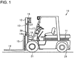
- the forklift truck which is designated generally by reference numeral 10 is a front drive, rear steering, four-wheel vehicle.
- the forklift truck 10 includes a body 11 and an outer mast 12 the lower end of which is mounted to the front of the body 11 and that is tiltable toward the front and the rear.
- the outer mast 12 supports inner masts 13 such that the inner masts 13 can be elevated and lowered.
- the inner masts 13 support a lift bracket 15, to which forks 14 are fixed, such that the lift bracket 15 can be elevated and lowered.
- a sprocket wheel 16 is mounted to the upper part of the inner mast 13 and a chain (not shown) is provided to connect the sprocket wheel 16 and the lift bracket 15.
- a lift cylinder 17 is arranged behind the outer mast 12 and has a piston rod (not shown) that is connected to the upper portion of its corresponding inner mast 13.
- a tilt cylinder 18 is arranged at the front portion of the body 11 and has a piston rod 18a that is connected to the outer mast 12.
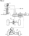
- a front axle 19 that includes a differential device accommodated in a differential case 20.
- a ring gear 21 is fixed to the differential case 20.
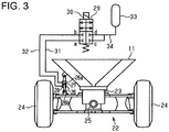
- an axle support member 23 is provided in the lower part of the body 11 to support a rear axle 22.
- the rear axle 22 includes a rocking shaft 25 and has at the opposite ends thereof steerable rear wheels 24.
- the axle support member 23 supports the rocking shaft 25 rotatably so that the rear axle 22 is supported pivotally with respect to the body 11. That is, the rear wheels 24 are swingable up and down.
- a dual-action type hydraulic cylinder 26 is provided between the body 11 and the rear axle 22 to temporally restrict the pivoting motion of the rear axle 22 while the forklift truck 10 is being turned.
- the hydraulic cylinder 26 serving as a swing lock cylinder has a cylinder tube 26a that is pivotally connected at one end thereof to the body 11.
- the hydraulic cylinder 26 also has a piston rod 26b that is connected to the rear axle 22.
- the hydraulic cylinder 26 has a first oil chamber 27 provided on the piston head side and a second oil chamber 28 provided on the side of the piston rod 26b that are formed integrally with the hydraulic cylinder 26.
- the first oil chamber 27 and the second oil chamber 28 are connected to or disconnected from each other by a solenoid-operated valve 29 having an electromagnetic solenoid 30.
- the valve 29 is a four-port two-way switching valve having ports a, b, c, d.
- the valve 29 has therein a spool (not shown).
- the solenoid 30 shifts the spool between the connection position and the disconnection position. In the connection position of the valve 29 with the solenoid 30 energized, the spool connects the port a to the port c and the port b to the port d, respectively. In the disconnection position of the valve 29 with the solenoid 30 deenergized, the spool disconnects the associated ports a, c and b, d from each other.
- the valve 29 is normally closed, so that when the solenoid 30 is deenergized, the spool is shifted to the disconnection position by a spring (not shown).
- the first oil chamber 27 is connected to the port a through a passage 31, while the second oil chamber 28 is connected to the port b through a passage 32.
- a passage 34 connects the ports c, d to an accumulator 33 that is formed integrally with the hydraulic cylinder 26.
- the rear axle 22 is pivotally supported by the body 11.
- the pivoting motion of the rear axle 22 can be restricted.
- a controller 35 is mounted on the body 11.
- the controller 35 includes a microcomputer and controls to restrict the pivoting motion of the rear axle 22 while the forklift truck 10 is being turned and to limit the vehicle traveling speed.
- a yaw rate sensor 36, a first height sensor 37, a second height sensor 38, a vehicle speed sensor 39, and a load sensor 40 are electrically connected to the input of the controller 35.
- the controller 35 determines the yaw rate, the vehicle speed and the load based on detection signals sent from the yaw rate sensor 36, the vehicle speed sensor 39, and the load sensor 40, respectively.
- the controller 35 further determines the first height position signal and the second height position signal based on the first height sensor 37 and the second height sensor 38, respectively to determine whether the fork 14 (lift bracket 13) is at higher fork height or at lower fork height.
- the controller 35 determines the lateral acceleration (lateral G) applied to the body 11 when the forklift truck 10 is turned based on the detection signal from the yaw rate sensor 36.
- the yaw rate sensor 36 and the controller 35 serving as lateral acceleration sensor of the present invention determine the lateral acceleration applied to the body 11 when the forklift truck 10 is turned.
- Drive circuits 41, 42 are electrically connected to the controller 35.
- the controller 35 drives the solenoid 30 corresponding to actuator of the present invention to restrict the pivoting of the rear axle 22 via the drive circuit 41 so as to temporally restrict the pivoting of the rear axle 22 while the forklift truck 10 is being turned. As a result, the tilting of the body 11 is suppressed and, therefore, the stability of the vehicle is ensured.
- the controller 35 further controls a traveling motor 43 via the drive circuit 42 so as to limit the vehicle traveling speed when the forklift truck 10 is turned. That is, the controller 35 corresponds to vehicle speed limiter to limit the vehicle traveling speed when the forklift truck 10 is turned.
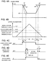
- the time charts illustrate the vehicle speed, the lateral acceleration, the vehicle speed limit on-off command, the swing lock on-off command for temporally restricting the pivoting of the rear axle 22 while the forklift truck 10 is being turned, and the vehicle speed recovery flag, respectively.
- the controller 35 drives the solenoid 30 based on the measured lateral acceleration so as to temporally restrict the pivoting of the rear axle 22 while the forklift truck 10 is being turned and also controls the traveling motor 43 based on the lateral acceleration so as to limit the vehicle traveling speed when the forklift truck 10 is turned.
- the lateral acceleration increases. After the lateral acceleration exceeds its maximum value, the lateral acceleration decreases.
- the vehicle speed limit command is turned ON, as shown in FIG. 4C , and the swing lock command is turned ON to temporally restrict the pivoting of the rear axle 22, as shown in FIG. 4D .
- the swing lock command is turned ON to temporally restrict the pivoting of the rear axle 22, as shown in FIG. 4D .
- FIG. 4A when the forklift truck 10 is turned, the vehicle speed decreases and then returns to the original vehicle speed.
- the lateral acceleration threshold value th2 which is used to judge whether the vehicle traveling speed should be limited is set smaller than the lateral acceleration threshold value th1 which is used to judge whether the pivoting of the rear axle 22 should be temporally restricted.
- the lateral acceleration threshold values th2 which is used to judge whether the vehicle traveling speed should be limited and the lateral acceleration threshold value th1 correspond to the first and second lateral acceleration threshold values of the present invention, respectively.
- the lateral acceleration threshold value th3 which is used to judge whether the temporal restriction of the pivoting of the rear axle 22 while the forklift truck 10 is being turned should be released is set smaller than the lateral acceleration threshold value th2 which is used to judge whether the limitation of the vehicle traveling speed should be released.
- the lateral acceleration threshold value th3 and the lateral acceleration threshold value th2 which is used to judge whether the limitation of the vehicle traveling speed should be released correspond to the third and fourth lateral acceleration threshold values of the present invention, respectively.
- the lateral acceleration threshold value th3 which is used to judge whether temporal restriction of the pivoting of the rear axle 22 should be released while the forklift truck 10 is being turned is set smaller than the lateral acceleration threshold value th1 which is used to judge whether the pivoting of the rear axle 22 should be temporally restricted while the forklift truck 10 is being turned.
- the control process proceeds to the step S2, where the controller 35 determines whether the lateral acceleration is at the threshold value th2 for limiting the vehicle speed or larger. If NO at the step S2, the controller 35 waits until the value of the lateral acceleration becomes the threshold value th2 for limiting the vehicle speed or larger. This processing corresponds to the state before the timing t1 shown in FIGS. 4A through 4E .
- the control process proceeds to the step S3, where the controller 35 controls the traveling motor 43 to limit the vehicle speed while the forklift truck 10 is being turned. Accordingly, the vehicle speed is decreased from the original vehicle speed V1 to the turning speed limit value V2, as shown in FIG. 4A .
- the turning speed limit value V2 is changed based on the lateral acceleration.
- the controller 35 determines the deceleration ⁇ based on the yaw rate acceleration and the fork height position of the fork (low position or high position) as shown in FIG. 6 .
- the deceleration ⁇ is increased with an increase of the yaw rate acceleration and is set larger when the fork position is higher.
- the controller 35 increases the deceleration ⁇ depending on the yaw rate acceleration so as to decrease the vehicle speed quickly.
- the upper limit a1 is set for the deceleration a. That is, the upper limit value a1 is set for restricting the vehicle traveling speed while the forklift truck 10 is being turned.
- the upper limit value a1 is set as the deceleration after the timing t1.
- the upper limit value a1 is set smaller than the value a2 which is used for control when the upper limit value of the deceleration is not set so that the vehicle decelerates slowly.
- step S3 the control process proceeds to the step S4, where the controller 35 determines whether the lateral acceleration is at or less than the threshold value th2 for limiting the vehicle speed. If NO at the step S4, the control process proceeds to the step S6, where the controller 35 determines whether the lateral acceleration is at or larger than the threshold value th1 for turning ON the swing lock. If No at the step S6, the controller 35 repeats to determines whether the lateral acceleration value is at the threshold value th1 for turning ON the swing lock or larger. This processing corresponds to the state between the timing t1 and the timing t2 shown in FIGS. 4A through 4E .
- step S6 determines whether YES at the step S6 (corresponding to the timing t2 shown in FIGS. 4A through 4E ).
- step S7 at which the solenoid 30 is energized to temporally restrict the pivoting of the rear axle 22 while the forklift truck 10 is being turned.
- step S7 After the processing at the step S7, the control process proceeds to the step S8, at which the vehicle speed recovery flag is turned on, or the state of the vehicle speed recovery flag is changed from 0 to 1, as shown in FIG. 4E .
- step S9 the controller 35 determines whether the lateral acceleration is at the threshold value th2 for limiting the vehicle speed or less. If NO at the step S9, the controller 35 waits until the lateral acceleration becomes the threshold value th2 for limiting the vehicle speed or less. This processing corresponds to the state between the timing t2 and the timing t3 shown in FIGS. 4A through 4E .
- the control process proceeds to the step S10, where the controller 35 controls the traveling motor 43 to stop the limitation of the vehicle speed while the forklift truck 10 is being turned.
- the vehicle speed is increased from the turning speed limit value V2 to the original vehicle speed V1 as shown in FIG. 4A .
- the upper limit value ⁇ 3 of the acceleration is set so that the controller 35 increases the vehicle speed more moderately by using the upper limit value a3 that is set smaller than a value a4 which is used for control when the upper limit value of the acceleration is not set.
- step S10 the control process proceeds to the step S11, where the controller 35 determines whether the lateral acceleration is at the threshold value th3 for turning OFF the swing lock or less. If NO at the step S11, the controller 35 waits until the lateral acceleration becomes the threshold value th3 for turning OFF the swing lock or less. This processing corresponds to the state between the timing t3 and the timing t4 shown in FIGS. 4A through 4E .
- step S11 If YES at the step S11 (corresponding to the timing t4 or the timing after the period T2 from the timing t3, shown in FIGS. 4A through 4E ), the control process proceeds to the step S12, where the controller 35 deenergizes the solenoid 30 to stop the temporal restriction of the pivoting of the rear axle 22 while the forklift truck 10 is being turned.
- step S12 the control process proceeds to the step S13 and the controller 35 changes the vehicle speed recovery flag from 1 to 0, as shown in FIG. 4E .
- the controller 35 sets the lateral acceleration threshold value th2 for limiting the vehicle speed to a value that is less than the lateral acceleration threshold value th1 for performing the swing lock and also sets the upper limit value a1 in the deceleration a.
- the controller 35 controls earlier to limit the vehicle speed so that the deceleration and the inclination of the body 11 caused by the deceleration are eliminated at the timing t2 for turning ON the swing lock of the swing lock function.
- the timings for performing the swing lock function and the vehicle speed limiting function shift with each other and the upper limit value a1 of the deceleration ⁇ is set, so that interference of the control is prevented. Furthermore, if the deceleration caused by the limitation of the vehicle speed and the inclination of the body 11 caused by the deceleration are not eliminated, the inclination of the body 11 may be suppressed so that the operator feels no strangeness. Moreover, if the operator does not arrange to return the acceleration pedal finely, the controller 35 controls earlier to limit the vehicle speed so that the body 11 is abundantly stable in the lateral direction thereof, with the result that the operation of the acceleration pedal is easier.
- the control process proceeds to the step S5 and the traveling motor 43 is controlled so as to stop the limitation of the vehicle speed while the forklift truck 10 is being turned.
- the lateral acceleration exceeds the threshold value th2 for limiting the vehicle speed and then is decreased to the threshold value th2 for limiting the vehicle speed or less without exceeding the threshold value th1 for performing the swing lock, the limitation of the vehicle speed is released without performing the swing lock.
- the forklift truck 10 according to the present embodiment offers the following advantages.
- the lateral acceleration threshold value th2 which is used in judging whether the vehicle traveling speed should be limited is set smaller than the lateral acceleration threshold value th1 which is used to in judging whether the pivoting motion of the rear axle 22 should be temporally restricted.
- the upper limit value a1 is set in the deceleration in limiting the vehicle traveling speed.
- the vehicle traveling speed is limited and the deceleration is limited at or below the upper limit value when the forklift truck 10 is turned so that the pivoting motion of the rear axle 22 is temporally restricted. Therefore, the operator of the forklift truck experiences no uncomfortable feel during the turning operation of the forklift truck and the vehicle may be turned smoothly and stably.
- the output paths of the swing lock function and the vehicle speed limiting function differ from each other. Therefore, if the swing lock function and the vehicle speed limiting function use the same value of the lateral acceleration, the timings to perform the control differ from each other due to the difference of their output paths. For example, when the limitation of the vehicle speed is performed while the vehicle is turned formerly and the swing lock of the swing lock function is performed afterwards with the body being inclined, the inclination of the body is retained, so that an operator possibly feels strange. According to the present embodiment, however, the problem may be prevented.
- the present invention has been described in the context of the present embodiment, but it is not limited to the present embodiment.
- the lateral acceleration is calculated based on the yaw rate measured by the yaw rate sensor
- the lateral acceleration may be calculated based on the wheel turning angle measured by a wheel turning angle sensor, specifically, the turning radius that is determined by the wheel turning angle, and the vehicle speed measured by a vehicle speed sensor.
- the forklift truck may include a yaw rate sensor, a wheel turning angle sensor, and a vehicle speed sensor.
- the lateral acceleration threshold value th3 which is used in judging whether the restriction of the pivoting of the rear axle 22 should be released is set smaller than the lateral acceleration threshold value th2 which is used in judging whether the limitation of the vehicle traveling speed is released.
- the lateral acceleration threshold value th10 which is used in judging whether the swing lock should be released may be set larger than the lateral acceleration threshold value th2 which is used in judging whether the limitation of the vehicle traveling speed should be released.
- the timing t3 for stopping the vehicle speed limitation of the vehicle speed limiting function occurs behind the timing t10 for releasing swing lock (turning OFF the swing lock) of the swing lock function. Since the change of the vehicle speed in the swing lock function is performed moderately, the lateral stability of the vehicle is not affected by stopping of the swing lock. After stopping the swing lock, since only the vehicle speed limiting function is performed, there occurs no interference of the control after stopping the vehicle speed limiting function.
- the threshold value th2 is used as the lateral acceleration threshold value which is used in judging whether the vehicle traveling speed should be limited and also as the lateral acceleration threshold value which is used in judging whether the limitation of the vehicle traveling speed should be released.
- the threshold value which is used in judging whether the vehicle traveling speed should be limited may differ from the threshold value which is used in judging whether the limitation of the vehicle traveling speed should be released.
- the forklift truck 10 may be configured so that the operator selects the application of the vehicle speed limiting function.
- an operation panel (a display) mounted on the forklift truck 10 may have a menu that allows the operator to select ON/OFF of the function.
- the operator who desires to use the limitation of the vehicle speed positively may select ON of the function because the use of only the vehicle speed limiting function can stabilize the forklift truck 10 in the lateral direction.
- An operator who is accustomed to the use of only the swing lock function may feel that the limitation of the vehicle speed by the vehicle speed limiting function is troublesome function that restricts the performance of the vehicle. In such a case, the function may be set OFF.
- the forklift truck 10 may be configured so that the operator selects the use of the swing lock function.
- an operation panel (display) mounted on the forklift truck 10 may have a menu to allow the operator to select ON/OFF of the function.
- the forklift truck 10 may improve the followability to road surface irregularities because only the use of the vehicle speed limiting function can stabilize the forklift truck 10 in the lateral direction.
- the forklift truck 10 may be configured so that the operator changes threshold values.
- an operation panel (a display) mounted on the forklift truck 10 may have a menu that allows the operator to change threshold values. For example, when the stability in the lateral direction is improved, the operator who desires to change the lateral acceleration threshold value of the vehicle speed limiting function to a smaller value for the vehicle speed limiting while the forklift truck 10 is being turned so as to improve the stability may use this menu. Since the vehicle speed limit value depends on operator's preference, tuning may be available. For example, a plurality of values of the vehicle speed limit may be selectable.
- the forklift truck 10 is not limited to a forklift truck having the fork 14 to carry loads, but it may be a forklift truck having various attachments including such as a hinged fork, a clamp, and a ram.
- the industrial vehicle is not limited to a forklift truck, but it may be other industrial vehicle of other type in which the axle is pivotally supported by the body such as a shovel loader.
Abstract
Description
- The present invention relates to an industrial vehicle such as a forklift truck.
- Japanese Patent No.
3129259 2005-96894 - It is conceivable to combine the disclosure of Japanese Patent No.
3129259 2005-96894 FIGS. 9A through 9D , that is, due to the time lag τ occurring between the time when command signal is generated and the time when the restriction of the pivoting motion of the axle and the vehicle speed limiting are actually effected. The operator of the vehicle feels that this time lag τ is uncomfortable. - The present invention is directed to providing an industrial vehicle that can be turned smoothly and stably so as to free an operator of the vehicle from uncomfortable feel when the industrial vehicle is turned.
- In accordance with a first aspect of the present invention, there is provided an industrial vehicle includes a body, an axle pivotally supported by the body, a lateral acceleration sensor determining lateral acceleration applied to the body when the industrial vehicle is turned, an actuator temporally restricting pivoting of the axle while the industrial vehicle is being turned, a vehicle speed limiter limiting vehicle traveling speed when the industrial vehicle is turned, and a controller driving the actuator based on the lateral acceleration determined by the lateral acceleration sensor to temporally restrict pivoting of the axle while the industrial vehicle is being turned and to limit traveling speed of the industrial vehicle by the vehicle speed limiter based on the lateral acceleration measured by the lateral acceleration sensor when the industrial vehicle is turned. In the controller, a first lateral acceleration threshold value which is used in judging whether traveling speed of the industrial vehicle should be limited is set smaller than a second lateral acceleration threshold value which is used in judging whether pivoting of the axle should be temporally restricted. In the controller, an upper limit value is set in deceleration in limiting traveling speed of the industrial vehicle.
- Other aspects and advantages of the invention will become apparent from the following description, taken in conjunction with the accompanying drawings, illustrating by way of example the principles of the invention.
- The invention together with objects and advantages thereof, may best be understood by reference to the following description of the embodiments together with the accompanying drawings in which:
-
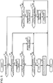
FIG. 1 is a side view showing a forklift truck according to an embodiment of the present invention; -
FIG. 2 is a diagrammatic view showing front and rear axles of the forklift truck ofFIG. 1 ; -
FIG. 3 is a diagrammatic view showing a vehicle body and the rear axle of the forklift truck ofFIG. 1 ; -
FIGS. 4A, 4B, 4C, 4D, and 4E are various time charts, showing the vehicle speed, the lateral acceleration, the vehicle speed limit on-off command, the swing lock on-off command, the vehicle speed recovery flag, respectively, to illustrate the operation of the forklift truck ofFIG. 1 ; -
FIG. 5 is a flow chart showing the control process for the operation of the forklift truck ofFIG. 1 ; -
FIG. 6 is a graph showing the relationship between the yaw acceleration and the deceleration in the forklift truck ofFIG. 1 ; -
FIGS. 7A, 7B, 7C, 7D, and 7E are various time charts showing the vehicle speed, the lateral acceleration, the vehicle speed limit on-off command, the swing lock on-off command, and the vehicle speed recovery flag, respectively, to illustrate another manner of operation of the forklift truck ofFIG. 1 ; -
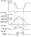
FIGS. 8A, 8B, 8C, and 8D are various time charts illustrating the operation of another example of the forklift truck ofFIG. 1 , showing the vehicle speed, the lateral acceleration, the vehicle speed limit on-off command, and the swing lock on-off command, respectively to illustrate another manner of operation of the forklift truck ofFIG. 1 ; and -
FIGS. 9A, 9B, 9C, and 9D are various time charts showing the vehicle speed, the lateral acceleration, the vehicle speed limit on-off command, and the swing lock on-off command, respectively, to illustrate the operation of the forklift truck of the background art. - The following will describe a forklift truck as an industrial vehicle according to an embodiment of the present invention with reference to accompanying the drawings. Referring to
FIG. 1 , the forklift truck which is designated generally byreference numeral 10 is a front drive, rear steering, four-wheel vehicle. Theforklift truck 10 includes abody 11 and anouter mast 12 the lower end of which is mounted to the front of thebody 11 and that is tiltable toward the front and the rear. Theouter mast 12 supportsinner masts 13 such that theinner masts 13 can be elevated and lowered. Theinner masts 13 support alift bracket 15, to whichforks 14 are fixed, such that thelift bracket 15 can be elevated and lowered. Asprocket wheel 16 is mounted to the upper part of theinner mast 13 and a chain (not shown) is provided to connect thesprocket wheel 16 and thelift bracket 15. - A
lift cylinder 17 is arranged behind theouter mast 12 and has a piston rod (not shown) that is connected to the upper portion of its correspondinginner mast 13. Atilt cylinder 18 is arranged at the front portion of thebody 11 and has apiston rod 18a that is connected to theouter mast 12. - Referring to
FIG. 2 , there is shown afront axle 19 that includes a differential device accommodated in adifferential case 20. Aring gear 21 is fixed to thedifferential case 20. Referring toFIG. 3 , anaxle support member 23 is provided in the lower part of thebody 11 to support arear axle 22. Therear axle 22 includes arocking shaft 25 and has at the opposite ends thereof steerablerear wheels 24. Theaxle support member 23 supports the rockingshaft 25 rotatably so that therear axle 22 is supported pivotally with respect to thebody 11. That is, therear wheels 24 are swingable up and down. - A dual-action type
hydraulic cylinder 26 is provided between thebody 11 and therear axle 22 to temporally restrict the pivoting motion of therear axle 22 while theforklift truck 10 is being turned. Thehydraulic cylinder 26 serving as a swing lock cylinder has acylinder tube 26a that is pivotally connected at one end thereof to thebody 11. Thehydraulic cylinder 26 also has apiston rod 26b that is connected to therear axle 22. - The
hydraulic cylinder 26 has a first oil chamber 27 provided on the piston head side and asecond oil chamber 28 provided on the side of thepiston rod 26b that are formed integrally with thehydraulic cylinder 26. The first oil chamber 27 and thesecond oil chamber 28 are connected to or disconnected from each other by a solenoid-operatedvalve 29 having anelectromagnetic solenoid 30. - The
valve 29 is a four-port two-way switching valve having ports a, b, c, d. Thevalve 29 has therein a spool (not shown). Thesolenoid 30 shifts the spool between the connection position and the disconnection position. In the connection position of thevalve 29 with thesolenoid 30 energized, the spool connects the port a to the port c and the port b to the port d, respectively. In the disconnection position of thevalve 29 with thesolenoid 30 deenergized, the spool disconnects the associated ports a, c and b, d from each other. Thevalve 29 is normally closed, so that when thesolenoid 30 is deenergized, the spool is shifted to the disconnection position by a spring (not shown). - The first oil chamber 27 is connected to the port a through a
passage 31, while thesecond oil chamber 28 is connected to the port b through apassage 32. Apassage 34 connects the ports c, d to anaccumulator 33 that is formed integrally with thehydraulic cylinder 26. When thesolenoid 30 is energized, thehydraulic cylinder 26 is fixed through thevalve 29, so that therear axle 22 is locked so as not to move up and down and the up-down swing of therear wheels 24 is prevented. As a result, the pivoting of therear axle 22 is temporally restricted while theforklift truck 10 is being turned. - In the
forklift truck 10 as an industrial vehicle, therear axle 22 is pivotally supported by thebody 11. The pivoting motion of therear axle 22 can be restricted. Referring toFIG. 2 , acontroller 35 is mounted on thebody 11. Thecontroller 35 includes a microcomputer and controls to restrict the pivoting motion of therear axle 22 while theforklift truck 10 is being turned and to limit the vehicle traveling speed. - A
yaw rate sensor 36, afirst height sensor 37, asecond height sensor 38, avehicle speed sensor 39, and aload sensor 40 are electrically connected to the input of thecontroller 35. Thecontroller 35 determines the yaw rate, the vehicle speed and the load based on detection signals sent from theyaw rate sensor 36, thevehicle speed sensor 39, and theload sensor 40, respectively. Thecontroller 35 further determines the first height position signal and the second height position signal based on thefirst height sensor 37 and thesecond height sensor 38, respectively to determine whether the fork 14 (lift bracket 13) is at higher fork height or at lower fork height. - The
controller 35 determines the lateral acceleration (lateral G) applied to thebody 11 when theforklift truck 10 is turned based on the detection signal from theyaw rate sensor 36. In the present embodiment, theyaw rate sensor 36 and thecontroller 35 serving as lateral acceleration sensor of the present invention determine the lateral acceleration applied to thebody 11 when theforklift truck 10 is turned. - Drive
circuits controller 35. Thecontroller 35 drives thesolenoid 30 corresponding to actuator of the present invention to restrict the pivoting of therear axle 22 via thedrive circuit 41 so as to temporally restrict the pivoting of therear axle 22 while theforklift truck 10 is being turned. As a result, the tilting of thebody 11 is suppressed and, therefore, the stability of the vehicle is ensured. Thecontroller 35 further controls a travelingmotor 43 via thedrive circuit 42 so as to limit the vehicle traveling speed when theforklift truck 10 is turned. That is, thecontroller 35 corresponds to vehicle speed limiter to limit the vehicle traveling speed when theforklift truck 10 is turned. - The following will describe the operation of the
forklift truck 10. Referring toFIGS. 4A, 4B, 4C, 4D, and 4E , the time charts illustrate the vehicle speed, the lateral acceleration, the vehicle speed limit on-off command, the swing lock on-off command for temporally restricting the pivoting of therear axle 22 while theforklift truck 10 is being turned, and the vehicle speed recovery flag, respectively. - The
controller 35 drives thesolenoid 30 based on the measured lateral acceleration so as to temporally restrict the pivoting of therear axle 22 while theforklift truck 10 is being turned and also controls the travelingmotor 43 based on the lateral acceleration so as to limit the vehicle traveling speed when theforklift truck 10 is turned. - Referring to
FIG. 4B , when the vehicle begins to be turned, the lateral acceleration increases. After the lateral acceleration exceeds its maximum value, the lateral acceleration decreases. When theforklift truck 10 is turned, the vehicle speed limit command is turned ON, as shown inFIG. 4C , and the swing lock command is turned ON to temporally restrict the pivoting of therear axle 22, as shown inFIG. 4D . Referring toFIG. 4A , when theforklift truck 10 is turned, the vehicle speed decreases and then returns to the original vehicle speed. - As shown in
FIG. 4B , the lateral acceleration threshold value th2 which is used to judge whether the vehicle traveling speed should be limited is set smaller than the lateral acceleration threshold value th1 which is used to judge whether the pivoting of therear axle 22 should be temporally restricted. The lateral acceleration threshold values th2 which is used to judge whether the vehicle traveling speed should be limited and the lateral acceleration threshold value th1 correspond to the first and second lateral acceleration threshold values of the present invention, respectively. The lateral acceleration threshold value th3 which is used to judge whether the temporal restriction of the pivoting of therear axle 22 while theforklift truck 10 is being turned should be released is set smaller than the lateral acceleration threshold value th2 which is used to judge whether the limitation of the vehicle traveling speed should be released. The lateral acceleration threshold value th3 and the lateral acceleration threshold value th2 which is used to judge whether the limitation of the vehicle traveling speed should be released correspond to the third and fourth lateral acceleration threshold values of the present invention, respectively. The lateral acceleration threshold value th3 which is used to judge whether temporal restriction of the pivoting of therear axle 22 should be released while theforklift truck 10 is being turned is set smaller than the lateral acceleration threshold value th1 which is used to judge whether the pivoting of therear axle 22 should be temporally restricted while theforklift truck 10 is being turned. - Referring to the flow chart of
FIG. 5 , when the vehicle speed recovery flag is zero at the step S1, the control process proceeds to the step S2, where thecontroller 35 determines whether the lateral acceleration is at the threshold value th2 for limiting the vehicle speed or larger. If NO at the step S2, thecontroller 35 waits until the value of the lateral acceleration becomes the threshold value th2 for limiting the vehicle speed or larger. This processing corresponds to the state before the timing t1 shown inFIGS. 4A through 4E . - When the value of the lateral acceleration becomes the threshold value th2 for limiting the vehicle speed or larger (corresponding to the timing t1 shown in
FIGS. 4A through 4E ), the control process proceeds to the step S3, where thecontroller 35 controls the travelingmotor 43 to limit the vehicle speed while theforklift truck 10 is being turned. Accordingly, the vehicle speed is decreased from the original vehicle speed V1 to the turning speed limit value V2, as shown inFIG. 4A . The turning speed limit value V2 is changed based on the lateral acceleration. - In the controlling to limit the vehicle speed, the
controller 35 determines the deceleration α based on the yaw rate acceleration and the fork height position of the fork (low position or high position) as shown inFIG. 6 . As appreciated fromFIG. 6 , the deceleration α is increased with an increase of the yaw rate acceleration and is set larger when the fork position is higher. Thus, in order to increase the stability when the vehicle is steered quickly, thecontroller 35 increases the deceleration α depending on the yaw rate acceleration so as to decrease the vehicle speed quickly. The upper limit a1 is set for the deceleration a. That is, the upper limit value a1 is set for restricting the vehicle traveling speed while theforklift truck 10 is being turned. Referring toFIG. 4A , the upper limit value a1 is set as the deceleration after the timing t1. The upper limit value a1 is set smaller than the value a2 which is used for control when the upper limit value of the deceleration is not set so that the vehicle decelerates slowly. - After the
controller 35 performed the step S3, the control process proceeds to the step S4, where thecontroller 35 determines whether the lateral acceleration is at or less than the threshold value th2 for limiting the vehicle speed. If NO at the step S4, the control process proceeds to the step S6, where thecontroller 35 determines whether the lateral acceleration is at or larger than the threshold value th1 for turning ON the swing lock. If No at the step S6, thecontroller 35 repeats to determines whether the lateral acceleration value is at the threshold value th1 for turning ON the swing lock or larger. This processing corresponds to the state between the timing t1 and the timing t2 shown inFIGS. 4A through 4E . - If YES at the step S6 (corresponding to the timing t2 shown in
FIGS. 4A through 4E ), the control process proceeds to the step S7, at which thesolenoid 30 is energized to temporally restrict the pivoting of therear axle 22 while theforklift truck 10 is being turned. - After the processing at the step S7, the control process proceeds to the step S8, at which the vehicle speed recovery flag is turned on, or the state of the vehicle speed recovery flag is changed from 0 to 1, as shown in
FIG. 4E . - If YES at the step S1, or if the
controller 35 judges that the vehicle speed recovery flag is 1 at the step S1, the control process proceeds to the step S9, where thecontroller 35 determines whether the lateral acceleration is at the threshold value th2 for limiting the vehicle speed or less. If NO at the step S9, thecontroller 35 waits until the lateral acceleration becomes the threshold value th2 for limiting the vehicle speed or less. This processing corresponds to the state between the timing t2 and the timing t3 shown inFIGS. 4A through 4E . - When the
controller 35 determines that the lateral acceleration is at the threshold value th2 for limiting the vehicle speed or less at the step S9 (this corresponding to the timing t3 shown inFIGS. 4A through 4E ), the control process proceeds to the step S10, where thecontroller 35 controls the travelingmotor 43 to stop the limitation of the vehicle speed while theforklift truck 10 is being turned. By stopping the limitation of the vehicle speed, the vehicle speed is increased from the turning speed limit value V2 to the original vehicle speed V1 as shown inFIG. 4A . - In the processing of increasing the vehicle speed, the upper limit value α3 of the acceleration is set so that the
controller 35 increases the vehicle speed more moderately by using the upper limit value a3 that is set smaller than a value a4 which is used for control when the upper limit value of the acceleration is not set. - After the step S10 has been performed, the control process proceeds to the step S11, where the
controller 35 determines whether the lateral acceleration is at the threshold value th3 for turning OFF the swing lock or less. If NO at the step S11, thecontroller 35 waits until the lateral acceleration becomes the threshold value th3 for turning OFF the swing lock or less. This processing corresponds to the state between the timing t3 and the timing t4 shown inFIGS. 4A through 4E . - If YES at the step S11 (corresponding to the timing t4 or the timing after the period T2 from the timing t3, shown in
FIGS. 4A through 4E ), the control process proceeds to the step S12, where thecontroller 35 deenergizes thesolenoid 30 to stop the temporal restriction of the pivoting of therear axle 22 while theforklift truck 10 is being turned. - After the step S12, the control process proceeds to the step S13 and the
controller 35 changes the vehicle speed recovery flag from 1 to 0, as shown inFIG. 4E . - Thus, the
controller 35 sets the lateral acceleration threshold value th2 for limiting the vehicle speed to a value that is less than the lateral acceleration threshold value th1 for performing the swing lock and also sets the upper limit value a1 in the deceleration a. In this case, regarding the time lag T1 between the ON command by the threshold value th1 and the ON command by the threshold value th2, thecontroller 35 controls earlier to limit the vehicle speed so that the deceleration and the inclination of thebody 11 caused by the deceleration are eliminated at the timing t2 for turning ON the swing lock of the swing lock function. - As a result, the timings for performing the swing lock function and the vehicle speed limiting function shift with each other and the upper limit value a1 of the deceleration α is set, so that interference of the control is prevented. Furthermore, if the deceleration caused by the limitation of the vehicle speed and the inclination of the
body 11 caused by the deceleration are not eliminated, the inclination of thebody 11 may be suppressed so that the operator feels no strangeness. Moreover, if the operator does not arrange to return the acceleration pedal finely, thecontroller 35 controls earlier to limit the vehicle speed so that thebody 11 is abundantly stable in the lateral direction thereof, with the result that the operation of the acceleration pedal is easier. - Referring to
FIGS. 7A, 7B, 7C, 7D, and 7E , when thecontroller 35 determines at the step S4 that the lateral acceleration is at or less than the threshold value th2 for limiting the vehicle speed (corresponding to the timing t5 shown inFIGS. 7A through 7E ), the control process proceeds to the step S5 and the travelingmotor 43 is controlled so as to stop the limitation of the vehicle speed while theforklift truck 10 is being turned. When the lateral acceleration exceeds the threshold value th2 for limiting the vehicle speed and then is decreased to the threshold value th2 for limiting the vehicle speed or less without exceeding the threshold value th1 for performing the swing lock, the limitation of the vehicle speed is released without performing the swing lock. - The
forklift truck 10 according to the present embodiment offers the following advantages. - (1) The
forklift truck 10 includes theyaw rate sensor 36, thecontroller 35, and thesolenoid 30 that temporarily restricts the pivoting motion of therear axle 22 while theforklift truck 10 is being turned. Theyaw rate sensor 36 and thecontroller 35 serving as lateral acceleration sensor of the present invention, determine lateral acceleration applied to thebody 11 when theforklift truck 10 is turned. Thecontroller 35 serves as vehicle speed limiter of the present invention that limits the vehicle traveling speed when theforklift truck 10 is turned. Thecontroller 35 serving as controller of the present invention controls thesolenoid 30 based on the detected lateral acceleration thereby to temporally restrict the pivoting motion of therear axle 22 while theforklift truck 10 is being turned (or to restrict the rolling motion of therear axle 22 relative to the body 11) and limits the vehicle traveling speed based on the lateral acceleration when theforklift truck 10 is turned. - In the
controller 35 serving as controller of the present invention, the lateral acceleration threshold value th2 which is used in judging whether the vehicle traveling speed should be limited is set smaller than the lateral acceleration threshold value th1 which is used to in judging whether the pivoting motion of therear axle 22 should be temporally restricted. Additionally, the upper limit value a1 is set in the deceleration in limiting the vehicle traveling speed. - Accordingly, the vehicle traveling speed is limited and the deceleration is limited at or below the upper limit value when the
forklift truck 10 is turned so that the pivoting motion of therear axle 22 is temporally restricted. Therefore, the operator of the forklift truck experiences no uncomfortable feel during the turning operation of the forklift truck and the vehicle may be turned smoothly and stably. - The output paths of the swing lock function and the vehicle speed limiting function differ from each other. Therefore, if the swing lock function and the vehicle speed limiting function use the same value of the lateral acceleration, the timings to perform the control differ from each other due to the difference of their output paths. For example, when the limitation of the vehicle speed is performed while the vehicle is turned formerly and the swing lock of the swing lock function is performed afterwards with the body being inclined, the inclination of the body is retained, so that an operator possibly feels strange. According to the present embodiment, however, the problem may be prevented.
- (2) In the
controller 35 serving as controller of the present invention, the lateral acceleration threshold value th3 which is used in judging whether the restriction of the pivoting of therear axle 22 should be released is set smaller than the lateral acceleration threshold value th2 which is used in judging whether the limitation of the vehicle traveling speed should be released. Such control of the forklift truck is practical. - (3) The lateral acceleration threshold value th3 which is used in judging whether restricting the pivoting of the
rear axle 22 should be released is set smaller than the lateral acceleration threshold value th1 which is used in judging whether the pivoting of therear axle 22 should be temporally restricted. Such control of the forklift truck is practical. - The present invention has been described in the context of the present embodiment, but it is not limited to the present embodiment. Although the lateral acceleration is calculated based on the yaw rate measured by the yaw rate sensor, the lateral acceleration may be calculated based on the wheel turning angle measured by a wheel turning angle sensor, specifically, the turning radius that is determined by the wheel turning angle, and the vehicle speed measured by a vehicle speed sensor. The forklift truck may include a yaw rate sensor, a wheel turning angle sensor, and a vehicle speed sensor.
- In the present embodiment, as shown in
FIG. 4B , the lateral acceleration threshold value th3 which is used in judging whether the restriction of the pivoting of therear axle 22 should be released is set smaller than the lateral acceleration threshold value th2 which is used in judging whether the limitation of the vehicle traveling speed is released. Alternatively, as shown inFIGS. 8A, 8B, 8C, and 8D , the lateral acceleration threshold value th10 which is used in judging whether the swing lock should be released may be set larger than the lateral acceleration threshold value th2 which is used in judging whether the limitation of the vehicle traveling speed should be released. - In this case, the timing t3 for stopping the vehicle speed limitation of the vehicle speed limiting function occurs behind the timing t10 for releasing swing lock (turning OFF the swing lock) of the swing lock function. Since the change of the vehicle speed in the swing lock function is performed moderately, the lateral stability of the vehicle is not affected by stopping of the swing lock. After stopping the swing lock, since only the vehicle speed limiting function is performed, there occurs no interference of the control after stopping the vehicle speed limiting function.
- As shown in
FIG. 4B , the threshold value th2 is used as the lateral acceleration threshold value which is used in judging whether the vehicle traveling speed should be limited and also as the lateral acceleration threshold value which is used in judging whether the limitation of the vehicle traveling speed should be released. Alternatively, the threshold value which is used in judging whether the vehicle traveling speed should be limited may differ from the threshold value which is used in judging whether the limitation of the vehicle traveling speed should be released. - The
forklift truck 10 may be configured so that the operator selects the application of the vehicle speed limiting function. For the purpose, an operation panel (a display) mounted on theforklift truck 10 may have a menu that allows the operator to select ON/OFF of the function. For example, the operator who desires to use the limitation of the vehicle speed positively may select ON of the function because the use of only the vehicle speed limiting function can stabilize theforklift truck 10 in the lateral direction. An operator who is accustomed to the use of only the swing lock function may feel that the limitation of the vehicle speed by the vehicle speed limiting function is troublesome function that restricts the performance of the vehicle. In such a case, the function may be set OFF. - The
forklift truck 10 may be configured so that the operator selects the use of the swing lock function. For the purpose, an operation panel (display) mounted on theforklift truck 10 may have a menu to allow the operator to select ON/OFF of the function. For example, when the swing lock function is OFF, theforklift truck 10 may improve the followability to road surface irregularities because only the use of the vehicle speed limiting function can stabilize theforklift truck 10 in the lateral direction. - The
forklift truck 10 may be configured so that the operator changes threshold values. For the purpose, an operation panel (a display) mounted on theforklift truck 10 may have a menu that allows the operator to change threshold values. For example, when the stability in the lateral direction is improved, the operator who desires to change the lateral acceleration threshold value of the vehicle speed limiting function to a smaller value for the vehicle speed limiting while theforklift truck 10 is being turned so as to improve the stability may use this menu. Since the vehicle speed limit value depends on operator's preference, tuning may be available. For example, a plurality of values of the vehicle speed limit may be selectable. - The
forklift truck 10 is not limited to a forklift truck having thefork 14 to carry loads, but it may be a forklift truck having various attachments including such as a hinged fork, a clamp, and a ram. - The industrial vehicle is not limited to a forklift truck, but it may be other industrial vehicle of other type in which the axle is pivotally supported by the body such as a shovel loader.
Claims (3)
- An industrial vehicle (10), wherein an axle (24) of the industrial vehicle (10) is pivotally supported by a body (11) of the industrial vehicle (10) and pivoting of the axle (24) can be restricted,
characterized by comprising:a lateral acceleration sensor (35, 36) determining lateral acceleration applied to the body (11) when the industrial vehicle (10) is turned;an actuator (30) temporally restricting the pivoting of the axle (24) while the industrial vehicle (10) is being turned;a vehicle speed limiter (35) limiting traveling speed of the industrial vehicle (10) when the industrial vehicle (10) is turned; anda controller (35) driving the actuator (30) based on the lateral acceleration determined by the lateral acceleration sensor (35, 36) to temporally restrict the pivoting of the axle (24) while the industrial vehicle (10) is being turned and to limit the traveling speed of the industrial vehicle (10) by the vehicle speed limiter (35) based on the lateral acceleration when the industrial vehicle (10) is turned,wherein in the controller, a first lateral acceleration threshold value (th2) which is used in judging whether the traveling speed of the industrial vehicle (10) should be limited is set smaller than a second lateral acceleration threshold value (th1) which is used in judging whether the pivoting of the axle (24) should be temporally restricted, and wherein in the controller, an upper limit value (α1) is set in deceleration in limiting the traveling speed of the industrial vehicle (10). - The industrial vehicle (10) according to claim 1, characterized in that in the controller (35), a third lateral acceleration threshold value (th3) which is used in judging whether restriction of the pivoting of the axle (24) should be released is set smaller than a fourth lateral acceleration threshold value (th2) which is used in judging whether limitation of the traveling speed should be released.
- The industrial vehicle (10) according to claim 2, characterized in that in the controller (35), the third lateral acceleration threshold value (th3, th10) which is used in judging whether the restriction of the pivoting of the axle (24) should be released is set smaller than the second lateral acceleration threshold value (th1) which is used in judging whether the pivoting of the axle (24) should be temporally restricted.
Applications Claiming Priority (1)
| Application Number | Priority Date | Filing Date | Title |
|---|---|---|---|
| JP2016238823A JP6665765B2 (en) | 2016-12-08 | 2016-12-08 | Industrial vehicles |
Publications (2)
| Publication Number | Publication Date |
|---|---|
| EP3333120A1 true EP3333120A1 (en) | 2018-06-13 |
| EP3333120B1 EP3333120B1 (en) | 2019-05-29 |
Family
ID=60515192
Family Applications (1)
| Application Number | Title | Priority Date | Filing Date |
|---|---|---|---|
| EP17204343.2A Active EP3333120B1 (en) | 2016-12-08 | 2017-11-29 | Industrial vehicle |
Country Status (4)
| Country | Link |
|---|---|
| US (1) | US10981762B2 (en) |
| EP (1) | EP3333120B1 (en) |
| JP (1) | JP6665765B2 (en) |
| CN (1) | CN108178106B (en) |
Families Citing this family (4)
| Publication number | Priority date | Publication date | Assignee | Title |
|---|---|---|---|---|
| US10462972B2 (en) | 2016-09-15 | 2019-11-05 | Harvestmoore, L.L.C. | Methods for automated pruning and harvesting of fruit plants utilizing a graphic processor unit |
| US11143261B2 (en) * | 2017-05-10 | 2021-10-12 | Harvestmoore, L.L.C. | Shock damping systems and methods for using shock damping systems |
| US20210214205A1 (en) * | 2020-01-10 | 2021-07-15 | Brooks Strong | Forklift safety system |
| JP2022094177A (en) * | 2020-12-14 | 2022-06-24 | 株式会社豊田自動織機 | Engine type industrial vehicle |
Citations (3)
| Publication number | Priority date | Publication date | Assignee | Title |
|---|---|---|---|---|
| EP0913278A2 (en) * | 1997-10-30 | 1999-05-06 | Kabushiki Kaisha Toyoda Jidoshokki Seisakusho | Axle tilt control method and apparatus for industrial vehicles |
| EP0913279A2 (en) * | 1997-10-31 | 1999-05-06 | Kabushiki Kaisha Toyoda Jidoshokki Seisakusho | Apparatus and method for restricting pivoting of industrial vehicles axles |
| JP2005096894A (en) | 2003-09-22 | 2005-04-14 | Toyota Industries Corp | Traveling control device of industrial vehicle |
Family Cites Families (9)
| Publication number | Priority date | Publication date | Assignee | Title |
|---|---|---|---|---|
| US6266594B1 (en) * | 1997-04-23 | 2001-07-24 | Kabushiki Kaisha Toyoda Jidoshokki Seisakusho | Body swing control apparatus for industrial vehicles |
| JPH115419A (en) * | 1997-06-18 | 1999-01-12 | Toyota Autom Loom Works Ltd | Car body rocking control device for industrial vehicle |
| JP3161381B2 (en) * | 1997-10-06 | 2001-04-25 | 株式会社豊田自動織機製作所 | Oscillation control device for industrial vehicles |
| JP3334582B2 (en) * | 1997-12-02 | 2002-10-15 | 株式会社豊田自動織機 | Industrial vehicle body swing control device and industrial vehicle |
| JP3925540B2 (en) * | 2005-03-23 | 2007-06-06 | トヨタ自動車株式会社 | Vehicle travel control device |
| JP5556523B2 (en) * | 2010-09-13 | 2014-07-23 | トヨタ自動車株式会社 | Vehicle control device |
| WO2013190821A1 (en) * | 2012-06-19 | 2013-12-27 | 住友重機械工業株式会社 | Motor driving device for forklifts and forklifts using same |
| JP6221858B2 (en) | 2014-03-13 | 2017-11-01 | 株式会社豊田自動織機 | Industrial vehicle travel control device |
| JP6801417B2 (en) * | 2016-12-08 | 2020-12-16 | 株式会社豊田自動織機 | Industrial vehicle |
-
2016
- 2016-12-08 JP JP2016238823A patent/JP6665765B2/en active Active
-
2017
- 2017-11-29 EP EP17204343.2A patent/EP3333120B1/en active Active
- 2017-12-07 CN CN201711283756.1A patent/CN108178106B/en active Active
- 2017-12-07 US US15/834,186 patent/US10981762B2/en active Active
Patent Citations (4)
| Publication number | Priority date | Publication date | Assignee | Title |
|---|---|---|---|---|
| EP0913278A2 (en) * | 1997-10-30 | 1999-05-06 | Kabushiki Kaisha Toyoda Jidoshokki Seisakusho | Axle tilt control method and apparatus for industrial vehicles |
| EP0913279A2 (en) * | 1997-10-31 | 1999-05-06 | Kabushiki Kaisha Toyoda Jidoshokki Seisakusho | Apparatus and method for restricting pivoting of industrial vehicles axles |
| JP3129259B2 (en) | 1997-10-31 | 2001-01-29 | 株式会社豊田自動織機製作所 | Axle swing control method and axle swing control device for industrial vehicle |
| JP2005096894A (en) | 2003-09-22 | 2005-04-14 | Toyota Industries Corp | Traveling control device of industrial vehicle |
Also Published As
| Publication number | Publication date |
|---|---|
| EP3333120B1 (en) | 2019-05-29 |
| US10981762B2 (en) | 2021-04-20 |
| CN108178106A (en) | 2018-06-19 |
| JP6665765B2 (en) | 2020-03-13 |
| CN108178106B (en) | 2020-03-27 |
| JP2018095337A (en) | 2018-06-21 |
| US20180162705A1 (en) | 2018-06-14 |
Similar Documents
| Publication | Publication Date | Title |
|---|---|---|
| EP3333120B1 (en) | Industrial vehicle | |
| EP1950171B1 (en) | Travel control apparatus for industrial vehicle | |
| US7165643B2 (en) | Industrial truck having increased static/quasi-static and dynamic tipping stability | |
| JP3129259B2 (en) | Axle swing control method and axle swing control device for industrial vehicle | |
| US7706947B2 (en) | Industrial truck having increased static or quasi-static tipping stability | |
| US7735609B2 (en) | Controller of industrial vehicle, industrial vehicle, and control method for industrial vehicle | |
| US4901811A (en) | Vehicle steering system for adjusting tire characteristic | |
| EP3333121B1 (en) | Industrial vehicle | |
| JP4944537B2 (en) | Travel controller for hydraulically driven vehicle | |
| JP4924584B2 (en) | Pitching suppression device for industrial vehicles | |
| KR20150114842A (en) | Forklift fork kept horizontality system and that control method | |
| JPH09315125A (en) | Control device for industrial vehicle | |
| JP2008195519A (en) | Traveling control device for industrial vehicle | |
| JP2006151305A (en) | Control device for working vehicle | |
| JP6471642B2 (en) | Industrial vehicle | |
| JP7024637B2 (en) | Industrial vehicle | |
| JPH04256698A (en) | Fork lift control device | |
| JPH04306175A (en) | Power steering for forklift | |
| JP2000191295A (en) | Tilting speed control device of fork lift truck | |
| JPH01220700A (en) | Shock absober for fork lift | |
| JPH0732843A (en) | Posture control device for work vehicle | |
| JPS59202919A (en) | Controller of cornering posture for motor car | |
| JPH08150820A (en) | Suspension device of vehicle | |
| JPH10164924A (en) | Traveling vehicle for working |
Legal Events
| Date | Code | Title | Description |
|---|---|---|---|
| PUAI | Public reference made under article 153(3) epc to a published international application that has entered the european phase |
Free format text: ORIGINAL CODE: 0009012 |
|
| STAA | Information on the status of an ep patent application or granted ep patent |
Free format text: STATUS: REQUEST FOR EXAMINATION WAS MADE |
|
| 17P | Request for examination filed |
Effective date: 20171129 |
|
| AK | Designated contracting states |
Kind code of ref document: A1 Designated state(s): AL AT BE BG CH CY CZ DE DK EE ES FI FR GB GR HR HU IE IS IT LI LT LU LV MC MK MT NL NO PL PT RO RS SE SI SK SM TR |
|
| AX | Request for extension of the european patent |
Extension state: BA ME |
|
| GRAP | Despatch of communication of intention to grant a patent |
Free format text: ORIGINAL CODE: EPIDOSNIGR1 |
|
| STAA | Information on the status of an ep patent application or granted ep patent |
Free format text: STATUS: GRANT OF PATENT IS INTENDED |
|
| RIC1 | Information provided on ipc code assigned before grant |
Ipc: B60G 17/005 20060101ALI20181210BHEP Ipc: B60G 17/016 20060101ALI20181210BHEP Ipc: B66F 17/00 20060101ALI20181210BHEP Ipc: B66F 9/075 20060101AFI20181210BHEP |
|
| INTG | Intention to grant announced |
Effective date: 20190107 |
|
| GRAS | Grant fee paid |
Free format text: ORIGINAL CODE: EPIDOSNIGR3 |
|
| GRAA | (expected) grant |
Free format text: ORIGINAL CODE: 0009210 |
|
| STAA | Information on the status of an ep patent application or granted ep patent |
Free format text: STATUS: THE PATENT HAS BEEN GRANTED |
|
| AK | Designated contracting states |
Kind code of ref document: B1 Designated state(s): AL AT BE BG CH CY CZ DE DK EE ES FI FR GB GR HR HU IE IS IT LI LT LU LV MC MK MT NL NO PL PT RO RS SE SI SK SM TR |
|
| REG | Reference to a national code |
Ref country code: GB Ref legal event code: FG4D |
|
| REG | Reference to a national code |
Ref country code: CH Ref legal event code: EP |
|
| REG | Reference to a national code |
Ref country code: AT Ref legal event code: REF Ref document number: 1138138 Country of ref document: AT Kind code of ref document: T Effective date: 20190615 |
|
| REG | Reference to a national code |
Ref country code: DE Ref legal event code: R096 Ref document number: 602017004214 Country of ref document: DE |
|
| REG | Reference to a national code |
Ref country code: IE Ref legal event code: FG4D |
|
| REG | Reference to a national code |
Ref country code: NL Ref legal event code: MP Effective date: 20190529 |
|
| REG | Reference to a national code |
Ref country code: LT Ref legal event code: MG4D |
|
| PG25 | Lapsed in a contracting state [announced via postgrant information from national office to epo] |
Ref country code: LT Free format text: LAPSE BECAUSE OF FAILURE TO SUBMIT A TRANSLATION OF THE DESCRIPTION OR TO PAY THE FEE WITHIN THE PRESCRIBED TIME-LIMIT Effective date: 20190529 Ref country code: SE Free format text: LAPSE BECAUSE OF FAILURE TO SUBMIT A TRANSLATION OF THE DESCRIPTION OR TO PAY THE FEE WITHIN THE PRESCRIBED TIME-LIMIT Effective date: 20190529 Ref country code: FI Free format text: LAPSE BECAUSE OF FAILURE TO SUBMIT A TRANSLATION OF THE DESCRIPTION OR TO PAY THE FEE WITHIN THE PRESCRIBED TIME-LIMIT Effective date: 20190529 Ref country code: AL Free format text: LAPSE BECAUSE OF FAILURE TO SUBMIT A TRANSLATION OF THE DESCRIPTION OR TO PAY THE FEE WITHIN THE PRESCRIBED TIME-LIMIT Effective date: 20190529 Ref country code: NO Free format text: LAPSE BECAUSE OF FAILURE TO SUBMIT A TRANSLATION OF THE DESCRIPTION OR TO PAY THE FEE WITHIN THE PRESCRIBED TIME-LIMIT Effective date: 20190829 Ref country code: ES Free format text: LAPSE BECAUSE OF FAILURE TO SUBMIT A TRANSLATION OF THE DESCRIPTION OR TO PAY THE FEE WITHIN THE PRESCRIBED TIME-LIMIT Effective date: 20190529 Ref country code: PT Free format text: LAPSE BECAUSE OF FAILURE TO SUBMIT A TRANSLATION OF THE DESCRIPTION OR TO PAY THE FEE WITHIN THE PRESCRIBED TIME-LIMIT Effective date: 20190930 Ref country code: HR Free format text: LAPSE BECAUSE OF FAILURE TO SUBMIT A TRANSLATION OF THE DESCRIPTION OR TO PAY THE FEE WITHIN THE PRESCRIBED TIME-LIMIT Effective date: 20190529 |
|
| PG25 | Lapsed in a contracting state [announced via postgrant information from national office to epo] |
Ref country code: BG Free format text: LAPSE BECAUSE OF FAILURE TO SUBMIT A TRANSLATION OF THE DESCRIPTION OR TO PAY THE FEE WITHIN THE PRESCRIBED TIME-LIMIT Effective date: 20190829 Ref country code: GR Free format text: LAPSE BECAUSE OF FAILURE TO SUBMIT A TRANSLATION OF THE DESCRIPTION OR TO PAY THE FEE WITHIN THE PRESCRIBED TIME-LIMIT Effective date: 20190830 Ref country code: RS Free format text: LAPSE BECAUSE OF FAILURE TO SUBMIT A TRANSLATION OF THE DESCRIPTION OR TO PAY THE FEE WITHIN THE PRESCRIBED TIME-LIMIT Effective date: 20190529 Ref country code: LV Free format text: LAPSE BECAUSE OF FAILURE TO SUBMIT A TRANSLATION OF THE DESCRIPTION OR TO PAY THE FEE WITHIN THE PRESCRIBED TIME-LIMIT Effective date: 20190529 |
|
| REG | Reference to a national code |
Ref country code: AT Ref legal event code: MK05 Ref document number: 1138138 Country of ref document: AT Kind code of ref document: T Effective date: 20190529 |
|
| PG25 | Lapsed in a contracting state [announced via postgrant information from national office to epo] |
Ref country code: EE Free format text: LAPSE BECAUSE OF FAILURE TO SUBMIT A TRANSLATION OF THE DESCRIPTION OR TO PAY THE FEE WITHIN THE PRESCRIBED TIME-LIMIT Effective date: 20190529 Ref country code: AT Free format text: LAPSE BECAUSE OF FAILURE TO SUBMIT A TRANSLATION OF THE DESCRIPTION OR TO PAY THE FEE WITHIN THE PRESCRIBED TIME-LIMIT Effective date: 20190529 Ref country code: DK Free format text: LAPSE BECAUSE OF FAILURE TO SUBMIT A TRANSLATION OF THE DESCRIPTION OR TO PAY THE FEE WITHIN THE PRESCRIBED TIME-LIMIT Effective date: 20190529 Ref country code: NL Free format text: LAPSE BECAUSE OF FAILURE TO SUBMIT A TRANSLATION OF THE DESCRIPTION OR TO PAY THE FEE WITHIN THE PRESCRIBED TIME-LIMIT Effective date: 20190529 Ref country code: RO Free format text: LAPSE BECAUSE OF FAILURE TO SUBMIT A TRANSLATION OF THE DESCRIPTION OR TO PAY THE FEE WITHIN THE PRESCRIBED TIME-LIMIT Effective date: 20190529 Ref country code: CZ Free format text: LAPSE BECAUSE OF FAILURE TO SUBMIT A TRANSLATION OF THE DESCRIPTION OR TO PAY THE FEE WITHIN THE PRESCRIBED TIME-LIMIT Effective date: 20190529 Ref country code: SK Free format text: LAPSE BECAUSE OF FAILURE TO SUBMIT A TRANSLATION OF THE DESCRIPTION OR TO PAY THE FEE WITHIN THE PRESCRIBED TIME-LIMIT Effective date: 20190529 |
|
| PG25 | Lapsed in a contracting state [announced via postgrant information from national office to epo] |
Ref country code: SM Free format text: LAPSE BECAUSE OF FAILURE TO SUBMIT A TRANSLATION OF THE DESCRIPTION OR TO PAY THE FEE WITHIN THE PRESCRIBED TIME-LIMIT Effective date: 20190529 |
|
| REG | Reference to a national code |
Ref country code: DE Ref legal event code: R097 Ref document number: 602017004214 Country of ref document: DE |
|
| PG25 | Lapsed in a contracting state [announced via postgrant information from national office to epo] |
Ref country code: TR Free format text: LAPSE BECAUSE OF FAILURE TO SUBMIT A TRANSLATION OF THE DESCRIPTION OR TO PAY THE FEE WITHIN THE PRESCRIBED TIME-LIMIT Effective date: 20190529 |
|
| PLBE | No opposition filed within time limit |
Free format text: ORIGINAL CODE: 0009261 |
|
| STAA | Information on the status of an ep patent application or granted ep patent |
Free format text: STATUS: NO OPPOSITION FILED WITHIN TIME LIMIT |
|
| PG25 | Lapsed in a contracting state [announced via postgrant information from national office to epo] |
Ref country code: PL Free format text: LAPSE BECAUSE OF FAILURE TO SUBMIT A TRANSLATION OF THE DESCRIPTION OR TO PAY THE FEE WITHIN THE PRESCRIBED TIME-LIMIT Effective date: 20190529 |
|
| 26N | No opposition filed |
Effective date: 20200303 |
|
| PG25 | Lapsed in a contracting state [announced via postgrant information from national office to epo] |
Ref country code: SI Free format text: LAPSE BECAUSE OF FAILURE TO SUBMIT A TRANSLATION OF THE DESCRIPTION OR TO PAY THE FEE WITHIN THE PRESCRIBED TIME-LIMIT Effective date: 20190529 |
|
| PG25 | Lapsed in a contracting state [announced via postgrant information from national office to epo] |
Ref country code: LU Free format text: LAPSE BECAUSE OF NON-PAYMENT OF DUE FEES Effective date: 20191129 Ref country code: MC Free format text: LAPSE BECAUSE OF FAILURE TO SUBMIT A TRANSLATION OF THE DESCRIPTION OR TO PAY THE FEE WITHIN THE PRESCRIBED TIME-LIMIT Effective date: 20190529 |
|
| REG | Reference to a national code |
Ref country code: BE Ref legal event code: MM Effective date: 20191130 |
|
| PG25 | Lapsed in a contracting state [announced via postgrant information from national office to epo] |
Ref country code: IE Free format text: LAPSE BECAUSE OF NON-PAYMENT OF DUE FEES Effective date: 20191129 |
|
| PG25 | Lapsed in a contracting state [announced via postgrant information from national office to epo] |
Ref country code: BE Free format text: LAPSE BECAUSE OF NON-PAYMENT OF DUE FEES Effective date: 20191130 |
|
| PG25 | Lapsed in a contracting state [announced via postgrant information from national office to epo] |
Ref country code: CY Free format text: LAPSE BECAUSE OF FAILURE TO SUBMIT A TRANSLATION OF THE DESCRIPTION OR TO PAY THE FEE WITHIN THE PRESCRIBED TIME-LIMIT Effective date: 20190529 |
|
| PG25 | Lapsed in a contracting state [announced via postgrant information from national office to epo] |
Ref country code: IS Free format text: LAPSE BECAUSE OF FAILURE TO SUBMIT A TRANSLATION OF THE DESCRIPTION OR TO PAY THE FEE WITHIN THE PRESCRIBED TIME-LIMIT Effective date: 20190929 |
|
| REG | Reference to a national code |
Ref country code: CH Ref legal event code: PL |
|
| PG25 | Lapsed in a contracting state [announced via postgrant information from national office to epo] |
Ref country code: HU Free format text: LAPSE BECAUSE OF FAILURE TO SUBMIT A TRANSLATION OF THE DESCRIPTION OR TO PAY THE FEE WITHIN THE PRESCRIBED TIME-LIMIT; INVALID AB INITIO Effective date: 20171129 Ref country code: MT Free format text: LAPSE BECAUSE OF FAILURE TO SUBMIT A TRANSLATION OF THE DESCRIPTION OR TO PAY THE FEE WITHIN THE PRESCRIBED TIME-LIMIT Effective date: 20190529 |
|
| PG25 | Lapsed in a contracting state [announced via postgrant information from national office to epo] |
Ref country code: CH Free format text: LAPSE BECAUSE OF NON-PAYMENT OF DUE FEES Effective date: 20201130 Ref country code: LI Free format text: LAPSE BECAUSE OF NON-PAYMENT OF DUE FEES Effective date: 20201130 |
|
| PG25 | Lapsed in a contracting state [announced via postgrant information from national office to epo] |
Ref country code: MK Free format text: LAPSE BECAUSE OF FAILURE TO SUBMIT A TRANSLATION OF THE DESCRIPTION OR TO PAY THE FEE WITHIN THE PRESCRIBED TIME-LIMIT Effective date: 20190529 |
|
| P01 | Opt-out of the competence of the unified patent court (upc) registered |
Effective date: 20230519 |
|
| PGFP | Annual fee paid to national office [announced via postgrant information from national office to epo] |
Ref country code: FR Payment date: 20230929 Year of fee payment: 7 |
|
| PGFP | Annual fee paid to national office [announced via postgrant information from national office to epo] |
Ref country code: GB Payment date: 20231006 Year of fee payment: 7 |
|
| PGFP | Annual fee paid to national office [announced via postgrant information from national office to epo] |
Ref country code: IT Payment date: 20231010 Year of fee payment: 7 Ref country code: DE Payment date: 20231003 Year of fee payment: 7 |