EP3333028B1 - A vehicle braking system and a method of operating a vehicle braking system - Google Patents
A vehicle braking system and a method of operating a vehicle braking system Download PDFInfo
- Publication number
- EP3333028B1 EP3333028B1 EP17195171.8A EP17195171A EP3333028B1 EP 3333028 B1 EP3333028 B1 EP 3333028B1 EP 17195171 A EP17195171 A EP 17195171A EP 3333028 B1 EP3333028 B1 EP 3333028B1
- Authority
- EP
- European Patent Office
- Prior art keywords
- brake
- controller
- simulator
- braking
- circuit
- Prior art date
- Legal status (The legal status is an assumption and is not a legal conclusion. Google has not performed a legal analysis and makes no representation as to the accuracy of the status listed.)
- Active
Links
Images


Classifications
-
- B—PERFORMING OPERATIONS; TRANSPORTING
- B60—VEHICLES IN GENERAL
- B60T—VEHICLE BRAKE CONTROL SYSTEMS OR PARTS THEREOF; BRAKE CONTROL SYSTEMS OR PARTS THEREOF, IN GENERAL; ARRANGEMENT OF BRAKING ELEMENTS ON VEHICLES IN GENERAL; PORTABLE DEVICES FOR PREVENTING UNWANTED MOVEMENT OF VEHICLES; VEHICLE MODIFICATIONS TO FACILITATE COOLING OF BRAKES
- B60T17/00—Component parts, details, or accessories of power brake systems not covered by groups B60T8/00, B60T13/00 or B60T15/00, or presenting other characteristic features
- B60T17/18—Safety devices; Monitoring
- B60T17/22—Devices for monitoring or checking brake systems; Signal devices
- B60T17/221—Procedure or apparatus for checking or keeping in a correct functioning condition of brake systems
-
- B—PERFORMING OPERATIONS; TRANSPORTING
- B60—VEHICLES IN GENERAL
- B60T—VEHICLE BRAKE CONTROL SYSTEMS OR PARTS THEREOF; BRAKE CONTROL SYSTEMS OR PARTS THEREOF, IN GENERAL; ARRANGEMENT OF BRAKING ELEMENTS ON VEHICLES IN GENERAL; PORTABLE DEVICES FOR PREVENTING UNWANTED MOVEMENT OF VEHICLES; VEHICLE MODIFICATIONS TO FACILITATE COOLING OF BRAKES
- B60T13/00—Transmitting braking action from initiating means to ultimate brake actuator with power assistance or drive; Brake systems incorporating such transmitting means, e.g. air-pressure brake systems
- B60T13/10—Transmitting braking action from initiating means to ultimate brake actuator with power assistance or drive; Brake systems incorporating such transmitting means, e.g. air-pressure brake systems with fluid assistance, drive, or release
- B60T13/66—Electrical control in fluid-pressure brake systems
- B60T13/662—Electrical control in fluid-pressure brake systems characterised by specified functions of the control system components
-
- B—PERFORMING OPERATIONS; TRANSPORTING
- B60—VEHICLES IN GENERAL
- B60T—VEHICLE BRAKE CONTROL SYSTEMS OR PARTS THEREOF; BRAKE CONTROL SYSTEMS OR PARTS THEREOF, IN GENERAL; ARRANGEMENT OF BRAKING ELEMENTS ON VEHICLES IN GENERAL; PORTABLE DEVICES FOR PREVENTING UNWANTED MOVEMENT OF VEHICLES; VEHICLE MODIFICATIONS TO FACILITATE COOLING OF BRAKES
- B60T13/00—Transmitting braking action from initiating means to ultimate brake actuator with power assistance or drive; Brake systems incorporating such transmitting means, e.g. air-pressure brake systems
- B60T13/10—Transmitting braking action from initiating means to ultimate brake actuator with power assistance or drive; Brake systems incorporating such transmitting means, e.g. air-pressure brake systems with fluid assistance, drive, or release
- B60T13/66—Electrical control in fluid-pressure brake systems
- B60T13/68—Electrical control in fluid-pressure brake systems by electrically-controlled valves
- B60T13/686—Electrical control in fluid-pressure brake systems by electrically-controlled valves in hydraulic systems or parts thereof
-
- B—PERFORMING OPERATIONS; TRANSPORTING
- B60—VEHICLES IN GENERAL
- B60T—VEHICLE BRAKE CONTROL SYSTEMS OR PARTS THEREOF; BRAKE CONTROL SYSTEMS OR PARTS THEREOF, IN GENERAL; ARRANGEMENT OF BRAKING ELEMENTS ON VEHICLES IN GENERAL; PORTABLE DEVICES FOR PREVENTING UNWANTED MOVEMENT OF VEHICLES; VEHICLE MODIFICATIONS TO FACILITATE COOLING OF BRAKES
- B60T13/00—Transmitting braking action from initiating means to ultimate brake actuator with power assistance or drive; Brake systems incorporating such transmitting means, e.g. air-pressure brake systems
- B60T13/74—Transmitting braking action from initiating means to ultimate brake actuator with power assistance or drive; Brake systems incorporating such transmitting means, e.g. air-pressure brake systems with electrical assistance or drive
- B60T13/745—Transmitting braking action from initiating means to ultimate brake actuator with power assistance or drive; Brake systems incorporating such transmitting means, e.g. air-pressure brake systems with electrical assistance or drive acting on a hydraulic system, e.g. a master cylinder
-
- B—PERFORMING OPERATIONS; TRANSPORTING
- B60—VEHICLES IN GENERAL
- B60T—VEHICLE BRAKE CONTROL SYSTEMS OR PARTS THEREOF; BRAKE CONTROL SYSTEMS OR PARTS THEREOF, IN GENERAL; ARRANGEMENT OF BRAKING ELEMENTS ON VEHICLES IN GENERAL; PORTABLE DEVICES FOR PREVENTING UNWANTED MOVEMENT OF VEHICLES; VEHICLE MODIFICATIONS TO FACILITATE COOLING OF BRAKES
- B60T7/00—Brake-action initiating means
- B60T7/02—Brake-action initiating means for personal initiation
- B60T7/04—Brake-action initiating means for personal initiation foot actuated
- B60T7/042—Brake-action initiating means for personal initiation foot actuated by electrical means, e.g. using travel or force sensors
-
- B—PERFORMING OPERATIONS; TRANSPORTING
- B60—VEHICLES IN GENERAL
- B60T—VEHICLE BRAKE CONTROL SYSTEMS OR PARTS THEREOF; BRAKE CONTROL SYSTEMS OR PARTS THEREOF, IN GENERAL; ARRANGEMENT OF BRAKING ELEMENTS ON VEHICLES IN GENERAL; PORTABLE DEVICES FOR PREVENTING UNWANTED MOVEMENT OF VEHICLES; VEHICLE MODIFICATIONS TO FACILITATE COOLING OF BRAKES
- B60T8/00—Arrangements for adjusting wheel-braking force to meet varying vehicular or ground-surface conditions, e.g. limiting or varying distribution of braking force
-
- B—PERFORMING OPERATIONS; TRANSPORTING
- B60—VEHICLES IN GENERAL
- B60T—VEHICLE BRAKE CONTROL SYSTEMS OR PARTS THEREOF; BRAKE CONTROL SYSTEMS OR PARTS THEREOF, IN GENERAL; ARRANGEMENT OF BRAKING ELEMENTS ON VEHICLES IN GENERAL; PORTABLE DEVICES FOR PREVENTING UNWANTED MOVEMENT OF VEHICLES; VEHICLE MODIFICATIONS TO FACILITATE COOLING OF BRAKES
- B60T8/00—Arrangements for adjusting wheel-braking force to meet varying vehicular or ground-surface conditions, e.g. limiting or varying distribution of braking force
- B60T8/17—Using electrical or electronic regulation means to control braking
-
- B—PERFORMING OPERATIONS; TRANSPORTING
- B60—VEHICLES IN GENERAL
- B60T—VEHICLE BRAKE CONTROL SYSTEMS OR PARTS THEREOF; BRAKE CONTROL SYSTEMS OR PARTS THEREOF, IN GENERAL; ARRANGEMENT OF BRAKING ELEMENTS ON VEHICLES IN GENERAL; PORTABLE DEVICES FOR PREVENTING UNWANTED MOVEMENT OF VEHICLES; VEHICLE MODIFICATIONS TO FACILITATE COOLING OF BRAKES
- B60T8/00—Arrangements for adjusting wheel-braking force to meet varying vehicular or ground-surface conditions, e.g. limiting or varying distribution of braking force
- B60T8/17—Using electrical or electronic regulation means to control braking
- B60T8/171—Detecting parameters used in the regulation; Measuring values used in the regulation
-
- B—PERFORMING OPERATIONS; TRANSPORTING
- B60—VEHICLES IN GENERAL
- B60T—VEHICLE BRAKE CONTROL SYSTEMS OR PARTS THEREOF; BRAKE CONTROL SYSTEMS OR PARTS THEREOF, IN GENERAL; ARRANGEMENT OF BRAKING ELEMENTS ON VEHICLES IN GENERAL; PORTABLE DEVICES FOR PREVENTING UNWANTED MOVEMENT OF VEHICLES; VEHICLE MODIFICATIONS TO FACILITATE COOLING OF BRAKES
- B60T8/00—Arrangements for adjusting wheel-braking force to meet varying vehicular or ground-surface conditions, e.g. limiting or varying distribution of braking force
- B60T8/32—Arrangements for adjusting wheel-braking force to meet varying vehicular or ground-surface conditions, e.g. limiting or varying distribution of braking force responsive to a speed condition, e.g. acceleration or deceleration
- B60T8/34—Arrangements for adjusting wheel-braking force to meet varying vehicular or ground-surface conditions, e.g. limiting or varying distribution of braking force responsive to a speed condition, e.g. acceleration or deceleration having a fluid pressure regulator responsive to a speed condition
- B60T8/40—Arrangements for adjusting wheel-braking force to meet varying vehicular or ground-surface conditions, e.g. limiting or varying distribution of braking force responsive to a speed condition, e.g. acceleration or deceleration having a fluid pressure regulator responsive to a speed condition comprising an additional fluid circuit including fluid pressurising means for modifying the pressure of the braking fluid, e.g. including wheel driven pumps for detecting a speed condition, or pumps which are controlled by means independent of the braking system
- B60T8/4072—Systems in which a driver input signal is used as a control signal for the additional fluid circuit which is normally used for braking
- B60T8/4081—Systems with stroke simulating devices for driver input
-
- B—PERFORMING OPERATIONS; TRANSPORTING
- B60—VEHICLES IN GENERAL
- B60T—VEHICLE BRAKE CONTROL SYSTEMS OR PARTS THEREOF; BRAKE CONTROL SYSTEMS OR PARTS THEREOF, IN GENERAL; ARRANGEMENT OF BRAKING ELEMENTS ON VEHICLES IN GENERAL; PORTABLE DEVICES FOR PREVENTING UNWANTED MOVEMENT OF VEHICLES; VEHICLE MODIFICATIONS TO FACILITATE COOLING OF BRAKES
- B60T8/00—Arrangements for adjusting wheel-braking force to meet varying vehicular or ground-surface conditions, e.g. limiting or varying distribution of braking force
- B60T8/32—Arrangements for adjusting wheel-braking force to meet varying vehicular or ground-surface conditions, e.g. limiting or varying distribution of braking force responsive to a speed condition, e.g. acceleration or deceleration
- B60T8/88—Arrangements for adjusting wheel-braking force to meet varying vehicular or ground-surface conditions, e.g. limiting or varying distribution of braking force responsive to a speed condition, e.g. acceleration or deceleration with failure responsive means, i.e. means for detecting and indicating faulty operation of the speed responsive control means
- B60T8/885—Arrangements for adjusting wheel-braking force to meet varying vehicular or ground-surface conditions, e.g. limiting or varying distribution of braking force responsive to a speed condition, e.g. acceleration or deceleration with failure responsive means, i.e. means for detecting and indicating faulty operation of the speed responsive control means using electrical circuitry
-
- B—PERFORMING OPERATIONS; TRANSPORTING
- B60—VEHICLES IN GENERAL
- B60T—VEHICLE BRAKE CONTROL SYSTEMS OR PARTS THEREOF; BRAKE CONTROL SYSTEMS OR PARTS THEREOF, IN GENERAL; ARRANGEMENT OF BRAKING ELEMENTS ON VEHICLES IN GENERAL; PORTABLE DEVICES FOR PREVENTING UNWANTED MOVEMENT OF VEHICLES; VEHICLE MODIFICATIONS TO FACILITATE COOLING OF BRAKES
- B60T8/00—Arrangements for adjusting wheel-braking force to meet varying vehicular or ground-surface conditions, e.g. limiting or varying distribution of braking force
- B60T8/32—Arrangements for adjusting wheel-braking force to meet varying vehicular or ground-surface conditions, e.g. limiting or varying distribution of braking force responsive to a speed condition, e.g. acceleration or deceleration
- B60T8/88—Arrangements for adjusting wheel-braking force to meet varying vehicular or ground-surface conditions, e.g. limiting or varying distribution of braking force responsive to a speed condition, e.g. acceleration or deceleration with failure responsive means, i.e. means for detecting and indicating faulty operation of the speed responsive control means
- B60T8/90—Arrangements for adjusting wheel-braking force to meet varying vehicular or ground-surface conditions, e.g. limiting or varying distribution of braking force responsive to a speed condition, e.g. acceleration or deceleration with failure responsive means, i.e. means for detecting and indicating faulty operation of the speed responsive control means using a simulated speed signal to test speed responsive control means
-
- B—PERFORMING OPERATIONS; TRANSPORTING
- B60—VEHICLES IN GENERAL
- B60T—VEHICLE BRAKE CONTROL SYSTEMS OR PARTS THEREOF; BRAKE CONTROL SYSTEMS OR PARTS THEREOF, IN GENERAL; ARRANGEMENT OF BRAKING ELEMENTS ON VEHICLES IN GENERAL; PORTABLE DEVICES FOR PREVENTING UNWANTED MOVEMENT OF VEHICLES; VEHICLE MODIFICATIONS TO FACILITATE COOLING OF BRAKES
- B60T2270/00—Further aspects of brake control systems not otherwise provided for
- B60T2270/40—Failsafe aspects of brake control systems
- B60T2270/404—Brake-by-wire or X-by-wire failsafe
-
- B—PERFORMING OPERATIONS; TRANSPORTING
- B60—VEHICLES IN GENERAL
- B60T—VEHICLE BRAKE CONTROL SYSTEMS OR PARTS THEREOF; BRAKE CONTROL SYSTEMS OR PARTS THEREOF, IN GENERAL; ARRANGEMENT OF BRAKING ELEMENTS ON VEHICLES IN GENERAL; PORTABLE DEVICES FOR PREVENTING UNWANTED MOVEMENT OF VEHICLES; VEHICLE MODIFICATIONS TO FACILITATE COOLING OF BRAKES
- B60T2270/00—Further aspects of brake control systems not otherwise provided for
- B60T2270/40—Failsafe aspects of brake control systems
- B60T2270/406—Test-mode; Self-diagnosis
-
- B—PERFORMING OPERATIONS; TRANSPORTING
- B60—VEHICLES IN GENERAL
- B60T—VEHICLE BRAKE CONTROL SYSTEMS OR PARTS THEREOF; BRAKE CONTROL SYSTEMS OR PARTS THEREOF, IN GENERAL; ARRANGEMENT OF BRAKING ELEMENTS ON VEHICLES IN GENERAL; PORTABLE DEVICES FOR PREVENTING UNWANTED MOVEMENT OF VEHICLES; VEHICLE MODIFICATIONS TO FACILITATE COOLING OF BRAKES
- B60T2270/00—Further aspects of brake control systems not otherwise provided for
- B60T2270/82—Brake-by-Wire, EHB
Definitions
- the present invention relates to vehicles having brake systems. It is known to provide a vehicle with a full-power brake system (also referred to as a "decoupled” or “brake-by-wire” system) in which driver applied force does not propagate to produce the actual braking force to the brake devices. Instead, fluid is pushed from the master cylinder into a simulator circuit while another mechanism provides the actual braking force. Although satisfactory for the intended purpose, a great number of valves and sensors must all be in working order to provide brake-by-wire operation, and it can be difficult to diagnose faults within the system.
- DE 10 2012 201535 A1 discloses a vehicle braking system comprising electrically controllable units which are provided to enable hydraulic tests of the actuator unit by disabling pressure fluid outflow from an operating unit into the brake circuit pressure lines.
- the invention provides a vehicle braking system including a master cylinder having an input side configured to receive an input from a brake pedal and an output side configured to provide a master cylinder output via a first outlet and a second outlet.
- a first braking circuit of the vehicle has at least one wheel cylinder coupled to the first master cylinder outlet via a first normally-open isolation valve and a first normally-open inlet valve
- a second braking circuit has at least one wheel cylinder coupled to the second master cylinder outlet via a second normally-open isolation valve and a second normally-open inlet valve.
- a brake pressure generator is provided separate from the brake pedal.
- a simulator circuit includes a pedal feel simulator coupled to the master cylinder output side through a switchable simulator valve, the simulator circuit being isolated from the first braking circuit when the first isolation valve is in a closed position.
- the pedal feel simulator provides a reaction force to the brake pedal when the switchable simulator valve is in an open position.
- a pressure sensor is positioned in the first braking circuit between the first isolation valve and an output of the brake pressure generator.
- a controller is programmed to, at a designated diagnostic time when the brake pedal is depressed to generate a brake pedal input while the vehicle is locked out from being driven by one or both of a parking brake and a transmission parking gear, open the simulator valve without closing the first isolation valve to place the pedal feel simulator in fluid communication with the pressure sensor of the first braking circuit, and to observe with the pressure sensor an increase in brake fluid pressure resulting from the brake pedal input.
- the controller is further programmed to check whether the relationship between the observed brake fluid pressure increase and the brake pedal input is within a predetermined acceptable range for continued operation of a brake-by-wire vehicle braking mode in which the master cylinder is coupled to the simulator circuit and decoupled from the first and second braking circuits, while brake fluid pressure to the wheel cylinders of the first and second braking circuits is provided solely by the brake pressure generator.
- the invention provides a method of operating a vehicle braking system utilizing a controller.
- the vehicle braking system is operated in a primary brake-by-wire braking mode including: A) receiving an input from a brake pedal at an input side of a master cylinder and providing a master cylinder output corresponding to the brake pedal input at an output side of the master cylinder output, B) closing, by a controller signal, a first normally-open isolation valve to isolate the output side of the master cylinder from a first braking circuit having at least one wheel cylinder, C) sending a controller signal to a switchable simulator valve to open a fluid connection between the master cylinder output side and a simulator circuit including a pedal feel simulator to provide a reaction force to the brake pedal, D) generating a braking request signal with a primary pressure sensor responsive to the input from the brake pedal, the braking request signal being sent to the controller, and E) driving a brake pressure generator of the first braking circuit with the controller responsive to the braking request signal to achieve braking at the at least one wheel
- a controller signal is sent, at a designated diagnostic time when the brake pedal is depressed to generate a brake pedal input while the vehicle is locked out from being driven by one or both of a parking brake and a transmission parking gear, to open the simulator valve without closing the first isolation valve to place the simulator circuit in fluid communication with a secondary pressure sensor of the first braking circuit.
- An increase in brake fluid pressure resulting from the brake pedal input is observed with the secondary pressure sensor, and the observed increase in brake fluid pressure is reported to the controller.
- the controller determines whether the relationship between the observed brake fluid pressure increase and brake pedal input is within a predetermined acceptable range for continued operation of the primary brake-by-wire braking mode.
- the braking system 20 of Fig. 1 includes a master cylinder 24 having an input side coupled with an input rod 25 to a brake pedal 28 to pressurize hydraulic fluid therein.
- the master cylinder 24 includes a first piston 26 1 that is coupled to the brake pedal 28 to move directly therewith.
- the first piston 26 1 pressurizes hydraulic fluid in a first chamber of the master cylinder 24 to be output from the first chamber at a first outlet 40 1 .
- a second piston 26 2 of the master cylinder 24 can be moved under the influence of fluid pressurized in the first chamber by the first piston 26 1 , without the second piston 26 2 having any direct connection to the first piston 26 1 or the brake pedal 28.
- the second piston 26 1 pressurizes hydraulic fluid in a second chamber of the master cylinder 24 to be output from the second chamber at a second outlet 40 2 .
- a fluid reservoir 32 is in fluid communication with the first and second chambers of the master cylinder 24 until the brake pedal 28 is initially actuated, at which time the pistons 26 1 , 26 2 block off the master cylinder chambers from the reservoir 32.
- a pedal travel sensor 36 is coupled to the brake pedal 28 and is operable to detect an amount of travel of the brake pedal 28, so that a corresponding signal can be sent to a controller 100 ( Fig. 4 ).
- the controller 100 can be a computer electrically coupled with each sensor and each electrically-operable valve of the braking system 20, to send signals thereto and/or receive signals therefrom to establish communication and control necessary to operate the braking system 20. As shown in the vehicle schematic of Fig. 4 , the controller 100 can further be coupled to one or both of a parking brake 104 and a transmission having a parking gear 108.
- the parking brake 104 can have an active position that locks out the vehicle from being driven (e.g., by mechanically locking at least one wheel of the vehicle against rotation, thus preventing movement of the vehicle under its own power).
- the transmission 108 can be a conventional automatic multi-speed transmission or another type of transmission that has a selectable parking gear that can be actuated to a position that locks out the vehicle from being driven (e.g., by mechanically locking an output of the transmission against rotation, thus preventing movement of the vehicle under its own power). Either one or both of the parking brake 104 or the transmission 108 can define an actively- or positively-"parked" condition of the vehicle.
- each of the braking circuits includes a pair of brake devices or wheel cylinders WC operable to slow down the wheels of a vehicle on which the braking system 20 is provided.
- the wheel cylinders WC of a particular circuit can be associated with a set of front vehicle wheels, a set of rear vehicle wheels, or a set of diagonal vehicle wheels.
- Each braking circuit includes an inlet valve 44 and an outlet valve 48 associated with each respective wheel cylinder WC.
- the inlet valves 44 are normally-open and can be electrically closed by the controller 100 to stop or limit pressurized hydraulic fluid supplied to the wheel cylinder WC.
- the outlet valves 48 are normally-closed and can be electrically opened by the controller 100 to relieve pressurized hydraulic fluid at the wheel cylinder WC, to the reservoir 32.
- Each of the master cylinder outlets 40 1 , 40 2 is coupled to one of the braking circuits through a normally-open isolation valve 52 1, 52 2 .
- Each of the isolation valves 52 1, 52 2 is operable to be closed by the controller 100 to fluidly separate or isolate the master cylinder 24, and thus the brake pedal 28, from the braking circuits having the wheel cylinders WC.
- the system 20 can be provided with an alternate or auxiliary device, separate from the brake pedal 28 and referred to herein as a brake pressure generator 60, for generating hydraulic fluid pressure to the wheel cylinders WC for the requisite braking need.
- the brake pressure generator 60 can include a plunger or piston 62 drivable in a cylinder by an actuator such as an electric motor 64 operated by the controller 100. As such, the brake pressure generator 60 is operable to drive pressurized hydraulic fluid to the wheel cylinders WC of the first and second braking circuits.
- an outlet 68 of the brake pressure generator 60 can be coupled, in parallel, to the first and second braking circuits through respective apply pressure control valves 72 1 , 72 2 .
- Each of the apply pressure control valves 72 1 , 72 2 can be a controller-modulated solenoid valve (e.g., having a range of open positions, or receiving a pulse-width modulation signal to achieve a similar effect) operable to control the pressure supplied from the brake pressure generator 60 to the wheel cylinders WC of the given braking circuit.
- the apply pressure control valves 72 1 , 72 2 can be coupled to respective brake fluid supply lines or passages, each of which extends between one of the isolation valves 52 1, 52 2 and the respective inlet valves 44 of the braking circuit.
- One or more pressure sensors 76 can be positioned along the fluid path between the brake pressure generator outlet 68 and the respective inlet valves 44 and operable to report the fluid pressure to the controller 100.
- the pressure sensor 76 can be referred to as an "active circuit" pressure sensor as it senses and reports the fluid pressure in the passage(s) coupled to the wheel cylinders WC, as contrasted with fluid pressure in the master cylinder 24 or a simulator circuit, which are not part of an active braking circuit during brake-by-wire operation.
- Additional sensors may be provided to monitor parameters of the piston 62 and/or the electric motor 64, and may include any one or more of: linear or angular position, electrical current, electrical voltage, force, torque, or temperature.
- a simulator circuit is provided in fluid communication with the output side of the master cylinder 24.
- the simulator circuit is provided upstream of the isolation valves 52 1, 52 2 , meaning the side nearer the master cylinder and remote from the braking circuits so that the simulator circuit is kept in fluid communication with the master cylinder 24 when the isolation valves 52 1, 52 2 are closed.
- the simulator circuit includes a pedal feel simulator 80 coupled to an outlet of the master cylinder 24 (e.g., the first outlet 40 1 ) through a switchable simulator valve 84.
- the simulator valve 84 can be a normally-closed switchable solenoid valve operable to be opened by the controller 100 to establish fluid communication between the master cylinder outlet 40 1 and the pedal feel simulator 80.
- a pressure sensor referred to herein as the primary pressure sensor 88, is provided in fluid communication with the master cylinder 24 to detect a fluid pressure generated in one of the master cylinder chambers.
- the primary pressure sensor 88 can be coupled to the second master cylinder outlet 40 2 , upstream of the isolation valve 52 2 .
- the primary pressure sensor 88 is operable to generate a braking request signal responsive to an input force from the brake pedal 28.
- each braking circuit extends from one of the isolation valves 52 1 , 52 2 to the respective wheel cylinder(s) WC, and further includes the passages connecting to the brake pressure generator 60, and the respective passages connecting to the fluid reservoir 32, while the simulator circuit is a separate circuit, not part of either of the braking circuits, since fluid in the simulator circuit is not conveyed to contribute to actual braking force at the wheel cylinders WC.
- the brake pedal 28 is decoupled from the wheel cylinders WC so that braking occurs fully in a primary brake-by-wire mode.
- the isolation valves 52 1, 52 2 are actuated to a closed position (opposite the position shown in Fig. 1 ) so that the master cylinder 24 and the simulator circuit are cut-off or isolated from the braking circuits.
- the simulator valve 84 is also switched open by the controller 100 upon initial actuation of the brake pedal 28, which can be detected by the pedal travel sensor 36.
- a pressure increase occurs in the second master cylinder chamber and between the second outlet 40 2 and the second isolation valve 52 2 since the pedal 28 urges the pistons 26 1 , 26 2 to move toward the closed-off second isolation valve 52 2 .
- the pressure increase is measured or detected by the primary pressure sensor 88 and conveyed as a signal to the controller 100, which is programmed to use the information to determine the degree of actuation of the brake pressure generator 60 to achieve a target brake force as requested by the driver's actuation of the brake pedal 28.
- an output of the pedal travel sensor 36 is also considered by the controller along with the primary pressure sensor 88 in quantifying the driver's braking request.
- the controller 100 can also provide variable manipulation of the apply pressure control valves 72 1 , 72 2 to achieve a desired brake force and brake force balance in the braking circuits.
- the motor 64 is energized as programmed by the controller 100 to drive the piston 62 forward in the cylinder toward the outlet 68 so that fluid pressure is generated at the outlet and hydraulic fluid is moved from the brake pressure generator 60 toward the wheel cylinders WC, which may include one or more pistons incorporated into brake calipers so that the hydraulic fluid from the generator 60 causes the wheel cylinders WC to squeeze onto a brake disc.
- the brake pressure generator 60 is controlled to achieve an amount of braking according to the driver's request, which is interpreted at least in part by the primary pressure sensor 88, which continuously measures how hard the driver is applying pressure to the brake pedal 28.
- the braking system 20 is designed to provide a back-up mode of operation in which the isolation valves 52 1 , 52 2 return to their normally-open positions to allow the brake pedal 28 to actuate the wheel cylinders WC through the master cylinder 24.
- the invention provides a diagnostic routine to check the operational status of the components in the simulator circuit, which enable the system 20 to maintain brake-by-wire operation.
- the controller 100 is programmed to put the system into a diagnostic configuration as shown in Fig. 1 and carry out a diagnostic routine.
- the controller 100 is programmed to open (i.e., not actuate closed) the first isolation valve 52 1 and the controller 100 is programmed to actuate the first apply pressure control valve 72 1 to open.
- the second isolation valve 52 2 can also be left open, but the second apply pressure control valve 72 2 is closed to provide a point of fluid separation between the second master cylinder outlet 40 2 and the two connected wheel cylinders WC on one side and the pressure sensor 76 and the brake pressure generator 60 on the other side.
- the open first isolation valve 52 1 places the simulator circuit, in particular the simulator valve 84 and the pedal feel simulator 80, in fluid communication with the corresponding braking circuit.
- the inlet valves 44 that are coupled to the master cylinder outlet 40 1 through the first isolation valve 52 1 are actuated closed to block fluid communication between the master cylinder 24 and the corresponding wheel cylinders WC of the first braking circuit.
- a diagnostic circuit excluding the wheel cylinders WC blocked by the closed inlet valves 44, is established between the simulator circuit and the pressure sensor 76 that is positioned in the braking circuit, in particular the pressure sensor 76 (differentiated from the primary pressure sensor 88 as being the "secondary" or “active circuit” pressure sensor) positioned between the brake pressure generator outlet 68 and the apply pressure control valves 72 1 , 72 2 .
- the brake pressure generator 60 can also be included in the diagnostic circuit, although the motor 64 may be left idle during the diagnostic routine.
- the controller 100 is programmed to maintain the simulator valve 84 and the first apply pressure control valve 72 1 open. With the system 20 put into the diagnostic configuration as described above and shown in Fig. 1 , the controller 100 can evaluate a relationship between the input to the brake pedal 28 and the observed fluid pressure that is generated at the master cylinder output side, as measured by the secondary pressure sensor 76.
- brake pressure is exerted from the brake pedal 28, through the second master cylinder outlet 40 2 , through the second isolation valve 52 2 and through the inlet valves 44 to the associated wheel cylinders WC. This not only ensures maintaining driver-applied braking, but further avoids a "hard pedal” condition if the simulator valve 84 fails to open when actuated.
- Fig. 2 illustrates two exemplary plots or traces that may be observed by the controller 100 during the diagnostic routine.
- the controller can determine whether the simulator circuit is operable to properly receive fluid and provide pedal feedback for brake-by-wire operation.
- the controller 100 may also be programmed to identify a fluid leak if during the diagnostic routine, the fluid pressure does not increase within a predetermined tolerance range of the expected pressure value P 1 (e.g., pressure does not exceed P 3 for the given brake pedal input V 1 ). This is indicative of a "soft pedal" condition that leads to an excessive amount of brake pedal travel, beyond a design amount, for a given a braking pressure.
- the diagnostic routine may require at least a predetermined minimum brake pedal input amount (e.g., 0.15 cm 3 ).
- the controller 100 can be programmed to conduct the diagnostic routine in response to detecting an abnormal value from the primary pressure sensor 88, or the controller 100 may be programmed to conduct the diagnostic routine upon each identification of the prerequisite factors for the diagnostic time (e.g., each time the vehicle is actively "parked” and the driver is depressing the brake pedal 28 at least a predetermined amount), or the controller 100 may be programmed to conduct the diagnostic routine on a less frequent basis, such as a single time during a period of continuous vehicle operation (e.g., first opportunity).
- the diagnostic routine serves as a hardware check that allows the controller 100 to determine whether there is any mechanical failure of the simulator circuit (e.g., simulator valve 84 not opening, pedal feel simulator 80 stuck and not receiving fluid).
- the braking system 20 may not be enabled to perform brake-by-wire braking, since the simulator circuit is required to accept the fluid from the master cylinder 24 when the braking pressure comes from a source other than the master cylinder 24.
- the controller 100 can determine based on the diagnostic routine that there is nothing mechanically wrong with the simulator circuit, the system 20 can be operated in brake-by-wire operation.
- the braking system 20 transitions to a secondary brake-by-wire mode in which the braking request signal is generated by the pedal travel sensor 36, assuming that the diagnostic routine has indicated no physical failure in the simulator circuit.
- This method of operation enables the braking system 20 to perform in a more sophisticated manner and achieve better performance, by retaining brake-by-wire operation when the primary pressure sensor 88 fails, as long as the operability of the simulator circuit hardware is confirmed in the diagnostic routine.
- the controller 100 operates the braking system 20 in a first mode, which is the normal or primary brake-by-wire mode in which the braking force (i.e., hydraulic fluid pressure) to the wheel cylinders WC is produced by the brake pressure generator 60, not the master cylinder 24, in proportion to the driver's demand as manifested by the fluid pressure sensed by the primary pressure sensor 88.
- the apply pressure control valves 72 1 , 72 2 may open and close as required to modulate the pressure to the two braking circuits.
- the simulator valve 84 is open and the two isolation valves 52 1 , 52 2 are closed.
- the controller 100 identifies the diagnostic time as described above. Examples of the manner in which the controller 100 detects the abnormality have been described above.
- the controller 100 puts the braking system 20 into the diagnostic configuration. This includes controlling the system valves as shown in Fig. 1 to establish a diagnostic circuit (not for braking) that includes the brake pressure generator, the simulator circuit, and the secondary pressure sensor 76. The diagnostic circuit utilizes portions of the first braking circuit, while the second braking circuit is maintained fluidly separate. In the diagnostic configuration, the simulator valve 84 is actuated to open. The braking system 20, in particular the program of the controller 100, then carries out the diagnostic routine to determine whether there is any fault with the mechanical components, such as those of the simulator circuit that normally enable fluid to be received from the master cylinder 24 during brake-by-wire operation.
- fluid is conveyed to the secondary pressure sensor 76 by actuation of the brake pedal 28, which is also in fluid communication with the simulator circuit.
- the diagnostic configuration is unique in coupling the output side of the master cylinder 24 and the simulator circuit with the portion of the circuit that is normally the active brake-by-wire circuit. This is done so that the secondary pressure sensor 76 can be used for diagnosis.
- the controller 100 is programmed to compare the resulting pressure increase, as measured by the secondary pressure sensor 76, to the brake pedal input.
- the controller 100 can observe the relationship between actuation amount of the brake pedal 28 and the resulting fluid pressure increase and can compare this data to data or values stored in a memory of the controller 100 (e.g., the data corresponding to Fig. 2 ) to determine if the simulator hardware is in proper working condition at step 220. As described above, this can include determining whether a "hard pedal" condition occurs. When the simulator hardware is found to be in non-working condition resulting in the hard pedal condition, the pedal feel simulator 80 is prevented from receiving fluid in the designed manner, such as the pedal feel simulator 80 having an internal component (e.g., a spring) being stuck or the simulator valve 84 being stuck closed. As such, the controller 100 de-activates brake-by-wire operation at step 224.
- an internal component e.g., a spring
- the system valves default to their normally-biased positions.
- the braking system 20 is then operable in a "coupled” or “direct” braking mode in which fluid pressure at the master cylinder 24 is propagated to the wheel cylinders WC, and the brake pressure generator 60 is left idle.
- the controller can also trigger and store an error code at step 236 when a malfunction of the simulator hardware is determined at step 220.
- step 228 the process continues to step 228 whereby the state of the primary pressure sensor 88 can optionally be confirmed. It is noted that the state of the primary pressure sensor 88 can be identified (e.g., identification of an abnormal value) in advance of the diagnostic time, and in some cases may trigger the diagnostic routine. If the simulator hardware is checked to be OK and the primary pressure sensor 88 has not reported abnormal values, the process returns to normal primary mode brake-by-wire operation at step 200. On the other hand, when the simulator hardware is checked to be OK and the primary pressure sensor 88 has reported abnormal values, the controller 100 at step 232 is programmed to activate a secondary brake-by-wire mode.
- the controller can also trigger and store an error code at step 238 when the primary pressure sensor output is deemed abnormal.
- the error codes of steps 236 and 238 can include information identifying whether the simulator hardware, or the primary pressure sensor 88, was confirmed to be in working order or not.
- a service technician can more readily identify the source of the problem and more conveniently provide an appropriate repair or replacement.
- the error code may be displayed to the driver in an instrument panel of the vehicle, either in a generic or specific format.
- the system 20 commences brake-by-wire operation in the secondary mode.
- brake pedal actuation is detected by the pedal travel sensor 36, and the driver isolation valves 52 1, 52 2 are actuated to close and the simulator isolation valve 84 is actuated to open.
- pedal feedback is provided by the pedal feel simulator 80, a braking request of the driver is sensed and reported to the controller 100 by a sensor (e.g., the pedal travel sensor 36) other than the primary or secondary pressure sensors 88, 76.
- Brake force i.e., hydraulic fluid pressure
- corresponding to the braking request is generated by the brake pressure generator 60 and applied to the corresponding wheel cylinders WC through the respective apply pressure control valves 72 1 ,72 2 .
Landscapes
- Engineering & Computer Science (AREA)
- Transportation (AREA)
- Mechanical Engineering (AREA)
- Physics & Mathematics (AREA)
- Fluid Mechanics (AREA)
- Regulating Braking Force (AREA)
Description
- The present invention relates to vehicles having brake systems. It is known to provide a vehicle with a full-power brake system (also referred to as a "decoupled" or "brake-by-wire" system) in which driver applied force does not propagate to produce the actual braking force to the brake devices. Instead, fluid is pushed from the master cylinder into a simulator circuit while another mechanism provides the actual braking force. Although satisfactory for the intended purpose, a great number of valves and sensors must all be in working order to provide brake-by-wire operation, and it can be difficult to diagnose faults within the system.
-
DE 10 2012 201535 A1 discloses a vehicle braking system comprising electrically controllable units which are provided to enable hydraulic tests of the actuator unit by disabling pressure fluid outflow from an operating unit into the brake circuit pressure lines. - In one aspect, the invention provides a vehicle braking system including a master cylinder having an input side configured to receive an input from a brake pedal and an output side configured to provide a master cylinder output via a first outlet and a second outlet. A first braking circuit of the vehicle has at least one wheel cylinder coupled to the first master cylinder outlet via a first normally-open isolation valve and a first normally-open inlet valve, and a second braking circuit has at least one wheel cylinder coupled to the second master cylinder outlet via a second normally-open isolation valve and a second normally-open inlet valve. A brake pressure generator is provided separate from the brake pedal. A simulator circuit includes a pedal feel simulator coupled to the master cylinder output side through a switchable simulator valve, the simulator circuit being isolated from the first braking circuit when the first isolation valve is in a closed position. The pedal feel simulator provides a reaction force to the brake pedal when the switchable simulator valve is in an open position. A pressure sensor is positioned in the first braking circuit between the first isolation valve and an output of the brake pressure generator. A controller is programmed to, at a designated diagnostic time when the brake pedal is depressed to generate a brake pedal input while the vehicle is locked out from being driven by one or both of a parking brake and a transmission parking gear, open the simulator valve without closing the first isolation valve to place the pedal feel simulator in fluid communication with the pressure sensor of the first braking circuit, and to observe with the pressure sensor an increase in brake fluid pressure resulting from the brake pedal input. The controller is further programmed to check whether the relationship between the observed brake fluid pressure increase and the brake pedal input is within a predetermined acceptable range for continued operation of a brake-by-wire vehicle braking mode in which the master cylinder is coupled to the simulator circuit and decoupled from the first and second braking circuits, while brake fluid pressure to the wheel cylinders of the first and second braking circuits is provided solely by the brake pressure generator.
- In another aspect, the invention provides a method of operating a vehicle braking system utilizing a controller. The vehicle braking system is operated in a primary brake-by-wire braking mode including: A) receiving an input from a brake pedal at an input side of a master cylinder and providing a master cylinder output corresponding to the brake pedal input at an output side of the master cylinder output, B) closing, by a controller signal, a first normally-open isolation valve to isolate the output side of the master cylinder from a first braking circuit having at least one wheel cylinder, C) sending a controller signal to a switchable simulator valve to open a fluid connection between the master cylinder output side and a simulator circuit including a pedal feel simulator to provide a reaction force to the brake pedal, D) generating a braking request signal with a primary pressure sensor responsive to the input from the brake pedal, the braking request signal being sent to the controller, and E) driving a brake pressure generator of the first braking circuit with the controller responsive to the braking request signal to achieve braking at the at least one wheel cylinder, the brake pressure generator being separate from the brake pedal. A controller signal is sent, at a designated diagnostic time when the brake pedal is depressed to generate a brake pedal input while the vehicle is locked out from being driven by one or both of a parking brake and a transmission parking gear, to open the simulator valve without closing the first isolation valve to place the simulator circuit in fluid communication with a secondary pressure sensor of the first braking circuit. An increase in brake fluid pressure resulting from the brake pedal input is observed with the secondary pressure sensor, and the observed increase in brake fluid pressure is reported to the controller. The controller determines whether the relationship between the observed brake fluid pressure increase and brake pedal input is within a predetermined acceptable range for continued operation of the primary brake-by-wire braking mode.
-
-
Fig. 1 is a schematic drawing of a vehicle braking system according to one aspect of the present invention. A diagnostic system configuration is illustrated. -
Fig. 2 is a graph of sensed pressure versus brake pedal actuation amount, including a normal response curve and a hard pedal response curve. -
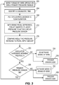
Fig. 3 is a flow diagram illustrating steps of a method according to one aspect of the invention. -
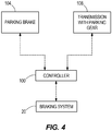
Fig. 4 is a schematic view of a vehicle including the braking system ofFig. 1 . - The
braking system 20 ofFig. 1 includes amaster cylinder 24 having an input side coupled with aninput rod 25 to abrake pedal 28 to pressurize hydraulic fluid therein. Themaster cylinder 24 includes a first piston 261 that is coupled to thebrake pedal 28 to move directly therewith. The first piston 261 pressurizes hydraulic fluid in a first chamber of themaster cylinder 24 to be output from the first chamber at a first outlet 401. A second piston 262 of themaster cylinder 24 can be moved under the influence of fluid pressurized in the first chamber by the first piston 261, without the second piston 262 having any direct connection to the first piston 261 or thebrake pedal 28. The second piston 261 pressurizes hydraulic fluid in a second chamber of themaster cylinder 24 to be output from the second chamber at a second outlet 402. Afluid reservoir 32 is in fluid communication with the first and second chambers of themaster cylinder 24 until thebrake pedal 28 is initially actuated, at which time the pistons 261, 262 block off the master cylinder chambers from thereservoir 32. Apedal travel sensor 36 is coupled to thebrake pedal 28 and is operable to detect an amount of travel of thebrake pedal 28, so that a corresponding signal can be sent to a controller 100 (Fig. 4 ). Thecontroller 100 can be a computer electrically coupled with each sensor and each electrically-operable valve of thebraking system 20, to send signals thereto and/or receive signals therefrom to establish communication and control necessary to operate thebraking system 20. As shown in the vehicle schematic ofFig. 4 , thecontroller 100 can further be coupled to one or both of aparking brake 104 and a transmission having aparking gear 108. Theparking brake 104 can have an active position that locks out the vehicle from being driven (e.g., by mechanically locking at least one wheel of the vehicle against rotation, thus preventing movement of the vehicle under its own power). Thetransmission 108 can be a conventional automatic multi-speed transmission or another type of transmission that has a selectable parking gear that can be actuated to a position that locks out the vehicle from being driven (e.g., by mechanically locking an output of the transmission against rotation, thus preventing movement of the vehicle under its own power). Either one or both of theparking brake 104 or thetransmission 108 can define an actively- or positively-"parked" condition of the vehicle. - The dual outputs 401, 402 of the
master cylinder 24 are selectively in fluid communication with a first braking circuit and a second braking circuit, respectively. In the illustrated construction, each of the braking circuits includes a pair of brake devices or wheel cylinders WC operable to slow down the wheels of a vehicle on which thebraking system 20 is provided. The wheel cylinders WC of a particular circuit can be associated with a set of front vehicle wheels, a set of rear vehicle wheels, or a set of diagonal vehicle wheels. Each braking circuit includes aninlet valve 44 and anoutlet valve 48 associated with each respective wheel cylinder WC. Theinlet valves 44 are normally-open and can be electrically closed by thecontroller 100 to stop or limit pressurized hydraulic fluid supplied to the wheel cylinder WC. Theoutlet valves 48 are normally-closed and can be electrically opened by thecontroller 100 to relieve pressurized hydraulic fluid at the wheel cylinder WC, to thereservoir 32. Each of the master cylinder outlets 401, 402 is coupled to one of the braking circuits through a normally-open isolation valve 521, 522. Each of the isolation valves 521, 522 is operable to be closed by thecontroller 100 to fluidly separate or isolate themaster cylinder 24, and thus thebrake pedal 28, from the braking circuits having the wheel cylinders WC. - Although the
master cylinder 24 is capable of providing mechanical braking from thebrake pedal 28 to the wheel cylinders WC of the two braking circuits, thesystem 20 can be provided with an alternate or auxiliary device, separate from thebrake pedal 28 and referred to herein as abrake pressure generator 60, for generating hydraulic fluid pressure to the wheel cylinders WC for the requisite braking need. Thebrake pressure generator 60 can include a plunger orpiston 62 drivable in a cylinder by an actuator such as anelectric motor 64 operated by thecontroller 100. As such, thebrake pressure generator 60 is operable to drive pressurized hydraulic fluid to the wheel cylinders WC of the first and second braking circuits. For example, anoutlet 68 of thebrake pressure generator 60 can be coupled, in parallel, to the first and second braking circuits through respective apply pressure control valves 721, 722. Each of the apply pressure control valves 721, 722 can be a controller-modulated solenoid valve (e.g., having a range of open positions, or receiving a pulse-width modulation signal to achieve a similar effect) operable to control the pressure supplied from thebrake pressure generator 60 to the wheel cylinders WC of the given braking circuit. The apply pressure control valves 721, 722 can be coupled to respective brake fluid supply lines or passages, each of which extends between one of the isolation valves 521, 522 and therespective inlet valves 44 of the braking circuit. One ormore pressure sensors 76 can be positioned along the fluid path between the brakepressure generator outlet 68 and therespective inlet valves 44 and operable to report the fluid pressure to thecontroller 100. Thepressure sensor 76 can be referred to as an "active circuit" pressure sensor as it senses and reports the fluid pressure in the passage(s) coupled to the wheel cylinders WC, as contrasted with fluid pressure in themaster cylinder 24 or a simulator circuit, which are not part of an active braking circuit during brake-by-wire operation. Additional sensors may be provided to monitor parameters of thepiston 62 and/or theelectric motor 64, and may include any one or more of: linear or angular position, electrical current, electrical voltage, force, torque, or temperature. - In addition to the active braking components in the
system 20, a simulator circuit is provided in fluid communication with the output side of themaster cylinder 24. The simulator circuit is provided upstream of the isolation valves 521, 522, meaning the side nearer the master cylinder and remote from the braking circuits so that the simulator circuit is kept in fluid communication with themaster cylinder 24 when the isolation valves 521, 522 are closed. The simulator circuit includes apedal feel simulator 80 coupled to an outlet of the master cylinder 24 (e.g., the first outlet 401) through aswitchable simulator valve 84. Thesimulator valve 84 can be a normally-closed switchable solenoid valve operable to be opened by thecontroller 100 to establish fluid communication between the master cylinder outlet 401 and thepedal feel simulator 80. When thesimulator valve 84 is open, fluid pushed out of the master cylinder chamber through the outlet 401 is passed into thepedal feel simulator 80, which has a biasing mechanism that provides a feedback force to thebrake pedal 28. Thus, the simulator circuit mimics the feel of actuating the wheel cylinders WC when in fact thebrake pedal 28 is decoupled by the isolation valves 521, 522 from the actual braking pressure activating the wheel cylinders WC in the braking circuits. A pressure sensor, referred to herein as theprimary pressure sensor 88, is provided in fluid communication with themaster cylinder 24 to detect a fluid pressure generated in one of the master cylinder chambers. For example, theprimary pressure sensor 88 can be coupled to the second master cylinder outlet 402, upstream of the isolation valve 522. Theprimary pressure sensor 88 is operable to generate a braking request signal responsive to an input force from thebrake pedal 28. - Though not conducive to labeling in
Fig. 1 , it will be understood that each braking circuit extends from one of the isolation valves 521, 522 to the respective wheel cylinder(s) WC, and further includes the passages connecting to thebrake pressure generator 60, and the respective passages connecting to thefluid reservoir 32, while the simulator circuit is a separate circuit, not part of either of the braking circuits, since fluid in the simulator circuit is not conveyed to contribute to actual braking force at the wheel cylinders WC. - During normal operation of the
braking system 20, thebrake pedal 28 is decoupled from the wheel cylinders WC so that braking occurs fully in a primary brake-by-wire mode. When the driver depresses thebrake pedal 28, the isolation valves 521, 522 are actuated to a closed position (opposite the position shown inFig. 1 ) so that themaster cylinder 24 and the simulator circuit are cut-off or isolated from the braking circuits. Thesimulator valve 84 is also switched open by thecontroller 100 upon initial actuation of thebrake pedal 28, which can be detected by thepedal travel sensor 36. A pressure increase occurs in the second master cylinder chamber and between the second outlet 402 and the second isolation valve 522 since thepedal 28 urges the pistons 261, 262 to move toward the closed-off second isolation valve 522. The pressure increase is measured or detected by theprimary pressure sensor 88 and conveyed as a signal to thecontroller 100, which is programmed to use the information to determine the degree of actuation of thebrake pressure generator 60 to achieve a target brake force as requested by the driver's actuation of thebrake pedal 28. In some constructions, an output of thepedal travel sensor 36 is also considered by the controller along with theprimary pressure sensor 88 in quantifying the driver's braking request. Thecontroller 100 can also provide variable manipulation of the apply pressure control valves 721, 722 to achieve a desired brake force and brake force balance in the braking circuits. Thus, in the illustrated construction, themotor 64 is energized as programmed by thecontroller 100 to drive thepiston 62 forward in the cylinder toward theoutlet 68 so that fluid pressure is generated at the outlet and hydraulic fluid is moved from thebrake pressure generator 60 toward the wheel cylinders WC, which may include one or more pistons incorporated into brake calipers so that the hydraulic fluid from thegenerator 60 causes the wheel cylinders WC to squeeze onto a brake disc. As can be interpreted from this description, thebrake pressure generator 60 is controlled to achieve an amount of braking according to the driver's request, which is interpreted at least in part by theprimary pressure sensor 88, which continuously measures how hard the driver is applying pressure to thebrake pedal 28. In the event of a component failure or abnormality, thebraking system 20 is designed to provide a back-up mode of operation in which the isolation valves 521, 522 return to their normally-open positions to allow thebrake pedal 28 to actuate the wheel cylinders WC through themaster cylinder 24. However, the invention provides a diagnostic routine to check the operational status of the components in the simulator circuit, which enable thesystem 20 to maintain brake-by-wire operation. - At a diagnostic time when one or both of the
parking brake 104 is activated and the parking gear of thetransmission 108 is activated and the driver is depressing thebrake pedal 28, thecontroller 100 is programmed to put the system into a diagnostic configuration as shown inFig. 1 and carry out a diagnostic routine. For the diagnostic configuration, thecontroller 100 is programmed to open (i.e., not actuate closed) the first isolation valve 521 and thecontroller 100 is programmed to actuate the first apply pressure control valve 721 to open. The second isolation valve 522 can also be left open, but the second apply pressure control valve 722 is closed to provide a point of fluid separation between the second master cylinder outlet 402 and the two connected wheel cylinders WC on one side and thepressure sensor 76 and thebrake pressure generator 60 on the other side. The open first isolation valve 521 places the simulator circuit, in particular thesimulator valve 84 and thepedal feel simulator 80, in fluid communication with the corresponding braking circuit. However, theinlet valves 44 that are coupled to the master cylinder outlet 401 through the first isolation valve 521 are actuated closed to block fluid communication between themaster cylinder 24 and the corresponding wheel cylinders WC of the first braking circuit. Thus, a diagnostic circuit, excluding the wheel cylinders WC blocked by theclosed inlet valves 44, is established between the simulator circuit and thepressure sensor 76 that is positioned in the braking circuit, in particular the pressure sensor 76 (differentiated from theprimary pressure sensor 88 as being the "secondary" or "active circuit" pressure sensor) positioned between the brakepressure generator outlet 68 and the apply pressure control valves 721, 722. Thebrake pressure generator 60 can also be included in the diagnostic circuit, although themotor 64 may be left idle during the diagnostic routine. - During the diagnostic time, the
controller 100 is programmed to maintain thesimulator valve 84 and the first apply pressure control valve 721 open. With thesystem 20 put into the diagnostic configuration as described above and shown inFig. 1 , thecontroller 100 can evaluate a relationship between the input to thebrake pedal 28 and the observed fluid pressure that is generated at the master cylinder output side, as measured by thesecondary pressure sensor 76. During the diagnostic routine, brake pressure is exerted from thebrake pedal 28, through the second master cylinder outlet 402, through the second isolation valve 522 and through theinlet valves 44 to the associated wheel cylinders WC. This not only ensures maintaining driver-applied braking, but further avoids a "hard pedal" condition if thesimulator valve 84 fails to open when actuated. - In observing the relationship between brake pedal input and the resulting increase in fluid pressure, the information observed by the
controller 100 is represented by the graph ofFig. 2 . The x-axis represents brake pedal input (correlated here as fluid volume), while the y-axis represents the sensed fluid pressure, in other words, the output of thesecondary pressure sensor 76. Monitoring the brake pedal input for the diagnostic routine can include monitoring an output of thepedal travel sensor 36, and the controller may optionally convert the linear or positional data to fluid volume date based on known parameters of themaster cylinder 24.Fig. 2 illustrates two exemplary plots or traces that may be observed by thecontroller 100 during the diagnostic routine. Starting on the left, if thesimulator valve 84 is stuck closed and does not open when actuated, the pressure in the diagnostic circuit established between the first master cylinder outlet 401 and the simulator circuit will rise relatively rapidly, alongplot 1, with a relatively small amount of brake pedal input. If thesimulator valve 84 opens as normal, and thepedal feel simulator 80 is in good working condition, the pressure increases according to brake pedal input alongplot 2 on the right. By observing the relationship between brake pedal input and the resulting pressure increase during the diagnostic routine as shown inFig. 2 , the controller can determine whether the simulator circuit is operable to properly receive fluid and provide pedal feedback for brake-by-wire operation. When thecontroller 100 finds that the pressure is within a predetermined tolerance range of an expected pressure value P1 (e.g., P2>P1>P3 for a given brake pedal input V1) on the normal plot, this indicates a good check or satisfactory condition. When the results of the diagnostic routine finds that the pressure is at least a predetermined amount higher than the expected pressure value P1 (e.g., above P2 for the given brake pedal input V1), this indicates a "hard pedal" condition. In other words, the pressure rises significantly faster than expected for a normally-functioning system as thepiston 62 is stroked, and thecontroller 100 predicts or determines the occurrence of hard pedal condition. Hard pedal refers to the circumstance when brake pedal travel is far less than a design amount for a given target circuit pressure. Thecontroller 100 may also be programmed to identify a fluid leak if during the diagnostic routine, the fluid pressure does not increase within a predetermined tolerance range of the expected pressure value P1 (e.g., pressure does not exceed P3 for the given brake pedal input V1). This is indicative of a "soft pedal" condition that leads to an excessive amount of brake pedal travel, beyond a design amount, for a given a braking pressure. The diagnostic routine may require at least a predetermined minimum brake pedal input amount (e.g., 0.15 cm3). - The
controller 100 can be programmed to conduct the diagnostic routine in response to detecting an abnormal value from theprimary pressure sensor 88, or thecontroller 100 may be programmed to conduct the diagnostic routine upon each identification of the prerequisite factors for the diagnostic time (e.g., each time the vehicle is actively "parked" and the driver is depressing thebrake pedal 28 at least a predetermined amount), or thecontroller 100 may be programmed to conduct the diagnostic routine on a less frequent basis, such as a single time during a period of continuous vehicle operation (e.g., first opportunity). - The diagnostic routine serves as a hardware check that allows the
controller 100 to determine whether there is any mechanical failure of the simulator circuit (e.g.,simulator valve 84 not opening,pedal feel simulator 80 stuck and not receiving fluid). In the case of a mechanical failure in the simulator circuit, thebraking system 20 may not be enabled to perform brake-by-wire braking, since the simulator circuit is required to accept the fluid from themaster cylinder 24 when the braking pressure comes from a source other than themaster cylinder 24. However, when thecontroller 100 can determine based on the diagnostic routine that there is nothing mechanically wrong with the simulator circuit, thesystem 20 can be operated in brake-by-wire operation. If thecontroller 100 has determined that theprimary pressure sensor 88 is reporting abnormal values and cannot be relied upon to generate the braking request signal for brake-by-wire operation, thebraking system 20 transitions to a secondary brake-by-wire mode in which the braking request signal is generated by thepedal travel sensor 36, assuming that the diagnostic routine has indicated no physical failure in the simulator circuit. This method of operation enables thebraking system 20 to perform in a more sophisticated manner and achieve better performance, by retaining brake-by-wire operation when theprimary pressure sensor 88 fails, as long as the operability of the simulator circuit hardware is confirmed in the diagnostic routine. - The process carried out by the program of the
controller 100 as described above is visually represented in the flow diagram ofFig. 3 . Atstep 200, thecontroller 100 operates thebraking system 20 in a first mode, which is the normal or primary brake-by-wire mode in which the braking force (i.e., hydraulic fluid pressure) to the wheel cylinders WC is produced by thebrake pressure generator 60, not themaster cylinder 24, in proportion to the driver's demand as manifested by the fluid pressure sensed by theprimary pressure sensor 88. The apply pressure control valves 721, 722 may open and close as required to modulate the pressure to the two braking circuits. Duringstep 200, thesimulator valve 84 is open and the two isolation valves 521, 522 are closed. Although the primary brake-by-wire mode is the default mode of thebraking system 20, the system may not actively function in this mode prior to running the diagnostic routine. Atstep 204, thecontroller 100 identifies the diagnostic time as described above. Examples of the manner in which thecontroller 100 detects the abnormality have been described above. Atstep 208, thecontroller 100 puts thebraking system 20 into the diagnostic configuration. This includes controlling the system valves as shown inFig. 1 to establish a diagnostic circuit (not for braking) that includes the brake pressure generator, the simulator circuit, and thesecondary pressure sensor 76. The diagnostic circuit utilizes portions of the first braking circuit, while the second braking circuit is maintained fluidly separate. In the diagnostic configuration, thesimulator valve 84 is actuated to open. Thebraking system 20, in particular the program of thecontroller 100, then carries out the diagnostic routine to determine whether there is any fault with the mechanical components, such as those of the simulator circuit that normally enable fluid to be received from themaster cylinder 24 during brake-by-wire operation. - At
step 212, fluid is conveyed to thesecondary pressure sensor 76 by actuation of thebrake pedal 28, which is also in fluid communication with the simulator circuit. Although it is normal to establish fluid connection between the output side of themaster cylinder 24 and the simulator circuit in a brake-by-wire system, the diagnostic configuration is unique in coupling the output side of themaster cylinder 24 and the simulator circuit with the portion of the circuit that is normally the active brake-by-wire circuit. This is done so that thesecondary pressure sensor 76 can be used for diagnosis. Atstep 216, thecontroller 100 is programmed to compare the resulting pressure increase, as measured by thesecondary pressure sensor 76, to the brake pedal input. Thus, thecontroller 100 can observe the relationship between actuation amount of thebrake pedal 28 and the resulting fluid pressure increase and can compare this data to data or values stored in a memory of the controller 100 (e.g., the data corresponding toFig. 2 ) to determine if the simulator hardware is in proper working condition atstep 220. As described above, this can include determining whether a "hard pedal" condition occurs. When the simulator hardware is found to be in non-working condition resulting in the hard pedal condition, thepedal feel simulator 80 is prevented from receiving fluid in the designed manner, such as thepedal feel simulator 80 having an internal component (e.g., a spring) being stuck or thesimulator valve 84 being stuck closed. As such, thecontroller 100 de-activates brake-by-wire operation atstep 224. For this mode of operation, the system valves default to their normally-biased positions. Thebraking system 20 is then operable in a "coupled" or "direct" braking mode in which fluid pressure at themaster cylinder 24 is propagated to the wheel cylinders WC, and thebrake pressure generator 60 is left idle. In addition to transitioning out of the primary brake-by-wire mode, the controller can also trigger and store an error code atstep 236 when a malfunction of the simulator hardware is determined atstep 220. - When the
controller 100 determines that the simulator hardware is working properly, the process continues to step 228 whereby the state of theprimary pressure sensor 88 can optionally be confirmed. It is noted that the state of theprimary pressure sensor 88 can be identified (e.g., identification of an abnormal value) in advance of the diagnostic time, and in some cases may trigger the diagnostic routine. If the simulator hardware is checked to be OK and theprimary pressure sensor 88 has not reported abnormal values, the process returns to normal primary mode brake-by-wire operation atstep 200. On the other hand, when the simulator hardware is checked to be OK and theprimary pressure sensor 88 has reported abnormal values, thecontroller 100 atstep 232 is programmed to activate a secondary brake-by-wire mode. The controller can also trigger and store an error code atstep 238 when the primary pressure sensor output is deemed abnormal. Rather than a generic "system fault" error, the error codes ofsteps primary pressure sensor 88, was confirmed to be in working order or not. Thus, a service technician can more readily identify the source of the problem and more conveniently provide an appropriate repair or replacement. Optionally, the error code may be displayed to the driver in an instrument panel of the vehicle, either in a generic or specific format. - When the diagnostic routine proceeds to step 232 after confirming proper operation of the simulator hardware, the
system 20 commences brake-by-wire operation in the secondary mode. In this mode, brake pedal actuation is detected by thepedal travel sensor 36, and the driver isolation valves 521, 522 are actuated to close and thesimulator isolation valve 84 is actuated to open. As pedal feedback is provided by thepedal feel simulator 80, a braking request of the driver is sensed and reported to thecontroller 100 by a sensor (e.g., the pedal travel sensor 36) other than the primary orsecondary pressure sensors brake pressure generator 60 and applied to the corresponding wheel cylinders WC through the respective apply pressure control valves 721,722.
Claims (20)
- A vehicle braking system comprising:a master cylinder having an input side coupled to a brake pedal and an output side configured to provide a master cylinder output via a first outlet and a second outlet,a first braking circuit having at least one wheel cylinder coupled to the first master cylinder outlet via a first normally-open isolation valve and a first normally-open inlet valve;a second braking circuit having at least one wheel cylinder coupled to the second master cylinder outlet via a second normally-open isolation valve and a second normally-open inlet valve;a brake pressure generator separate from the brake pedal;a simulator circuit including a pedal feel simulator coupled to the first master cylinder outlet through a switchable simulator valve, the simulator circuit being isolated from the first braking circuit when the first isolation valve is in a closed position, wherein the pedal feel simulator provides a reaction force to the brake pedal when the switchable simulator valve is in an open position;a pressure sensor positioned in the first braking circuit between the first isolation valve and an output of the brake pressure generator; characterised bya controller programmed to, at a designated diagnostic time when the brake pedal is depressed to generate a brake pedal input while the vehicle is locked out from being driven by one or both of a parking brake and a transmission parking gear, open the simulator valve without closing the first isolation valve to place the pedal feel simulator in fluid communication with the pressure sensor of the first braking circuit, and to observe with the pressure sensor an increase in brake fluid pressure resulting from the brake pedal input,wherein the controller is further programmed to check whether the relationship between the observed brake fluid pressure increase and the brake pedal input is within a predetermined acceptable range for continued operation of a brake-by-wire vehicle braking mode in which the master cylinder is coupled to the simulator circuit and decoupled from the first and second braking circuits, while brake fluid pressure to the wheel cylinders of the first and second braking circuits is provided solely by the brake pressure generator.
- The vehicle braking system of claim 1, wherein the controller is programmed to switch from brake-by-wire mode to a secondary mechanical push-through back-up in which the master cylinder output side is coupled to the first and second braking circuits rather than the pedal feel simulator in response to the determination by the controller that the relationship between the observed brake fluid pressure increase and the brake pedal input is not within the predetermined acceptable range.
- The vehicle braking system of claim 1, wherein at the designated diagnostic time, the pedal feel simulator is in fluid communication with an output of the brake pressure generator.
- The vehicle braking system of claim 3, wherein the pressure sensor is positioned between the output of the brake pressure generator and a normally-closed apply pressure control valve.
- The vehicle braking system of claim 4, wherein the apply pressure control valve is a controller-modulated solenoid valve that modulates a connection between the output of the brake pressure generator and the at least one wheel cylinder of the first braking circuit, and wherein the controller is programmed to hold the apply pressure control valve in an open position to establish fluid communication between the simulator circuit and the pressure sensor.
- The vehicle braking system of claim 1, wherein the controller is further programmed to close the normally-open inlet valve of the first braking circuit during the designated diagnostic time to prevent actuation of the at least one wheel cylinder of the first braking circuit.
- The vehicle braking system of claim 1, further comprising an apply pressure control valve positioned between an output of the brake pressure generator and the at least one wheel cylinder of the second braking circuit, wherein the controller is programmed to keep the apply pressure control valve closed during the designated diagnostic time.
- The vehicle braking system of claim 1, further comprising a sensor operable to send a signal to the controller confirming either that a parking brake is engaged, or that the transmission parking gear is engaged.
- The vehicle braking system of claim 1, wherein the controller is programmed to store an error code identifying a simulator circuit leak when the observed brake fluid pressure increase is below the predetermined acceptable range for the brake pedal input.
- The vehicle braking system of claim 1, wherein the controller is programmed to store an error code identifying a stuck pedal feel simulator or simulator valve when the observed brake fluid pressure increase is above the predetermined range for the brake pedal input.
- The vehicle braking system of claim 1, wherein the pressure sensor is separate from a primary pressure sensor used by the controller to generate a control signal for the brake pressure generator during a primary brake-by-wire mode of operation, and wherein controller is programmed to trigger the designated diagnostic time in response to identifying an abnormal value from the primary pressure sensor, and wherein the controller is programmed to transition to a secondary brake-by-wire mode using a pedal travel sensor to generate the control signal for the brake pressure generator when the relationship between the observed brake fluid pressure increase and the brake pedal input is within the predetermined acceptable range such that it is determined that the pedal feel simulator and the simulator valve are in working order and the cause of the abnormal value from the primary pressure sensor is a malfunction of the primary pressure sensor.
- A method of operating a vehicle braking system utilizing a controller, the method comprising:operating in a primary brake-by-wire braking mode including:receiving an input from a brake pedal at an input side of a master cylinder and providing a master cylinder output corresponding to the brake pedal input at an output side of the master cylinder output,closing, by a controller signal, a first normally-open isolation valve to isolate the output side of the master cylinder from a first braking circuit having at least one wheel cylinder,sending a controller signal to a switchable simulator valve to open a fluid connection between the master cylinder output side and a simulator circuit including a pedal feel simulator to provide a reaction force to the brake pedal,generating a braking request signal with a primary pressure sensor responsive to the input from the brake pedal, the braking request signal being sent to the controller, anddriving a brake pressure generator of the first braking circuit with the controller responsive to the braking request signal to achieve braking at the at least one wheel cylinder, the brake pressure generator being separate from the brake pedal; characterised bysending a controller signal, at a designated diagnostic time when the brake pedal is depressed to generate a brake pedal input while the vehicle is locked out from being driven by one or both of a parking brake and a transmission parking gear, to open the simulator valve without closing the first isolation valve to place the simulator circuit in fluid communication with a secondary pressure sensor of the first braking circuit;observing with the secondary pressure sensor an increase in brake fluid pressure resulting from the brake pedal input, and reporting the observed increase in brake fluid pressure to the controller; anddetermining with the controller, whether the relationship between the observed brake fluid pressure increase and the brake pedal input is within a predetermined acceptable range for continued operation of the primary brake-by-wire braking mode.
- The method of claim 12, wherein the brake pressure generator outputs brake pressure to the at least one wheel cylinder of the first braking circuit through a first controller-modulated apply pressure control valve in the primary brake-by-wire braking mode, the method further comprising maintaining the first apply pressure control valve in an open position during the designated diagnostic time to establish fluid communication between the simulator circuit and the secondary pressure sensor.
- The method of claim 12, further comprising detecting either that the parking brake is engaged, or that the transmission parking gear is engaged, and sending a corresponding signal to the controller.
- The method of claim 12, further comprising sending a signal from the controller to close a normally-open inlet valve between the brake pressure generator and the at least one wheel cylinder of the first braking circuit during the designated diagnostic time to prevent actuation of the at least one wheel cylinder of the first braking circuit.
- The method of claim 15, wherein during the designated diagnostic time, brake pressure is supplied from the output side of the master cylinder to at least one wheel cylinder of a second braking circuit isolated from the first braking circuit.
- The method of claim 12, wherein the primary pressure sensor detects fluid pressure at an outlet of the master cylinder coupled to a second chamber pressurized by a second piston remote from a first chamber having a first piston coupled to the brake pedal, and wherein the pedal feel simulator is actuated from an outlet of the master cylinder coupled to the first chamber.
- The method of claim 12, wherein the designated diagnostic time is triggered by the controller identifying an abnormal value for the braking request signal from the primary pressure sensor.
- The method of claim 12, further comprising automatically switching via the controller from the primary brake-by-wire mode to a secondary brake-by-wire mode that utilizes a brake pedal travel sensor as an input for the brake pressure generator in response to determining that the relationship between the observed brake fluid pressure increase and the brake pedal input is within the predetermined acceptable range such that it is confirmed that the pedal feel simulator and the simulator valve are in working order.
- The method of claim 12, further comprising switching from the primary brake-by-wire mode to a secondary mechanical push-through back-up mode that utilizes the brake pedal without using the brake pressure generator or the pedal feel simulator in response to determining that the relationship between the observed brake fluid pressure increase and the brake pedal input is outside the predetermined acceptable range.
Applications Claiming Priority (1)
| Application Number | Priority Date | Filing Date | Title |
|---|---|---|---|
| US15/373,419 US10046748B2 (en) | 2016-12-08 | 2016-12-08 | Vehicle having brake system and method of operating |
Publications (2)
| Publication Number | Publication Date |
|---|---|
| EP3333028A1 EP3333028A1 (en) | 2018-06-13 |
| EP3333028B1 true EP3333028B1 (en) | 2019-07-24 |
Family
ID=60051381
Family Applications (1)
| Application Number | Title | Priority Date | Filing Date |
|---|---|---|---|
| EP17195171.8A Active EP3333028B1 (en) | 2016-12-08 | 2017-10-06 | A vehicle braking system and a method of operating a vehicle braking system |
Country Status (2)
| Country | Link |
|---|---|
| US (1) | US10046748B2 (en) |
| EP (1) | EP3333028B1 (en) |
Families Citing this family (13)
| Publication number | Priority date | Publication date | Assignee | Title |
|---|---|---|---|---|
| JP6512148B2 (en) * | 2016-03-25 | 2019-05-15 | 株式会社アドヴィックス | Vehicle braking system |
| JP7133323B2 (en) * | 2017-03-08 | 2022-09-08 | ハーレー-ダビッドソン・モーター・カンパニー・グループ・エルエルシー | Systems and methods for detecting stuck valves |
| JP6939273B2 (en) * | 2017-08-31 | 2021-09-22 | 株式会社アドヴィックス | Brake control device |
| JP6898884B2 (en) * | 2018-05-15 | 2021-07-07 | 日立Astemo株式会社 | Brake control device and abnormality detection method for brake control device |
| DE102019123351A1 (en) * | 2019-08-30 | 2021-03-04 | Lsp Innovative Automotive Systems Gmbh | Braking device, in particular for electrically powered motor vehicles |
| DE102019215288A1 (en) * | 2019-10-04 | 2021-04-08 | Robert Bosch Gmbh | Method for controlling an electronically slip-regulated external power brake system, in particular for a motor vehicle and electronically slip-regulated external power brake system, in particular for a motor vehicle |
| US12103509B2 (en) * | 2020-06-12 | 2024-10-01 | Robert Bosch Gmbh | Tracking hydraulic pressure support events in a vehicle |
| DE102020212413A1 (en) * | 2020-09-30 | 2022-03-31 | Robert Bosch Gesellschaft mit beschränkter Haftung | Service braking with a hydraulic multi-circuit externally powered vehicle brake system |
| US11932213B2 (en) * | 2021-03-26 | 2024-03-19 | Toyota Research Institute, Inc. | System and method for controlling one or more brakes of a vehicle |
| CN113335259B (en) * | 2021-07-22 | 2022-06-21 | 中国第一汽车股份有限公司 | Brake system power-on detection method, device, equipment and storage medium |
| CN113997918B (en) * | 2021-11-24 | 2023-11-21 | 吉林东光奥威汽车制动系统有限公司 | Center part of electronic brake booster capable of being mechanically and fully decoupled |
| CN114987410A (en) * | 2022-06-15 | 2022-09-02 | 麦格纳卫蓝新能源汽车技术(镇江)有限公司 | A multifunctional pedal control system |
| CN115891959A (en) * | 2022-12-30 | 2023-04-04 | 上海拿森汽车电子有限公司 | A control method and system for a vehicle electronically controlled booster, and a vehicle |
Family Cites Families (18)
| Publication number | Priority date | Publication date | Assignee | Title |
|---|---|---|---|---|
| JP2532059B2 (en) | 1985-09-13 | 1996-09-11 | 日産自動車株式会社 | Vehicle suspension control device |
| EP0420949B1 (en) | 1989-04-22 | 1994-01-12 | ITT Automotive Europe GmbH | Skid-controlled brake installation, in particular one for motor vehicles |
| JP3965218B2 (en) | 1996-03-29 | 2007-08-29 | 日産自動車株式会社 | Vehicle brake control system |
| JP3564960B2 (en) * | 1997-08-12 | 2004-09-15 | トヨタ自動車株式会社 | Brake fluid pressure control device |
| JP3747617B2 (en) | 1998-03-10 | 2006-02-22 | 日産自動車株式会社 | Brake assist system |
| JPH11301462A (en) | 1998-04-16 | 1999-11-02 | Toyota Motor Corp | Abnormality judgment device for vehicle braking force control device |
| GB2345322B (en) | 1998-12-31 | 2002-12-11 | Lucas Ind Plc | Driver warning of braking malfunction in electro-hydraulic (EHB) braking systems |
| JP4506793B2 (en) | 2007-07-17 | 2010-07-21 | トヨタ自動車株式会社 | Brake control device |
| CN201534540U (en) | 2009-10-14 | 2010-07-28 | 廖竹铭 | Automotive intelligent brake apparatus |
| DE112011100209T5 (en) * | 2010-01-08 | 2012-10-31 | Honda Motor Co., Ltd. | Braking device and braking process |
| JP2012096617A (en) | 2010-10-29 | 2012-05-24 | Hitachi Automotive Systems Ltd | Brake apparatus |
| CN103260968B (en) | 2010-12-23 | 2015-08-26 | 本田技研工业株式会社 | Braking device for vehicle |
| DE102012201535A1 (en) | 2011-04-19 | 2012-10-25 | Continental Teves Ag & Co. Ohg | Brake system for motor vehicles and method for testing a brake system |
| DE102012205859A1 (en) | 2011-04-19 | 2012-10-25 | Continental Teves Ag & Co. Ohg | Brake system for motor vehicles and method for operating a brake system |
| JP2013028273A (en) | 2011-07-28 | 2013-02-07 | Hitachi Automotive Systems Ltd | Electric booster |
| DE102013203594A1 (en) | 2012-03-06 | 2013-09-12 | Continental Teves Ag & Co. Ohg | Method for operating a brake system for motor vehicles and brake system |
| GB2504820B (en) | 2012-06-07 | 2016-12-28 | Jaguar Land Rover Ltd | Improvements in vehicle steering |
| KR102473927B1 (en) * | 2015-10-19 | 2022-12-06 | 에이치엘만도 주식회사 | Diagnosis method of Electric brake system |
-
2016
- 2016-12-08 US US15/373,419 patent/US10046748B2/en active Active
-
2017
- 2017-10-06 EP EP17195171.8A patent/EP3333028B1/en active Active
Non-Patent Citations (1)
| Title |
|---|
| None * |
Also Published As
| Publication number | Publication date |
|---|---|
| US20180162339A1 (en) | 2018-06-14 |
| EP3333028A1 (en) | 2018-06-13 |
| US10046748B2 (en) | 2018-08-14 |
Similar Documents
| Publication | Publication Date | Title |
|---|---|---|
| US10046748B2 (en) | Vehicle having brake system and method of operating | |
| EP3333031B1 (en) | Brake system and method of operating | |
| EP3333033B1 (en) | Vehicle having brake system and method of operating | |
| EP3333029B1 (en) | Vehicle having brake system and method of operating | |
| KR102479868B1 (en) | Braking system with two pressure sources and how to operate the braking system with two pressure sources | |
| US12570258B2 (en) | Fail-safe valve unit, electronically controllable pneumatic brake system, method for operating a brake system | |
| US11565681B2 (en) | Method for testing a pressure-medium-operated electronic brake system | |
| CN112585044A (en) | Haptic feedback for decoupled braking systems | |
| US12594917B2 (en) | Failsafe valve unit, electronically controllable pneumatic brake system, vehicle, and method | |
| US6089678A (en) | Hydraulic braking systems for vehicles | |
| KR20230053638A (en) | Method for checking availability of hydraulic fallback level in electronic slip controlled power brake system, electronic control device for electronic slip controlled power brake system and electronic slip controlled power brake system having electronic control device | |
| EP1671863B1 (en) | Electronic braking device | |
| CN103140397B (en) | Braking system and method of operation thereof | |
| KR20220119160A (en) | Vacuum boost braking system with redundancy | |
| KR20240157912A (en) | Electronic brake system and the control method therefor | |
| US6550870B1 (en) | Parking brake control | |
| KR102858632B1 (en) | Control method for an electronically slip-controlled power brake system and power brake system | |
| US20110074207A1 (en) | Brake device | |
| CN113905935B (en) | Method and device for operating a hydraulic brake system, brake system and vehicle | |
| JP5438563B2 (en) | Brake control device | |
| JP4612454B2 (en) | Brake control device | |
| US12630137B2 (en) | Method and device for operating a hydraulic braking system, braking system and vehicle | |
| WO2025058774A1 (en) | Redundant power supply architecture for two independent boardnets with cross connection to support supply from only one power input for electronic brake systems | |
| CN117751063A (en) | Method for checking the contact of circuit branches associated with each other of separate brake circuits of a brake-assist system, which has two actuator units in contact with each other in a pressure medium-conducting manner, for brake pressure generation and brake pressure regulation, in particular for motor vehicles, for electronic slip regulation | |
| WO2021026048A2 (en) | Complementary brake actuation retrofit |
Legal Events
| Date | Code | Title | Description |
|---|---|---|---|
| PUAI | Public reference made under article 153(3) epc to a published international application that has entered the european phase |
Free format text: ORIGINAL CODE: 0009012 |
|
| STAA | Information on the status of an ep patent application or granted ep patent |
Free format text: STATUS: THE APPLICATION HAS BEEN PUBLISHED |
|
| AK | Designated contracting states |
Kind code of ref document: A1 Designated state(s): AL AT BE BG CH CY CZ DE DK EE ES FI FR GB GR HR HU IE IS IT LI LT LU LV MC MK MT NL NO PL PT RO RS SE SI SK SM TR |
|
| AX | Request for extension of the european patent |
Extension state: BA ME |
|
| STAA | Information on the status of an ep patent application or granted ep patent |
Free format text: STATUS: REQUEST FOR EXAMINATION WAS MADE |
|
| 17P | Request for examination filed |
Effective date: 20181213 |
|
| RBV | Designated contracting states (corrected) |
Designated state(s): AL AT BE BG CH CY CZ DE DK EE ES FI FR GB GR HR HU IE IS IT LI LT LU LV MC MK MT NL NO PL PT RO RS SE SI SK SM TR |
|
| GRAP | Despatch of communication of intention to grant a patent |
Free format text: ORIGINAL CODE: EPIDOSNIGR1 |
|
| STAA | Information on the status of an ep patent application or granted ep patent |
Free format text: STATUS: GRANT OF PATENT IS INTENDED |
|
| RIC1 | Information provided on ipc code assigned before grant |
Ipc: B60T 8/40 20060101AFI20190116BHEP Ipc: B60T 17/22 20060101ALI20190116BHEP |
|
| INTG | Intention to grant announced |
Effective date: 20190215 |
|
| GRAS | Grant fee paid |
Free format text: ORIGINAL CODE: EPIDOSNIGR3 |
|
| GRAA | (expected) grant |
Free format text: ORIGINAL CODE: 0009210 |
|
| STAA | Information on the status of an ep patent application or granted ep patent |
Free format text: STATUS: THE PATENT HAS BEEN GRANTED |
|
| AK | Designated contracting states |
Kind code of ref document: B1 Designated state(s): AL AT BE BG CH CY CZ DE DK EE ES FI FR GB GR HR HU IE IS IT LI LT LU LV MC MK MT NL NO PL PT RO RS SE SI SK SM TR |
|
| REG | Reference to a national code |
Ref country code: GB Ref legal event code: FG4D |
|
| REG | Reference to a national code |
Ref country code: CH Ref legal event code: EP |
|
| REG | Reference to a national code |
Ref country code: DE Ref legal event code: R096 Ref document number: 602017005506 Country of ref document: DE |
|
| REG | Reference to a national code |
Ref country code: AT Ref legal event code: REF Ref document number: 1157804 Country of ref document: AT Kind code of ref document: T Effective date: 20190815 |
|
| REG | Reference to a national code |
Ref country code: IE Ref legal event code: FG4D |
|
| REG | Reference to a national code |
Ref country code: NL Ref legal event code: MP Effective date: 20190724 |
|
| REG | Reference to a national code |
Ref country code: LT Ref legal event code: MG4D |
|
| REG | Reference to a national code |
Ref country code: AT Ref legal event code: MK05 Ref document number: 1157804 Country of ref document: AT Kind code of ref document: T Effective date: 20190724 |
|
| PG25 | Lapsed in a contracting state [announced via postgrant information from national office to epo] |
Ref country code: NO Free format text: LAPSE BECAUSE OF FAILURE TO SUBMIT A TRANSLATION OF THE DESCRIPTION OR TO PAY THE FEE WITHIN THE PRESCRIBED TIME-LIMIT Effective date: 20191024 Ref country code: SE Free format text: LAPSE BECAUSE OF FAILURE TO SUBMIT A TRANSLATION OF THE DESCRIPTION OR TO PAY THE FEE WITHIN THE PRESCRIBED TIME-LIMIT Effective date: 20190724 Ref country code: HR Free format text: LAPSE BECAUSE OF FAILURE TO SUBMIT A TRANSLATION OF THE DESCRIPTION OR TO PAY THE FEE WITHIN THE PRESCRIBED TIME-LIMIT Effective date: 20190724 Ref country code: LT Free format text: LAPSE BECAUSE OF FAILURE TO SUBMIT A TRANSLATION OF THE DESCRIPTION OR TO PAY THE FEE WITHIN THE PRESCRIBED TIME-LIMIT Effective date: 20190724 Ref country code: FI Free format text: LAPSE BECAUSE OF FAILURE TO SUBMIT A TRANSLATION OF THE DESCRIPTION OR TO PAY THE FEE WITHIN THE PRESCRIBED TIME-LIMIT Effective date: 20190724 Ref country code: AT Free format text: LAPSE BECAUSE OF FAILURE TO SUBMIT A TRANSLATION OF THE DESCRIPTION OR TO PAY THE FEE WITHIN THE PRESCRIBED TIME-LIMIT Effective date: 20190724 Ref country code: BG Free format text: LAPSE BECAUSE OF FAILURE TO SUBMIT A TRANSLATION OF THE DESCRIPTION OR TO PAY THE FEE WITHIN THE PRESCRIBED TIME-LIMIT Effective date: 20191024 Ref country code: NL Free format text: LAPSE BECAUSE OF FAILURE TO SUBMIT A TRANSLATION OF THE DESCRIPTION OR TO PAY THE FEE WITHIN THE PRESCRIBED TIME-LIMIT Effective date: 20190724 Ref country code: PT Free format text: LAPSE BECAUSE OF FAILURE TO SUBMIT A TRANSLATION OF THE DESCRIPTION OR TO PAY THE FEE WITHIN THE PRESCRIBED TIME-LIMIT Effective date: 20191125 |
|
| PG25 | Lapsed in a contracting state [announced via postgrant information from national office to epo] |
Ref country code: AL Free format text: LAPSE BECAUSE OF FAILURE TO SUBMIT A TRANSLATION OF THE DESCRIPTION OR TO PAY THE FEE WITHIN THE PRESCRIBED TIME-LIMIT Effective date: 20190724 Ref country code: LV Free format text: LAPSE BECAUSE OF FAILURE TO SUBMIT A TRANSLATION OF THE DESCRIPTION OR TO PAY THE FEE WITHIN THE PRESCRIBED TIME-LIMIT Effective date: 20190724 Ref country code: ES Free format text: LAPSE BECAUSE OF FAILURE TO SUBMIT A TRANSLATION OF THE DESCRIPTION OR TO PAY THE FEE WITHIN THE PRESCRIBED TIME-LIMIT Effective date: 20190724 Ref country code: GR Free format text: LAPSE BECAUSE OF FAILURE TO SUBMIT A TRANSLATION OF THE DESCRIPTION OR TO PAY THE FEE WITHIN THE PRESCRIBED TIME-LIMIT Effective date: 20191025 Ref country code: RS Free format text: LAPSE BECAUSE OF FAILURE TO SUBMIT A TRANSLATION OF THE DESCRIPTION OR TO PAY THE FEE WITHIN THE PRESCRIBED TIME-LIMIT Effective date: 20190724 Ref country code: IS Free format text: LAPSE BECAUSE OF FAILURE TO SUBMIT A TRANSLATION OF THE DESCRIPTION OR TO PAY THE FEE WITHIN THE PRESCRIBED TIME-LIMIT Effective date: 20191124 |
|
| PG25 | Lapsed in a contracting state [announced via postgrant information from national office to epo] |
Ref country code: TR Free format text: LAPSE BECAUSE OF FAILURE TO SUBMIT A TRANSLATION OF THE DESCRIPTION OR TO PAY THE FEE WITHIN THE PRESCRIBED TIME-LIMIT Effective date: 20190724 |
|
| RAP2 | Party data changed (patent owner data changed or rights of a patent transferred) |
Owner name: ROBERT BOSCH GMBH |
|
| PG25 | Lapsed in a contracting state [announced via postgrant information from national office to epo] |
Ref country code: IT Free format text: LAPSE BECAUSE OF FAILURE TO SUBMIT A TRANSLATION OF THE DESCRIPTION OR TO PAY THE FEE WITHIN THE PRESCRIBED TIME-LIMIT Effective date: 20190724 Ref country code: RO Free format text: LAPSE BECAUSE OF FAILURE TO SUBMIT A TRANSLATION OF THE DESCRIPTION OR TO PAY THE FEE WITHIN THE PRESCRIBED TIME-LIMIT Effective date: 20190724 Ref country code: DK Free format text: LAPSE BECAUSE OF FAILURE TO SUBMIT A TRANSLATION OF THE DESCRIPTION OR TO PAY THE FEE WITHIN THE PRESCRIBED TIME-LIMIT Effective date: 20190724 Ref country code: PL Free format text: LAPSE BECAUSE OF FAILURE TO SUBMIT A TRANSLATION OF THE DESCRIPTION OR TO PAY THE FEE WITHIN THE PRESCRIBED TIME-LIMIT Effective date: 20190724 Ref country code: EE Free format text: LAPSE BECAUSE OF FAILURE TO SUBMIT A TRANSLATION OF THE DESCRIPTION OR TO PAY THE FEE WITHIN THE PRESCRIBED TIME-LIMIT Effective date: 20190724 |
|
| PG25 | Lapsed in a contracting state [announced via postgrant information from national office to epo] |
Ref country code: MC Free format text: LAPSE BECAUSE OF FAILURE TO SUBMIT A TRANSLATION OF THE DESCRIPTION OR TO PAY THE FEE WITHIN THE PRESCRIBED TIME-LIMIT Effective date: 20190724 Ref country code: CZ Free format text: LAPSE BECAUSE OF FAILURE TO SUBMIT A TRANSLATION OF THE DESCRIPTION OR TO PAY THE FEE WITHIN THE PRESCRIBED TIME-LIMIT Effective date: 20190724 Ref country code: SM Free format text: LAPSE BECAUSE OF FAILURE TO SUBMIT A TRANSLATION OF THE DESCRIPTION OR TO PAY THE FEE WITHIN THE PRESCRIBED TIME-LIMIT Effective date: 20190724 Ref country code: IS Free format text: LAPSE BECAUSE OF FAILURE TO SUBMIT A TRANSLATION OF THE DESCRIPTION OR TO PAY THE FEE WITHIN THE PRESCRIBED TIME-LIMIT Effective date: 20200224 Ref country code: SK Free format text: LAPSE BECAUSE OF FAILURE TO SUBMIT A TRANSLATION OF THE DESCRIPTION OR TO PAY THE FEE WITHIN THE PRESCRIBED TIME-LIMIT Effective date: 20190724 |
|
| REG | Reference to a national code |
Ref country code: DE Ref legal event code: R097 Ref document number: 602017005506 Country of ref document: DE |
|
| PLBE | No opposition filed within time limit |
Free format text: ORIGINAL CODE: 0009261 |
|
| STAA | Information on the status of an ep patent application or granted ep patent |
Free format text: STATUS: NO OPPOSITION FILED WITHIN TIME LIMIT |
|
| PG2D | Information on lapse in contracting state deleted |
Ref country code: IS |
|
| PG25 | Lapsed in a contracting state [announced via postgrant information from national office to epo] |
Ref country code: LU Free format text: LAPSE BECAUSE OF NON-PAYMENT OF DUE FEES Effective date: 20191006 |
|
| 26N | No opposition filed |
Effective date: 20200603 |
|
| REG | Reference to a national code |
Ref country code: BE Ref legal event code: MM Effective date: 20191031 |
|
| PG25 | Lapsed in a contracting state [announced via postgrant information from national office to epo] |
Ref country code: BE Free format text: LAPSE BECAUSE OF NON-PAYMENT OF DUE FEES Effective date: 20191031 Ref country code: SI Free format text: LAPSE BECAUSE OF FAILURE TO SUBMIT A TRANSLATION OF THE DESCRIPTION OR TO PAY THE FEE WITHIN THE PRESCRIBED TIME-LIMIT Effective date: 20190724 |
|
| PG25 | Lapsed in a contracting state [announced via postgrant information from national office to epo] |
Ref country code: IE Free format text: LAPSE BECAUSE OF NON-PAYMENT OF DUE FEES Effective date: 20191006 |
|
| PGFP | Annual fee paid to national office [announced via postgrant information from national office to epo] |
Ref country code: FR Payment date: 20201020 Year of fee payment: 4 |
|
| PG25 | Lapsed in a contracting state [announced via postgrant information from national office to epo] |
Ref country code: CY Free format text: LAPSE BECAUSE OF FAILURE TO SUBMIT A TRANSLATION OF THE DESCRIPTION OR TO PAY THE FEE WITHIN THE PRESCRIBED TIME-LIMIT Effective date: 20190724 |
|
| REG | Reference to a national code |
Ref country code: CH Ref legal event code: PL |
|
| PG25 | Lapsed in a contracting state [announced via postgrant information from national office to epo] |
Ref country code: LI Free format text: LAPSE BECAUSE OF FAILURE TO SUBMIT A TRANSLATION OF THE DESCRIPTION OR TO PAY THE FEE WITHIN THE PRESCRIBED TIME-LIMIT Effective date: 20201031 Ref country code: CH Free format text: LAPSE BECAUSE OF FAILURE TO SUBMIT A TRANSLATION OF THE DESCRIPTION OR TO PAY THE FEE WITHIN THE PRESCRIBED TIME-LIMIT Effective date: 20201031 |
|
| PG25 | Lapsed in a contracting state [announced via postgrant information from national office to epo] |
Ref country code: MT Free format text: LAPSE BECAUSE OF FAILURE TO SUBMIT A TRANSLATION OF THE DESCRIPTION OR TO PAY THE FEE WITHIN THE PRESCRIBED TIME-LIMIT Effective date: 20190724 Ref country code: HU Free format text: LAPSE BECAUSE OF FAILURE TO SUBMIT A TRANSLATION OF THE DESCRIPTION OR TO PAY THE FEE WITHIN THE PRESCRIBED TIME-LIMIT; INVALID AB INITIO Effective date: 20171006 |
|
| GBPC | Gb: european patent ceased through non-payment of renewal fee |
Effective date: 20211006 |
|
| PG25 | Lapsed in a contracting state [announced via postgrant information from national office to epo] |
Ref country code: MK Free format text: LAPSE BECAUSE OF FAILURE TO SUBMIT A TRANSLATION OF THE DESCRIPTION OR TO PAY THE FEE WITHIN THE PRESCRIBED TIME-LIMIT Effective date: 20190724 |
|
| PG25 | Lapsed in a contracting state [announced via postgrant information from national office to epo] |
Ref country code: GB Free format text: LAPSE BECAUSE OF NON-PAYMENT OF DUE FEES Effective date: 20211006 |
|
| PG25 | Lapsed in a contracting state [announced via postgrant information from national office to epo] |
Ref country code: FR Free format text: LAPSE BECAUSE OF NON-PAYMENT OF DUE FEES Effective date: 20211031 |
|
| PGFP | Annual fee paid to national office [announced via postgrant information from national office to epo] |
Ref country code: DE Payment date: 20251209 Year of fee payment: 9 |