EP3332873A1 - Electric dust collector and exhaust gas cleaning system - Google Patents
Electric dust collector and exhaust gas cleaning system Download PDFInfo
- Publication number
- EP3332873A1 EP3332873A1 EP15908731.1A EP15908731A EP3332873A1 EP 3332873 A1 EP3332873 A1 EP 3332873A1 EP 15908731 A EP15908731 A EP 15908731A EP 3332873 A1 EP3332873 A1 EP 3332873A1
- Authority
- EP
- European Patent Office
- Prior art keywords
- electrode plate
- electrode
- dust collector
- electric dust
- edge portion
- Prior art date
- Legal status (The legal status is an assumption and is not a legal conclusion. Google has not performed a legal analysis and makes no representation as to the accuracy of the status listed.)
- Withdrawn
Links
Images




Classifications
-
- B—PERFORMING OPERATIONS; TRANSPORTING
- B03—SEPARATION OF SOLID MATERIALS USING LIQUIDS OR USING PNEUMATIC TABLES OR JIGS; MAGNETIC OR ELECTROSTATIC SEPARATION OF SOLID MATERIALS FROM SOLID MATERIALS OR FLUIDS; SEPARATION BY HIGH-VOLTAGE ELECTRIC FIELDS
- B03C—MAGNETIC OR ELECTROSTATIC SEPARATION OF SOLID MATERIALS FROM SOLID MATERIALS OR FLUIDS; SEPARATION BY HIGH-VOLTAGE ELECTRIC FIELDS
- B03C3/00—Separating dispersed particles from gases or vapour, e.g. air, by electrostatic effect
- B03C3/02—Plant or installations having external electricity supply
- B03C3/04—Plant or installations having external electricity supply dry type
- B03C3/08—Plant or installations having external electricity supply dry type characterised by presence of stationary flat electrodes arranged with their flat surfaces parallel to the gas stream
-
- B—PERFORMING OPERATIONS; TRANSPORTING
- B03—SEPARATION OF SOLID MATERIALS USING LIQUIDS OR USING PNEUMATIC TABLES OR JIGS; MAGNETIC OR ELECTROSTATIC SEPARATION OF SOLID MATERIALS FROM SOLID MATERIALS OR FLUIDS; SEPARATION BY HIGH-VOLTAGE ELECTRIC FIELDS
- B03C—MAGNETIC OR ELECTROSTATIC SEPARATION OF SOLID MATERIALS FROM SOLID MATERIALS OR FLUIDS; SEPARATION BY HIGH-VOLTAGE ELECTRIC FIELDS
- B03C3/00—Separating dispersed particles from gases or vapour, e.g. air, by electrostatic effect
- B03C3/34—Constructional details or accessories or operation thereof
- B03C3/40—Electrode constructions
- B03C3/41—Ionising-electrodes
-
- B—PERFORMING OPERATIONS; TRANSPORTING
- B03—SEPARATION OF SOLID MATERIALS USING LIQUIDS OR USING PNEUMATIC TABLES OR JIGS; MAGNETIC OR ELECTROSTATIC SEPARATION OF SOLID MATERIALS FROM SOLID MATERIALS OR FLUIDS; SEPARATION BY HIGH-VOLTAGE ELECTRIC FIELDS
- B03C—MAGNETIC OR ELECTROSTATIC SEPARATION OF SOLID MATERIALS FROM SOLID MATERIALS OR FLUIDS; SEPARATION BY HIGH-VOLTAGE ELECTRIC FIELDS
- B03C3/00—Separating dispersed particles from gases or vapour, e.g. air, by electrostatic effect
- B03C3/34—Constructional details or accessories or operation thereof
- B03C3/40—Electrode constructions
- B03C3/45—Collecting-electrodes
- B03C3/47—Collecting-electrodes flat, e.g. plates, discs, gratings
Definitions
- the present invention relates to an electric dust collector and an exhaust gas cleaning system.
- An electric dust collector is used for collecting particles in exhaust gas in different regions inside all sorts of plants, tunnels, etc.
- a discharge electrode has a thorn-like shaped protruding portion at its edge portion just like saw teeth (for example, see Patent Document 1).
- the discharge electrode generates corona discharges between the thorn-like shaped protruding portions and the opposite electrode, and charges particles by the corona discharge.
- a dust collecting electrode is to collect the charged particles by Coulomb's force (for example, see Patent Document 1).
- Patent Document 1 Japanese Patent No. 2971461 .
- Corona discharges are generated between a thorn-like shaped protruding portion of a discharge electrode and an opposite electrode. Therefore, if an electric dust collector is operated over a long period of time, corrosion of the opposite electrode may progress at a particular spot of the opposite electrode whereto the thorn-like shaped protruding portion correspond.
- An Electric dust collector may include a first electrode plate and a second electrode plate.
- the second electrode plate may be provided opposite to the first electrode plate.
- An edge portion of the second electrode plate may be positioned on the inner side relative to an edge portion of the first electrode plate.
- the edge portion of the second electrode plate may not have a protruding portion.
- the second electrode plate may be in a flat plate shape.
- the second electrode plate may have a curvature radius which is equal to or longer than a gap between the first electrode plate and the second electrode plate in its entire region.
- the second electrode plate may be in a flat plate shape including a straight line portion, and a corner portion having a curvature radius.
- the second electrode plate may be in a disk shape.
- the second electrode plate may have one or more through-opening portions.
- the one or more through-opening portions may include a plurality of separate through-opening portions.
- the one or more through-opening portions may have a middle opening portion and a peripheral opening portion.
- the middle opening portion may be the largest opening portion.
- the peripheral opening portion may have an opening area smaller than that of the middle opening portion.
- the peripheral opening portion may be disposed around the middle opening portion.
- the second electrode plate may have one or more through-opening portions. At least one among the one or more through-opening portions may have an edge portion that protrudes toward the first electrode plate.
- the edge portion may have a plurality of through-opening portions having an edge portion that protrudes toward the first electrode plate.
- the protruding length of the edge portion may be different between an upstream side and a downstream side of gas introduced into the electric dust collector.
- the protruding length of the edge portions may be longer on the upstream side than that on the downstream side.
- a plurality of first units having the first electrode plates and the second electrode plates may be layered.
- Gap length between the first electrode plate and the second electrode plate of the first unit located at an edge portion in a layered direction of the plurality of layered first units may be greater than gap length between the first electrode plate and the second electrode plate of the first unit located at a center portion in the layered direction of the plurality of layered first units.
- the electric dust collector may further include a second unit.
- the second unit may have a third electrode plate and a fourth electrode plate.
- the fourth electrode plate may be provided opposite to the third electrode plate.
- An edge portion of the fourth electrode plate may be positioned on the inner side relative to an edge portion of the third electrode plate.
- An edge portion of the fourth electrode plate may have a protruding portion.
- the second unit may be provided at at least both edge portions in a layered direction of a plurality of layered first units.
- An exhaust gas cleaning system may include a scrubber and the above-mentioned electric dust collector.
- the scrubber may clean exhaust gas.
- the electric dust collector may be provided upstream from the scrubber.
- FIG.1 is a perspective view illustrating a configuration of an electric dust collector 200 of a first embodiment.
- orthogonal coordinate axes of X-axis, Y-axis and Z-axis are only to specify relative positions of components, and shall not limit them to specific directions.
- the Z-axis shall not exclusively indicate a height direction relative to the ground.
- a positive Z-axis direction and a negative Z-axis direction are directions opposite to each other. If the Z-axis direction is referred to without specifying whether it is positive or negative, it means a direction parallel to the positive Z-axis and the negative Z-axis.
- "a straight line" is to have an infinite curvature radius.
- FIG. 1 is a perspective view illustrating a configuration of an electric dust collector 200 of a first embodiment.
- the electric dust collector 200 collects particles in exhaust gas. The particles are soot, dust, or the like.
- the electric dust collector 200 has an opposite electrode 10-1 and a discharge electrode 100.
- the opposite electrode 10-1 as a first electrode plate is an electrode plate at GND potential, and also referred to as a GND electrode.
- the discharge electrode 100 as a second electrode plate is an electrode plate at high potential.
- the discharge electrode 100 is provided opposite to the opposite electrode 10-1.
- the electric dust collector 200 of the present example has an opposite electrode 10-2.
- the opposite electrode 10-1 and the opposite electrode 10-2 are disposed such that the discharge electrode 100 is sandwiched therebetween. This allows corona discharges 2 to be caused at edge portions 102 on both sides of one discharge electrode 100.
- the electric dust collector 200 may be configured only with the opposite electrode 10-1 and the discharge electrode 100.
- the opposite electrode 10-1, the discharge electrode 100, and the opposite electrode 10-2 may be layered in the Z-direction such that a gap length between the discharge electrode 100 and the opposite electrode 10-1 in the Z-direction and a gap length between the discharge electrode 100 and the opposite electrode 10-2 in the Z-direction become equal.
- the opposite electrode 10-1, the opposite electrode 10-2, and the discharge electrode 100 may be disposed parallel to the X-Y plane.
- the opposite electrode 10-1 and the opposite electrode 10-2 (hereinafter, they may be referred to as an opposite electrode 10) and the discharge electrode 100 are in a flat plate shape.
- the thickness of the opposite electrode 10 and the discharge electrode 100 may be between 1 mm and 2 mm inclusive.
- the plate area of the opposite electrode 10 and the discharge electrode 100 may be between 0.3 m 2 and 3 m 2 inclusive.
- the opposite electrode 10 and the discharge electrode 100 are flat plates with the size of approximately 1m ⁇ 1m. Note that, the area of the discharge electrode 100 is smaller than the area of the opposite electrode 10.
- Material for the opposite electrode 10 and the discharge electrode 100 may be stainless steel material such as SUS304 of JIS standard.
- the opposite electrode 10 of the present example is a rectangle.
- the opposite electrode 10 of the present example has an edge portion 12.
- the edge portion 12 includes four sides 14 of the rectangle.
- the "edge portion” means an edge portion in the direction parallel to the X-Y plane.
- the opposite electrode 10 may be in any shape such as a polygon, a circle, an oval, or the like.
- the discharge electrode 100 of the present example is in a shape that can be approximated by a rectangle.
- the discharge electrode 100 has edge portions 102.
- the edge portions 102 of the discharge electrode 100 are positioned on the inner side relative to the edge portion 12 of the opposite electrode 10. As shown in FIG. 1 , the edge portions 102 of the discharge electrode 100 do not include a protruding portion in a thorn-like shape or the like.
- a negative high voltage is applied to the discharge electrode 100 of the present example by a DC power source 20.
- the opposite electrode 10 is grounded. This forms a high electric field region between the discharge electrode 100 and the opposite electrode 10.
- the discharge electrode 100 includes protruding portions in a thorn-like shape or the like, positions at which corona discharges 2 are generated are prone to be fixed to a position directly under or directly above the protruding portions. If the electric dust collector 200 is operated over a long period of time, particles such as dust are prone to be locally accumulated on the opposite electrode 10 at positions directly under or directly above the protruding portions of the discharge electrode 100. Accumulation of particles shortens the gap length between the discharge electrode 100 and the opposite electrode 10. As a result, portions where the gap length is shortened will have a higher electric field than that at other portions, and an electric field necessary for transition to a spark (a spark discharge) is prone to be exceeded thereat. If a spark is generated, the opposite electrode 10 may prone to corrade.
- a back-discharge is caused. If a position at which a corona discharge 2 is generated is fixed and charged particles are locally accumulated at a certain position, a back-discharge is generated at that certain position. If the back-discharge is steadily generated at the certain position, the opposite electrode 10 may be partially damaged. To restrain such state, it is necessary to regularly wash the discharge electrode 100 and the opposite electrode 10 to remove particles, which increases a burden on maintenance.
- the discharge electrode 100 does not have protruding portions, positions at which corona discharges 2 are generated are not to be fixed to particular spots.
- corona discharges 2 can be caused throughout linear areas which correspond to the sides of the edge portions 102 of the discharge electrode 100. Even if corona discharges 2 are formed at spots, the spots of corona discharges 2 are not fixed to one location, but can move on the linear area. Thereby, corrosion of the opposite electrode 10 can be prevented from progressing locally. Also, even if the electric dust collector 200 is operated over a long period of time, particles such as dust can be restrained from locally accumulated on the discharge electrode 100 and the opposite electrode 10.
- the gap length between the discharge electrode 100 and the opposite electrode 10 can be prevented from changing due to the accumulation of particles, it is possible to restrain generation of spark. In addition, because particles are no longer to be locally accumulated, it is possible to reduce influence of the back-discharge.
- FIG.2 is a cross-sectional view illustrating a configuration of the electric dust collector 200 of the first embodiment.
- a corona discharge 2 negatively charges particles in exhaust gas between the discharge electrode 100 and the opposite electrode 10. The negatively charged particles are collected at the opposite electrode 10 by Coulomb's force.
- FIG.3 illustrates a top view of the A-A' section of FIG.2 .
- the discharge electrode 100 includes straight line portions 104 and corner portions 106 as edge portions 102.
- a phrase "If the edge portion 102 of the discharge electrode 100 does not have a protruding portion" covers a situation where the shape of the edge portion 102 of the discharge electrode 100 can be approximated by a polygon such as a quadrangle, a pentagon, or a hexagon.
- the edge portions 102 of the discharge electrode 100 may be in a shape made by connecting a straight line portion 104 that corresponds to a side of a polygon and a corner portion 106 of which vertex portion is rounded into a curve.
- the corner portions 106 have a curvature radius which is equal to or longer than a gap length d between the opposite electrode 10 and the discharge electrode 100.
- the discharge electrode 100 of the present example has in its entire region a curvature radius which is equal to or longer than the gap length d.
- All of the corner portions 106 of the discharge electrode 100 may be in a shape that is approximated by a circular-arc Rogowski electrode shape. This can make electric field concentration at corner portions 106 relaxed.
- the Rogowski electrode is an electrode that forms a quasi-uniform electric field of which electric field magnitude is approximately uniform between the corner portions 106 and the straight line portions 104.
- a quasi-uniform electric field can be formed by relaxing edge portion effect (edge effect) of a parallel plate electrode, and thus it is possible to prevent corona discharges 2 from being concentrated at one location of the corner portions 106 of the discharge electrode 100.
- FIG.4 is a drawing illustrating the shape of a discharge electrode 100 of a second embodiment. Similar to FIG. 3 , it illustrates a top view of the A-A' section of FIG. 2 .
- An electric dust collector 200 of the second embodiment is the same as the electric dust collector 200 of the first embodiment, except for the shape of the discharge electrode 100. Thus, repetition of explanation about the other configurations is omitted, and the same reference numerals are used to describe the same members.
- the discharge electrode 100 of the present example is a rectangle. Corner portions 106 are not round chamfered. Thus, a process of manufacturing the discharge electrode 100 can be simplified.
- edge portions 102 of the discharge electrode 100 do not have protruding portions. In the present example, it is not essential for the edge portions 102 of the discharge electrode 100 to have a curvature radius which is equal to or longer than the gap length d in its entire region. According to the discharge electrode 100 of the present example also, a phenomenon in which a position at which a corona discharge 2 is generated to be fixed can be reduced in comparison with a situation where the discharge electrode 100 has a protruding portion in a thorn-like shape or the like. Note that, unlike the present example, the shape of the discharge electrode 100 may be a convex polygon such as a pentagon, a hexagon, or the like which are not round chamfered.
- FIG. 5 is a drawing illustrating the shape of a discharge electrode 100 of a third embodiment. Similar to FIG. 3 , it illustrates a top view of the A-A' section of FIG. 2 .
- An electric dust collector 200 of the third embodiment is the same as the electric dust collectors 200 of the first and second embodiments, except for the shape of the discharge electrode 100. Thus, repetition of explanation about the other configurations is omitted, and the same reference numerals are used to describe the same members.
- the discharge electrode 100 of the present example is in a disk shape. That is, an edge portion 102 of the discharge electrode 100 is a circle.
- a phrase "If the edge portion 102 of the discharge electrode 100 does not have a protruding portion" covers a situation where the edge portion 102 of the discharge electrode 100 is formed by a closed curve such as a circle or an oval.
- the radius of the discharge electrode 100 is greater than the gap length d between the opposite electrode 10 and the discharge electrode 100 in the Z-direction.
- the discharge electrode 100 has a curvature radius which is equal to or longer than the gap length d in its entire region.
- the edge portion 102 of the discharge electrode 100 is formed by a curve with a uniform curvature radius.
- the electric field to be caused is substantially the same regardless of its position at the edge portion 102.
- corona discharge 2 can be caused evenly throughout the edge portions 102 of the discharge electrode 100 without being influenced by the corner portions 106. Even if corona discharges 2 are formed at spots, the spots for corona discharges 2 are not fixed to one location, but can move along the circular shaped edge portion 102 randomly. Thus, generation of spark can be restrained, and corrosion of the discharge electrode 100 can be delayed.
- FIG.6 is a drawing illustrating the shape of a discharge electrode 100 of a fourth embodiment. Similar to FIG. 3 , it illustrates a top view of the A-A' section of FIG. 2 .
- An electric dust collector 200 of the fourth embodiment is the same as the electric dust collector 200 of the first embodiment, except that its discharge electrode 100 has a through-opening portion 110. Thus, repetition of explanation about the other configurations is omitted, and the same reference numerals are used to describe the same members.
- Edge portions 112 of the through-opening portion 110 may be in a shape of a polygon of which vertex portions are round chamfered.
- An edge portion 112 includes linear edge portion 114 that corresponds to four sides of a rectangle shape and a corner edge portion 116 of which vertex portion is rounded into a curve.
- Corner edge portions 116 have a curvature radius which is equal to or longer than the gap length d between the opposite electrode 10 and the discharge electrode 100.
- the discharge electrode 100 of the present example has in its entire region a curvature radius which is equal to or longer than the gap length d that encompasses not only the edge portions 102 but also the middle region including the edge portion 112 of the through-opening portion 110.
- corona discharges 2 can be generated not only at the edge portions 102 of the discharge electrode 100 but also at the edge portion 112 of the through-opening portion 110.
- the discharge electrode 100 having the through-opening portion 110 the number of locations for a corona discharge 2 to be generated can be increased as compared with a situation in which a discharge electrode 100 that does not have a through-opening portion 110 is used. Therefore, in the present example, it is possible to improve dust collection quantity per area of electric dust collector 200 (dust collection efficiency), as compared with that of the first to the third embodiments.
- FIG. 6 a situation where both the edge portions 102 of the discharge electrode 100 and the edge portions 112 of the through-opening portion 110 are in a shape of a polygon of which vertex portions are round chamfered is illustrated.
- the discharge electrode 100 of the present example is not limited to this situation and thus it may have a through-opening portion 110 having a different shape from the shape of the edge portions 102 of the discharge electrode 100.
- FIG.7 is a drawing illustrating the shape of a discharge electrode 100 of a fifth embodiment. Similar to FIG. 3 , it illustrates a top view of the A-A' section of FIG. 2 .
- An electric dust collector 200 of the fifth embodiment is the same as the electric dust collector 200 of the third embodiment, except that its discharge electrode 100 has a through-opening portion 110. Thus, repetition of explanation about the other configurations is omitted, and the same reference numerals are used to describe the same members.
- the edge portion 112 of the through-opening portion 110 is a circle. Unlike the present example, the edge portion 112 of the through-opening portion 110 may be in an oval shape or in another shape. In the present example, by using the discharge electrode 100 having the through-opening portion 110, it is possible to increase the number of locations for a corona discharge 2 to be generated as compared with a situation in which a discharge electrode 100 that does not have a through-opening portion 110 is used.
- FIG. 8 is a drawing illustrating the shape of a discharge electrode 100 of a sixth embodiment. Similar to FIG. 3 , it illustrates a top view of the A-A' section of FIG. 2 .
- An electric dust collector 200 of the sixth embodiment is the same as the electric dust collector 200 of the fifth embodiment, except that the shape of the discharge electrode 100 and the shape of its through-opening portion 110 are different. Thus, repetition of explanation about the other configurations is omitted, and the same reference numerals are used to describe the same members.
- the discharge electrode 100 of the present example has a plurality of annular portions that is concentrically disposed. Specifically, the discharge electrode 100 has a first annular portion 101, and a second annular portion 103 that is disposed on the inner side of the first annular portion 101. A first opening portion 111 which is a annular shaped through-opening, is provided between the first annular portion 101 and the second annular portion 103. A second opening portion 113 which is a circular shaped through-opening, is provided on the inner side of the second annular portion 103. In other words, the discharge electrode 100 of the present example has the first opening portion 111 and the second opening portion 113 as a plurality of separate through-opening portions 110.
- the edge portion 102 of the first annular portion 101 of the present example corresponds to the outer circumference of the first annular portion 101 and constitutes the edge portion 102 of the discharge electrode 100.
- the outer circumference of the first annular portion 101 has a radius which is equal to or longer than the gap length d.
- First edge portion 115 which is an edge portion of the first opening portion 111, corresponds to the inner circumference of the first annular portion 101 and the outer circumference of the second annular portion 103.
- the inner circumference of the first annular portion 101 and the outer circumference of the second annular portion 103 have a radius which is equal to or longer than the gap length d.
- the second edge portion 117 which is an edge portion of the second opening portion 113, corresponds to the inner circumference of the second annular portion 103.
- the inner circumference of the second annular portion 103 also has a radius which is equal to or longer than the gap length d.
- the discharge electrode 100 of the present example also has in its entire region a curvature radius which is equal to or longer than the gap length d that encompasses not only the edge portion 102 but also its central region.
- the discharge electrode 100 of the present example includes a plurality of separate through-opening portions 110. This makes it possible to increase the number of locations for a corona discharge 2 to be generated as compared with a situation in which there is one through-opening portion 110.
- FIG. 9 is a drawing illustrating the shape of a discharge electrode 100 of a seventh embodiment. Similar to FIG. 3 , it illustrates a top view of the A-A' section of FIG. 2 .
- the electric dust collector 200 of the seventh embodiment is the same as the electric dust collector 200 of the fourth embodiment, except that the shape of the discharge electrode 100 and the shape and number of its through-opening portion 110 are different. Thus, repetition of explanation about the other configurations is omitted, and the same reference numerals are used to describe the same members.
- the discharge electrode 100 of the present example has a plurality of separate through-opening portions 110.
- the through-opening portions 110 may include a middle opening portion 140 and a plurality of peripheral opening portions 146. In the present example, it includes one middle opening portion 140 and four peripheral opening portions 146.
- the middle opening portion 140 has the largest opening area among the plurality of through-opening portions 110.
- Respective peripheral opening portions 146 have respective opening areas smaller than that of the middle opening portion 140.
- Respective peripheral opening portions 146 are disposed around the middle opening portion 140.
- a middle edge portion 122 which is the edge portion of the middle opening portion 140, is in a circle shape.
- a peripheral edge portion 123 which is the edge portion of the peripheral opening portion 146, is in a polygon shape of which vertex portions are rounded.
- the shapes of the middle edge portion 122 and the peripheral edge portion 123 are not limited to this case.
- the discharge electrode 100 has in its entire region a curvature radius which is equal to or longer than the gap length d that encompasses not only the edge portions 102 but also the middle edge portion 122 and the peripheral edge portion 123.
- the middle portion on the inner side of the discharge electrode 100 has a wide region where a high electric field is not formed.
- the middle opening portion 140 on the inner side of the discharge electrode 100 is larger than the peripheral opening portions 146. This causes electric field strength to become high at the middle edge portion 122 that is the edge portion of the middle opening portion 140, and thus it is possible for corona discharges 2 to be also generated at the middle portion of the discharge electrode 100.
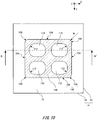
- FIG.10 is a drawing illustrating the shape of a discharge electrode 100 of an eighth embodiment. Similar to FIG. 3 , it illustrates a top view of the A-A' section of FIG. 2 .
- the electric dust collector 200 of the eighth embodiment is the same as the electric dust collector 200 of the fourth embodiment, except that the shape and number of its through-opening portion 110 and protrusion of its edge portion 112 of the through-opening portion 110 are different. Thus, repetition of explanation about the other configurations is omitted, and the same reference numerals are used to describe the same members.
- the discharge electrode 100 of the present example has four through-opening portions 110 that are arrayed in 2 rows and 2 columns on the X-Y plane.
- the number of the through-opening portions 110 is not limited to this case and may be different from that of the present example.
- the discharge electrode 100 of the present example has in its entire region a curvature radius which is equal to or longer than the gap length d that encompasses not only the edge portions 102 of the discharge electrode 100 but also the edge portion 112 of the through-opening portion 110.
- FIG.11 is a cross-sectional view of the discharge electrodes 100 of the eighth embodiment seen from a lateral direction. Specifically, FIG. 11 is a cross-sectional view illustrating the B-B' section of FIG. 10 .
- a through-opening portion 110 of the discharge electrode 100 of the present example has an edge portion 112 that protrudes toward the opposite electrode 10. The protruding length of the edge portion 112 is q.
- the edge portion 112 of a plurality of through-opening portions 110 protrude.
- at least one among the plurality of the through-opening portions 110 may have an edge portion 112 that protrudes toward the opposite electrode 10.
- it may have one through-opening portion 110, and the one through-opening portion 110 may have an edge portion 112 that protrudes toward the opposite electrode 10.
- the discharge electrode 100 may be formed by machine work such as press work to cause the edge portion 112 of the through-opening portion 110 to protrude. According to the discharge electrode 100 of the present example, it is possible for corona discharges 2 to be easily generated, as compared with a situation in which an edge portion 112 that does not protrude is used.
- FIG. 12 is a drawing illustrating the shape of a discharge electrode 100 of a ninth embodiment. Similar to FIG. 3 , it illustrates a top view of the A-A' section of FIG. 2 .
- the electric dust collector 200 of the ninth embodiment is the same as the electric dust collector 200 of the eighth embodiment, except that the protruding length of its edge portions 112 of through-opening portions 110 differ according to their positions in the X-direction, and vertex portions of the edge portions 112 of the through-opening portions 110 are not round chamfered. Note that, the vertex portions of the edge portions 112 of the through-opening portions 110 may be round chamfered. Thus, repetition of explanation about the other configurations is omitted, and the same reference numerals are used to describe the same members.
- the discharge electrode 100 of the present example has a total of nine through-opening portions 110 that are arrayed in 3 rows and 3 columns on the X-Y plane.
- the number of the through-opening portions 110 is not limited to this case and may be different from that of the present example.
- FIG. 13 is a cross-sectional view of the discharge electrode 100 of the ninth embodiment seen from a lateral direction. Specifically, FIG. 13 is a cross-sectional view illustrating the C-C' section of FIG. 12 .
- Exhaust gas introduced into an electric dust collector 200 flows in the X-direction.
- the discharge electrode 100 of the present example has a plurality of through-opening portions 100 having the edge portions 112 that protrude toward the opposite electrode 10.
- the protruding length of the edge portions 112 of the through-opening portions 110 is different between the upstream side and the downstream side of the exhaust gas. This can change likelihood of corona discharges 2 to be generated between upstream and downstream of the exhaust gas.
- the through-opening portions 110 are disposed in 3 rows along the X-direction.
- the protruding length of the edge portions 112 of the through-opening portions 110 is q1 on the upstream side, q2 on the midstream side, and q3 on the downstream side.
- q1 is the longest
- q3 is the shortest
- q2 is the length between q1 and q3. That is, the protruding length of the edge portions 112 is longer on the upstream side than on the downstream side.
- the protruding length of the edge portion 112 of the through-opening portion 110 can enhance dust collection capability on downstream side if it is longer on the downstream side than that on the upstream side. This can prevent the particles from being rapidly accumulated on the upstream side, and thus uneven accumulation of particles between the upstream side and the downstream side can be reduced. Thus, it is possible to suppress increase of a maintenance burden on removal of particles.
- FIG.14 is a perspective view illustrating a configuration of an electric dust collector 200 of a tenth embodiment.
- the electric dust collector 200 of the present example has a configuration in which a plurality of first units 210 having opposite electrodes 10 and discharge electrodes 100 is layered. In other words, the electric dust collector 200 of the present example has redundancy from top to bottom.
- One first unit 210 is configured with one opposite electrode 10 and one discharge electrode 100. In the present example, a gap length between adjacent electrodes may all be the same.
- one first unit 210 is configured with an opposite electrode 10-1 and a discharge electrode 100-1.
- one first unit 210 is configured with an opposite electrode 10-2 and a discharge electrode 100-2.
- One first unit 210 is configured with an opposite electrode 10-3 and a discharge electrode 100-3.
- three first units 210 are layered in the Z-direction. Note that, the number of layers of the first unit 210 is not limited to this case and the number of layers may be more than three.
- a single opposite electrode 10-4 is disposed opposed to the discharge electrode 100-3 that is positioned at the upper edge portion in the layered direction among the discharge electrode 100-1, discharge electrode 100-2, and discharge electrode 100-3.
- the single opposite electrode 10-4 may be omitted.
- the opposite electrode 10-1 to the opposite electrode 10-4 may be the opposite electrodes 10 described in the first to the ninth embodiments mentioned above.
- the discharge electrode 100-1 to the discharge electrode 100-3 (hereinafter, they may be referred to as a discharge electrode 100) may be the discharge electrodes 100 described in the first to the ninth embodiments mentioned above. Thus, description of the opposite electrode 10 and the discharge electrode 100 is omitted.
- each discharge electrode 100 that configures the first unit 210 does not have a protruding portion in a thorn-like shape or the like. Thus, it is possible to prevent a position at which corona discharges 2 is generated is to be fixed.
- FIG. 15 is a perspective view illustrating a configuration of an electric dust collector 200 of an eleventh embodiment.
- a configuration of the electric dust collector 200 of the present example is the same as the configuration of the electric dust collector 200 of the tenth embodiment, except that the gap length between an opposite electrode 10 and a discharge electrode 100 of the electric dust collector 200 of the present example differ according to a layered direction position of a first unit 210.
- repetition of explanation about the other configurations is omitted, and the same reference numerals are used to describe the same members.
- the layered direction of the first unit 210 is the Z-direction.
- a discharge electrode 100-3 is positioned at the upper edge portion in the Z-direction among a discharge electrode 100-1 to the discharge electrode 100-3.
- the discharge electrode 100-3 and an opposite electrode 10-3 form a pair.
- the opposite electrode 10-3 and the discharge electrode 100-3 configure the first unit 210.
- a gap length d2 between the opposite electrode 10-3 and the discharge electrode 100-3 means the gap length between the opposite electrode 10-3 and the discharge electrode 100-3 at the upper edge portion in the Z-direction.
- a gap length d1 between an opposite electrode 10-2 and a discharge electrode 100-2 means the gap length between the opposite electrode 10-3 and the discharge electrode 100-3 at the center portion in the Z-direction.
- the gap length d2 between the opposite electrode 10-3 and the discharge electrode 100-3 is greater than the gap length d1 between the opposite electrode 10-2 and the discharge electrode 100-2.
- a discharge electrode 100-1 is positioned at the lower edge portion in the Z-direction among the discharge electrode 100-1 to the discharge electrode 100-3.
- the gap length between the opposite electrode 10-1 and the discharge electrode 100-1 of the first unit located at the lower edge portion in the layered direction of the plurality of layered first units 210 may also be d2.
- the gap length d2 at the upper edge portion and the lower edge portion in the Z-direction is greater than the gap length d1 at the center portion in the Z-direction.
- the gap length of the edge portion of one of the upper edge portion and the lower edge portion in the Z-direction may be greater than that of the center portion.
- respective gap length between the discharge electrode 100 and its two adjacent opposite electrodes 10 is equal.
- the gap length between the discharge electrode 100-1 and the opposite electrode 10-1 is equal to the gap length between the discharge electrode 100-1 and the opposite electrode 10-2, and is d2.
- the gap length between the discharge electrode 100-2 and the opposite electrode 10-2 is equal to the gap length between the discharge electrode 100-2 and the opposite electrode 10-3, and is d1.
- the gap length between the discharge electrode 100-3 and the opposite electrode 10-3 is equal to the gap length between the discharge electrode 100-3 and the opposite electrode 10-4, and is d2.
- respective gap length between the discharge electrode 100 and its two adjacent opposite electrodes 10 may also be different from each other. Specifically, between the two adjacent opposite electrodes 10, the opposite electrode 10 on the side closer to the edge portion in the Z-direction may have greater gap length between itself and the discharge electrode 100, as compared with the gap length between the other opposite electrode 10 and the discharge electrode 100.
- the gap length between the discharge electrode 100-1 and the opposite electrode 10-1 may be greater than the gap length between the discharge electrode 100-1 and the opposite electrode 10-2.
- the gap length between the discharge electrode 100-3 and the opposite electrode 10-4 may be greater than the gap length between the discharge electrode 100-3 and the opposite electrode 10-3.
- the gap length between the opposite electrode 10 and the discharge electrode 100 may gradually get longer toward the upper edge portion and the lower edge portion from the center portion in the Z-direction.
- FIG. 16 is a perspective view illustrating a configuration of an electric dust collector 200 of a twelfth embodiment.
- the electric dust collector 200 of the present example has a second unit 220 provided at at least both edge portions in the Z-direction. Except this point, a configuration of the electric dust collector 200 of the present example is the same as the configuration of the electric dust collector 200 of the tenth embodiment. Thus, repetition of explanation about the other configurations is omitted, and the same reference numerals are used to describe the same members.
- first units 210 is layered at the center portion in the Z-direction.
- two first units 210 are layered.
- more than two first units 210 may be layered.
- Structure of the first unit 210 is the same as that of the tenth embodiment.
- second units 220 are provided at at least both edge portions in the Z-direction.
- the second unit 220 has an edge portion counter electrode 190-1 and a protruding type discharge electrode 180-1.
- the edge portion counter electrode 190-1 as a third electrode plate is an electrode plate having GND potential, and also referred to as a GND electrode.
- the protruding type discharge electrode 180-1 as a fourth electrode plate is an electrode plate having high potential.
- the protruding type discharge electrode 180-1 is provided opposite to the edge portion counter electrode 190-1.
- the protruding type discharge electrode 180-1 and the edge portion counter electrode 190-1 may be disposed parallel to the X-Y plane.
- An edge portion 182 of the protruding type discharge electrode 180-1 is positioned on the inner side relative to an edge portion 192 of the edge portion counter electrode 190-1.
- the edge portion 182 means an edge portion in the direction parallel to the X-Y plane.
- a negative high voltage is applied to the protruding type discharge electrode 180-1 of the present example by a DC power source 20.
- the edge portion counter electrode 190-1 is grounded.
- an edge portion 182 of the protruding type discharge electrode 180-1 has a protruding portion 184.
- a projected shape of the protruding portion 184 in the X-Y plane may be a triangle shape.
- the protruding portion 184 of the present example is in a thorn-like shape or in a saw tooth shape.
- a plurality of protruding portions 184 is provided along the edge portion 182.
- the protruding portion 184 may have protrusion length of approximately between 1 mm and 5 mm inclusive.
- a pitch is defined such that between 3 and 5 protruding portions 184 inclusive are to be provided per one centimeter.
- the protruding portion 184 may be provided along all of its sides, or the protruding portion 184 may be provide along its specific sides only.
- the second unit 220 has an edge portion counter electrode 190-2 and a protruding type discharge electrode 180-2.
- the edge portion counter electrode 190-2 is the third electrode plate
- the protruding type discharge electrode 180-2 is the fourth electrode plate.
- a configuration and an applied voltage of the second unit 220 at the upper edge portion in the Z-direction may be similar to those of the second unit 220 disposed at the lower edge portion.
- one second unit 220 is provided to both edge portions in the Z-direction.
- a plurality of second units 220 may be provided to the upper edge portion and the lower edge portion in the Z-direction respectively.
- the first unit 210 is layered at the middle portion in the layered direction. It is desirable for the number of layers of the second units 220 not to exceed the number of layers of the first unit 210.
- FIG. 17 is a drawing illustrating a configuration of an electric dust collector 200 of a thirteenth embodiment.
- An electric dust collector 200 of the thirteenth embodiment is the same as the electric dust collectors 200 of the first to the twelfth embodiments, except that a positive high voltage is applied to the discharge electrode 100 by a DC power source 20.
- the opposite electrode 10 or the edge portion counter electrode 190
- a negative high voltage is applied to the discharge electrode 100.
- a positive high voltage is applied instead of a negative high voltage in the first to the twelfth embodiments.
- FIG. 18 is a schematic diagram illustrating an overview of an exhaust gas cleaning system 400.
- An exhaust gas cleaning system 400 removes harmful substances such as sulfur constituents included in exhaust gas exhausted from an engine of a vehicle.
- the exhaust gas cleaning system 400 has an electric dust collector 200, a scrubber 300, and a pumping-up pump 350.
- the electric dust collector 200 is provided upstream from the scrubber 300.
- Exhaust gas is introduced from the electric dust collector 200 into the scrubber 300 through an exhaust gas inlet tube 306.
- the electric dust collector 200 used herein is the electric dust collector 200 of the first to the thirteenth embodiments mentioned above.
- the scrubber 300 has a reaction tower 302, a nozzle 304, and the exhaust gas inlet tube 306.
- the reaction tower 302 has interior space extending out into its height direction.
- the height direction refers to the direction extending out from a bottom portion side 308 where exhaust gas is introduced into the reaction tower 302 into a top portion 310 where the exhaust gas is exhausted therefrom.
- the exhaust gas inlet tube 306 is positioned near the bottom portion side 308 of the reaction tower 302.
- the exhaust gas inlet tube 306 is provided such that the exhaust gas introduced from the exhaust gas inlet tube 306 spirally circulates along inner side side-surface of the reaction tower 302.
- a radius of the reaction tower 302 may be between 0.3m and 10m inclusive.
- a washing water pipe 312 through which washing water flows is disposed at an interior portion of the scrubber 300.
- the washing water pipe 312 is disposed near the top portion 310 of the reaction tower 302.
- the washing water pipe 312 of the present example transports washing water in a direction perpendicular to the height direction of the reaction tower 302.
- the washing water pipe 312 is supplied with washing water from the pumping-up pump 350.
- the washing water pipe 312 is provided with the nozzle 304.
- the nozzle 304 processes exhaust gas by jetting out washing water 314 from the top portion 310 to the bottom portion side 308 relative to the exhaust gas.
- the washing water 314 jetted out from the nozzle 304 contacts exhaust gas passing through the interior portion within the reaction tower 302 and absorbs sulfur constituents and the like included in the exhaust gas. Fluid that absorbs sulfur constituent and the like is accumulated on the bottom portion side 308 of the reaction tower 302 and exhausted to the external portion of the reaction tower 302 as drainage.
- the exhaust gas cleaning system 400 of the present example harmful substances which the electric dust collector 200 alone cannot remove completely, can be removed. Because the electric dust collector 200 of the first to the thirteenth embodiments is used for the exhaust gas cleaning system 400, it is possible to restrain corrosion of opposite electrode 10 that results from a position at which a corona discharge 2 is generated is being fixed. Also, the embodiments mentioned above are applied to a two-stage type electric dust collector of which charging portion and dust collecting portion are separately configured.
Landscapes
- Electrostatic Separation (AREA)
- Treating Waste Gases (AREA)
Abstract
Description
- The present invention relates to an electric dust collector and an exhaust gas cleaning system.
- An electric dust collector is used for collecting particles in exhaust gas in different regions inside all sorts of plants, tunnels, etc. Conventionally, in an electric dust collector of which tabular discharge electrode and tabular opposite electrode are opposing each other, a discharge electrode has a thorn-like shaped protruding portion at its edge portion just like saw teeth (for example, see Patent Document 1). The discharge electrode generates corona discharges between the thorn-like shaped protruding portions and the opposite electrode, and charges particles by the corona discharge. A dust collecting electrode is to collect the charged particles by Coulomb's force (for example, see Patent Document 1).
- Patent Document 1: Japanese Patent No.
2971461 - Corona discharges are generated between a thorn-like shaped protruding portion of a discharge electrode and an opposite electrode. Therefore, if an electric dust collector is operated over a long period of time, corrosion of the opposite electrode may progress at a particular spot of the opposite electrode whereto the thorn-like shaped protruding portion correspond.
- (General Disclosure of the Invention) An Electric dust collector may include a first electrode plate and a second electrode plate. The second electrode plate may be provided opposite to the first electrode plate. An edge portion of the second electrode plate may be positioned on the inner side relative to an edge portion of the first electrode plate. The edge portion of the second electrode plate may not have a protruding portion.
- The second electrode plate may be in a flat plate shape. The second electrode plate may have a curvature radius which is equal to or longer than a gap between the first electrode plate and the second electrode plate in its entire region.
- The second electrode plate may be in a flat plate shape including a straight line portion, and a corner portion having a curvature radius.
- The second electrode plate may be in a disk shape.
- The second electrode plate may have one or more through-opening portions.
- The one or more through-opening portions may include a plurality of separate through-opening portions.
- The one or more through-opening portions may have a middle opening portion and a peripheral opening portion. The middle opening portion may be the largest opening portion. The peripheral opening portion may have an opening area smaller than that of the middle opening portion. The peripheral opening portion may be disposed around the middle opening portion.
- The second electrode plate may have one or more through-opening portions. At least one among the one or more through-opening portions may have an edge portion that protrudes toward the first electrode plate.
- It may have a plurality of through-opening portions having an edge portion that protrudes toward the first electrode plate. The protruding length of the edge portion may be different between an upstream side and a downstream side of gas introduced into the electric dust collector.
- The protruding length of the edge portions may be longer on the upstream side than that on the downstream side.
- A plurality of first units having the first electrode plates and the second electrode plates may be layered.
- Gap length between the first electrode plate and the second electrode plate of the first unit located at an edge portion in a layered direction of the plurality of layered first units may be greater than gap length between the first electrode plate and the second electrode plate of the first unit located at a center portion in the layered direction of the plurality of layered first units.
- The electric dust collector may further include a second unit. The second unit may have a third electrode plate and a fourth electrode plate. The fourth electrode plate may be provided opposite to the third electrode plate. An edge portion of the fourth electrode plate may be positioned on the inner side relative to an edge portion of the third electrode plate. An edge portion of the fourth electrode plate may have a protruding portion. The second unit may be provided at at least both edge portions in a layered direction of a plurality of layered first units.
- An exhaust gas cleaning system may include a scrubber and the above-mentioned electric dust collector. The scrubber may clean exhaust gas. The electric dust collector may be provided upstream from the scrubber.
- Note that, the summary clause mentioned above shall not necessarily describe all necessary features of embodiments of the present invention. The present invention may also be a sub-combination of the features described above.
-
FIG.1 is a perspective view illustrating a configuration of anelectric dust collector 200 of a first embodiment. -
FIG.2 is a cross-sectional view illustrating the configuration of theelectric dust collector 200 of the first embodiment. -
FIG.3 is a top view of the A-A' section ofFIG.2 . -
FIG.4 is a drawing illustrating the shape of adischarge electrode 100 of a second embodiment. -
FIG.5 is a drawing illustrating the shape of adischarge electrode 100 of a third embodiment. -
FIG. 6 is a drawing illustrating the shape of adischarge electrode 100 of a fourth embodiment. -
FIG.7 is a drawing illustrating the shape of adischarge electrode 100 of a fifth embodiment. -
FIG.8 is a drawing illustrating the shape of adischarge electrode 100 of a sixth embodiment. -
FIG.9 is a drawing illustrating the shape of adischarge electrode 100 of a seventh embodiment. -
FIG.10 is a drawing illustrating the shape of adischarge electrode 100 of an eighth embodiment. -
FIG.11 is a cross-sectional view of thedischarge electrodes 100 of the eighth embodiment seen from a lateral direction. -
FIG.12 is a drawing illustrating the shape of adischarge electrode 100 of a ninth embodiment. -
FIG. 13 is a cross-sectional view of thedischarge electrodes 100 of the ninth embodiment seen from a lateral direction. -
FIG.14 is a perspective view illustrating a configuration of anelectric dust collector 200 of a tenth embodiment. -
FIG.15 is a perspective view illustrating a configuration of anelectric dust collector 200 of an eleventh embodiment. -
FIG.16 is a perspective view illustrating a configuration of anelectric dust collector 200 of a twelfth embodiment. -
FIG. 17 is a perspective view illustrating a configuration of theelectric dust collector 200 of a thirteenth embodiment. -
FIG.18 is a schematic diagram illustrating an overview of an exhaust gas cleaning system 400. - Hereinafter, the present invention is described through the embodiments of the invention. However, the following embodiments shall not limit the claimed invention that follows. In addition, not all the combinations of features described in the embodiments are necessarily essential to means provided by aspects of the invention.
- In the present specification, technical matters are described using orthogonal coordinate axes of X-axis, Y-axis and Z-axis. The orthogonal coordinate axes are only to specify relative positions of components, and shall not limit them to specific directions. For example, the Z-axis shall not exclusively indicate a height direction relative to the ground. Note that, a positive Z-axis direction and a negative Z-axis direction are directions opposite to each other. If the Z-axis direction is referred to without specifying whether it is positive or negative, it means a direction parallel to the positive Z-axis and the negative Z-axis. Also, in the present specification, "a straight line" is to have an infinite curvature radius.
-
FIG. 1 is a perspective view illustrating a configuration of anelectric dust collector 200 of a first embodiment. Theelectric dust collector 200 collects particles in exhaust gas. The particles are soot, dust, or the like. Theelectric dust collector 200 has an opposite electrode 10-1 and adischarge electrode 100. The opposite electrode 10-1 as a first electrode plate is an electrode plate at GND potential, and also referred to as a GND electrode. Thedischarge electrode 100 as a second electrode plate is an electrode plate at high potential. Thedischarge electrode 100 is provided opposite to the opposite electrode 10-1. - In addition to the opposite electrode 10-1 and the
discharge electrode 100, theelectric dust collector 200 of the present example has an opposite electrode 10-2. The opposite electrode 10-1 and the opposite electrode 10-2 are disposed such that thedischarge electrode 100 is sandwiched therebetween. This allowscorona discharges 2 to be caused atedge portions 102 on both sides of onedischarge electrode 100. Note that, unlike the present example, theelectric dust collector 200 may be configured only with the opposite electrode 10-1 and thedischarge electrode 100. - The opposite electrode 10-1, the
discharge electrode 100, and the opposite electrode 10-2 may be layered in the Z-direction such that a gap length between thedischarge electrode 100 and the opposite electrode 10-1 in the Z-direction and a gap length between thedischarge electrode 100 and the opposite electrode 10-2 in the Z-direction become equal. The opposite electrode 10-1, the opposite electrode 10-2, and thedischarge electrode 100 may be disposed parallel to the X-Y plane. - The opposite electrode 10-1 and the opposite electrode 10-2 (hereinafter, they may be referred to as an opposite electrode 10) and the
discharge electrode 100 are in a flat plate shape. The thickness of theopposite electrode 10 and thedischarge electrode 100 may be between 1 mm and 2 mm inclusive. The plate area of theopposite electrode 10 and thedischarge electrode 100 may be between 0.3 m2 and 3 m2 inclusive. For example, theopposite electrode 10 and thedischarge electrode 100 are flat plates with the size of approximately 1m × 1m. Note that, the area of thedischarge electrode 100 is smaller than the area of theopposite electrode 10. Material for theopposite electrode 10 and thedischarge electrode 100 may be stainless steel material such as SUS304 of JIS standard. - The
opposite electrode 10 of the present example is a rectangle. Theopposite electrode 10 of the present example has anedge portion 12. Theedge portion 12 includes foursides 14 of the rectangle. The "edge portion" means an edge portion in the direction parallel to the X-Y plane. Note that, unlike the present example, theopposite electrode 10 may be in any shape such as a polygon, a circle, an oval, or the like. Thedischarge electrode 100 of the present example is in a shape that can be approximated by a rectangle. Thedischarge electrode 100 hasedge portions 102. Theedge portions 102 of thedischarge electrode 100 are positioned on the inner side relative to theedge portion 12 of theopposite electrode 10. As shown inFIG. 1 , theedge portions 102 of thedischarge electrode 100 do not include a protruding portion in a thorn-like shape or the like. - A negative high voltage is applied to the
discharge electrode 100 of the present example by aDC power source 20. Theopposite electrode 10 is grounded. This forms a high electric field region between thedischarge electrode 100 and theopposite electrode 10. - Unlike the present example, if the
discharge electrode 100 includes protruding portions in a thorn-like shape or the like, positions at which corona discharges 2 are generated are prone to be fixed to a position directly under or directly above the protruding portions. If theelectric dust collector 200 is operated over a long period of time, particles such as dust are prone to be locally accumulated on theopposite electrode 10 at positions directly under or directly above the protruding portions of thedischarge electrode 100. Accumulation of particles shortens the gap length between thedischarge electrode 100 and theopposite electrode 10. As a result, portions where the gap length is shortened will have a higher electric field than that at other portions, and an electric field necessary for transition to a spark (a spark discharge) is prone to be exceeded thereat. If a spark is generated, theopposite electrode 10 may prone to corrade. - Also, when charged particles are attracted to the
opposite electrode 10 having different potential and are accumulated thereon, a back-discharge is caused. If a position at which acorona discharge 2 is generated is fixed and charged particles are locally accumulated at a certain position, a back-discharge is generated at that certain position. If the back-discharge is steadily generated at the certain position, theopposite electrode 10 may be partially damaged. To restrain such state, it is necessary to regularly wash thedischarge electrode 100 and theopposite electrode 10 to remove particles, which increases a burden on maintenance. - On the other hand, according to the present example, because the
discharge electrode 100 does not have protruding portions, positions at which corona discharges 2 are generated are not to be fixed to particular spots. Thus,corona discharges 2 can be caused throughout linear areas which correspond to the sides of theedge portions 102 of thedischarge electrode 100. Even if corona discharges 2 are formed at spots, the spots ofcorona discharges 2 are not fixed to one location, but can move on the linear area. Thereby, corrosion of theopposite electrode 10 can be prevented from progressing locally. Also, even if theelectric dust collector 200 is operated over a long period of time, particles such as dust can be restrained from locally accumulated on thedischarge electrode 100 and theopposite electrode 10. As a result, because the gap length between thedischarge electrode 100 and theopposite electrode 10 can be prevented from changing due to the accumulation of particles, it is possible to restrain generation of spark. In addition, because particles are no longer to be locally accumulated, it is possible to reduce influence of the back-discharge. -
FIG.2 is a cross-sectional view illustrating a configuration of theelectric dust collector 200 of the first embodiment. Acorona discharge 2 negatively charges particles in exhaust gas between thedischarge electrode 100 and theopposite electrode 10. The negatively charged particles are collected at theopposite electrode 10 by Coulomb's force. -
FIG.3 illustrates a top view of the A-A' section ofFIG.2 . Thedischarge electrode 100 includesstraight line portions 104 andcorner portions 106 asedge portions 102. A phrase "If theedge portion 102 of thedischarge electrode 100 does not have a protruding portion" covers a situation where the shape of theedge portion 102 of thedischarge electrode 100 can be approximated by a polygon such as a quadrangle, a pentagon, or a hexagon. Theedge portions 102 of thedischarge electrode 100 may be in a shape made by connecting astraight line portion 104 that corresponds to a side of a polygon and acorner portion 106 of which vertex portion is rounded into a curve. Thecorner portions 106 have a curvature radius which is equal to or longer than a gap length d between theopposite electrode 10 and thedischarge electrode 100. Thedischarge electrode 100 of the present example has in its entire region a curvature radius which is equal to or longer than the gap length d. - All of the
corner portions 106 of thedischarge electrode 100 may be in a shape that is approximated by a circular-arc Rogowski electrode shape. This can make electric field concentration atcorner portions 106 relaxed. The Rogowski electrode is an electrode that forms a quasi-uniform electric field of which electric field magnitude is approximately uniform between thecorner portions 106 and thestraight line portions 104. According to thedischarge electrode 100 of the present example, a quasi-uniform electric field can be formed by relaxing edge portion effect (edge effect) of a parallel plate electrode, and thus it is possible to preventcorona discharges 2 from being concentrated at one location of thecorner portions 106 of thedischarge electrode 100. -
FIG.4 is a drawing illustrating the shape of adischarge electrode 100 of a second embodiment. Similar toFIG. 3 , it illustrates a top view of the A-A' section ofFIG. 2 . Anelectric dust collector 200 of the second embodiment is the same as theelectric dust collector 200 of the first embodiment, except for the shape of thedischarge electrode 100. Thus, repetition of explanation about the other configurations is omitted, and the same reference numerals are used to describe the same members. Thedischarge electrode 100 of the present example is a rectangle.Corner portions 106 are not round chamfered. Thus, a process of manufacturing thedischarge electrode 100 can be simplified. - In the present example also,
edge portions 102 of thedischarge electrode 100 do not have protruding portions. In the present example, it is not essential for theedge portions 102 of thedischarge electrode 100 to have a curvature radius which is equal to or longer than the gap length d in its entire region. According to thedischarge electrode 100 of the present example also, a phenomenon in which a position at which acorona discharge 2 is generated to be fixed can be reduced in comparison with a situation where thedischarge electrode 100 has a protruding portion in a thorn-like shape or the like. Note that, unlike the present example, the shape of thedischarge electrode 100 may be a convex polygon such as a pentagon, a hexagon, or the like which are not round chamfered. -
FIG. 5 is a drawing illustrating the shape of adischarge electrode 100 of a third embodiment. Similar toFIG. 3 , it illustrates a top view of the A-A' section ofFIG. 2 . Anelectric dust collector 200 of the third embodiment is the same as theelectric dust collectors 200 of the first and second embodiments, except for the shape of thedischarge electrode 100. Thus, repetition of explanation about the other configurations is omitted, and the same reference numerals are used to describe the same members. - The
discharge electrode 100 of the present example is in a disk shape. That is, anedge portion 102 of thedischarge electrode 100 is a circle. A phrase "If theedge portion 102 of thedischarge electrode 100 does not have a protruding portion" covers a situation where theedge portion 102 of thedischarge electrode 100 is formed by a closed curve such as a circle or an oval. In the present example, the radius of thedischarge electrode 100 is greater than the gap length d between theopposite electrode 10 and thedischarge electrode 100 in the Z-direction. Thus, thedischarge electrode 100 has a curvature radius which is equal to or longer than the gap length d in its entire region. - According to the present example, the
edge portion 102 of thedischarge electrode 100 is formed by a curve with a uniform curvature radius. Thus, the electric field to be caused is substantially the same regardless of its position at theedge portion 102. Thus,corona discharge 2 can be caused evenly throughout theedge portions 102 of thedischarge electrode 100 without being influenced by thecorner portions 106. Even if corona discharges 2 are formed at spots, the spots forcorona discharges 2 are not fixed to one location, but can move along the circular shapededge portion 102 randomly. Thus, generation of spark can be restrained, and corrosion of thedischarge electrode 100 can be delayed. -
FIG.6 is a drawing illustrating the shape of adischarge electrode 100 of a fourth embodiment. Similar toFIG. 3 , it illustrates a top view of the A-A' section ofFIG. 2 . Anelectric dust collector 200 of the fourth embodiment is the same as theelectric dust collector 200 of the first embodiment, except that itsdischarge electrode 100 has a through-openingportion 110. Thus, repetition of explanation about the other configurations is omitted, and the same reference numerals are used to describe the same members. -
Edge portions 112 of the through-openingportion 110 may be in a shape of a polygon of which vertex portions are round chamfered. Anedge portion 112 includeslinear edge portion 114 that corresponds to four sides of a rectangle shape and acorner edge portion 116 of which vertex portion is rounded into a curve.Corner edge portions 116 have a curvature radius which is equal to or longer than the gap length d between theopposite electrode 10 and thedischarge electrode 100. Thus, thedischarge electrode 100 of the present example has in its entire region a curvature radius which is equal to or longer than the gap length d that encompasses not only theedge portions 102 but also the middle region including theedge portion 112 of the through-openingportion 110. - In the present example, if a high electric field region is formed between the
discharge electrode 100 and theopposite electrode 10,corona discharges 2 can be generated not only at theedge portions 102 of thedischarge electrode 100 but also at theedge portion 112 of the through-openingportion 110. Thus, by using thedischarge electrode 100 having the through-openingportion 110, the number of locations for acorona discharge 2 to be generated can be increased as compared with a situation in which adischarge electrode 100 that does not have a through-openingportion 110 is used. Therefore, in the present example, it is possible to improve dust collection quantity per area of electric dust collector 200 (dust collection efficiency), as compared with that of the first to the third embodiments. - In
FIG. 6 , a situation where both theedge portions 102 of thedischarge electrode 100 and theedge portions 112 of the through-openingportion 110 are in a shape of a polygon of which vertex portions are round chamfered is illustrated. However, thedischarge electrode 100 of the present example is not limited to this situation and thus it may have a through-openingportion 110 having a different shape from the shape of theedge portions 102 of thedischarge electrode 100. -
FIG.7 is a drawing illustrating the shape of adischarge electrode 100 of a fifth embodiment. Similar toFIG. 3 , it illustrates a top view of the A-A' section ofFIG. 2 . Anelectric dust collector 200 of the fifth embodiment is the same as theelectric dust collector 200 of the third embodiment, except that itsdischarge electrode 100 has a through-openingportion 110. Thus, repetition of explanation about the other configurations is omitted, and the same reference numerals are used to describe the same members. - In the present example, the
edge portion 112 of the through-openingportion 110 is a circle. Unlike the present example, theedge portion 112 of the through-openingportion 110 may be in an oval shape or in another shape. In the present example, by using thedischarge electrode 100 having the through-openingportion 110, it is possible to increase the number of locations for acorona discharge 2 to be generated as compared with a situation in which adischarge electrode 100 that does not have a through-openingportion 110 is used. -
FIG. 8 is a drawing illustrating the shape of adischarge electrode 100 of a sixth embodiment. Similar toFIG. 3 , it illustrates a top view of the A-A' section ofFIG. 2 . Anelectric dust collector 200 of the sixth embodiment is the same as theelectric dust collector 200 of the fifth embodiment, except that the shape of thedischarge electrode 100 and the shape of its through-openingportion 110 are different. Thus, repetition of explanation about the other configurations is omitted, and the same reference numerals are used to describe the same members. - The
discharge electrode 100 of the present example has a plurality of annular portions that is concentrically disposed. Specifically, thedischarge electrode 100 has a firstannular portion 101, and a secondannular portion 103 that is disposed on the inner side of the firstannular portion 101. Afirst opening portion 111 which is a annular shaped through-opening, is provided between the firstannular portion 101 and the secondannular portion 103. Asecond opening portion 113 which is a circular shaped through-opening, is provided on the inner side of the secondannular portion 103. In other words, thedischarge electrode 100 of the present example has thefirst opening portion 111 and thesecond opening portion 113 as a plurality of separate through-openingportions 110. - The
edge portion 102 of the firstannular portion 101 of the present example corresponds to the outer circumference of the firstannular portion 101 and constitutes theedge portion 102 of thedischarge electrode 100. The outer circumference of the firstannular portion 101 has a radius which is equal to or longer than the gap length d.First edge portion 115 which is an edge portion of thefirst opening portion 111, corresponds to the inner circumference of the firstannular portion 101 and the outer circumference of the secondannular portion 103. The inner circumference of the firstannular portion 101 and the outer circumference of the secondannular portion 103 have a radius which is equal to or longer than the gap length d. Thesecond edge portion 117 which is an edge portion of thesecond opening portion 113, corresponds to the inner circumference of the secondannular portion 103. The inner circumference of the secondannular portion 103 also has a radius which is equal to or longer than the gap length d. Thus, thedischarge electrode 100 of the present example also has in its entire region a curvature radius which is equal to or longer than the gap length d that encompasses not only theedge portion 102 but also its central region. - The
discharge electrode 100 of the present example includes a plurality of separate through-openingportions 110. This makes it possible to increase the number of locations for acorona discharge 2 to be generated as compared with a situation in which there is one through-openingportion 110. -
FIG. 9 is a drawing illustrating the shape of adischarge electrode 100 of a seventh embodiment. Similar toFIG. 3 , it illustrates a top view of the A-A' section ofFIG. 2 . Theelectric dust collector 200 of the seventh embodiment is the same as theelectric dust collector 200 of the fourth embodiment, except that the shape of thedischarge electrode 100 and the shape and number of its through-openingportion 110 are different. Thus, repetition of explanation about the other configurations is omitted, and the same reference numerals are used to describe the same members. - The
discharge electrode 100 of the present example has a plurality of separate through-openingportions 110. The through-openingportions 110 may include amiddle opening portion 140 and a plurality of peripheral openingportions 146. In the present example, it includes onemiddle opening portion 140 and four peripheral openingportions 146. Themiddle opening portion 140 has the largest opening area among the plurality of through-openingportions 110. Respective peripheral openingportions 146 have respective opening areas smaller than that of themiddle opening portion 140. Respective peripheral openingportions 146 are disposed around themiddle opening portion 140. - In the present example, a
middle edge portion 122 which is the edge portion of themiddle opening portion 140, is in a circle shape. Aperipheral edge portion 123 which is the edge portion of theperipheral opening portion 146, is in a polygon shape of which vertex portions are rounded. However, the shapes of themiddle edge portion 122 and theperipheral edge portion 123 are not limited to this case. Thedischarge electrode 100 has in its entire region a curvature radius which is equal to or longer than the gap length d that encompasses not only theedge portions 102 but also themiddle edge portion 122 and theperipheral edge portion 123. - Generally, electric fields are concentrated at the
edge portions 102 of thedischarge electrode 100. Electric fields are not likely to be concentrated at the middle portion on the inner side of thedischarge electrode 100. Thus, the middle portion on the inner side of thedischarge electrode 100 has a wide region where a high electric field is not formed. However, according to thedischarge electrode 100 of the present example, themiddle opening portion 140 on the inner side of thedischarge electrode 100 is larger than the peripheral openingportions 146. This causes electric field strength to become high at themiddle edge portion 122 that is the edge portion of themiddle opening portion 140, and thus it is possible forcorona discharges 2 to be also generated at the middle portion of thedischarge electrode 100. -
FIG.10 is a drawing illustrating the shape of adischarge electrode 100 of an eighth embodiment. Similar toFIG. 3 , it illustrates a top view of the A-A' section ofFIG. 2 . Theelectric dust collector 200 of the eighth embodiment is the same as theelectric dust collector 200 of the fourth embodiment, except that the shape and number of its through-openingportion 110 and protrusion of itsedge portion 112 of the through-openingportion 110 are different. Thus, repetition of explanation about the other configurations is omitted, and the same reference numerals are used to describe the same members. - The
discharge electrode 100 of the present example has four through-openingportions 110 that are arrayed in 2 rows and 2 columns on the X-Y plane. However, the number of the through-openingportions 110 is not limited to this case and may be different from that of the present example. Thedischarge electrode 100 of the present example has in its entire region a curvature radius which is equal to or longer than the gap length d that encompasses not only theedge portions 102 of thedischarge electrode 100 but also theedge portion 112 of the through-openingportion 110. -
FIG.11 is a cross-sectional view of thedischarge electrodes 100 of the eighth embodiment seen from a lateral direction. Specifically,FIG. 11 is a cross-sectional view illustrating the B-B' section ofFIG. 10 . A through-openingportion 110 of thedischarge electrode 100 of the present example has anedge portion 112 that protrudes toward theopposite electrode 10. The protruding length of theedge portion 112 is q. - In the present example, the
edge portion 112 of a plurality of through-openingportions 110 protrude. However, unlike the present example, at least one among the plurality of the through-openingportions 110 may have anedge portion 112 that protrudes toward theopposite electrode 10. Also, it may have one through-openingportion 110, and the one through-openingportion 110 may have anedge portion 112 that protrudes toward theopposite electrode 10. Thedischarge electrode 100 may be formed by machine work such as press work to cause theedge portion 112 of the through-openingportion 110 to protrude. According to thedischarge electrode 100 of the present example, it is possible forcorona discharges 2 to be easily generated, as compared with a situation in which anedge portion 112 that does not protrude is used. -
FIG. 12 is a drawing illustrating the shape of adischarge electrode 100 of a ninth embodiment. Similar toFIG. 3 , it illustrates a top view of the A-A' section ofFIG. 2 . Theelectric dust collector 200 of the ninth embodiment is the same as theelectric dust collector 200 of the eighth embodiment, except that the protruding length of itsedge portions 112 of through-openingportions 110 differ according to their positions in the X-direction, and vertex portions of theedge portions 112 of the through-openingportions 110 are not round chamfered. Note that, the vertex portions of theedge portions 112 of the through-openingportions 110 may be round chamfered. Thus, repetition of explanation about the other configurations is omitted, and the same reference numerals are used to describe the same members. Thedischarge electrode 100 of the present example has a total of nine through-openingportions 110 that are arrayed in 3 rows and 3 columns on the X-Y plane. However, the number of the through-openingportions 110 is not limited to this case and may be different from that of the present example. -
FIG. 13 is a cross-sectional view of thedischarge electrode 100 of the ninth embodiment seen from a lateral direction. Specifically,FIG. 13 is a cross-sectional view illustrating the C-C' section ofFIG. 12 . Exhaust gas introduced into anelectric dust collector 200 flows in the X-direction. Thedischarge electrode 100 of the present example has a plurality of through-openingportions 100 having theedge portions 112 that protrude toward theopposite electrode 10. In thedischarge electrode 100 of the present example, the protruding length of theedge portions 112 of the through-openingportions 110 is different between the upstream side and the downstream side of the exhaust gas. This can change likelihood ofcorona discharges 2 to be generated between upstream and downstream of the exhaust gas. - In the present example, the through-opening
portions 110 are disposed in 3 rows along the X-direction. The protruding length of theedge portions 112 of the through-openingportions 110 is q1 on the upstream side, q2 on the midstream side, and q3 on the downstream side. As shown inFIG. 13 , q1 is the longest, q3 is the shortest, and q2 is the length between q1 and q3. That is, the protruding length of theedge portions 112 is longer on the upstream side than on the downstream side. - By making the protruding length of the
edge portion 112 longer on the upstream side than on the downstream side, it is possible to makecorona discharges 2 more likely to be generated on the upstream side than on the downstream side. This can make dust collection easier in an upstream side region than in a downstream side region. Concentration of particles included in exhaust gas is the highest in the upstream side region, and gets lower as the exhaust gas progresses to the downstream side region. Thus, according to the present example, dust can be collected efficiently on the upstream side where the concentration of particles is higher than that of the downstream side. - However, unlike the present example, the protruding length of the
edge portion 112 of the through-openingportion 110 can enhance dust collection capability on downstream side if it is longer on the downstream side than that on the upstream side. This can prevent the particles from being rapidly accumulated on the upstream side, and thus uneven accumulation of particles between the upstream side and the downstream side can be reduced. Thus, it is possible to suppress increase of a maintenance burden on removal of particles. -
FIG.14 is a perspective view illustrating a configuration of anelectric dust collector 200 of a tenth embodiment. Theelectric dust collector 200 of the present example has a configuration in which a plurality offirst units 210 havingopposite electrodes 10 and dischargeelectrodes 100 is layered. In other words, theelectric dust collector 200 of the present example has redundancy from top to bottom. Onefirst unit 210 is configured with oneopposite electrode 10 and onedischarge electrode 100. In the present example, a gap length between adjacent electrodes may all be the same. - In the present example, one
first unit 210 is configured with an opposite electrode 10-1 and a discharge electrode 100-1. Similarly, onefirst unit 210 is configured with an opposite electrode 10-2 and a discharge electrode 100-2. Onefirst unit 210 is configured with an opposite electrode 10-3 and a discharge electrode 100-3. In the present example, threefirst units 210 are layered in the Z-direction. Note that, the number of layers of thefirst unit 210 is not limited to this case and the number of layers may be more than three. - In the present example, a single opposite electrode 10-4 is disposed opposed to the discharge electrode 100-3 that is positioned at the upper edge portion in the layered direction among the discharge electrode 100-1, discharge electrode 100-2, and discharge electrode 100-3. The single opposite electrode 10-4 may be omitted.
- The opposite electrode 10-1 to the opposite electrode 10-4 (may be referred to as an opposite electrode 10) may be the
opposite electrodes 10 described in the first to the ninth embodiments mentioned above. The discharge electrode 100-1 to the discharge electrode 100-3 (hereinafter, they may be referred to as a discharge electrode 100) may be thedischarge electrodes 100 described in the first to the ninth embodiments mentioned above. Thus, description of theopposite electrode 10 and thedischarge electrode 100 is omitted. - According to the present example, because the plurality of
first units 210 is layered, dust collection efficiency can be improved as compared with a situation in which there is one unit. Even if the plurality of first units is layered, eachdischarge electrode 100 that configures thefirst unit 210 does not have a protruding portion in a thorn-like shape or the like. Thus, it is possible to prevent a position at which corona discharges 2 is generated is to be fixed. -
FIG. 15 is a perspective view illustrating a configuration of anelectric dust collector 200 of an eleventh embodiment. A configuration of theelectric dust collector 200 of the present example is the same as the configuration of theelectric dust collector 200 of the tenth embodiment, except that the gap length between anopposite electrode 10 and adischarge electrode 100 of theelectric dust collector 200 of the present example differ according to a layered direction position of afirst unit 210. Thus, repetition of explanation about the other configurations is omitted, and the same reference numerals are used to describe the same members. - In the present example, the layered direction of the
first unit 210 is the Z-direction. A discharge electrode 100-3 is positioned at the upper edge portion in the Z-direction among a discharge electrode 100-1 to the discharge electrode 100-3. The discharge electrode 100-3 and an opposite electrode 10-3 form a pair. The opposite electrode 10-3 and the discharge electrode 100-3 configure thefirst unit 210. In the present example, a gap length d2 between the opposite electrode 10-3 and the discharge electrode 100-3 means the gap length between the opposite electrode 10-3 and the discharge electrode 100-3 at the upper edge portion in the Z-direction. - On the other hand, a gap length d1 between an opposite electrode 10-2 and a discharge electrode 100-2 means the gap length between the opposite electrode 10-3 and the discharge electrode 100-3 at the center portion in the Z-direction. In the present example, the gap length d2 between the opposite electrode 10-3 and the discharge electrode 100-3 is greater than the gap length d1 between the opposite electrode 10-2 and the discharge electrode 100-2.
- In the present example, a discharge electrode 100-1 is positioned at the lower edge portion in the Z-direction among the discharge electrode 100-1 to the discharge electrode 100-3. The gap length between the opposite electrode 10-1 and the discharge electrode 100-1 of the first unit located at the lower edge portion in the layered direction of the plurality of layered
first units 210 may also be d2. Thus, in the present example, the gap length d2 at the upper edge portion and the lower edge portion in the Z-direction is greater than the gap length d1 at the center portion in the Z-direction. However, unlike the present example, the gap length of the edge portion of one of the upper edge portion and the lower edge portion in the Z-direction may be greater than that of the center portion. - In the present example, respective gap length between the
discharge electrode 100 and its two adjacentopposite electrodes 10 is equal. Specifically, the gap length between the discharge electrode 100-1 and the opposite electrode 10-1 is equal to the gap length between the discharge electrode 100-1 and the opposite electrode 10-2, and is d2. The gap length between the discharge electrode 100-2 and the opposite electrode 10-2 is equal to the gap length between the discharge electrode 100-2 and the opposite electrode 10-3, and is d1. The gap length between the discharge electrode 100-3 and the opposite electrode 10-3 is equal to the gap length between the discharge electrode 100-3 and the opposite electrode 10-4, and is d2. - However, unlike the present example, respective gap length between the
discharge electrode 100 and its two adjacentopposite electrodes 10 may also be different from each other. Specifically, between the two adjacentopposite electrodes 10, theopposite electrode 10 on the side closer to the edge portion in the Z-direction may have greater gap length between itself and thedischarge electrode 100, as compared with the gap length between the otheropposite electrode 10 and thedischarge electrode 100. - From the viewpoint of making the gap length greater on the side closer to the lower edge portion in the Z-direction than the gap length at the center portion, the gap length between the discharge electrode 100-1 and the opposite electrode 10-1 may be greater than the gap length between the discharge electrode 100-1 and the opposite electrode 10-2. From the viewpoint of making the gap length greater on the side closer to the upper edge portion in the Z-direction than the gap length at the center portion, the gap length between the discharge electrode 100-3 and the opposite electrode 10-4 may be greater than the gap length between the discharge electrode 100-3 and the opposite electrode 10-3.
- In the present example, a situation where three
first units 210 are layered is described. However, unlike the present example, more than threefirst units 210 may also be layered. In this case, the gap length between theopposite electrode 10 and thedischarge electrode 100 may gradually get longer toward the upper edge portion and the lower edge portion from the center portion in the Z-direction. - If a plurality of
first units 210 is layered to configure layered structure, exhaust gas does not flow easily at an edge portion of thefirst unit 210 in the layered direction. However, in theelectric dust collector 200 of the present example, by making the gap length wider at an edge portion of thefirst unit 210 in the layered direction, dust can be collected easier. -
FIG. 16 is a perspective view illustrating a configuration of anelectric dust collector 200 of a twelfth embodiment. Theelectric dust collector 200 of the present example has asecond unit 220 provided at at least both edge portions in the Z-direction. Except this point, a configuration of theelectric dust collector 200 of the present example is the same as the configuration of theelectric dust collector 200 of the tenth embodiment. Thus, repetition of explanation about the other configurations is omitted, and the same reference numerals are used to describe the same members. - In the present example, a plurality of
first units 210 is layered at the center portion in the Z-direction. In the present example, twofirst units 210 are layered. However, unlike the present example, more than twofirst units 210 may be layered. Structure of thefirst unit 210 is the same as that of the tenth embodiment. On the other hand,second units 220 are provided at at least both edge portions in the Z-direction. - At the lower edge portion in the Z-direction, the
second unit 220 has an edge portion counter electrode 190-1 and a protruding type discharge electrode 180-1. The edge portion counter electrode 190-1 as a third electrode plate is an electrode plate having GND potential, and also referred to as a GND electrode. The protruding type discharge electrode 180-1 as a fourth electrode plate is an electrode plate having high potential. The protruding type discharge electrode 180-1 is provided opposite to the edge portion counter electrode 190-1. The protruding type discharge electrode 180-1 and the edge portion counter electrode 190-1 may be disposed parallel to the X-Y plane. - An
edge portion 182 of the protruding type discharge electrode 180-1 is positioned on the inner side relative to anedge portion 192 of the edge portion counter electrode 190-1. Theedge portion 182 means an edge portion in the direction parallel to the X-Y plane. A negative high voltage is applied to the protruding type discharge electrode 180-1 of the present example by aDC power source 20. The edge portion counter electrode 190-1 is grounded. - As shown in
FIG. 16 , anedge portion 182 of the protruding type discharge electrode 180-1 has a protrudingportion 184. A projected shape of the protrudingportion 184 in the X-Y plane may be a triangle shape. The protrudingportion 184 of the present example is in a thorn-like shape or in a saw tooth shape. A plurality of protrudingportions 184 is provided along theedge portion 182. The protrudingportion 184 may have protrusion length of approximately between 1 mm and 5 mm inclusive. A pitch is defined such that between 3 and 5 protrudingportions 184 inclusive are to be provided per one centimeter. In theedge portion 182 of the protruding type discharge electrode 180-1, the protrudingportion 184 may be provided along all of its sides, or the protrudingportion 184 may be provide along its specific sides only. - At the upper edge portion in the Z-direction, the
second unit 220 has an edge portion counter electrode 190-2 and a protruding type discharge electrode 180-2. The edge portion counter electrode 190-2 is the third electrode plate, and the protruding type discharge electrode 180-2 is the fourth electrode plate. A configuration and an applied voltage of thesecond unit 220 at the upper edge portion in the Z-direction may be similar to those of thesecond unit 220 disposed at the lower edge portion. - In the present example, one
second unit 220 is provided to both edge portions in the Z-direction. However, unlike the present example, a plurality ofsecond units 220 may be provided to the upper edge portion and the lower edge portion in the Z-direction respectively. Note that, thefirst unit 210 is layered at the middle portion in the layered direction. It is desirable for the number of layers of thesecond units 220 not to exceed the number of layers of thefirst unit 210. - If a plurality of units is layered to configure layered structure, because exhaust gas does not flow easily at an edge portion of the units in a lamination direction, quantity of accumulation such as particles, is less as compared with that of the middle portion in the layered structure. Thus, at an edge portion in the lamination direction, the possibility of occurrence of generation of spark that results from the accumulation is lower than that of the middle portion in the layered structure, even if the protruding type discharge electrode 180 having a thorn-like shaped protruding
portion 184 of a conventional type is used. Therefore, it is possible to positively decrease generation of spark while using the protruding type discharge electrode 180 having the thorn-like shaped protrudingportion 184 of a conventional type in at least both edge portions in a layered direction, and layering thefirst units 210 without the thorn-like shaped protrudingportion 184 at the middle portion in the layered direction. -
FIG. 17 is a drawing illustrating a configuration of anelectric dust collector 200 of a thirteenth embodiment. Anelectric dust collector 200 of the thirteenth embodiment is the same as theelectric dust collectors 200 of the first to the twelfth embodiments, except that a positive high voltage is applied to thedischarge electrode 100 by aDC power source 20. In the first to the twelfth embodiments, the opposite electrode 10 (or the edge portion counter electrode 190) is grounded and a negative high voltage is applied to thedischarge electrode 100. Whereas, in the present embodiment, a positive high voltage is applied instead of a negative high voltage in the first to the twelfth embodiments. - Even if a positive high voltage is applied to the
discharge electrode 100 by aDC power source 20, because theedge portions 102 of thedischarge electrode 100 do not have protruding portions, positions at which corona discharges are generated can be prevented from being fixed directly under or directly above the protruding portion. This makes it possible to restrain an opposite electrode to corrade. -
FIG. 18 is a schematic diagram illustrating an overview of an exhaust gas cleaning system 400. An exhaust gas cleaning system 400 removes harmful substances such as sulfur constituents included in exhaust gas exhausted from an engine of a vehicle. The exhaust gas cleaning system 400 has anelectric dust collector 200, ascrubber 300, and a pumping-uppump 350. Theelectric dust collector 200 is provided upstream from thescrubber 300. Exhaust gas is introduced from theelectric dust collector 200 into thescrubber 300 through an exhaustgas inlet tube 306. Theelectric dust collector 200 used herein is theelectric dust collector 200 of the first to the thirteenth embodiments mentioned above. - The
scrubber 300 has areaction tower 302, anozzle 304, and the exhaustgas inlet tube 306. Thereaction tower 302 has interior space extending out into its height direction. In the present example, the height direction refers to the direction extending out from abottom portion side 308 where exhaust gas is introduced into thereaction tower 302 into atop portion 310 where the exhaust gas is exhausted therefrom. - In the
scrubber 300, the exhaustgas inlet tube 306 is positioned near thebottom portion side 308 of thereaction tower 302. The exhaustgas inlet tube 306 is provided such that the exhaust gas introduced from the exhaustgas inlet tube 306 spirally circulates along inner side side-surface of thereaction tower 302. A radius of thereaction tower 302 may be between 0.3m and 10m inclusive. - A
washing water pipe 312 through which washing water flows is disposed at an interior portion of thescrubber 300. In the present example, thewashing water pipe 312 is disposed near thetop portion 310 of thereaction tower 302. Thewashing water pipe 312 of the present example transports washing water in a direction perpendicular to the height direction of thereaction tower 302. Thewashing water pipe 312 is supplied with washing water from the pumping-uppump 350. - The
washing water pipe 312 is provided with thenozzle 304. Thenozzle 304 processes exhaust gas by jetting outwashing water 314 from thetop portion 310 to thebottom portion side 308 relative to the exhaust gas. Thewashing water 314 jetted out from thenozzle 304 contacts exhaust gas passing through the interior portion within thereaction tower 302 and absorbs sulfur constituents and the like included in the exhaust gas. Fluid that absorbs sulfur constituent and the like is accumulated on thebottom portion side 308 of thereaction tower 302 and exhausted to the external portion of thereaction tower 302 as drainage. - According to the exhaust gas cleaning system 400 of the present example, harmful substances which the
electric dust collector 200 alone cannot remove completely, can be removed. Because theelectric dust collector 200 of the first to the thirteenth embodiments is used for the exhaust gas cleaning system 400, it is possible to restrain corrosion ofopposite electrode 10 that results from a position at which acorona discharge 2 is generated is being fixed. Also, the embodiments mentioned above are applied to a two-stage type electric dust collector of which charging portion and dust collecting portion are separately configured. - While the embodiments of the present invention have been described, the technical scope of the invention is not limited to the above described embodiments. It is apparent to persons skilled in the art that various alterations and improvements can be added to the above-described embodiments. It is also apparent from the scope of the claims that the embodiments added with such alterations or improvements can be included in the technical scope of the invention.
-
- 2: corona discharge; 10: opposite electrode;
- 12: edge portion;
- 14: side;
- 20: DC power source;
- 100: discharge electrode;
- 101: first annular portion;
- 102: edge portion;
- 103: second annular portion;
- 104: straight line portion;
- 106: corner portion;
- 110: through-opening portion;
- 111: first opening portion;
- 112: edge portion;
- 113: second opening portion;
- 114: linear edge portion;
- 115: first edge portion;
- 116: corner edge portion;
- 117: second edge portion;
- 122: middle edge portion;
- 123: peripheral edge portion;
- 140: middle opening portion;
- 146: peripheral opening portion;
- 180: protruding type discharge electrode;
- 182: edge portion;
- 184: protruding portion;
- 190: edge portion counter electrode;
- 192: edge portion;
- 200: electric dust collector;
- 210: first unit;
- 220: second unit;
- 300: scrubber;
- 302: reaction tower;
- 304: nozzle;
- 306: exhaust gas inlet tube;
- 308: bottom portion side;
- 310: top portion;
- 312: washing water pipe;
- 314: washing water;
- 350: pumping-up pump;
- 400: exhaust gas cleaning system
Claims (14)
- An electric dust collector comprising:a first electrode plate; anda second electrode plate that is provided opposite to the first electrode plate, and an edge portion of which is positioned on an inner side relative to an edge portion of the first electrode plate, wherein,
the edge portion of the second electrode plate does not have a protruding portion. - The electric dust collector according to Claim 1, wherein:the second electrode plate is in a flat plate shape; andthe second electrode plate has in its entire region a curvature radius which is equal to or longer than a gap between the first electrode plate and the second electrode plate.
- The electric dust collector according to Claim 2, wherein the second electrode plate is in a flat plate shape including a straight line portion, and a corner portion having the curvature radius.
- The electric dust collector according to Claim 2, wherein the second electrode plate is in a disk shape.
- The electric dust collector according to any one of Claims 1 to 4, wherein the second electrode plate has one or more through-opening portions.
- The electric dust collector according to Claim 5, wherein the one or more through-opening portions include a plurality of separate through-opening portions.
- The electric dust collector according to Claim 6, wherein the one or more through-opening portions have:a middle opening portion having a largest opening area; anda peripheral opening portion having an opening area smaller than that of the middle opening portion, and is disposed around the middle opening portion.
- The electric dust collector according to Claim 1, wherein:the second electrode plate has one or more through-opening portions; andat least one among the one or more through-opening portions has an edge portion that protrudes toward the first electrode plate.
- The electric dust collector according to Claim 8 comprising a plurality of the through-opening portions having an edge portion that protrudes toward the first electrode plate, and
the protruding length of the edge portion is different between an upstream side and a downstream side of gas introduced into the electric dust collector. - The electric dust collector according to Claim 9, wherein the protruding length of the edge portion is longer on the upstream side than on the downstream side.
- The electric dust collector according to any one of Claims 1 to 10, wherein a plurality of first units having the first electrode plates and the second electrode plate is layered.
- The electric dust collector according to Claim 11, wherein a gap length between the first electrode plate and the second electrode plate of a first unit located at an edge portion in a layered direction of the plurality of layered first units is greater than a gap length between the first electrode plate and the second electrode plate of a first unit located at a center portion in the layered direction of the plurality of layered first units.
- The electric dust collector according to Claim 11 further comprising a second unit having:a third electrode plate; anda fourth electrode plate that is provided opposite to the third electrode plate, and an edge portion of which is positioned on an inner side relative to an edge portion of the third electrode plate, and an edge portion of which has a protruding portion, wherein,
the second unit is provided at at least both edge portions in a layered direction of the plurality of layered first units. - An exhaust gas cleaning system comprising:a scrubber to clean exhaust gas; andthe electric dust collector according to any one of Claims 1 to 13 provided upstream from the scrubber.
Applications Claiming Priority (1)
| Application Number | Priority Date | Filing Date | Title |
|---|---|---|---|
| PCT/JP2015/082294 WO2017085791A1 (en) | 2015-11-17 | 2015-11-17 | Electric dust collector and exhaust gas cleaning system |
Publications (2)
| Publication Number | Publication Date |
|---|---|
| EP3332873A1 true EP3332873A1 (en) | 2018-06-13 |
| EP3332873A4 EP3332873A4 (en) | 2018-08-29 |
Family
ID=58718518
Family Applications (1)
| Application Number | Title | Priority Date | Filing Date |
|---|---|---|---|
| EP15908731.1A Withdrawn EP3332873A4 (en) | 2015-11-17 | 2015-11-17 | Electric dust collector and exhaust gas cleaning system |
Country Status (5)
| Country | Link |
|---|---|
| EP (1) | EP3332873A4 (en) |
| JP (1) | JP6274357B2 (en) |
| KR (1) | KR102059072B1 (en) |
| CN (2) | CN114308390A (en) |
| WO (1) | WO2017085791A1 (en) |
Families Citing this family (3)
| Publication number | Priority date | Publication date | Assignee | Title |
|---|---|---|---|---|
| JP6845278B2 (en) * | 2019-04-23 | 2021-03-17 | エクレール株式会社 | Air purifier and manufacturing method of air purifier |
| JP7366366B2 (en) * | 2019-12-24 | 2023-10-23 | 富士電機株式会社 | electrostatic precipitator |
| CN113230808B (en) * | 2021-06-03 | 2022-02-01 | 濮阳职业技术学院 | Road dust absorbing device for civil engineering |
Family Cites Families (27)
| Publication number | Priority date | Publication date | Assignee | Title |
|---|---|---|---|---|
| JPS48964U (en) * | 1971-05-28 | 1973-01-08 | ||
| JPS58163456A (en) * | 1982-03-19 | 1983-09-28 | ジヤツク・ケネス・イボツト | Electrostatic air cleaner |
| JPS6262850U (en) * | 1985-10-09 | 1987-04-18 | ||
| JPS63274463A (en) * | 1987-05-06 | 1988-11-11 | France Bed Co | air purifier |
| JPH0278452A (en) * | 1988-12-27 | 1990-03-19 | France Bed Co Ltd | Air cleaner |
| JP2971461B1 (en) | 1998-10-27 | 1999-11-08 | 川崎重工業株式会社 | Electric dust collector and discharge electrode for dust collector |
| JP2000279849A (en) * | 1999-03-29 | 2000-10-10 | Sumitomo Heavy Ind Ltd | Electric precipitator |
| JP4094223B2 (en) * | 2000-12-26 | 2008-06-04 | 三菱重工環境エンジニアリング株式会社 | Electric dust collector |
| JP3922117B2 (en) * | 2002-07-10 | 2007-05-30 | 石川島播磨重工業株式会社 | Discharge electrode for electrostatic precipitator and method of manufacturing the discharge electrode |
| JP3948415B2 (en) * | 2003-02-24 | 2007-07-25 | 富士電機システムズ株式会社 | Electric dust collector |
| US7077890B2 (en) * | 2003-09-05 | 2006-07-18 | Sharper Image Corporation | Electrostatic precipitators with insulated driver electrodes |
| JP4633024B2 (en) * | 2006-09-12 | 2011-02-16 | 三菱電機株式会社 | Air cleaner |
| JP4941173B2 (en) * | 2007-08-23 | 2012-05-30 | ダイキン工業株式会社 | Dust collector |
| JP2009106827A (en) * | 2007-10-29 | 2009-05-21 | Daikin Ind Ltd | Air treatment equipment |
| JP2009178626A (en) * | 2008-01-29 | 2009-08-13 | Panasonic Corp | Electric dust collector |
| EP2105205B1 (en) * | 2008-03-28 | 2011-08-10 | ISI-Industrie-Produkte GmbH | Ionisation element and electrostatic filter |
| JP2010234187A (en) | 2009-03-30 | 2010-10-21 | Yamatake Corp | Air cleaner |
| CN201410133Y (en) * | 2009-06-24 | 2010-02-24 | 上海科林环保工程技术有限公司 | Plasma Air Dust Removal Sterilization Device |
| KR101860489B1 (en) * | 2009-10-28 | 2018-07-05 | 삼성전자주식회사 | Electric precipitator and air cleaner comprising the same |
| WO2012055110A1 (en) * | 2010-10-29 | 2012-05-03 | 南京师范大学 | Single-region-board type high-temperature electrostatic dust collector |
| JP6028348B2 (en) * | 2012-03-14 | 2016-11-16 | 富士電機株式会社 | Electric dust collector |
| US20150174587A1 (en) | 2012-12-28 | 2015-06-25 | Suzhou Beiang Technology Ltd | Gas Purification Device and System, And Ionic Wind Purifier |
| KR101512290B1 (en) | 2013-03-26 | 2015-04-15 | 강상훈 | Electric dust collector |
| CN103706477B (en) * | 2013-12-10 | 2017-03-15 | 陆启玉 | Honeycomb type panel lampblack purifier |
| JP2015136683A (en) * | 2014-01-24 | 2015-07-30 | 三菱重工メカトロシステムズ株式会社 | Electric dust collecting device and dust collecting method |
| CN104858060B (en) * | 2015-06-04 | 2017-01-18 | 苏州市恩威特环境技术有限公司 | Novel static type air purification equipment |
| WO2017078614A1 (en) * | 2015-11-04 | 2017-05-11 | Blue Sky Engineering & Trading Pte Ltd | An electrostatic precipitator |
-
2015
- 2015-11-17 CN CN202111613720.1A patent/CN114308390A/en active Pending
- 2015-11-17 WO PCT/JP2015/082294 patent/WO2017085791A1/en not_active Ceased
- 2015-11-17 JP JP2017519007A patent/JP6274357B2/en active Active
- 2015-11-17 KR KR1020187006544A patent/KR102059072B1/en active Active
- 2015-11-17 CN CN201580082907.XA patent/CN108025317A/en active Pending
- 2015-11-17 EP EP15908731.1A patent/EP3332873A4/en not_active Withdrawn
Also Published As
| Publication number | Publication date |
|---|---|
| CN108025317A (en) | 2018-05-11 |
| JP6274357B2 (en) | 2018-02-07 |
| KR102059072B1 (en) | 2019-12-24 |
| WO2017085791A1 (en) | 2017-05-26 |
| CN114308390A (en) | 2022-04-12 |
| JPWO2017085791A1 (en) | 2017-11-16 |
| EP3332873A4 (en) | 2018-08-29 |
| KR20180038504A (en) | 2018-04-16 |
Similar Documents
| Publication | Publication Date | Title |
|---|---|---|
| US10807030B2 (en) | Blade group for demisting and dedusting | |
| KR101032617B1 (en) | Electrostatic precipitator using carbon fiber | |
| KR101455570B1 (en) | Wet electrostatic precipitator | |
| KR102030913B1 (en) | Charge device and electric dust collector | |
| KR102148770B1 (en) | A integral dust collector with filter and circular dust collector in same chamber | |
| CN107597438A (en) | A kind of new electric dust collector | |
| KR101032618B1 (en) | Electrostatic precipitator using carbon fiber | |
| JP6274357B2 (en) | Electric dust collector and exhaust gas purification system | |
| JP2010022949A (en) | Exhaust treatment apparatus | |
| KR20200051516A (en) | Ring electrode structure for additional removal of ultrafine particles in electrostatic spray cyclone | |
| CN201120318Y (en) | Electrostatic dust collector | |
| JP6263798B2 (en) | Wet electric dust collector | |
| KR20100093808A (en) | An electrostatic precipitator using carbon fiber | |
| KR101032613B1 (en) | Single stage electrostatic precipitator using carbon fiber | |
| JP4970081B2 (en) | Blast furnace gas cleaning equipment and operating method thereof | |
| JP2010022950A (en) | Exhaust treatment apparatus | |
| WO2012117630A1 (en) | Method for converting electric dust collector and electric dust collector | |
| KR102442005B1 (en) | Flue-gas desulfurization(fgd) including electric precipitator | |
| JP5009828B2 (en) | Air conditioner with oil mist removal function | |
| JP6597991B2 (en) | Electric dust collector | |
| JP2001017885A (en) | Wet electric dust collector | |
| KR102702894B1 (en) | A dust collectiing module enclosure in which a washing means is integrally formed and a dust collection system thereof | |
| KR20150027430A (en) | Electrostatic precipitator | |
| JP2008006371A (en) | Dust collector | |
| KR20190032107A (en) | Charging Unit and Electric Dust Collection Device having the same |
Legal Events
| Date | Code | Title | Description |
|---|---|---|---|
| STAA | Information on the status of an ep patent application or granted ep patent |
Free format text: STATUS: THE INTERNATIONAL PUBLICATION HAS BEEN MADE |
|
| PUAI | Public reference made under article 153(3) epc to a published international application that has entered the european phase |
Free format text: ORIGINAL CODE: 0009012 |
|
| STAA | Information on the status of an ep patent application or granted ep patent |
Free format text: STATUS: REQUEST FOR EXAMINATION WAS MADE |
|
| 17P | Request for examination filed |
Effective date: 20180307 |
|
| AK | Designated contracting states |
Kind code of ref document: A1 Designated state(s): AL AT BE BG CH CY CZ DE DK EE ES FI FR GB GR HR HU IE IS IT LI LT LU LV MC MK MT NL NO PL PT RO RS SE SI SK SM TR |
|
| AX | Request for extension of the european patent |
Extension state: BA ME |
|
| RIC1 | Information provided on ipc code assigned before grant |
Ipc: B03C 3/08 20060101ALI20180719BHEP Ipc: B03C 3/41 20060101AFI20180719BHEP Ipc: B03C 3/47 20060101ALI20180719BHEP |
|
| A4 | Supplementary search report drawn up and despatched |
Effective date: 20180726 |
|
| DAV | Request for validation of the european patent (deleted) | ||
| DAX | Request for extension of the european patent (deleted) | ||
| STAA | Information on the status of an ep patent application or granted ep patent |
Free format text: STATUS: EXAMINATION IS IN PROGRESS |
|
| 17Q | First examination report despatched |
Effective date: 20210409 |
|
| STAA | Information on the status of an ep patent application or granted ep patent |
Free format text: STATUS: THE APPLICATION IS DEEMED TO BE WITHDRAWN |
|
| 18D | Application deemed to be withdrawn |
Effective date: 20250424 |