EP3332714A1 - Suture device - Google Patents
Suture device Download PDFInfo
- Publication number
- EP3332714A1 EP3332714A1 EP16832605.6A EP16832605A EP3332714A1 EP 3332714 A1 EP3332714 A1 EP 3332714A1 EP 16832605 A EP16832605 A EP 16832605A EP 3332714 A1 EP3332714 A1 EP 3332714A1
- Authority
- EP
- European Patent Office
- Prior art keywords
- suturing
- anchor
- pipe
- suture thread
- driver
- Prior art date
- Legal status (The legal status is an assumption and is not a legal conclusion. Google has not performed a legal analysis and makes no representation as to the accuracy of the status listed.)
- Withdrawn
Links
- 238000003780 insertion Methods 0.000 claims abstract description 45
- 230000037431 insertion Effects 0.000 claims abstract description 45
- 238000009434 installation Methods 0.000 claims abstract description 27
- 230000000149 penetrating effect Effects 0.000 claims description 8
- 238000000034 method Methods 0.000 description 22
- 238000012986 modification Methods 0.000 description 7
- 230000004048 modification Effects 0.000 description 7
- 238000013459 approach Methods 0.000 description 5
- 238000011282 treatment Methods 0.000 description 4
- 239000000853 adhesive Substances 0.000 description 3
- 230000006835 compression Effects 0.000 description 3
- 238000007906 compression Methods 0.000 description 3
- 230000000694 effects Effects 0.000 description 3
- 239000000463 material Substances 0.000 description 3
- 230000001070 adhesive effect Effects 0.000 description 2
- 229910052751 metal Inorganic materials 0.000 description 2
- 239000002184 metal Substances 0.000 description 2
- 210000000056 organ Anatomy 0.000 description 2
- 239000011347 resin Substances 0.000 description 2
- 229920005989 resin Polymers 0.000 description 2
- RTAQQCXQSZGOHL-UHFFFAOYSA-N Titanium Chemical compound [Ti] RTAQQCXQSZGOHL-UHFFFAOYSA-N 0.000 description 1
- 238000005452 bending Methods 0.000 description 1
- 230000015572 biosynthetic process Effects 0.000 description 1
- 238000012277 endoscopic treatment Methods 0.000 description 1
- 230000002708 enhancing effect Effects 0.000 description 1
- 210000001035 gastrointestinal tract Anatomy 0.000 description 1
- 229910001220 stainless steel Inorganic materials 0.000 description 1
- 239000010935 stainless steel Substances 0.000 description 1
- 239000010936 titanium Substances 0.000 description 1
- 229910052719 titanium Inorganic materials 0.000 description 1
Images



Classifications
-
- A—HUMAN NECESSITIES
- A61—MEDICAL OR VETERINARY SCIENCE; HYGIENE
- A61B—DIAGNOSIS; SURGERY; IDENTIFICATION
- A61B17/00—Surgical instruments, devices or methods
- A61B17/04—Surgical instruments, devices or methods for suturing wounds; Holders or packages for needles or suture materials
- A61B17/0469—Suturing instruments for use in minimally invasive surgery, e.g. endoscopic surgery
-
- A—HUMAN NECESSITIES
- A61—MEDICAL OR VETERINARY SCIENCE; HYGIENE
- A61B—DIAGNOSIS; SURGERY; IDENTIFICATION
- A61B17/00—Surgical instruments, devices or methods
- A61B17/04—Surgical instruments, devices or methods for suturing wounds; Holders or packages for needles or suture materials
- A61B17/0487—Suture clamps, clips or locks, e.g. for replacing suture knots; Instruments for applying or removing suture clamps, clips or locks
-
- A—HUMAN NECESSITIES
- A61—MEDICAL OR VETERINARY SCIENCE; HYGIENE
- A61B—DIAGNOSIS; SURGERY; IDENTIFICATION
- A61B17/00—Surgical instruments, devices or methods
- A61B17/04—Surgical instruments, devices or methods for suturing wounds; Holders or packages for needles or suture materials
-
- A—HUMAN NECESSITIES
- A61—MEDICAL OR VETERINARY SCIENCE; HYGIENE
- A61B—DIAGNOSIS; SURGERY; IDENTIFICATION
- A61B17/00—Surgical instruments, devices or methods
- A61B17/04—Surgical instruments, devices or methods for suturing wounds; Holders or packages for needles or suture materials
- A61B17/0401—Suture anchors, buttons or pledgets, i.e. means for attaching sutures to bone, cartilage or soft tissue; Instruments for applying or removing suture anchors
-
- A—HUMAN NECESSITIES
- A61—MEDICAL OR VETERINARY SCIENCE; HYGIENE
- A61B—DIAGNOSIS; SURGERY; IDENTIFICATION
- A61B17/00—Surgical instruments, devices or methods
- A61B17/04—Surgical instruments, devices or methods for suturing wounds; Holders or packages for needles or suture materials
- A61B17/0485—Devices or means, e.g. loops, for capturing the suture thread and threading it through an opening of a suturing instrument or needle eyelet
-
- A—HUMAN NECESSITIES
- A61—MEDICAL OR VETERINARY SCIENCE; HYGIENE
- A61B—DIAGNOSIS; SURGERY; IDENTIFICATION
- A61B17/00—Surgical instruments, devices or methods
- A61B17/04—Surgical instruments, devices or methods for suturing wounds; Holders or packages for needles or suture materials
- A61B17/0482—Needle or suture guides
-
- A—HUMAN NECESSITIES
- A61—MEDICAL OR VETERINARY SCIENCE; HYGIENE
- A61B—DIAGNOSIS; SURGERY; IDENTIFICATION
- A61B17/00—Surgical instruments, devices or methods
- A61B17/00234—Surgical instruments, devices or methods for minimally invasive surgery
- A61B2017/00349—Needle-like instruments having hook or barb-like gripping means, e.g. for grasping suture or tissue
-
- A—HUMAN NECESSITIES
- A61—MEDICAL OR VETERINARY SCIENCE; HYGIENE
- A61B—DIAGNOSIS; SURGERY; IDENTIFICATION
- A61B17/00—Surgical instruments, devices or methods
- A61B17/0057—Implements for plugging an opening in the wall of a hollow or tubular organ, e.g. for sealing a vessel puncture or closing a cardiac septal defect
- A61B2017/00646—Type of implements
- A61B2017/00663—Type of implements the implement being a suture
-
- A—HUMAN NECESSITIES
- A61—MEDICAL OR VETERINARY SCIENCE; HYGIENE
- A61B—DIAGNOSIS; SURGERY; IDENTIFICATION
- A61B17/00—Surgical instruments, devices or methods
- A61B17/04—Surgical instruments, devices or methods for suturing wounds; Holders or packages for needles or suture materials
- A61B17/0487—Suture clamps, clips or locks, e.g. for replacing suture knots; Instruments for applying or removing suture clamps, clips or locks
- A61B2017/0488—Instruments for applying suture clamps, clips or locks
-
- A—HUMAN NECESSITIES
- A61—MEDICAL OR VETERINARY SCIENCE; HYGIENE
- A61B—DIAGNOSIS; SURGERY; IDENTIFICATION
- A61B17/00—Surgical instruments, devices or methods
- A61B17/04—Surgical instruments, devices or methods for suturing wounds; Holders or packages for needles or suture materials
- A61B2017/0496—Surgical instruments, devices or methods for suturing wounds; Holders or packages for needles or suture materials for tensioning sutures
Definitions
- the present invention relates to a medical suturing device .
- Suturing procedures using a suture thread are regarded a difficult procedure.
- a series of suturing procedures include an operation of making the suture thread through a tissue, and an operation of tying a knot on the suture thread for continuing applying a predetermined tension on the tissue. The latter operation is considered to be more difficult and it is not easy to be performed using the treatment device.
- a medical suturing apparatus disclosed in Patent Document 1 is regarded as one of such suturing devices.
- Patent Document 1 Japanese Unexamined Patent Application, First Publication No. H9-98976
- the medical suturing apparatus disclosed in Patent Document 1 is configured to fix a suture fastener to the suture thread by advancing a pressing member to press the suture fastener.
- a structure including a rigid insertion portion disclosed in Patent Document 1 such a configuration does not encounter any problem; however, in a treatment device configured to be inserted through a flexible endoscope and including a flexible insertion portion, this configuration is not realistic for various reasons.
- the present invention has been made in view of the above circumstances and an object of the present invention is to provide a suturing device which can easily perform suturing procedures while being configured to include a flexible insertion portion.
- the present invention is a suturing device including a tubular insertion portion having flexibility; a suturing portion disposed at a distal end portion of the insertion portion, the suturing portion holding a tubular anchor through which a suture thread is insertable; an operation portion disposed at a proximal end portion of the insertion portion; and a suture thread grasping portion inserted through the insertion portion, the suture thread grasping portion being configured to be insertable through the anchor, wherein the suturing portion includes an installation surface on which the anchor is held; a pressing member including a convex portion for pressing the anchor, the convex portion being arranged to face the installation surface; and a driver connected to the operation portion, the driver configured to operate the pressing member, and wherein the anchor is sandwiched between the installation surface and the convex portion to be pressed, and thus the anchor is deformed to a substantial V shape by driving the driver.
- the convex portion may extend in one direction.
- a dimension in a longitudinal direction of the convex portion may be larger than an external diameter of the anchor.
- the installation surface may include a concave portion into which the convex portion is enterable.
- the driver may include an operation member connected to the operation portion, and the driver may be driven by pulling the operation member with the operation portion.
- the pressing member may include a penetrating portion through which the suture thread grasping portion is insertable.
- the pressing member may be configured such that an internal cavity of the anchor and the penetrating portion may be positioned on a straight line in an initial state before the driver is driven.
- the suturing device can easily perform suturing procedures while being configured to include a flexible insertion portion.
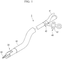
- FIG. 1 is an oblique view showing an overall configuration of a suturing device 1 according to the present embodiment.
- the suturing device 1 includes an elongated insertion portion 10 with flexibility, a suturing portion 20 disposed at a distal portion of the insertion portion 10, an operation portion 40 disposed at a proximal end portion of the insertion portion 10, and a grasping forceps (a suture thread grasping portion) 50 inserted through the insertion portion 10.
- the insertion portion 10 is formed from a coil or a resin and the like, and the insertion portion 10 is formed in a tubular shape.
- the insertion portion 10 has flexibility so that the insertion portion can follow the deformation of a channel of a flexible endoscope being used.
- a force of compression is applied to the insertion portion 10 along a direction of an axis line.
- the insertion portion 10 is preferred to have compression resistance by being configured using a coil or the like which is formed from metal wires.
- Fig. 2 is a cross section view of the suturing portion 20.
- the suturing portion 20 includes a tubular base body 21, a pressing stage 22 attached to the base body 21, a swaging member (a pressing member) 25 rotatably supported by the base body 21, and a driver 30 for driving the swaging member 25.
- the pressing stage 22 includes an installation surface 23 on which a pipe (an anchor) 100 is installed, the pipe 100 being fixed to the suture thread in a state in which the suture thread is inserted through.
- a V-shaped groove (a concave portion) 24 is formed on the installation surface 23 and is extended in a direction orthogonal to a direction of an axis line of the base body 21.
- the swaging member 25 includes a convex portion 26 disposed at a distal end portion thereof, a through hole 27 disposed at a middle portion thereof, and a driving projection 28 disposed at a proximal end side thereof.
- the swaging member is supported by the base body 21 and the pressing stage 22 while being relatively rotatable to the base body 21 and the pressing stage 22 since a rotation axis 21a disposed at the based boy 21 is inserted through the through hole 27.
- the convex portion 26 includes a ridgeline 26a extending in one direction.
- the swaging member 25 When the swaging member 25 is rotated about the rotation axis 21a as a rotary center so that the convex portion 26 approaches the V-shape groove 24, the direction in which the ridgeline 26a extends and the direction in which the V-shape groove 24 extends substantially coincide with each other, and the ridgeline 26a can enter the V-shape groove 24.
- a shaft hole (a penetrating portion) 29 is formed on an opposite side of the convex portion 26 with respect to the through hole 27, and the shaft hole 29 extends in a direction orthogonal to the through hole 27.
- the shaft hole 29 has openings at two ends thereof, and the shaft hole 29 has an internal diameter so that the grasping forceps 50 can be inserted through the shaft hole 29.
- the driving projection 28 projects at a position farther than the position of the shaft hole 29 with respect to the through hole 27.
- the driver 30 includes a rigid main body 31, and a wire (an operation member) 32 for driving the main body.
- the main body 31 has a suitable rigidness so that the swaging member 25 can be rotated when the main body gets over the driving projection 28 (described below).
- the wire 32 extends to the operation portion 40 via the inside of the insertion portion 10.
- the operation portion 40 includes a handle 41 for driving the driver 30, and a forceps port 42 into which the grasping forceps 50 is inserted.
- the handle 41 is connected by the wire 32, and the main body 31 of the driver 30 can be moved in a direction approaching the operation portion 40 when the handle 42 is held.
- the grasping forceps 50 includes a grasping portion 51 formed from a pair of jaws, and a slider 52 for opening and closing the grasping portion 51.
- a basic configuration of the grasping portion 50 is known to be the same with a configuration of a general grasping forceps used by being inserted through a flexible endoscope.
- the grasping forceps 50 has a dimension of being insertable into the forceps port 42, the shaft hole 29 of the swaging member 25, and the pipe 100, and the grasping forceps 50 is configured to be smaller than the general grasping forceps.
- the surgeon inserts a flexible endoscope into the luminal organs of a patient, and the surgeon performs threading procedures of inserting a suturing needle through the target tissue to make the suture thread through the target tissue by using a suturing unit configured by attaching the suturing needle to an end of the suture thread.
- the threading procedures can be performed using a known suturing apparatus used by inserting through the flexible endoscope.
- a suturing apparatus with a configuration of delivering and receiving the suturing needle between a pair of jaws, and a suturing apparatus with a configuration of driving a bent needle can be regarded as examples of the known suturing apparatus.
- the pipe 100 preferably has a radial dimension less than the ridgeline 26a and the V-shape groove 24.
- a material which is plastic deformable, such as a metal or a resin and the like, can be adopted as the material of the pipe, and a material with a high-level biocompatibility such as a titanium or a stainless steel and the like is more preferable .
- the pipe 100 is preferably installed in a manner that a direction of an axis line of the pipe 100 is orthogonal to the direction in which the V-shape groove 24 extends.
- the surgeon After the installation of the pipe 100, the surgeon inserts the suturing device 1 into the channel of the flexible endoscope. Subsequently, the surgeon inserts the grasping forceps 50 into the forceps port 42.
- the grasping forceps 50 may be inserted into the forceps port 42 before the insertion of the suturing device 1 into the flexible endoscope.
- the shaft hole 29 of the swaging member 25 and an internal cavity of the pipe 100 have a positional relationship of being coaxially positioned (a positional relationship of being substantially coaxially positioned is included, and so forth) and are arranged in a same straight line. Accordingly, the grasping forceps 50 inserted into the forceps port 42 can be easily inserted through the shaft hole 29 and the pipe 100 to cause the grasping portion 51 to project from the pipe 100.
- the surgeon moves the suturing device 1 in a state in which the grasping portion 51 projects from the pipe 100 to approach a target tissue St, and as shown in Fig. 3 , the surgeon uses the grasping portion 51 to grasp an end portion of the suture thread 105 which is placed in the target tissue St. Subsequently, the surgeon pulls the grasping forceps 50 proximally to the hand side to remove the grasping forceps 50 from the pipe 100 and the shaft hole 29. As shown in Fig. 4 , according to such an operation, the suture thread 105 is inserted through the pipe 100 and the shaft hole 29.
- the surgeon abuts the distal end of the suturing device 1 with the target tissue St while pulling the grasping forceps 50 which grasps the suture thread 105 proximally to the hand side.
- an incision of the target tissue St which should be closed by the suturing procedures is closed, and at the same time a tension applied to the target tissue St by the suture thread 105 is suitably adjusted to a desired amount.
- the surgeon keeps the tension and holds the handle 41 to drive the driver 30.
- the wire 32 is proximally pulled to the hand side and the main body 31 moves in a direction approaching the operation portion 40, thus the main body 31 contacts with the driving projection 28 of the swaging member 25.
- the main body 31 presses the driving projection 28.
- the swaging member 25 rotates about the rotation axis 21a as the rotary center, and the convex portion 26 directed to the installation surface 23 approaches and contacts with the pipe 100. According to this operation, the pipe 100 is sandwiched between the convex portion 26 and the installation surface 23. Further, as shown in Fig.
- a pressing force is applied to the pipe 100 from the ridgeline 26a so that the pipe 100 is folded along a portion with which the ridgeline 26a contacts regraded as a fold line.
- the pipe 100 is deformed and a part of the folded pipe 100 enters the V-groove 24.
- the pipe 100 is swaged so that the suture thread 105 inserted through the pipe 100 is in contact with the internal surface of the pipe 100 and the pipe 100 is fixed to the suture thread 105.
- Fig. 6 shows a view of the deformed pipe 100.
- the pipe 100 used to be a linear shape is swaged to be deformed into a substantial V-shape by being sandwiched between the pressing stage 22 and the swaging member 25 and being applied with a force from the convex portion 26, thus an angle is formed between an axis line X1 of a first region 102 positioned more distal than a folding line 101 with which the ridgeline contacts and an axis line X2 of a second region 103 positioned more proximal than the folding line 101, and the axis line X1 and the axis line X2 are nonparallel to each other.
- the pipe 100 fixed to the suture thread 105 cannot enter the target tissue St, as the same effects with the knot finally formed during the procedures of tying a surgeon' s knot, the pipe 100 prevents the suture thread 105 placed at the target tissue St from loosening. As a result, the suture thread 105 is suitably kept at the target tissue St in a state of being applied with a desired tension.
- the pipe 100 inserted through by the suture thread 105 is swaged to be deformed into the substantial V-shape, such that the axis line X1 of the first region 102 and the axis line X2 of the second region 103 at the proximal side are nonparallel to each other, for fixing the suture thread 105 and the pipe 100 with each other.
- the suture thread 105 is bent to be a substantial V-shape inside the pipe 100 following the axis line X1 and axis line X2, and the suture thread 105 is pressed by an inwardly projecting part of the internal surface of the pipe 100 at the folded position of the pipe 100.
- a large friction is generated between the suture thread 105 and the pipe 100 for more definitely fixing the suture thread 105 and the pipe 100 with each other, comparing to a general swaging performed while keeping the linear shape of the pipe.
- the surgeon without a high-level technique can also easily and definitely perform the procedures equivalent to the formation of a knot during the suturing procedures.
- the V-shape groove 24 and the convex portion 26 are formed at the pressing stage 22 and the swaging member 25 which are configured to sandwich and deform the pipe 100, respectively. Accordingly, the part of the pipe 100 pressed by the convex portion 26 can be suitably deformed into the V-shape groove 24 like dropping into the V-shape groove 24.
- the V-shaped groove 24 and the convex portion 26 can press the pipe 100 over the whole radial direction of the pipe 100, and thus the pipe 100 can be pressed and bent to be suitably deformed into the substantial V shape.
- the driver 30 for driving the swaging member 25 is driven by pulling the wire 32 connected to the operation portion 40.
- sine buckling and the like occurs easily when the operation member such as a wire and the like used for transmitting the operation force is pushed, it is not easy to suitably transmit the operation force by the pushing operation, however, the operation force can be suitably transmitted by the pulling operation.
- the operation force generated for driving the swaging member 25 is enough to easily perform the suturing procedures.
- Such effects are made more remarkable by enhancing the compression resistance of the insertion portion 10.
- the pipe 100 is arranged to be parallel to the longitudinal direction of the suturing device 1, thus the insertion of the grasping forceps 50 into the pipe 100 and the insertion of the suture thread 105 into the pipe 100 can be easily performed only by advancing and retracting the grasping forceps 50.
- the swaging member 25 includes the shaft hole 29, and the pipe 100 and the shaft hole 29 have the positional relationship of being arranged in the same straight line in the initial state, thus it is easy to insert the grasping forceps 50 through the shaft hole 29 and the pipe 100 by only advancing the grasping forceps 50 inserted into the insertion portion 10.
- the arrangement of the pipe 100 held on the installation surface 23 is not limited.
- the pipe 100 may be held by slightly pulling the driver 30 to the hand side to slightly sandwich the pipe 100 between the swaging member 25 and the pressing stage 22, and the pipe 100 may be temporarily held on the installation surface 23 using the adhesive agent and the like.
- the position of the pipe 100 on the installation surface 23 may be stabilized by arranging the pipe 100 in a shallow groove which is formed to be orthogonal to the V-shape groove 24 on the installation surface 23.
- the penetrating portion may be gutter-shaped that an internal surface of the penetrating portion is not continuous in a circumferential direction.
- a suturing device 151 according to the present embodiment includes a suturing portion which has a different configuration with that of the suturing device 1 according to the first embodiment.
- like reference numerals designate identical or corresponding components throughout the drawings and duplicate descriptions are omitted.
- Fig. 9 is a cross section view showing a suturing portion 160 of the suturing device 151.
- a part of an internal surface of a tubular base body 161 is formed to be flat and is regarded as an installation surface 161a.
- a screw shaft 162 having a screw groove cut on an external surface thereof is configured to penetrate the base body 161.
- Two pulleys 163 are fixed to both two end portions of the screw shaft 162 projecting from the external surface of the base body 161, respectively, and a wire 164 is wound about each of the pulleys 163 wherein the wire 164 is circularly connected.
- the wire 164 is attached to an operation pulley (not shown) of an operation portion (not shown) along the insertion portion 10.
- a rod-shaped guide 165 is installed inside the base body 161 to be parallel to the screw shaft 162.
- a swaging member 166 includes the same convex portion 26 according to the first embodiment.
- a first through hole 167 with a screw groove and a second through hole 168 without any screw groove are provided at a proximal side relative to the convex portion 26.
- the swaging member 166 is disposed inside the base body 161 in a manner such that the screw shaft 162 is inserted through the first through hole 167 by a screw fitting with the first through hole 167, and the guide 165 is inserted through the second through hole 168.
- the surgeon temporarily fixes the pipe 100 on the installation surface 161a by adhesive and the like, and performs the same procedures according to the first embodiment to insert the suture thread 105 through the pipe 100 using the grasping forceps 50 (not shown) .
- the surgeon rotates the operation pulley in a predetermined direction to pull the wire 164. Due to the operation, both the pulley 163 and the screw shaft 162 rotate. At this time, since the guide 165 is inserted through the swaging member 166, the screw shaft 162 and the swaging member 166 rotate relatively with each other rather than rotating integrally. As a result, the swaging member 166 moves upwardly to approach the installation surface 161a due to the screw fitting. Eventually, the convex portion 26 contacts with the pipe 100, and the pipe 100 is pressed to be deformed into the substantial V-shape.
- the suturing device 151 is configured to drive the swaging member 165 by pulling the wire 164, as the same with the suturing device 1 according to the first embodiment, even the insertion portion has a flexible structure, the suturing procedures can be easily performed.
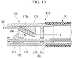
- Fig. 10 shows a modification of the present embodiment.
- Fig. 10 is a cross section view showing a suturing portion 180 of a suturing device 171 according to the present modification.
- a pressing stage 172 including an inclined surface 172a is installed inside the tubular base body 161.
- the inclined surface 172a functioning as the installation surface is directed to the distal end side of the suturing portion 180, and the pipe 100 is held on the inclined surface 172a by adhesive or engagement and the like.
- the swaging member 173 including a convex portion 174 is configured to be more distal than the pressing stage 172 in a state in which the convex portion 174 is directed to the side of the inclined surface 172a.
- a screw shaft 176 is inserted through a through hole 175 formed in the swaging member 173, and the swaging member 173 and the screw shaft 176 are screw fitted with each other.
- the screw shaft 176 extends parallely to an axis line of the base body 161.
- a proximal portion of the screw shaft 176 is connected to a distal end portion of a coil shaft 177 at a position relatively close to the base body 161 inside the insertion portion 10.
- the coil shaft 177 extends to an operation portion (not shown) through the inside of the insertion portion 10.
- the suturing device 171 of the present modification when the surgeon operates the operation portion to rotate the coil shaft 177 about the axis line thereof in a predetermined direction, the screw shaft 176 rotates about the axis line. As a result, the swaging member 173 relatively moves with respect to the screw shaft 176 and the convex portion 174 approaches the pipe 100 held by the pressing stage 172. Afterwards, the convex portion 174 contacts with the pipe 100 and presses the pipe 100 to deform the pipe 100 into the substantial V-shape.
- the coil shaft 177 has flexibility and can suitably follow the bending and the meandering of the insertion portion 10.
- the suturing device 171 According to the suturing device 171 according to the present modification, the same as the other embodiments, even the insertion portion has a flexible structure, and the suturing procedures can be easily performed.
- the screw shaft 176 and the coil shaft 177 functioning as a driver 178 are disposed inside the insertion portion 10 and configured to be along the longitudinal direction of the insertion portion 10, the miniaturization of the suturing portion is easier compared with the suturing device 151 described above.
- a concave portion may be formed on the inclined portion 172a of the suturing device 171 according to the present modification, and the concave portion disclosed in the other embodiments may be omitted.
- a groove formed with a curved bottom surface may be adopted instead of the V-shape groove in which the deepest portion extends linearly.
- the suturing device can easily perform the suturing procedures while being configured to include a flexible insertion portion.
Landscapes
- Health & Medical Sciences (AREA)
- Life Sciences & Earth Sciences (AREA)
- Surgery (AREA)
- Heart & Thoracic Surgery (AREA)
- Engineering & Computer Science (AREA)
- Biomedical Technology (AREA)
- Nuclear Medicine, Radiotherapy & Molecular Imaging (AREA)
- Medical Informatics (AREA)
- Molecular Biology (AREA)
- Animal Behavior & Ethology (AREA)
- General Health & Medical Sciences (AREA)
- Public Health (AREA)
- Veterinary Medicine (AREA)
- Rheumatology (AREA)
- Surgical Instruments (AREA)
Abstract
Description
- The present invention relates to a medical suturing device .
- Priority is claimed on Japanese Patent Application No.
2015-153844, filed on August 4, 2015 - Conventionally, various procedures are performed by using a flexible endoscope which is inserted luminal organs such as the gastrointestinal tract and the like. Generally, such procedures are performed by inserting an endoscopic treatment device through a channel formed in an insertion portion of the endoscope and then protruding a distal end of the treatment device out of a distal end of the insertion portion of the endoscope.
- Suturing procedures using a suture thread are regarded a difficult procedure. A series of suturing procedures include an operation of making the suture thread through a tissue, and an operation of tying a knot on the suture thread for continuing applying a predetermined tension on the tissue. The latter operation is considered to be more difficult and it is not easy to be performed using the treatment device.
- Instead of tying the knot, a method of fixing a suture fastener that is different from the suture thread to the suture thread in order to achieve the same function of the knot is proposed. A medical suturing apparatus disclosed in
Patent Document 1 is regarded as one of such suturing devices. - [Patent Document 1]
Japanese Unexamined Patent Application, First Publication No.H9-98976 - However, the medical suturing apparatus disclosed in
Patent Document 1 is configured to fix a suture fastener to the suture thread by advancing a pressing member to press the suture fastener. In a structure including a rigid insertion portion disclosed inPatent Document 1, such a configuration does not encounter any problem; however, in a treatment device configured to be inserted through a flexible endoscope and including a flexible insertion portion, this configuration is not realistic for various reasons. - The present invention has been made in view of the above circumstances and an object of the present invention is to provide a suturing device which can easily perform suturing procedures while being configured to include a flexible insertion portion.
- The present invention is a suturing device including a tubular insertion portion having flexibility; a suturing portion disposed at a distal end portion of the insertion portion, the suturing portion holding a tubular anchor through which a suture thread is insertable; an operation portion disposed at a proximal end portion of the insertion portion; and a suture thread grasping portion inserted through the insertion portion, the suture thread grasping portion being configured to be insertable through the anchor, wherein the suturing portion includes an installation surface on which the anchor is held; a pressing member including a convex portion for pressing the anchor, the convex portion being arranged to face the installation surface; and a driver connected to the operation portion, the driver configured to operate the pressing member, and wherein the anchor is sandwiched between the installation surface and the convex portion to be pressed, and thus the anchor is deformed to a substantial V shape by driving the driver.
- The convex portion may extend in one direction. A dimension in a longitudinal direction of the convex portion may be larger than an external diameter of the anchor. The installation surface may include a concave portion into which the convex portion is enterable.
- The driver may include an operation member connected to the operation portion, and the driver may be driven by pulling the operation member with the operation portion.
- The pressing member may include a penetrating portion through which the suture thread grasping portion is insertable. The pressing member may be configured such that an internal cavity of the anchor and the penetrating portion may be positioned on a straight line in an initial state before the driver is driven.
- According to the aspects described above, the suturing device can easily perform suturing procedures while being configured to include a flexible insertion portion.
-
-
Fig. 1 is an oblique view showing an overall configuration of a suturing device according to a first embodiment of the present invention. -
Fig. 2 is a cross section view showing a suturing portion of the suturing device according to the first embodiment of the present invention. -
Fig. 3 is a view showing an operation of the suturing device being used according to the first embodiment of the present invention. -
Fig. 4 is a view showing another operation of the suturing device being used according to the first embodiment of the present invention. -
Fig. 5 is a view showing another operation of the suturing device being used according to the first embodiment of the present invention. -
Fig. 6 is a view showing a deformed pipe. -
Fig. 7 is a view showing another operation of the suturing device being used according to the first embodiment of the present invention. -
Fig. 8 is a view showing a target tissue when the suturing procedures are finished. -
Fig. 9 is a cross section view showing a suturing portion of a suturing device according to a second embodiment of the present invention. -
Fig. 10 is a cross section view showing a modification of the suturing device according to the second embodiment of the present invention. - A first embodiment of the present invention will be described with reference to
Figs. 1 to 8 .Fig. 1 is an oblique view showing an overall configuration of asuturing device 1 according to the present embodiment. Thesuturing device 1 includes anelongated insertion portion 10 with flexibility, asuturing portion 20 disposed at a distal portion of theinsertion portion 10, anoperation portion 40 disposed at a proximal end portion of theinsertion portion 10, and a grasping forceps (a suture thread grasping portion) 50 inserted through theinsertion portion 10. - The
insertion portion 10 is formed from a coil or a resin and the like, and theinsertion portion 10 is formed in a tubular shape. Theinsertion portion 10 has flexibility so that the insertion portion can follow the deformation of a channel of a flexible endoscope being used. When thesuturing portion 20 is being driven (described below), a force of compression is applied to theinsertion portion 10 along a direction of an axis line. Accordingly, theinsertion portion 10 is preferred to have compression resistance by being configured using a coil or the like which is formed from metal wires. -
Fig. 2 is a cross section view of thesuturing portion 20. The suturingportion 20 includes atubular base body 21, apressing stage 22 attached to thebase body 21, a swaging member (a pressing member) 25 rotatably supported by thebase body 21, and adriver 30 for driving theswaging member 25. - The
pressing stage 22 includes aninstallation surface 23 on which a pipe (an anchor) 100 is installed, thepipe 100 being fixed to the suture thread in a state in which the suture thread is inserted through. A V-shaped groove (a concave portion) 24 is formed on theinstallation surface 23 and is extended in a direction orthogonal to a direction of an axis line of thebase body 21. - The
swaging member 25 includes aconvex portion 26 disposed at a distal end portion thereof, athrough hole 27 disposed at a middle portion thereof, and adriving projection 28 disposed at a proximal end side thereof. The swaging member is supported by thebase body 21 and thepressing stage 22 while being relatively rotatable to thebase body 21 and thepressing stage 22 since arotation axis 21a disposed at the basedboy 21 is inserted through thethrough hole 27. Theconvex portion 26 includes aridgeline 26a extending in one direction. When theswaging member 25 is rotated about therotation axis 21a as a rotary center so that theconvex portion 26 approaches the V-shape groove 24, the direction in which theridgeline 26a extends and the direction in which the V-shape groove 24 extends substantially coincide with each other, and theridgeline 26a can enter the V-shape groove 24. - In the
swaging member 25, a shaft hole (a penetrating portion) 29 is formed on an opposite side of theconvex portion 26 with respect to the throughhole 27, and theshaft hole 29 extends in a direction orthogonal to the throughhole 27. Theshaft hole 29 has openings at two ends thereof, and theshaft hole 29 has an internal diameter so that thegrasping forceps 50 can be inserted through theshaft hole 29. Thedriving projection 28 projects at a position farther than the position of theshaft hole 29 with respect to the throughhole 27. - The
driver 30 includes a rigidmain body 31, and a wire (an operation member) 32 for driving the main body. Themain body 31 has a suitable rigidness so that theswaging member 25 can be rotated when the main body gets over the driving projection 28 (described below). Thewire 32 extends to theoperation portion 40 via the inside of theinsertion portion 10. - As shown in
Fig. 1 , theoperation portion 40 includes ahandle 41 for driving thedriver 30, and aforceps port 42 into which thegrasping forceps 50 is inserted. Thehandle 41 is connected by thewire 32, and themain body 31 of thedriver 30 can be moved in a direction approaching theoperation portion 40 when thehandle 42 is held. - The
grasping forceps 50 includes agrasping portion 51 formed from a pair of jaws, and aslider 52 for opening and closing thegrasping portion 51. A basic configuration of the graspingportion 50 is known to be the same with a configuration of a general grasping forceps used by being inserted through a flexible endoscope. The graspingforceps 50 has a dimension of being insertable into theforceps port 42, theshaft hole 29 of the swagingmember 25, and thepipe 100, and the graspingforceps 50 is configured to be smaller than the general grasping forceps. - An operation of the
suturing device 1 having the configuration described above according to the present embodiment when being used will be described below. Firstly, the surgeon inserts a flexible endoscope into the luminal organs of a patient, and the surgeon performs threading procedures of inserting a suturing needle through the target tissue to make the suture thread through the target tissue by using a suturing unit configured by attaching the suturing needle to an end of the suture thread. The threading procedures can be performed using a known suturing apparatus used by inserting through the flexible endoscope. A suturing apparatus with a configuration of delivering and receiving the suturing needle between a pair of jaws, and a suturing apparatus with a configuration of driving a bent needle can be regarded as examples of the known suturing apparatus. - After the threading is finished, the surgeon separates the suturing needle from the suture thread and then removes the suturing apparatus used during the threading from the flexible endoscope. Subsequently, the surgeon installs the
pipe 100 on theinstallation surface 23 of thepressing stage 22. Thepipe 100 preferably has a radial dimension less than theridgeline 26a and the V-shape groove 24. A material which is plastic deformable, such as a metal or a resin and the like, can be adopted as the material of the pipe, and a material with a high-level biocompatibility such as a titanium or a stainless steel and the like is more preferable . Thepipe 100 is preferably installed in a manner that a direction of an axis line of thepipe 100 is orthogonal to the direction in which the V-shape groove 24 extends. - After the installation of the
pipe 100, the surgeon inserts thesuturing device 1 into the channel of the flexible endoscope. Subsequently, the surgeon inserts the graspingforceps 50 into theforceps port 42. The graspingforceps 50 may be inserted into theforceps port 42 before the insertion of thesuturing device 1 into the flexible endoscope. - As shown in
Fig. 2 , in an initial state of thesuturing device 1 before being driven by thedriver 30, theshaft hole 29 of the swagingmember 25 and an internal cavity of thepipe 100 have a positional relationship of being coaxially positioned (a positional relationship of being substantially coaxially positioned is included, and so forth) and are arranged in a same straight line. Accordingly, the graspingforceps 50 inserted into theforceps port 42 can be easily inserted through theshaft hole 29 and thepipe 100 to cause the graspingportion 51 to project from thepipe 100. - The surgeon moves the
suturing device 1 in a state in which the graspingportion 51 projects from thepipe 100 to approach a target tissue St, and as shown inFig. 3 , the surgeon uses the graspingportion 51 to grasp an end portion of thesuture thread 105 which is placed in the target tissue St. Subsequently, the surgeon pulls the graspingforceps 50 proximally to the hand side to remove the graspingforceps 50 from thepipe 100 and theshaft hole 29. As shown inFig. 4 , according to such an operation, thesuture thread 105 is inserted through thepipe 100 and theshaft hole 29. - Next, the surgeon abuts the distal end of the
suturing device 1 with the target tissue St while pulling the graspingforceps 50 which grasps thesuture thread 105 proximally to the hand side. According to this operation, an incision of the target tissue St which should be closed by the suturing procedures is closed, and at the same time a tension applied to the target tissue St by thesuture thread 105 is suitably adjusted to a desired amount. - Subsequently, the surgeon keeps the tension and holds the
handle 41 to drive thedriver 30. When thehandle 41 is held, thewire 32 is proximally pulled to the hand side and themain body 31 moves in a direction approaching theoperation portion 40, thus themain body 31 contacts with the drivingprojection 28 of the swagingmember 25. When thewire 32 is further pulled, themain body 31 presses the drivingprojection 28. As a result, the swagingmember 25 rotates about therotation axis 21a as the rotary center, and theconvex portion 26 directed to theinstallation surface 23 approaches and contacts with thepipe 100. According to this operation, thepipe 100 is sandwiched between theconvex portion 26 and theinstallation surface 23. Further, as shown inFig. 5 , a pressing force is applied to thepipe 100 from theridgeline 26a so that thepipe 100 is folded along a portion with which theridgeline 26a contacts regraded as a fold line. Thepipe 100 is deformed and a part of the foldedpipe 100 enters the V-groove 24. - Accordingly, the
pipe 100 is swaged so that thesuture thread 105 inserted through thepipe 100 is in contact with the internal surface of thepipe 100 and thepipe 100 is fixed to thesuture thread 105. -
Fig. 6 shows a view of thedeformed pipe 100. Thepipe 100 used to be a linear shape is swaged to be deformed into a substantial V-shape by being sandwiched between thepressing stage 22 and the swagingmember 25 and being applied with a force from theconvex portion 26, thus an angle is formed between an axis line X1 of afirst region 102 positioned more distal than afolding line 101 with which the ridgeline contacts and an axis line X2 of asecond region 103 positioned more proximal than thefolding line 101, and the axis line X1 and the axis line X2 are nonparallel to each other. - As shown in
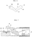
Fig. 7 , when thewire 32 is further pulled, themain body 31 gets over the drivingprojection 28 which is moved due to the rotation of the swagingmember 25, and themain body 31 moves to a position closer than that of the drivingprojection 28 with respect to theoperation portion 40. In this state, since the rotation of the swagingmember 25 is not restricted by thedriver 30, when thesuturing device 1 is retracted with respect to the target tissue St, both thepipe 100 and thesuture thread 105 are separated from the suturingportion 20. Finally, the unnecessary suture projecting from thepipe 100 is cut off and a series of the procedures are finished. - As shown in
Fig. 8 , since thepipe 100 fixed to thesuture thread 105 cannot enter the target tissue St, as the same effects with the knot finally formed during the procedures of tying a surgeon' s knot, thepipe 100 prevents thesuture thread 105 placed at the target tissue St from loosening. As a result, thesuture thread 105 is suitably kept at the target tissue St in a state of being applied with a desired tension. - As described above, according to the
suturing device 1 according to the present embodiment, thepipe 100 inserted through by thesuture thread 105 is swaged to be deformed into the substantial V-shape, such that the axis line X1 of thefirst region 102 and the axis line X2 of thesecond region 103 at the proximal side are nonparallel to each other, for fixing thesuture thread 105 and thepipe 100 with each other. Accordingly, thesuture thread 105 is bent to be a substantial V-shape inside thepipe 100 following the axis line X1 and axis line X2, and thesuture thread 105 is pressed by an inwardly projecting part of the internal surface of thepipe 100 at the folded position of thepipe 100. As a result, a large friction is generated between thesuture thread 105 and thepipe 100 for more definitely fixing thesuture thread 105 and thepipe 100 with each other, comparing to a general swaging performed while keeping the linear shape of the pipe. - According to the
suturing device 1, the surgeon without a high-level technique can also easily and definitely perform the procedures equivalent to the formation of a knot during the suturing procedures. - The V-
shape groove 24 and theconvex portion 26 are formed at thepressing stage 22 and the swagingmember 25 which are configured to sandwich and deform thepipe 100, respectively. Accordingly, the part of thepipe 100 pressed by theconvex portion 26 can be suitably deformed into the V-shape groove 24 like dropping into the V-shape groove 24. - Since the lengths of the V-shaped
groove 24 and theconvex portion 26 are larger than the external diameter of thepipe 100, the V-shapedgroove 24 and theconvex portion 26 can press thepipe 100 over the whole radial direction of thepipe 100, and thus thepipe 100 can be pressed and bent to be suitably deformed into the substantial V shape. - Further, the
driver 30 for driving the swagingmember 25 is driven by pulling thewire 32 connected to theoperation portion 40. In a flexible treatment device, sine buckling and the like occurs easily when the operation member such as a wire and the like used for transmitting the operation force is pushed, it is not easy to suitably transmit the operation force by the pushing operation, however, the operation force can be suitably transmitted by the pulling operation. - As a result, even the insertion portion is configured with a flexible structure, the operation force generated for driving the swaging
member 25 is enough to easily perform the suturing procedures. Such effects are made more remarkable by enhancing the compression resistance of theinsertion portion 10. - The
pipe 100 is arranged to be parallel to the longitudinal direction of thesuturing device 1, thus the insertion of the graspingforceps 50 into thepipe 100 and the insertion of thesuture thread 105 into thepipe 100 can be easily performed only by advancing and retracting the graspingforceps 50. - The swaging
member 25 includes theshaft hole 29, and thepipe 100 and theshaft hole 29 have the positional relationship of being arranged in the same straight line in the initial state, thus it is easy to insert the graspingforceps 50 through theshaft hole 29 and thepipe 100 by only advancing the graspingforceps 50 inserted into theinsertion portion 10. - According to the present embodiment, the arrangement of the
pipe 100 held on theinstallation surface 23 is not limited. For example, thepipe 100 may be held by slightly pulling thedriver 30 to the hand side to slightly sandwich thepipe 100 between the swagingmember 25 and thepressing stage 22, and thepipe 100 may be temporarily held on theinstallation surface 23 using the adhesive agent and the like. The position of thepipe 100 on theinstallation surface 23 may be stabilized by arranging thepipe 100 in a shallow groove which is formed to be orthogonal to the V-shape groove 24 on theinstallation surface 23. - Besides the shape of the
shaft hole 29 described above, the penetrating portion may be gutter-shaped that an internal surface of the penetrating portion is not continuous in a circumferential direction. - Next, a second embodiment of the present invention will be described with reference to
Figs. 9 and10 . Asuturing device 151 according to the present embodiment includes a suturing portion which has a different configuration with that of thesuturing device 1 according to the first embodiment. In the following description, it is to be noted that like reference numerals designate identical or corresponding components throughout the drawings and duplicate descriptions are omitted. -
Fig. 9 is a cross section view showing asuturing portion 160 of thesuturing device 151. In thesuturing portion 160, a part of an internal surface of atubular base body 161 is formed to be flat and is regarded as aninstallation surface 161a. Ascrew shaft 162 having a screw groove cut on an external surface thereof is configured to penetrate thebase body 161. Twopulleys 163 are fixed to both two end portions of thescrew shaft 162 projecting from the external surface of thebase body 161, respectively, and awire 164 is wound about each of thepulleys 163 wherein thewire 164 is circularly connected. Thewire 164 is attached to an operation pulley (not shown) of an operation portion (not shown) along theinsertion portion 10. - Inside the
base body 161, a rod-shapedguide 165 is installed to be parallel to thescrew shaft 162. - A swaging
member 166 includes the sameconvex portion 26 according to the first embodiment. A first throughhole 167 with a screw groove and a second throughhole 168 without any screw groove are provided at a proximal side relative to theconvex portion 26. The swagingmember 166 is disposed inside thebase body 161 in a manner such that thescrew shaft 162 is inserted through the first throughhole 167 by a screw fitting with the first throughhole 167, and theguide 165 is inserted through the second throughhole 168. - In the
suturing portion 160, all of thescrew shaft 162, thepulley 163, thewire 164, and theguide 165 corporately operate to realize the function as adriver 169. - When the
suturing device 151 is used, the surgeon temporarily fixes thepipe 100 on theinstallation surface 161a by adhesive and the like, and performs the same procedures according to the first embodiment to insert thesuture thread 105 through thepipe 100 using the grasping forceps 50 (not shown) . - Next, the surgeon rotates the operation pulley in a predetermined direction to pull the
wire 164. Due to the operation, both thepulley 163 and thescrew shaft 162 rotate. At this time, since theguide 165 is inserted through the swagingmember 166, thescrew shaft 162 and theswaging member 166 rotate relatively with each other rather than rotating integrally. As a result, the swagingmember 166 moves upwardly to approach theinstallation surface 161a due to the screw fitting. Eventually, theconvex portion 26 contacts with thepipe 100, and thepipe 100 is pressed to be deformed into the substantial V-shape. - When the
pipe 100 is deformed and fixed with respect to thesuture thread 105, the surgeon rotates the operation pulley in an opposite direction such that the swagingmember 166 moves downwardly. In such a state, the surgeon retracts thesuturing device 151, and thus thepipe 100 is separated from theinstallation surface 161a. - According to the present embodiment, since the
suturing device 151 is configured to drive the swagingmember 165 by pulling thewire 164, as the same with thesuturing device 1 according to the first embodiment, even the insertion portion has a flexible structure, the suturing procedures can be easily performed. -
Fig. 10 shows a modification of the present embodiment.Fig. 10 is a cross section view showing asuturing portion 180 of asuturing device 171 according to the present modification. Apressing stage 172 including aninclined surface 172a is installed inside thetubular base body 161. Theinclined surface 172a functioning as the installation surface is directed to the distal end side of thesuturing portion 180, and thepipe 100 is held on theinclined surface 172a by adhesive or engagement and the like. - The swaging
member 173 including aconvex portion 174 is configured to be more distal than thepressing stage 172 in a state in which theconvex portion 174 is directed to the side of theinclined surface 172a. Ascrew shaft 176 is inserted through a throughhole 175 formed in theswaging member 173, and theswaging member 173 and thescrew shaft 176 are screw fitted with each other. - The
screw shaft 176 extends parallely to an axis line of thebase body 161. A proximal portion of thescrew shaft 176 is connected to a distal end portion of acoil shaft 177 at a position relatively close to thebase body 161 inside theinsertion portion 10. Thecoil shaft 177 extends to an operation portion (not shown) through the inside of theinsertion portion 10. - According to the
suturing device 171 of the present modification, when the surgeon operates the operation portion to rotate thecoil shaft 177 about the axis line thereof in a predetermined direction, thescrew shaft 176 rotates about the axis line. As a result, the swagingmember 173 relatively moves with respect to thescrew shaft 176 and theconvex portion 174 approaches thepipe 100 held by thepressing stage 172. Afterwards, theconvex portion 174 contacts with thepipe 100 and presses thepipe 100 to deform thepipe 100 into the substantial V-shape. - The
coil shaft 177 has flexibility and can suitably follow the bending and the meandering of theinsertion portion 10. - According to the
suturing device 171 according to the present modification, the same as the other embodiments, even the insertion portion has a flexible structure, and the suturing procedures can be easily performed. - Since the
screw shaft 176 and thecoil shaft 177 functioning as adriver 178 are disposed inside theinsertion portion 10 and configured to be along the longitudinal direction of theinsertion portion 10, the miniaturization of the suturing portion is easier compared with thesuturing device 151 described above. - The embodiments of the invention have been described above with reference to the drawings, but specific structures of the invention are not limited to the embodiments and may include various modifications without departing from the scope of the invention.
- For example, a concave portion may be formed on the
inclined portion 172a of thesuturing device 171 according to the present modification, and the concave portion disclosed in the other embodiments may be omitted. - Regarding the configuration of the concave portion, a groove formed with a curved bottom surface may be adopted instead of the V-shape groove in which the deepest portion extends linearly.
- According to each embodiment described above, the suturing device can easily perform the suturing procedures while being configured to include a flexible insertion portion.
-
- 1, 151, 171 suturing device
- 10 insertion portion
- 20, 160, 180 suturing portion
- 23, 161a, 172a installation surface
- 24 V-shape groove (concave portion)
- 25, 166, 173 swaging member (pressing member)
- 26, 174 convex portion
- 29 shaft hole (penetrating portion)
- 30, 169, 178 driver
- 32, 164 wire (operation member)
- 40 operation portion
- 50 grasping forceps (suture thread grasping portion)
- 100 pipe (anchor)
- 105 suture thread
Claims (4)
- A suturing device, comprising:a tubular insertion portion having flexibility;a suturing portion disposed at a distal end portion of the insertion portion, the suturing portion holding a tubular anchor through which a suture thread is insertable;an operation portion disposed at a proximal end portion of the insertion portion; anda suture thread grasping portion inserted through the insertion portion, the suture thread grasping portion being configured to be insertable through the anchor,wherein the suturing portion includesan installation surface on which the anchor is held;a pressing member including a convex portion for pressing the anchor, the convex portion being arranged to face the installation surface; anda driver connected to the operation portion, the driver configured to operate the pressing member, andwherein the anchor is sandwiched between the installation surface and the convex portion to be pressed, and thus the anchor is deformed to a substantial V shape by driving the driver.
- The suturing device according to claim 1,
wherein the convex portion extends in one direction,
wherein a dimension in a longitudinal direction of the convex portion is larger than an external diameter of the anchor, and
wherein the installation surface includes a concave portion into which the convex portion is enterable. - The suturing device according to claim 1,
wherein the driver includes an operation member connected to the operation portion, and
wherein the driver is driven by pulling the operation member with the operation portion. - The suturing device according to claim 1,
wherein the pressing member includes a penetrating portion through which the suture thread grasping portion is insertable, and
wherein the pressing member is configured such that an internal cavity of the anchor and the penetrating portion are positioned on a straight line in an initial state before the driver is driven.
Applications Claiming Priority (2)
| Application Number | Priority Date | Filing Date | Title |
|---|---|---|---|
| JP2015153844 | 2015-08-04 | ||
| PCT/JP2016/066870 WO2017022326A1 (en) | 2015-08-04 | 2016-06-07 | Suture device |
Publications (2)
| Publication Number | Publication Date |
|---|---|
| EP3332714A1 true EP3332714A1 (en) | 2018-06-13 |
| EP3332714A4 EP3332714A4 (en) | 2019-05-15 |
Family
ID=57943832
Family Applications (1)
| Application Number | Title | Priority Date | Filing Date |
|---|---|---|---|
| EP16832605.6A Withdrawn EP3332714A4 (en) | 2015-08-04 | 2016-06-07 | Suture device |
Country Status (5)
| Country | Link |
|---|---|
| US (1) | US10792030B2 (en) |
| EP (1) | EP3332714A4 (en) |
| JP (1) | JP6180694B2 (en) |
| CN (1) | CN107920814A (en) |
| WO (1) | WO2017022326A1 (en) |
Families Citing this family (6)
| Publication number | Priority date | Publication date | Assignee | Title |
|---|---|---|---|---|
| US11304691B2 (en) | 2016-11-13 | 2022-04-19 | Anchora Medical Ltd. | Minimally-invasive tissue suturing device |
| CN112206022B (en) * | 2019-07-10 | 2024-07-02 | 杭州德晋医疗科技有限公司 | Intervention type remote locking and thread cutting device |
| CN113040843B (en) * | 2019-12-26 | 2024-08-16 | 杭州德晋医疗科技有限公司 | Tension driving type locking device |
| CN113040844B (en) * | 2019-12-26 | 2024-08-16 | 杭州德晋医疗科技有限公司 | Insertion type locking device |
| WO2021185323A1 (en) * | 2020-03-20 | 2021-09-23 | 杭州德晋医疗科技有限公司 | Forward-pushing release type suture line locking device |
| CN113491547B (en) * | 2020-03-20 | 2026-03-31 | 杭州德晋医疗科技有限公司 | Forward-release suture locking device |
Family Cites Families (15)
| Publication number | Priority date | Publication date | Assignee | Title |
|---|---|---|---|---|
| JPH0998976A (en) | 1995-10-06 | 1997-04-15 | Olympus Optical Co Ltd | Suturing instrument for medical use |
| US6077277A (en) * | 1999-04-05 | 2000-06-20 | Starion Instruments, Inc. | Suture welding device |
| US6997931B2 (en) * | 2001-02-02 | 2006-02-14 | Lsi Solutions, Inc. | System for endoscopic suturing |
| US7235086B2 (en) * | 2001-02-02 | 2007-06-26 | Lsi Solutions, Inc. | Crimping instrument with motion limiting feature |
| US7736372B2 (en) * | 2003-11-13 | 2010-06-15 | Usgi Medical, Inc. | Apparatus and methods for endoscopic suturing |
| US7736378B2 (en) * | 2004-05-07 | 2010-06-15 | Usgi Medical, Inc. | Apparatus and methods for positioning and securing anchors |
| US7390329B2 (en) * | 2004-05-07 | 2008-06-24 | Usgi Medical, Inc. | Methods for grasping and cinching tissue anchors |
| EP1859743B1 (en) | 2005-03-17 | 2015-08-05 | Olympus Corporation | Suture instrument |
| JPWO2007037335A1 (en) * | 2005-09-28 | 2009-04-09 | オリンパスメディカルシステムズ株式会社 | Suture device |
| US7875041B2 (en) | 2005-09-28 | 2011-01-25 | Olympus Medical Systems Corp. | Suturing method for penetrating hole |
| US8262675B2 (en) * | 2008-10-29 | 2012-09-11 | Ethicon Endo-Surgery, Inc. | Methods and devices for applying multiple suture anchors |
| US8398680B2 (en) * | 2010-04-07 | 2013-03-19 | Lsi Solutions, Inc. | Bioabsorbable magnesium knots for securing surgical suture |
| US9017347B2 (en) * | 2011-12-22 | 2015-04-28 | Edwards Lifesciences Corporation | Suture clip deployment devices |
| US10016193B2 (en) * | 2013-11-18 | 2018-07-10 | Edwards Lifesciences Ag | Multiple-firing crimp device and methods for using and manufacturing same |
| JPWO2014030544A1 (en) * | 2012-08-24 | 2016-07-28 | オリンパスメディカルシステムズ株式会社 | Suture device |
-
2016
- 2016-06-07 CN CN201680045231.1A patent/CN107920814A/en active Pending
- 2016-06-07 WO PCT/JP2016/066870 patent/WO2017022326A1/en not_active Ceased
- 2016-06-07 JP JP2017526614A patent/JP6180694B2/en active Active
- 2016-06-07 EP EP16832605.6A patent/EP3332714A4/en not_active Withdrawn
-
2018
- 2018-02-01 US US15/886,348 patent/US10792030B2/en active Active
Also Published As
| Publication number | Publication date |
|---|---|
| CN107920814A (en) | 2018-04-17 |
| JP6180694B2 (en) | 2017-08-16 |
| EP3332714A4 (en) | 2019-05-15 |
| JPWO2017022326A1 (en) | 2017-08-10 |
| US20180153539A1 (en) | 2018-06-07 |
| WO2017022326A1 (en) | 2017-02-09 |
| US10792030B2 (en) | 2020-10-06 |
Similar Documents
| Publication | Publication Date | Title |
|---|---|---|
| US10792030B2 (en) | Suturing device | |
| JP7235811B2 (en) | Device for approximating multiple tissue edges | |
| US10448946B2 (en) | Endoscopic suture cinch | |
| JP5073333B2 (en) | Surgical fasteners and surgical instruments | |
| US7037315B2 (en) | Surgical suturing instrument and method of use | |
| US20170086817A1 (en) | Endoscopic Suture Cinch System | |
| US7131980B1 (en) | Surgical suturing instrument and method of use | |
| US20020128666A1 (en) | Surgical suturing instrument and method of use | |
| US20040092967A1 (en) | Surgical suturing instrument and method of use | |
| US20040194790A1 (en) | Tissue reconfiguration | |
| MX2013012439A (en) | Advance suture passer. | |
| JP2006508781A (en) | Tissue retractor device and method of using the same | |
| US20090259232A1 (en) | Suture device | |
| EP2617367B1 (en) | Suture thread pushing apparatus and suture thread pushing system | |
| CN112261909A (en) | Suture threading device and method of use | |
| JP4256874B2 (en) | Tissue retractor device | |
| EP3323365A1 (en) | Tissue-suturing system |
Legal Events
| Date | Code | Title | Description |
|---|---|---|---|
| STAA | Information on the status of an ep patent application or granted ep patent |
Free format text: STATUS: THE INTERNATIONAL PUBLICATION HAS BEEN MADE |
|
| PUAI | Public reference made under article 153(3) epc to a published international application that has entered the european phase |
Free format text: ORIGINAL CODE: 0009012 |
|
| STAA | Information on the status of an ep patent application or granted ep patent |
Free format text: STATUS: REQUEST FOR EXAMINATION WAS MADE |
|
| 17P | Request for examination filed |
Effective date: 20180220 |
|
| AK | Designated contracting states |
Kind code of ref document: A1 Designated state(s): AL AT BE BG CH CY CZ DE DK EE ES FI FR GB GR HR HU IE IS IT LI LT LU LV MC MK MT NL NO PL PT RO RS SE SI SK SM TR |
|
| AX | Request for extension of the european patent |
Extension state: BA ME |
|
| DAV | Request for validation of the european patent (deleted) | ||
| DAX | Request for extension of the european patent (deleted) | ||
| A4 | Supplementary search report drawn up and despatched |
Effective date: 20190417 |
|
| RIC1 | Information provided on ipc code assigned before grant |
Ipc: A61B 17/04 20060101AFI20190411BHEP |
|
| STAA | Information on the status of an ep patent application or granted ep patent |
Free format text: STATUS: THE APPLICATION HAS BEEN WITHDRAWN |
|
| 18W | Application withdrawn |
Effective date: 20190807 |