EP3332689A1 - Pen-type medical fluorescent imaging device and system for aligning multiple fluorescent images using same - Google Patents
Pen-type medical fluorescent imaging device and system for aligning multiple fluorescent images using same Download PDFInfo
- Publication number
- EP3332689A1 EP3332689A1 EP16832412.7A EP16832412A EP3332689A1 EP 3332689 A1 EP3332689 A1 EP 3332689A1 EP 16832412 A EP16832412 A EP 16832412A EP 3332689 A1 EP3332689 A1 EP 3332689A1
- Authority
- EP
- European Patent Office
- Prior art keywords
- fluorescent
- image
- glioma
- vascular
- pen
- Prior art date
- Legal status (The legal status is an assumption and is not a legal conclusion. Google has not performed a legal analysis and makes no representation as to the accuracy of the status listed.)
- Granted
Links
Images



Classifications
-
- G—PHYSICS
- G06—COMPUTING OR CALCULATING; COUNTING
- G06T—IMAGE DATA PROCESSING OR GENERATION, IN GENERAL
- G06T7/00—Image analysis
- G06T7/30—Determination of transform parameters for the alignment of images, i.e. image registration
- G06T7/37—Determination of transform parameters for the alignment of images, i.e. image registration using transform domain methods
-
- A—HUMAN NECESSITIES
- A61—MEDICAL OR VETERINARY SCIENCE; HYGIENE
- A61B—DIAGNOSIS; SURGERY; IDENTIFICATION
- A61B1/00—Instruments for performing medical examinations of the interior of cavities or tubes of the body by visual or photographical inspection, e.g. endoscopes; Illuminating arrangements therefor
- A61B1/04—Instruments for performing medical examinations of the interior of cavities or tubes of the body by visual or photographical inspection, e.g. endoscopes; Illuminating arrangements therefor combined with photographic or television appliances
- A61B1/043—Instruments for performing medical examinations of the interior of cavities or tubes of the body by visual or photographical inspection, e.g. endoscopes; Illuminating arrangements therefor combined with photographic or television appliances for fluorescence imaging
-
- A—HUMAN NECESSITIES
- A61—MEDICAL OR VETERINARY SCIENCE; HYGIENE
- A61B—DIAGNOSIS; SURGERY; IDENTIFICATION
- A61B5/00—Measuring for diagnostic purposes; Identification of persons
- A61B5/0059—Measuring for diagnostic purposes; Identification of persons using light, e.g. diagnosis by transillumination, diascopy, fluorescence
- A61B5/0071—Measuring for diagnostic purposes; Identification of persons using light, e.g. diagnosis by transillumination, diascopy, fluorescence by measuring fluorescence emission
-
- A—HUMAN NECESSITIES
- A61—MEDICAL OR VETERINARY SCIENCE; HYGIENE
- A61B—DIAGNOSIS; SURGERY; IDENTIFICATION
- A61B5/00—Measuring for diagnostic purposes; Identification of persons
- A61B5/74—Details of notification to user or communication with user or patient; User input means
- A61B5/742—Details of notification to user or communication with user or patient; User input means using visual displays
- A61B5/7425—Displaying combinations of multiple images regardless of image source, e.g. displaying a reference anatomical image with a live image
-
- A—HUMAN NECESSITIES
- A61—MEDICAL OR VETERINARY SCIENCE; HYGIENE
- A61K—PREPARATIONS FOR MEDICAL, DENTAL OR TOILETRY PURPOSES
- A61K49/00—Preparations for testing in vivo
- A61K49/001—Preparation for luminescence or biological staining
- A61K49/0013—Luminescence
- A61K49/0017—Fluorescence in vivo
- A61K49/0019—Fluorescence in vivo characterised by the fluorescent group, e.g. oligomeric, polymeric or dendritic molecules
- A61K49/0021—Fluorescence in vivo characterised by the fluorescent group, e.g. oligomeric, polymeric or dendritic molecules the fluorescent group being a small organic molecule
- A61K49/0032—Methine dyes, e.g. cyanine dyes
- A61K49/0034—Indocyanine green, i.e. ICG, cardiogreen
-
- G—PHYSICS
- G06—COMPUTING OR CALCULATING; COUNTING
- G06T—IMAGE DATA PROCESSING OR GENERATION, IN GENERAL
- G06T7/00—Image analysis
- G06T7/10—Segmentation; Edge detection
- G06T7/12—Edge-based segmentation
-
- G—PHYSICS
- G06—COMPUTING OR CALCULATING; COUNTING
- G06T—IMAGE DATA PROCESSING OR GENERATION, IN GENERAL
- G06T7/00—Image analysis
- G06T7/10—Segmentation; Edge detection
- G06T7/174—Segmentation; Edge detection involving the use of two or more images
-
- A—HUMAN NECESSITIES
- A61—MEDICAL OR VETERINARY SCIENCE; HYGIENE
- A61B—DIAGNOSIS; SURGERY; IDENTIFICATION
- A61B2560/00—Constructional details of operational features of apparatus; Accessories for medical measuring apparatus
- A61B2560/04—Constructional details of apparatus
- A61B2560/0406—Constructional details of apparatus specially shaped apparatus housings
- A61B2560/0418—Pen-shaped housings
-
- A—HUMAN NECESSITIES
- A61—MEDICAL OR VETERINARY SCIENCE; HYGIENE
- A61B—DIAGNOSIS; SURGERY; IDENTIFICATION
- A61B2562/00—Details of sensors; Constructional details of sensor housings or probes; Accessories for sensors
- A61B2562/02—Details of sensors specially adapted for in-vivo measurements
- A61B2562/0233—Special features of optical sensors or probes classified in A61B5/00
-
- G—PHYSICS
- G06—COMPUTING OR CALCULATING; COUNTING
- G06T—IMAGE DATA PROCESSING OR GENERATION, IN GENERAL
- G06T2207/00—Indexing scheme for image analysis or image enhancement
- G06T2207/10—Image acquisition modality
- G06T2207/10016—Video; Image sequence
-
- G—PHYSICS
- G06—COMPUTING OR CALCULATING; COUNTING
- G06T—IMAGE DATA PROCESSING OR GENERATION, IN GENERAL
- G06T2207/00—Indexing scheme for image analysis or image enhancement
- G06T2207/10—Image acquisition modality
- G06T2207/10064—Fluorescence image
-
- G—PHYSICS
- G06—COMPUTING OR CALCULATING; COUNTING
- G06T—IMAGE DATA PROCESSING OR GENERATION, IN GENERAL
- G06T2207/00—Indexing scheme for image analysis or image enhancement
- G06T2207/30—Subject of image; Context of image processing
- G06T2207/30004—Biomedical image processing
- G06T2207/30096—Tumor; Lesion
-
- G—PHYSICS
- G06—COMPUTING OR CALCULATING; COUNTING
- G06T—IMAGE DATA PROCESSING OR GENERATION, IN GENERAL
- G06T2207/00—Indexing scheme for image analysis or image enhancement
- G06T2207/30—Subject of image; Context of image processing
- G06T2207/30004—Biomedical image processing
- G06T2207/30101—Blood vessel; Artery; Vein; Vascular
Definitions
- the present invention relates to a medical fluorescent imaging device and a system for aligning multiple fluorescent images using the same.
- MRI technology is a method of obtaining anatomical, physiological, and biochemical information images of a body by using a phenomenon in which the spinning of hydrogen atoms is relaxed.
- MRI technology is an excellent diagnostic imaging technology that is not invasive towards body organs of a person or an animal and makes it possible to capture images thereof in real time.
- 5-aminolevulinic acid which is a fluorescent luminescent material for marking tumors and blood vessels, is injected into the human body and then fluoresces due to generation of protoporphyrin IX (PpIX) derived from a material transformation process caused by metabolism in the body. With such a reaction process, 5-ALA serves as a target fluorescence marker targeting only cancer cells.
- ICG indocyanine green
- 5-ALA is used to cause cancer cells to fluoresce
- ICG is used to cause blood vessels to fluoresce
- the present invention is directed to a fluorescent imaging device capable of detecting and showing the positions of blood vessels and the position of a glioma at the same time for a patient's safety and ease of surgery.
- the present invention is also directed to a system for aligning multiple fluorescent images which makes it possible for an operator to accurately and easily check the positions and connections of a tumor and blood vessels by acquiring multiple fluorescent images in which the positions of the blood vessels and the boundary of a glioma are marked to luminesce due to multiple fluorescent materials, and by aligning and displaying the acquired multiple fluorescent images in real time.
- a pen-type medical fluorescent imaging device including: a probe configured to extend in a longitudinal direction and include an image capturing section at one end; a plurality of light sources configured to be arranged to surround the image capturing section; and a controller configured to control the light sources.
- the light sources include a first light source configured to emit light of a first wavelength range so that blood vessels are marked by a first fluorescent material, and a second light source configured to emit light of a second wavelength range so that a glioma is marked by a second fluorescent material.
- the first and second light sources are selectively controlled by the controller.
- a system for aligning multiple fluorescent images including: the pen-type medical fluorescent imaging device; a fluorescent multi-image acquirer configured to acquire an actual image of a target part, a fluorescent vascular image in which blood vessels are marked by the first fluorescent material, and a fluorescent glioma image in which a glioma is marked by the second fluorescent material; a blood vessel extractor configured to extract a vascular shape from the acquired fluorescent vascular image; a glioma image processor configured to process the acquired fluorescent glioma image so that a boundary of the glioma becomes distinct; a fluorescent multi-image aligner configured to align the extracted fluorescent vascular image and fluorescent glioma image in real time; and a fluorescent image display configured to display a fluorescent multi-image in which the fluorescent vascular image and the fluorescent glioma image are aligned.
- the present invention relates to a pen-type medical fluorescent imaging device capable of detecting and showing the position of a glioma and the positions of blood vessels at the same time for a patient's safety and ease of surgery.
- a pen type denotes a small pen shape that may be conveniently and freely used with a hand like a pen, which is a writing instrument.
- a probe 110 may be formed in a pen shape.
- the pen-type medical fluorescent imaging device includes: a probe that extends in a longitudinal direction and includes an image capturing section at one end; a plurality of light sources that are arranged to surround the image capturing section; and a controller that controls the light sources.
- the light sources include a first light source that emits light of a first wavelength range so that blood vessels are marked by a first fluorescent material, and a second light source that emits light of a second wavelength range so that a glioma is marked by a second fluorescent material.
- the first and second light sources are selectively controlled by the controller.
- the light sources may include filters.
- the first light source may include a first filter
- the second light source may include a second filter.
- the first fluorescent material may include indocyanine green (ICG)
- the second fluorescent material may include one of 5-aminolevulinic acid (5-ALA) and protoporphyrin IX (PpIX) converted from 5-ALA.
- the light sources may include a third light source that emits white light.
- the first wavelength range may be 750 nm to 800 nm
- the second wavelength range may be 350 nm to 450 nm.
- the probe is formed of a flexible material.
- the present invention relates to a system for aligning multiple fluorescent images.
- the system includes: the pen-type medical fluorescent imaging device; a fluorescent multi-image acquirer that acquires an actual image of a target part, a fluorescent vascular image in which blood vessels are marked by the first fluorescent material, and a fluorescent glioma image in which a glioma is marked by the second fluorescent material; a blood vessel extractor that extracts a vascular shape from the acquired fluorescent vascular image; a glioma image processor that processes the acquired fluorescent glioma image so that the boundary of the glioma becomes distinct; a fluorescent multi-image aligner that aligns the extracted fluorescent vascular image and the fluorescent glioma image in real time; and a fluorescent image display that displays a fluorescent multi-image in which the fluorescent vascular image and the fluorescent glioma image are aligned.
- the fluorescent multi-image acquirer includes a fluorescent vascular shape image acquirer that acquires the fluorescent vascular image in which the positions of the blood vessels are marked by the first fluorescent material, and a fluorescent glioma image acquirer that acquires the fluorescent glioma image in which the position of the glioma is marked by the second fluorescent material.
- the fluorescent multi-image acquirer may acquire transformation parameters corresponding to the highest similarity by measuring pixel value-based similarities of a moving image with respect to the actual image, and match the moving image to the actual image by performing two-dimensional (2D) centered similarity registration based on the acquired transformation parameters so that coordinate errors between the actaul image and the moving image are minimized, and the moving image may be one of the fluorescent vascular image and the fluorescent glioma image.
- the fluorescent image display may display at least one of the actual image, the fluorescent vascular image, the fluorescent glioma image, and the fluorescent multi-image according to a selection of an operator or a user.
- the fluorescent image display may set individual opacity values of the actual image, the fluorescent vascular image, the fluorescent glioma image, and the fluorescent multi-image to simultaneously display a plurality of images overlapping with each other, and may adjust the opacity values of the individual images to display only a specific image as necessary.
- the pen-type medical fluorescent imaging device may include a transmitter capable of transmitting the actual image, the fluorescent vascular image, and the fluorescent glioma image captured by the image capturing section to the fluorescent multi-image acquirer through wireless communication.
- FIG. 1 is a perspective view of a pen-type medical fluorescent imaging device according to the present invention
- FIG. 2 is a front view of the pen-type medical fluorescent imaging device according to the present invention
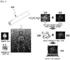
- FIG. 3 is a conceptual diagram for facilitating understanding of overall operation of a system for aligning multiple fluorescent images according to the present invention
- FIG. 4 is a block diagram of the system for aligning multiple fluorescent images according to the present invention.
- a pen-type medical fluorescent imaging device and a system for aligning multiple fluorescent images according to the present invention will be described below with reference to FIGS. 1 to 4 and exemplary embodiments.
- the present invention provides a pen-type medical fluorescent imaging device 100 capable of detecting and showing the positions of blood vessels and the position of a glioma at the same time for a patient's safety and ease of surgery.
- the medical fluorescent imaging device 100 of the present invention is formed as a pen type, and includes the probe 110 extending in a longitudinal direction and an image capturing section 120 and light sources 130 at one end of the probe 110.
- a pen type denotes a small pen shape that may be conveniently and freely used with a hand like a pen, which is a writing instrument.
- the probe 110 may be formed in a pen shape.
- the probe 110 may include the image capturing section 120 and the light sources 130 at the end, and the light sources 130 may be plural in number to surround the image capturing section 120.
- the light sources 130 may include a first light source 131 and a second light source 132.
- the first light source 131 may emit light of a first wavelength range so that blood vessels are marked by a first fluorescent material
- the second light source 132 may emit light of a second wavelength range so that a glioma is marked by a second fluorescent material.
- the light sources 130 may be light-emitting diode (LED) lamps, and may preferably be near-infrared LED lamps. The number of LED lamps that emit light may be adjusted according to the size and shape of a target part.
- LED light-emitting diode
- the image capturing section 120 of the present invention captures an image of a target part, and may be a general camera for capturing an actual image of a target part, a fluorescent vascular image in which blood vessels are marked by the first fluorescent material, and a fluorescent glioma image in which a glioma is marked by the second fluorescent material.
- a digital camera or a near infrared ray camera capable of capturing and outputting or storing an image in real time may be used as the image capturing section 120.
- a charge coupled device (CCD) or complementary metal-oxide semiconductor (CMOS) camera may be used, and a CCD or CMOS camera having a resolution of megapixel level or greater may preferably be used.
- CCD charge coupled device
- CMOS complementary metal-oxide semiconductor
- Such a camera with megapixel level resolution or greater may be used to acquire a vascular and/or glioma image at high resolution and to observe blood vessels in real time (it is possible to acquire images of 30 frames or more per second). Therefore, convenience for doctors and patients is improved, and it is possible to rapidly and easily observe blood vessels and/or a glioma during a medical examination and surgery of a patient.
- the light sources 130 and the image capturing section 120 are installed at a front end of the probe 110 such that loss of light and image quality may be reduced.
- the fluorescent imaging device 100 of the present invention may include a controller 140 that controls the light sources 130.
- the first light source 131 and the second light source 132 may be selectively controlled by the controller 140 to emit light.
- the controller 140 may be a conventional switch, and may be supplied with current from a power supply and may turn on or off the light sources 130.
- the controller 140 that controls the first light source 131 and the second light source 132 may be a first switch 141 and a second switch 142.
- ICG, 5-ALA, and the like which are near-infrared fluorescent materials, may be used as fluorescent materials.
- the first fluorescent material may be ICG
- the second fluorescent material may be 5-ALA.
- ICG which is efficient in terms of detecting the positions of a patient's blood vessels and lymph nodes, is a fluorescent material that has been used since 1957 and has few side effects.
- ICG When injected into a patient, ICG is combined with plasma protein, and when light in a range of 750 nm to 800 nm is transmitted, ICG radiates fluorescent light having a fluorescence peak value of 845 nm.
- 5-ALA which is efficient in terms of detecting the position of a glioma, has a fluorescence peak value of 635 nm and radiates fluorescent light when light of about 400 nm is transmitted to PpIX converted in cells (it is also possible to use radiated light of about 405 nm). Using this property, it is possible to distinguish between normal tissue and a malignant glioma.
- the use of 5-ALA increases a success rate of complete removal of a malignant glioma about 1.4 times, and reduces a malignant glioma which is not removed to 1/16 of its size, and is thus effective in terms of preventing recurrence of the malignant glioma.
- the medical fluorescent imaging device 100 of the present invention may emit light of various wavelengths through the light sources 130, and a laser, an LED, and the like may be used as light sources.
- the light sources 130 may include a filter 150, which filters an excitation wavelength band at which multiple fluorescent materials distributed in a target body such as a human body are excited and filters a light-emitting wavelength band at which light is emitted from the excited multiple fluorescent materials.
- the filter 150 may be provided to filter an excitation wavelength band and a light-emitting wavelength band that are different from each other.
- the first light source 131 may include a first filter
- the second light source 132 may include a second filter
- ICG intravenously injected into a patient and 5-ALA is ingested by the patient
- light in a range of 750 nm to 800 nm may be transmitted to a treatment area of the patient through the first light source of the medical fluorescent imaging device 100 of the present invention.
- ICG combined with plasma protein in the target body may radiate fluorescent light having a peak value of 845 nm.
- fluorescent light having a peak value of 635 nm may be radiated by PpIX distributed to a glioma.
- the first wavelength range may be 750 nm to 800 nm
- the second wavelength range may be 350 nm to 450 nm.
- the medical fluorescent imaging device 100 of the present invention may include a third light source 133 that may radiate white light.
- the controller 140 for controlling the third light source 133 may be a third switch 143.
- the third light source 133 may be used in diagnosis of a patient by a doctor, and medical personnel may use the third light source 133 as a substitute for a medical pen light.
- a pen light is used by a doctor to diagnose a patient.
- a pen light As a light formed in a pen shape, a pen light enables a user to conveniently carry it around or turn it on in the dark to identify objects.
- the medical fluorescent imaging device 100 of the present invention may include a battery for power supply that is installed so as to be replaceable in the probe 110.
- a clip (not shown) for fixing the medical fluorescent imaging device 100 to a doctor's gown may be included.
- the medical fluorescent imaging device 100 having such a configuration including the third light source 133 may be used in a doctor's office, a ward, etc. to emit light on dim areas of a patient's body such as the mouth, nose, ears, etc., that natural light, general lighting, etc. cannot reach and to examine an affected area or used to emit light to an eye and check a pupillary reflex.
- the probe 110 of the present invention may be formed of a flexible material.
- a user may change the position of a total cross section irradiated by the light sources 130 as necessary, and may easily emit light to a part to be examined and capture an image of the part, such that the convenience and accuracy of work are improved.
- the probe 110 may be formed of a metal or a synthetic resin such as polypropylene (PP), polyethylene (PE), nylon, or the like, and a bellow pipe may be formed as a particular aspect.
- any flexible material fulfilling such a purpose may be used for the probe 110.
- the present invention relates to a system for aligning multiple fluorescent images which makes it possible for an operator to accurately and easily check the positions and connections of a tumor and blood vessels by acquiring multiple fluorescent images in which the positions of the blood vessels and the boundary of a glioma are marked to luminesce due to multiple fluorescent materials, and by aligning and displaying the acquired multiple fluorescent images in real time.
- the system for aligning multiple fluorescent images includes the pen-type medical fluorescent imaging device 100, a fluorescent multi-image acquirer 200 that acquires an actual image of a target part, a fluorescent vascular image 310 in which blood vessels are marked by the first fluorescent material, and a fluorescent glioma image 410 in which a glioma is marked by the second fluorescent material, a blood vessel extractor 500 that extracts vascular shapes from the acquired fluorescent vascular image 310, a glioma image processor 600 that processes the acquired fluorescent glioma image 410 so that the boundary of the glioma becomes distinct, a fluorescent multi-image aligner 700 that aligns an extracted vascular image 510 of the blood vessel extractor 500 and a processed glioma image 610 in real time, and a fluorescent image display 800 that displays a fluorescent multi-image in which the extracted vascular image 510 and the processed glioma image 610 are aligned.
- the fluorescent multi-image acquirer 200 includes a fluorescent vascular image acquirer 300 that acquires the fluorescent vascular image 310 in which the positions of blood vessels are marked by the first fluorescent material, and a fluorescent glioma image acquirer 400 that acquires the fluorescent glioma image 410 in which the position of a glioma is marked by the second fluorescent material.
- the medical fluorescent imaging device 100 additionally includes a transmitter capable of transmitting the actual image, the vascular image, and the glioma image captured by the image capturing section 120 from the medical fluorescent imaging device 100 to the fluorescent multi-image acquirer 200 through wireless communication.
- the transmitter may transmit images captured by the image capturing section 120 as well as the fluorescent multi-image acquirer 200 to devices capable of monitoring the images such as a computer, a smart phone, and the like. Doctors may check images captured in real time as required by using their smart phones. In this case, images may be transmitted through wireless Internet, Bluetooth, or the like.
- the fluorescent multi-image aligner 700 acquires transformation parameters corresponding to the highest similarity by measuring pixel value-based similarities of moving images with respect to a fixed image to perform 2D centered similarity registration, and matches moving images to the fixed image by using normalized cross-correlation (NCC).
- NCC normalized cross-correlation
- a fixed image denotes the actual image
- moving images denote the acquired fluorescent vascular image 310 and the acquired fluorescent glioma image 410.
- the present invention may display one or more of the actual image, the fluorescent vascular image 310, and the fluorescent glioma image 410 captured by the image capturing section 120 and a fluorescent multi-image 810 according to a selection of an operator or a user.
- the display 800 may simultaneously display a plurality of images to overlap with each other by separately setting the opacity of the actual image, the fluorescent vascular image 310, the fluorescent glioma image 410, and the fluorescent multi-image 810, and may display only specific images as necessary by adjusting an opacity value of each image.
- a method of aligning multiple fluorescent images by using the system for aligning multiple fluorescent images including the pen-type medical fluorescent imaging device 100 according to the present invention will be described in detail below with reference to accompanying drawings.
- ICG is intravenously injected into a patient, and 5-ALA is ingested by the patient.
- 5-ALA is ingested
- the time for a sufficient amount of PpIX to accumulate in tumor tissue is preferably necessary before excited light is emitted to excite PpIX. Specifically, it may take four to eight hours.
- ICG combined with plasma protein in the target body may radiate fluorescent light having a peak value of 845 nm.
- the fluorescent vascular image acquirer 300 may acquire the fluorescent vascular image 310 in which blood vessels radiate fluorescent light of 845 nm due to ICG combined with plasma protein.
- the second light source 132 transmits light of about 400 nm to the treatment area including PpIX converted from 5-ALA through metabolism in cells, it is possible to acquire the fluorescent glioma image 410 in which a glioma radiates fluorescent light having a peak value of 635 nm due to PpIX distributed to the glioma.
- vascular positions are marked with fluorescence due to ICG as shown in the fluorescent vascular image 310 of FIG. 3 , and also the position of the glioma is marked with fluorescence due to PpIX converted from 5-ALA as shown in the fluorescent glioma image 410.
- the blood vessel extractor 500 may extract vascular shapes from the fluorescent vascular image 310, and the vascular shapes may be extracted from the ICG fluorescent vascular image 310 by using histogram equalization and Otsu thresholding, which is an automatic binarization technique using a histogram.
- the glioma image processor 600 may process the fluorescent glioma image 410 so that the position and the boundary of the glioma become more distinct.
- the extracted vascular image 510 may be converted into a grey color and then used for image alignment based on feature points (edges, line parts, or the like).
- the processed glioma image 610 may be converted into a grey color and then used for image alignment.
- the fluorescent multi-image aligner 700 may perform image matching on even a fluorescent image that shows morphology slightly different from the color values of the actual image, and may align and match, as a functional image, two or three such images to each other to show different characteristics based on wavelength range. Therefore, it is possible for the operator to see a fluorescent image in which the positions of a glioma and blood vessels are distinct.
- the fluorescent multi-image aligner 700 performs 2D centered similarity registration to minimize coordinate errors between the actual image and an infrared (IR) image (the extracted vascular image 510 or the processed glioma image 610). As shown in FIG. 3 , the fluorescent multi-image aligner 700 acquires transformation parameters corresponding to the highest similarity by measuring a pixel value-based similarity of a moving image (the vascular shape image or the fluorescent glioma image) with respect to a fixed image (the actual image) to perform 2D centered similarity registration, and matches the moving image to the fixed image by using NCC.
- IR infrared
- the fluorescent multi-image aligner 700 measures a pixel value-based similarity of the fluorescent vascular image 310 with respect to the actual image and continuously changes the fluorescent vascular image 310 until a preset condition is satisfied. When the preset condition is not satisfied within the maximum number of interpolations, transformation parameters corresponding to a highest similarity are acquired.
- a total of six parameters may be acquired through similarity registration: a scale factor, a radian-based angle, x and y values of a center position (x, y) of a moving image after transformation, and translated x and y values (x', y').
- the six transformation parameters acquired through similarity registration are used to transform a vascular image to coincide with the actual image using Equation 1.
- similarity conversion parameters for rotation, translation, and uniform scaling of an ICG image are calculated with respect to the actual image that is a color image, and the calculated parameters are applied to the ICG image for resampling.
- an image matching section matches the ICG image to the actual image.
- Equation 1 ⁇ is a scale factor, 0 is a rotation angle, (C x , C y ) are values of a rotation center position, and (T x , T y ) are values of translated elements.
- Equation 2 R(x, y) denotes a calculated similarity value, T denotes a target image, and I denotes an original image.
- the fluorescent vascular image 310 and the fluorescent glioma image 410 are aligned by the fluorescent multi-image aligner 700 so that different sets of data are transformed into one coordinate system.
- the fluorescent image display 800 displays, to the operator, an image in which both the positions of blood vessels and the boundary of the glioma aligned by the fluorescent multi-image aligner 700 are distinctly marked.
- the fluorescent image display 800 displays at least one of the actual image of the treatment area, the fluorescent vascular image 310 in which blood vessels are marked to fluoresce due to ICG, the fluorescent glioma image 410 in which the boundary of a glioma is marked to fluoresce based on 5-ALA, and a fluorescent multi-image in which the fluorescent vascular image 310 and the fluorescent glioma image 410 are aligned according to a selection of the operator or a user.
- the fluorescent image display 800 may set an opacity value of each image and simultaneously display a plurality of images overlapping with each other, or may adjust the opacity value of each image and display only a specific image as necessary.
- the pen-type medical fluorescent imaging device of the present invention includes both a first light source and a second light source for showing the positions of both a glioma and blood vessels, it is possible to selectively know the positions of the blood vessels and the glioma.
- the pen-type medical fluorescent imaging device of the present invention is miniaturized in the form of a probe, it can be easily held by an operator and carried around. Also, it is possible to reduce loss of light and image quality by installing light sources and an image capturing section at a front end.
- the system for aligning multiple fluorescent images of the present invention makes it possible for an operator to accurately and easily check the positions and connections of a tumor and blood vessels by acquiring multiple fluorescent images in which the positions of the blood vessels and the boundary of a glioma are marked to luminesce due to multiple fluorescent materials having different properties in a target part, and by aligning and displaying the acquired multiple fluorescent images in real time.
Landscapes
- Health & Medical Sciences (AREA)
- Life Sciences & Earth Sciences (AREA)
- Engineering & Computer Science (AREA)
- Physics & Mathematics (AREA)
- Surgery (AREA)
- Biomedical Technology (AREA)
- Veterinary Medicine (AREA)
- Public Health (AREA)
- General Health & Medical Sciences (AREA)
- Animal Behavior & Ethology (AREA)
- Medical Informatics (AREA)
- Biophysics (AREA)
- Heart & Thoracic Surgery (AREA)
- Molecular Biology (AREA)
- Pathology (AREA)
- Nuclear Medicine, Radiotherapy & Molecular Imaging (AREA)
- Radiology & Medical Imaging (AREA)
- Computer Vision & Pattern Recognition (AREA)
- General Physics & Mathematics (AREA)
- Theoretical Computer Science (AREA)
- Optics & Photonics (AREA)
- Epidemiology (AREA)
- Investigating, Analyzing Materials By Fluorescence Or Luminescence (AREA)
- Endoscopes (AREA)
Abstract
Description
- The present invention relates to a medical fluorescent imaging device and a system for aligning multiple fluorescent images using the same.
- In general, various types of video equipment are being used to obtain biomedical imaging information at biological and medical sites. In such video equipment, in comparison to other imaging techniques, a biomedical imaging method employing light is widely being used due to its convenience of providing real-time information to an observer or a surgeon.
- In addition, the rapid development of molecular imaging technology lately has made it possible to diagnose diseases and detect lesions. In particular, nuclear medicine imaging and magnetic resonance imaging (MRI) technology is attracting attention as examination systems that are very useful for diagnosing diseases. MRI technology is a method of obtaining anatomical, physiological, and biochemical information images of a body by using a phenomenon in which the spinning of hydrogen atoms is relaxed. MRI technology is an excellent diagnostic imaging technology that is not invasive towards body organs of a person or an animal and makes it possible to capture images thereof in real time.
- However, in the diagnosis of a malignant glioma that is highly infiltrative, there are problems with such MRI in that it is difficult to determine the boundary between a malignant glioma and normal tissue.
- During surgical operation on a tumor, it is necessary to check the positions and connections of cerebral blood vessels as well as the tumor for the safety of the patient. In particular, to increase the survival rate of patients and prevent recurrences of diseases, it is very important to completely remove a malignant tumor or a tumor and minimize damage to normal tissue by minimizing the removed parts.
- Relevant to this, 5-aminolevulinic acid (5-ALA), which is a fluorescent luminescent material for marking tumors and blood vessels, is injected into the human body and then fluoresces due to generation of protoporphyrin IX (PpIX) derived from a material transformation process caused by metabolism in the body. With such a reaction process, 5-ALA serves as a target fluorescence marker targeting only cancer cells.
- Also, indocyanine green (ICG), which is a fluorescent luminescent material for marking blood vessels, marks blood vessels and lymph nodes while circulating through the blood vessels and the lymph nodes.
- In other words, 5-ALA is used to cause cancer cells to fluoresce, and ICG is used to cause blood vessels to fluoresce.
- However, current surgical fluorescent imaging equipment for surgical microscopes may display only one type of fluorescent image due to one the presence of type of fluorescent luminescent material, and thus displays only ICG fluorescent images. Also, since fluorescent imaging equipment is very large, there is an inconvenience in terms of using fluorescent imaging equipment only for surgery.
- Consequently, an apparatus for accurately detecting and showing the position of a glioma and the positions of blood vessels at the same time is required for a patient's safety and ease of surgery.
- The present invention is directed to a fluorescent imaging device capable of detecting and showing the positions of blood vessels and the position of a glioma at the same time for a patient's safety and ease of surgery.
- The present invention is also directed to a system for aligning multiple fluorescent images which makes it possible for an operator to accurately and easily check the positions and connections of a tumor and blood vessels by acquiring multiple fluorescent images in which the positions of the blood vessels and the boundary of a glioma are marked to luminesce due to multiple fluorescent materials, and by aligning and displaying the acquired multiple fluorescent images in real time.
- According to an aspect of the present invention, a pen-type medical fluorescent imaging device is provided including: a probe configured to extend in a longitudinal direction and include an image capturing section at one end; a plurality of light sources configured to be arranged to surround the image capturing section; and a controller configured to control the light sources. The light sources include a first light source configured to emit light of a first wavelength range so that blood vessels are marked by a first fluorescent material, and a second light source configured to emit light of a second wavelength range so that a glioma is marked by a second fluorescent material. The first and second light sources are selectively controlled by the controller.
- According to another aspect of the present invention, a system for aligning multiple fluorescent images is provided, the system including: the pen-type medical fluorescent imaging device; a fluorescent multi-image acquirer configured to acquire an actual image of a target part, a fluorescent vascular image in which blood vessels are marked by the first fluorescent material, and a fluorescent glioma image in which a glioma is marked by the second fluorescent material; a blood vessel extractor configured to extract a vascular shape from the acquired fluorescent vascular image; a glioma image processor configured to process the acquired fluorescent glioma image so that a boundary of the glioma becomes distinct; a fluorescent multi-image aligner configured to align the extracted fluorescent vascular image and fluorescent glioma image in real time; and a fluorescent image display configured to display a fluorescent multi-image in which the fluorescent vascular image and the fluorescent glioma image are aligned.
- The above description and other objects, features and advantages of the present invention will become more apparent to those of ordinary skill in the art by describing in detail exemplary embodiments thereof with reference to the accompanying drawings, in which:
-
FIG. 1 is a perspective view of a pen-type medical fluorescent imaging device according to the present invention; -
FIG. 2 is a front view of the pen-type medical fluorescent imaging device according to the present invention; -
FIG. 3 is a conceptual diagram for facilitating understanding of the overall operation of a system for aligning multiple fluorescent images according to the present invention; and -
FIG. 4 is a block diagram of the system for aligning multiple fluorescent images according to the present invention. - The present invention relates to a pen-type medical fluorescent imaging device capable of detecting and showing the position of a glioma and the positions of blood vessels at the same time for a patient's safety and ease of surgery.
- Here, a pen type denotes a small pen shape that may be conveniently and freely used with a hand like a pen, which is a writing instrument. According to the present invention, a
probe 110 may be formed in a pen shape. - The pen-type medical fluorescent imaging device according to the present invention includes: a probe that extends in a longitudinal direction and includes an image capturing section at one end; a plurality of light sources that are arranged to surround the image capturing section; and a controller that controls the light sources. The light sources include a first light source that emits light of a first wavelength range so that blood vessels are marked by a first fluorescent material, and a second light source that emits light of a second wavelength range so that a glioma is marked by a second fluorescent material. The first and second light sources are selectively controlled by the controller.
- Meanwhile, the light sources may include filters. The first light source may include a first filter, and the second light source may include a second filter.
- Here, the first fluorescent material may include indocyanine green (ICG), and the second fluorescent material may include one of 5-aminolevulinic acid (5-ALA) and protoporphyrin IX (PpIX) converted from 5-ALA. The light sources may include a third light source that emits white light.
- Also, the first wavelength range may be 750 nm to 800 nm, and the second wavelength range may be 350 nm to 450 nm. The probe is formed of a flexible material.
- In addition, the present invention relates to a system for aligning multiple fluorescent images. The system includes: the pen-type medical fluorescent imaging device; a fluorescent multi-image acquirer that acquires an actual image of a target part, a fluorescent vascular image in which blood vessels are marked by the first fluorescent material, and a fluorescent glioma image in which a glioma is marked by the second fluorescent material; a blood vessel extractor that extracts a vascular shape from the acquired fluorescent vascular image; a glioma image processor that processes the acquired fluorescent glioma image so that the boundary of the glioma becomes distinct; a fluorescent multi-image aligner that aligns the extracted fluorescent vascular image and the fluorescent glioma image in real time; and a fluorescent image display that displays a fluorescent multi-image in which the fluorescent vascular image and the fluorescent glioma image are aligned.
- Here, the fluorescent multi-image acquirer includes a fluorescent vascular shape image acquirer that acquires the fluorescent vascular image in which the positions of the blood vessels are marked by the first fluorescent material, and a fluorescent glioma image acquirer that acquires the fluorescent glioma image in which the position of the glioma is marked by the second fluorescent material.
- In addition, the fluorescent multi-image acquirer may acquire transformation parameters corresponding to the highest similarity by measuring pixel value-based similarities of a moving image with respect to the actual image, and match the moving image to the actual image by performing two-dimensional (2D) centered similarity registration based on the acquired transformation parameters so that coordinate errors between the actaul image and the moving image are minimized, and the moving image may be one of the fluorescent vascular image and the fluorescent glioma image.
- The fluorescent image display may display at least one of the actual image, the fluorescent vascular image, the fluorescent glioma image, and the fluorescent multi-image according to a selection of an operator or a user. The fluorescent image display may set individual opacity values of the actual image, the fluorescent vascular image, the fluorescent glioma image, and the fluorescent multi-image to simultaneously display a plurality of images overlapping with each other, and may adjust the opacity values of the individual images to display only a specific image as necessary.
- The pen-type medical fluorescent imaging device may include a transmitter capable of transmitting the actual image, the fluorescent vascular image, and the fluorescent glioma image captured by the image capturing section to the fluorescent multi-image acquirer through wireless communication.
- Hereinafter, exemplary embodiments of the present invention will be described in detail with reference to the accompanying drawings. Terms and words used in the present specification and claims are not to be construed to have general or dictionary meanings, but are to be construed to be meanings and concepts meeting the technical spirit of the present invention based on a principle that the present inventors may appropriately define the concepts of terms to describe their inventions in the best modes.
- Therefore, exemplary embodiments described in this specification and configurations illustrated in the drawings are merely most preferable embodiments, but do not represent all of the technical spirit of the present invention. Consequently, the present invention should be construed as including all changes, equivalents, and substitutions of the embodiments at the time of the filing of this application.
-
FIG. 1 is a perspective view of a pen-type medical fluorescent imaging device according to the present invention,FIG. 2 is a front view of the pen-type medical fluorescent imaging device according to the present invention,FIG. 3 is a conceptual diagram for facilitating understanding of overall operation of a system for aligning multiple fluorescent images according to the present invention, andFIG. 4 is a block diagram of the system for aligning multiple fluorescent images according to the present invention. A pen-type medical fluorescent imaging device and a system for aligning multiple fluorescent images according to the present invention will be described below with reference toFIGS. 1 to 4 and exemplary embodiments. - The present invention provides a pen-type medical
fluorescent imaging device 100 capable of detecting and showing the positions of blood vessels and the position of a glioma at the same time for a patient's safety and ease of surgery. - As shown in
FIGS. 1 and2 , the medicalfluorescent imaging device 100 of the present invention is formed as a pen type, and includes theprobe 110 extending in a longitudinal direction and an image capturingsection 120 andlight sources 130 at one end of theprobe 110. - Here, a pen type denotes a small pen shape that may be conveniently and freely used with a hand like a pen, which is a writing instrument. According to the present invention, the
probe 110 may be formed in a pen shape. - The
probe 110 may include theimage capturing section 120 and thelight sources 130 at the end, and thelight sources 130 may be plural in number to surround theimage capturing section 120. Here, thelight sources 130 may include a firstlight source 131 and a secondlight source 132. The firstlight source 131 may emit light of a first wavelength range so that blood vessels are marked by a first fluorescent material, and the secondlight source 132 may emit light of a second wavelength range so that a glioma is marked by a second fluorescent material. For reference, thelight sources 130 may be light-emitting diode (LED) lamps, and may preferably be near-infrared LED lamps. The number of LED lamps that emit light may be adjusted according to the size and shape of a target part. - The
image capturing section 120 of the present invention captures an image of a target part, and may be a general camera for capturing an actual image of a target part, a fluorescent vascular image in which blood vessels are marked by the first fluorescent material, and a fluorescent glioma image in which a glioma is marked by the second fluorescent material. - In particular, a digital camera or a near infrared ray camera capable of capturing and outputting or storing an image in real time may be used as the
image capturing section 120. For example, a charge coupled device (CCD) or complementary metal-oxide semiconductor (CMOS) camera may be used, and a CCD or CMOS camera having a resolution of megapixel level or greater may preferably be used. Such a camera with megapixel level resolution or greater may be used to acquire a vascular and/or glioma image at high resolution and to observe blood vessels in real time (it is possible to acquire images of 30 frames or more per second). Therefore, convenience for doctors and patients is improved, and it is possible to rapidly and easily observe blood vessels and/or a glioma during a medical examination and surgery of a patient. - In particular, according to the present invention, the
light sources 130 and theimage capturing section 120 are installed at a front end of theprobe 110 such that loss of light and image quality may be reduced. - In addition, the
fluorescent imaging device 100 of the present invention may include acontroller 140 that controls thelight sources 130. The firstlight source 131 and the secondlight source 132 may be selectively controlled by thecontroller 140 to emit light. Thecontroller 140 may be a conventional switch, and may be supplied with current from a power supply and may turn on or off thelight sources 130. Meanwhile, thecontroller 140 that controls the firstlight source 131 and the secondlight source 132 may be afirst switch 141 and asecond switch 142. - In the present invention, ICG, 5-ALA, and the like, which are near-infrared fluorescent materials, may be used as fluorescent materials. The first fluorescent material may be ICG, and the second fluorescent material may be 5-ALA.
- In particular, ICG, which is efficient in terms of detecting the positions of a patient's blood vessels and lymph nodes, is a fluorescent material that has been used since 1957 and has few side effects. When injected into a patient, ICG is combined with plasma protein, and when light in a range of 750 nm to 800 nm is transmitted, ICG radiates fluorescent light having a fluorescence peak value of 845 nm.
- 5-ALA, which is efficient in terms of detecting the position of a glioma, has a fluorescence peak value of 635 nm and radiates fluorescent light when light of about 400 nm is transmitted to PpIX converted in cells (it is also possible to use radiated light of about 405 nm). Using this property, it is possible to distinguish between normal tissue and a malignant glioma. The use of 5-ALA increases a success rate of complete removal of a malignant glioma about 1.4 times, and reduces a malignant glioma which is not removed to 1/16 of its size, and is thus effective in terms of preventing recurrence of the malignant glioma.
- Meanwhile, the medical
fluorescent imaging device 100 of the present invention may emit light of various wavelengths through thelight sources 130, and a laser, an LED, and the like may be used as light sources. Thelight sources 130 may include afilter 150, which filters an excitation wavelength band at which multiple fluorescent materials distributed in a target body such as a human body are excited and filters a light-emitting wavelength band at which light is emitted from the excited multiple fluorescent materials. Thefilter 150 may be provided to filter an excitation wavelength band and a light-emitting wavelength band that are different from each other. - More specifically, the first
light source 131 may include a first filter, and the secondlight source 132 may include a second filter. - In particular, after ICG is intravenously injected into a patient and 5-ALA is ingested by the patient, light in a range of 750 nm to 800 nm may be transmitted to a treatment area of the patient through the first light source of the medical
fluorescent imaging device 100 of the present invention. Then, ICG combined with plasma protein in the target body may radiate fluorescent light having a peak value of 845 nm. - Also, when the second
light source 132 transmits light of 400 nm to the treatment area including PpIX converted from 5-ALA through metabolism in cells, fluorescent light having a peak value of 635 nm may be radiated by PpIX distributed to a glioma. - In other words, the first wavelength range may be 750 nm to 800 nm, and the second wavelength range may be 350 nm to 450 nm.
- In addition, the medical
fluorescent imaging device 100 of the present invention may include a thirdlight source 133 that may radiate white light. Thecontroller 140 for controlling the thirdlight source 133 may be athird switch 143. - More specifically, the third
light source 133 may be used in diagnosis of a patient by a doctor, and medical personnel may use the thirdlight source 133 as a substitute for a medical pen light. - Here, a pen light is used by a doctor to diagnose a patient. As a light formed in a pen shape, a pen light enables a user to conveniently carry it around or turn it on in the dark to identify objects.
- The medical
fluorescent imaging device 100 of the present invention may include a battery for power supply that is installed so as to be replaceable in theprobe 110. In addition, a clip (not shown) for fixing the medicalfluorescent imaging device 100 to a doctor's gown may be included. - The medical
fluorescent imaging device 100 having such a configuration including the thirdlight source 133 may be used in a doctor's office, a ward, etc. to emit light on dim areas of a patient's body such as the mouth, nose, ears, etc., that natural light, general lighting, etc. cannot reach and to examine an affected area or used to emit light to an eye and check a pupillary reflex. - Meanwhile, the
probe 110 of the present invention may be formed of a flexible material. In this case, a user may change the position of a total cross section irradiated by thelight sources 130 as necessary, and may easily emit light to a part to be examined and capture an image of the part, such that the convenience and accuracy of work are improved. Theprobe 110 may be formed of a metal or a synthetic resin such as polypropylene (PP), polyethylene (PE), nylon, or the like, and a bellow pipe may be formed as a particular aspect. - Here, any flexible material fulfilling such a purpose may be used for the
probe 110. - The present invention relates to a system for aligning multiple fluorescent images which makes it possible for an operator to accurately and easily check the positions and connections of a tumor and blood vessels by acquiring multiple fluorescent images in which the positions of the blood vessels and the boundary of a glioma are marked to luminesce due to multiple fluorescent materials, and by aligning and displaying the acquired multiple fluorescent images in real time.
- More specifically, referring to
FIGS. 3 and4 , the system for aligning multiple fluorescent images according to the present invention includes the pen-type medicalfluorescent imaging device 100, a fluorescentmulti-image acquirer 200 that acquires an actual image of a target part, a fluorescentvascular image 310 in which blood vessels are marked by the first fluorescent material, and afluorescent glioma image 410 in which a glioma is marked by the second fluorescent material, ablood vessel extractor 500 that extracts vascular shapes from the acquired fluorescentvascular image 310, aglioma image processor 600 that processes the acquiredfluorescent glioma image 410 so that the boundary of the glioma becomes distinct, afluorescent multi-image aligner 700 that aligns an extractedvascular image 510 of theblood vessel extractor 500 and a processedglioma image 610 in real time, and afluorescent image display 800 that displays a fluorescent multi-image in which the extractedvascular image 510 and the processedglioma image 610 are aligned. - Here, the fluorescent
multi-image acquirer 200 includes a fluorescentvascular image acquirer 300 that acquires the fluorescentvascular image 310 in which the positions of blood vessels are marked by the first fluorescent material, and a fluorescentglioma image acquirer 400 that acquires thefluorescent glioma image 410 in which the position of a glioma is marked by the second fluorescent material. - Meanwhile, the medical
fluorescent imaging device 100 additionally includes a transmitter capable of transmitting the actual image, the vascular image, and the glioma image captured by theimage capturing section 120 from the medicalfluorescent imaging device 100 to the fluorescentmulti-image acquirer 200 through wireless communication. - The transmitter may transmit images captured by the
image capturing section 120 as well as the fluorescentmulti-image acquirer 200 to devices capable of monitoring the images such as a computer, a smart phone, and the like. Doctors may check images captured in real time as required by using their smart phones. In this case, images may be transmitted through wireless Internet, Bluetooth, or the like. - The fluorescent
multi-image aligner 700 acquires transformation parameters corresponding to the highest similarity by measuring pixel value-based similarities of moving images with respect to a fixed image to perform 2D centered similarity registration, and matches moving images to the fixed image by using normalized cross-correlation (NCC). - A fixed image denotes the actual image, and moving images denote the acquired fluorescent
vascular image 310 and the acquiredfluorescent glioma image 410. - Meanwhile, the present invention may display one or more of the actual image, the fluorescent
vascular image 310, and thefluorescent glioma image 410 captured by theimage capturing section 120 and afluorescent multi-image 810 according to a selection of an operator or a user. Thedisplay 800 may simultaneously display a plurality of images to overlap with each other by separately setting the opacity of the actual image, the fluorescentvascular image 310, thefluorescent glioma image 410, and thefluorescent multi-image 810, and may display only specific images as necessary by adjusting an opacity value of each image. - A method of aligning multiple fluorescent images by using the system for aligning multiple fluorescent images including the pen-type medical
fluorescent imaging device 100 according to the present invention will be described in detail below with reference to accompanying drawings. - First, ICG is intravenously injected into a patient, and 5-ALA is ingested by the patient. After 5-ALA is ingested, the time for a sufficient amount of PpIX to accumulate in tumor tissue is preferably necessary before excited light is emitted to excite PpIX. Specifically, it may take four to eight hours.
- Subsequently, when light in a range of 750 nm to 800 nm is transmitted to a treatment area of the patient through the first
light source 131 of the medicalfluorescent imaging device 100, ICG combined with plasma protein in the target body may radiate fluorescent light having a peak value of 845 nm. The fluorescentvascular image acquirer 300 may acquire the fluorescentvascular image 310 in which blood vessels radiate fluorescent light of 845 nm due to ICG combined with plasma protein. - Also, when the second
light source 132 transmits light of about 400 nm to the treatment area including PpIX converted from 5-ALA through metabolism in cells, it is possible to acquire thefluorescent glioma image 410 in which a glioma radiates fluorescent light having a peak value of 635 nm due to PpIX distributed to the glioma. - Then, vascular positions are marked with fluorescence due to ICG as shown in the fluorescent
vascular image 310 ofFIG. 3 , and also the position of the glioma is marked with fluorescence due to PpIX converted from 5-ALA as shown in thefluorescent glioma image 410. - Here, the
blood vessel extractor 500 may extract vascular shapes from the fluorescentvascular image 310, and the vascular shapes may be extracted from the ICG fluorescentvascular image 310 by using histogram equalization and Otsu thresholding, which is an automatic binarization technique using a histogram. - The
glioma image processor 600 may process thefluorescent glioma image 410 so that the position and the boundary of the glioma become more distinct. - For reference, the extracted
vascular image 510, excluding the blood vessels marked with fluorescence, may be converted into a grey color and then used for image alignment based on feature points (edges, line parts, or the like). Also, the processedglioma image 610, excluding the glioma, may be converted into a grey color and then used for image alignment. - The fluorescent
multi-image aligner 700 may perform image matching on even a fluorescent image that shows morphology slightly different from the color values of the actual image, and may align and match, as a functional image, two or three such images to each other to show different characteristics based on wavelength range. Therefore, it is possible for the operator to see a fluorescent image in which the positions of a glioma and blood vessels are distinct. - The fluorescent
multi-image aligner 700 performs 2D centered similarity registration to minimize coordinate errors between the actual image and an infrared (IR) image (the extractedvascular image 510 or the processed glioma image 610). As shown inFIG. 3 , thefluorescent multi-image aligner 700 acquires transformation parameters corresponding to the highest similarity by measuring a pixel value-based similarity of a moving image (the vascular shape image or the fluorescent glioma image) with respect to a fixed image (the actual image) to perform 2D centered similarity registration, and matches the moving image to the fixed image by using NCC. - The fluorescent
multi-image aligner 700 measures a pixel value-based similarity of the fluorescentvascular image 310 with respect to the actual image and continuously changes the fluorescentvascular image 310 until a preset condition is satisfied. When the preset condition is not satisfied within the maximum number of interpolations, transformation parameters corresponding to a highest similarity are acquired. - A total of six parameters may be acquired through similarity registration: a scale factor, a radian-based angle, x and y values of a center position (x, y) of a moving image after transformation, and translated x and y values (x', y').
- The six transformation parameters acquired through similarity registration are used to transform a vascular image to coincide with the actual image using Equation 1. In other words, similarity conversion parameters for rotation, translation, and uniform scaling of an ICG image (the fluorescent vascular image 310) are calculated with respect to the actual image that is a color image, and the calculated parameters are applied to the ICG image for resampling. Then, an image matching section matches the ICG image to the actual image.

- In Equation 1, λ is a scale factor, 0 is a rotation angle, (Cx, Cy) are values of a rotation center position, and (Tx, Ty) are values of translated elements.
- After a differential image is generated, similarity is calculated by using NCC as shown in Equation 2. Since the images have different colors, no pixel value-based image is generated. Rather, differential values of the images are used, and then a normalized correlation value is used to perform image matching.

- In Equation 2, R(x, y) denotes a calculated similarity value, T denotes a target image, and I denotes an original image.
- The fluorescent
vascular image 310 and thefluorescent glioma image 410 are aligned by the fluorescentmulti-image aligner 700 so that different sets of data are transformed into one coordinate system. - The
fluorescent image display 800 displays, to the operator, an image in which both the positions of blood vessels and the boundary of the glioma aligned by the fluorescentmulti-image aligner 700 are distinctly marked. Thefluorescent image display 800 displays at least one of the actual image of the treatment area, the fluorescentvascular image 310 in which blood vessels are marked to fluoresce due to ICG, thefluorescent glioma image 410 in which the boundary of a glioma is marked to fluoresce based on 5-ALA, and a fluorescent multi-image in which the fluorescentvascular image 310 and thefluorescent glioma image 410 are aligned according to a selection of the operator or a user. - Also, the
fluorescent image display 800 may set an opacity value of each image and simultaneously display a plurality of images overlapping with each other, or may adjust the opacity value of each image and display only a specific image as necessary. - Due to such operations, it is possible to align, as one image, the fluorescent
vascular image 310 in which the positions of blood vessels are marked due to ICG and thefluorescent glioma image 410 in which the boundary of the glioma is marked based on 5-ALA, and it is possible to provide the operator with an image in which both the positions of blood vessels and the boundary of the glioma are distinctly marked. - Since the pen-type medical fluorescent imaging device of the present invention includes both a first light source and a second light source for showing the positions of both a glioma and blood vessels, it is possible to selectively know the positions of the blood vessels and the glioma.
- Since the pen-type medical fluorescent imaging device of the present invention is miniaturized in the form of a probe, it can be easily held by an operator and carried around. Also, it is possible to reduce loss of light and image quality by installing light sources and an image capturing section at a front end.
- The system for aligning multiple fluorescent images of the present invention makes it possible for an operator to accurately and easily check the positions and connections of a tumor and blood vessels by acquiring multiple fluorescent images in which the positions of the blood vessels and the boundary of a glioma are marked to luminesce due to multiple fluorescent materials having different properties in a target part, and by aligning and displaying the acquired multiple fluorescent images in real time.
- It will be apparent to those skilled in the art that various modifications can be made to the above-described exemplary embodiments of the present invention without departing from the spirit or scope of the invention. Thus, it is intended that the present invention covers all such modifications provided they fall within the scope of the appended claims and their equivalents.
-
- 100: FLUORESCENT IMAGING DEVICE
- 120: IMAGE CAPTURING SECTION
- 130: LIGHT SOURCES
- 131: FIRST LIGHT SOURCE
- 132: SECOND LIGHT SOURCE
- 133: THIRD LIGHT SOURCE
- 140: CONTROLLER
- 150: FILTER
- 300: FLUORESCENT VASCULAR IMAGE ACQUIRER
- 400: FLUORESCENT GLIOMA IMAGE ACQUIRER
- 500: BLOOD VESSEL EXTRACTOR
- 600: GLIOMA IMAGE PROCESSOR
- 700: FLUORESCENT MULTI-IMAGE ALIGNER
- 800: FLUORESCENT IMAGE DISPLAY
Claims (12)
- A pen-type medical fluorescent imaging device comprising:a probe configured to extend in a longitudinal direction and include an image capturing section at one end;a plurality of light sources configured to be arranged to surround the image capturing section; anda controller configured to control the light sources,wherein the light sources include a first light source configured to emit light of a first wavelength range so that blood vessels are marked by a first fluorescent material, and a second light source configured to emit light of a second wavelength range so that a glioma is marked by a second fluorescent material, andthe first and second light sources are selectively controlled by the controller.
- The pen-type medical fluorescent imaging device of claim 1, wherein the light sources include filters,
wherein the first light source includes a first filter, and
the second light source includes a second filter. - The pen-type medical fluorescent imaging device of claim 1, wherein the first fluorescent material includes indocyanine green (ICG), and
the second fluorescent material includes one of 5-aminolevulinic acid (5-ALA) and protoporphyrin IX (PpIX) converted from 5-ALA. - The pen-type medical fluorescent imaging device of claim 1, wherein the light sources further include a third light source configured to emit white light.
- The pen-type medical fluorescent imaging device of claim 1, wherein the first wavelength range is 750 nm to 800 nm, and
the second wavelength range is 350 nm to 450 nm. - The pen-type medical fluorescent imaging device of claim 1, wherein the probe is formed of a flexible material.
- A system for aligning multiple fluorescent images, the system comprising:the pen-type medical fluorescent imaging device of claim 1a fluorescent multi-image acquirer configured to acquire an actual image of a target part, a fluorescent vascular image in which blood vessels are marked by the first fluorescent material, and a fluorescent glioma image in which a glioma is marked by the second fluorescent material;a blood vessel extractor configured to extract a vascular shape from the acquired fluorescent vascular image;a glioma image processor configured to process the acquired fluorescent glioma image so that a boundary of the glioma becomes distinct;a fluorescent multi-image aligner configured to align the extracted fluorescent vascular image and the fluorescent glioma image in real time; anda fluorescent image display configured to display a fluorescent multi-image in which the fluorescent vascular image and the fluorescent glioma image are aligned.
- The system of claim 7, wherein the fluorescent multi-image acquirer includes:a fluorescent vascular shape image acquirer configured to acquire the fluorescent vascular image in which positions of the blood vessels are marked by the first fluorescent material; anda fluorescent glioma image acquirer configured to acquire the fluorescent glioma image in which a position of the glioma is marked by the second fluorescent material.
- The system of claim 7, wherein the fluorescent multi-image acquirer acquires transformation parameters corresponding to the highest similarity by measuring pixel value-based similarities of a moving image with respect to the actual image, and matches the moving image to the actual image by performing two-dimensional (2D) centered similarity registration based on the acquired transformation parameters so that coordinate errors between the actual image and the moving image are minimized, and
the moving image is one of the fluorescent vascular image and the fluorescent glioma image. - The system of claim 7, wherein the fluorescent image display displays at least one of the actual image, the fluorescent vascular image, the fluorescent glioma image, and the fluorescent multi-image according to a selection of an operator or a user.
- The system of claim 10, wherein the fluorescent image display sets individual opacity values of the actual image, the fluorescent vascular image, the fluorescent glioma image, and the fluorescent multi-image to simultaneously display a plurality of images overlapping each other, and adjusts the opacity values of the individual images to display only a specific image as necessary.
- The system of claim 7, wherein the pen-type medical fluorescent imaging device includes a transmitter configured to transmit the actual image, the fluorescent vascular image, and the fluorescent glioma image captured by the image capturing section to the fluorescent multi-image acquirer through wireless communication.
Applications Claiming Priority (2)
| Application Number | Priority Date | Filing Date | Title |
|---|---|---|---|
| KR1020150109516A KR101784063B1 (en) | 2015-08-03 | 2015-08-03 | Pen-type medical fluorescence image device and system which registers multiple fluorescent images using the same |
| PCT/IB2016/055318 WO2017021942A1 (en) | 2015-08-03 | 2016-09-06 | Pen-type medical fluorescent imaging device and system for aligning multiple fluorescent images using same |
Publications (3)
| Publication Number | Publication Date |
|---|---|
| EP3332689A1 true EP3332689A1 (en) | 2018-06-13 |
| EP3332689A4 EP3332689A4 (en) | 2019-05-08 |
| EP3332689B1 EP3332689B1 (en) | 2020-12-09 |
Family
ID=57944021
Family Applications (1)
| Application Number | Title | Priority Date | Filing Date |
|---|---|---|---|
| EP16832412.7A Active EP3332689B1 (en) | 2015-08-03 | 2016-09-06 | System for aligning multiple fluorescent images comprising a pen-shaped imaging device with a plurality of light sources |
Country Status (4)
| Country | Link |
|---|---|
| US (2) | US20180218508A1 (en) |
| EP (1) | EP3332689B1 (en) |
| KR (1) | KR101784063B1 (en) |
| WO (1) | WO2017021942A1 (en) |
Families Citing this family (22)
| Publication number | Priority date | Publication date | Assignee | Title |
|---|---|---|---|---|
| GB2563240B (en) | 2017-06-07 | 2019-12-18 | Egyptian Commerce Company Eco | Laparoscopic camera |
| KR102237288B1 (en) | 2018-02-07 | 2021-04-07 | 울산과학기술원 | Method and apparatus for image conversion using machine learning algorithm |
| US11515031B2 (en) * | 2018-04-16 | 2022-11-29 | Canon Medical Systems Corporation | Image processing apparatus, X-ray diagnostic apparatus, and image processing method |
| US10524666B2 (en) | 2018-05-09 | 2020-01-07 | Inner Ray, Inc. | White excitation light generating device and white excitation light generating method |
| US12299908B2 (en) | 2019-01-17 | 2025-05-13 | University Health Network | Multi-modal system for visualization and analysis of surgical specimens |
| USD908881S1 (en) | 2019-01-17 | 2021-01-26 | Sbi Alapharma Canada, Inc. | Handheld endoscopic imaging device |
| CA3127048A1 (en) | 2019-01-17 | 2020-07-23 | Sbi Alapharma Canada, Inc. | Devices, systems, and methods for tumor visualization and removal |
| USD910182S1 (en) | 2019-01-17 | 2021-02-09 | Sbi Alapharma Canada, Inc. | Handheld multi-modal imaging device |
| EP3911222A4 (en) * | 2019-01-17 | 2023-02-01 | SBI Alapharma Canada, Inc. | Modular endoscopic system for visualization of disease |
| JP7648525B2 (en) | 2019-01-17 | 2025-03-18 | モレキュライト・インコーポレイテッド | A modular system for multimodal imaging and analysis |
| SG11202107280UA (en) | 2019-01-17 | 2021-08-30 | Univ Health Network | Systems, methods, and devices for three-dimensional imaging, measurement, and display of wounds and tissue specimens |
| US11442254B2 (en) | 2019-04-05 | 2022-09-13 | Inner Ray, Inc. | Augmented reality projection device |
| KR102282179B1 (en) * | 2019-04-30 | 2021-07-27 | 을지대학교 산학협력단 | Hand-held surgical probe for fluorescence imaging |
| US20210052161A1 (en) * | 2019-08-23 | 2021-02-25 | Rebound Therapeutics Corporation | Fluorescence imaging system |
| JP7229142B2 (en) * | 2019-10-08 | 2023-02-27 | Hoya株式会社 | Endoscopes and endoscopic devices |
| US11806548B2 (en) | 2020-06-23 | 2023-11-07 | Amos Pharm Co., Ltd. | Photodynamic therapy apparatus for local targeting in cancer treatment and control method therefor |
| KR102447033B1 (en) * | 2020-06-23 | 2022-09-26 | 주식회사 아모스팜 | Locally targeted photodynamic therapy device and method for controlling the same in cancer treatment |
| KR102443920B1 (en) | 2020-09-28 | 2022-09-15 | 조선대학교산학협력단 | Endoscope optical probe |
| AU2022234898A1 (en) | 2021-03-12 | 2023-09-28 | Stryker European Operations Limited | Neurosurgical methods and systems for detecting and removing tumorous tissue |
| USD1117133S1 (en) | 2021-08-23 | 2026-03-10 | Moleculight Inc. | Modular handheld imaging device |
| KR102697147B1 (en) * | 2022-02-21 | 2024-08-21 | 주식회사 프로이드 | Control Method of Enhanced Imaging System for an Operating Endoscopic Microscope |
| KR102697146B1 (en) * | 2022-02-21 | 2024-08-21 | 주식회사 프로이드 | Enhanced Imaging System for an Operating Endoscopic Microscope |
Family Cites Families (16)
| Publication number | Priority date | Publication date | Assignee | Title |
|---|---|---|---|---|
| US6744933B2 (en) * | 2001-01-18 | 2004-06-01 | Siemens Corporate Research, Inc. | Method for image alignment under non-uniform illumination variations |
| KR100411631B1 (en) | 2001-10-18 | 2003-12-18 | 주식회사 메디미르 | Fluorescence endoscope apparatus and a method for imaging tissue within a body using the same |
| US8014625B2 (en) * | 2004-11-10 | 2011-09-06 | Agfa Healthcare | Method of performing measurements on digital images |
| DE202005003411U1 (en) * | 2005-02-24 | 2006-07-06 | Karl Storz Gmbh & Co. Kg | Multifunctional fluorescence diagnostic system |
| EP1952340B1 (en) * | 2005-11-21 | 2012-10-24 | Agency for Science, Technology and Research | Superimposing brain atlas images and brain images with delineation of infarct and penumbra for stroke diagnosis |
| DE102006047723B4 (en) * | 2006-08-25 | 2026-05-21 | Carl Zeiss Meditec Ag | Operating microscope with illumination device |
| JPWO2009028136A1 (en) * | 2007-08-29 | 2010-11-25 | パナソニック株式会社 | Fluorescence observation equipment |
| US20120294537A1 (en) * | 2008-05-02 | 2012-11-22 | Eyeic, Inc. | System for using image alignment to map objects across disparate images |
| US8934684B2 (en) * | 2009-07-31 | 2015-01-13 | Siemens Aktiengesellschaft | Method and system for facilitating an image guided medical procedure |
| EP2461733A1 (en) * | 2009-08-07 | 2012-06-13 | Dignity Health | Cervical, fetal-membrane, and amniotic examination and assessment device and method |
| JP5460506B2 (en) * | 2009-09-24 | 2014-04-02 | 富士フイルム株式会社 | Endoscope apparatus operating method and endoscope apparatus |
| US8706184B2 (en) * | 2009-10-07 | 2014-04-22 | Intuitive Surgical Operations, Inc. | Methods and apparatus for displaying enhanced imaging data on a clinical image |
| US20110184243A1 (en) * | 2009-12-22 | 2011-07-28 | Integrated Endoscopy, Inc. | Endoscope with different color light sources |
| JP2012016545A (en) * | 2010-07-09 | 2012-01-26 | Fujifilm Corp | Endoscope apparatus |
| JP5438635B2 (en) * | 2010-08-31 | 2014-03-12 | 富士フイルム株式会社 | Electronic endoscope system |
| KR101255146B1 (en) * | 2012-08-16 | 2013-04-23 | 한국광기술원 | Acquisition and projection apparatus of fluorescence imaging for visualizing invisible fluorescence signal |
-
2015
- 2015-08-03 KR KR1020150109516A patent/KR101784063B1/en active Active
-
2016
- 2016-09-06 EP EP16832412.7A patent/EP3332689B1/en active Active
- 2016-09-06 WO PCT/IB2016/055318 patent/WO2017021942A1/en not_active Ceased
- 2016-09-06 US US15/749,871 patent/US20180218508A1/en not_active Abandoned
-
2022
- 2022-02-07 US US17/666,372 patent/US20220230334A1/en not_active Abandoned
Also Published As
| Publication number | Publication date |
|---|---|
| KR20170016128A (en) | 2017-02-13 |
| US20180218508A1 (en) | 2018-08-02 |
| EP3332689A4 (en) | 2019-05-08 |
| WO2017021942A1 (en) | 2017-02-09 |
| EP3332689B1 (en) | 2020-12-09 |
| KR101784063B1 (en) | 2017-10-11 |
| US20220230334A1 (en) | 2022-07-21 |
Similar Documents
| Publication | Publication Date | Title |
|---|---|---|
| US20220230334A1 (en) | Pen-type medical fluorescent imaging device and system for aligning multiple fluorescent images using the same | |
| US20250352294A1 (en) | Imaging and display system for guiding medical interventions | |
| JP6905274B2 (en) | Devices, systems, and methods for mapping tissue oxygenation | |
| US20220248944A1 (en) | Modular endoscopic system for visualization of disease | |
| Brouwer et al. | Image navigation as a means to expand the boundaries of fluorescence-guided surgery | |
| US20200187782A1 (en) | Surgical vision augmentation system | |
| US20170017069A1 (en) | Enhancement of video-rate fluorescence imagery collected in the second near-infrared optical window | |
| JP2021513390A (en) | Devices, systems, and methods for tumor visualization and removal | |
| EP3165153A1 (en) | System for fluorescence aided surgery | |
| US20060241499A1 (en) | Multifunctional fluorescence diagnosis system | |
| US20190083180A1 (en) | Medical image processing apparatus, medical image processing method, and program | |
| CN108185974A (en) | A kind of endoscopic fluorescence ultrasound merges radiography navigation system | |
| JP2018515159A (en) | Apparatus, system, and method for irradiating a structure of interest in a human or animal body | |
| CN118284907A (en) | Method and system for generating simulated intraoperative imaging data of a subject | |
| JP2010000284A (en) | Surgical procedure using ic tag | |
| CN110720985A (en) | Multi-mode guided surgical navigation method and system | |
| US20250356514A1 (en) | Systems, devices, and methods for imaging and depth measurement | |
| WO2018055061A1 (en) | Hyperspectral tissue imaging | |
| KR101630539B1 (en) | Apparatus and method of registering multiple fluorescent images in real time for surgical microscope | |
| KR20150026325A (en) | Image acquisition and projection apparatus which enable simultaneous implementation of visible optical image and invisible fluorescence image | |
| CN106943193A (en) | Common location operation guiding system and camera head | |
| NL2025324B1 (en) | A Surgical Tool, System and Method for Tissue Characterisation | |
| EP4555964A1 (en) | Projection apparatus for analysing objects of interest on or over a surface of a subject | |
| CN118613200A (en) | System and method for connecting a medical imaging device to a medical imaging controller | |
| Pratavieira et al. | Development of a widefield reflectance and fluorescence imaging device for the detection of skin and oral cancer |
Legal Events
| Date | Code | Title | Description |
|---|---|---|---|
| STAA | Information on the status of an ep patent application or granted ep patent |
Free format text: STATUS: THE INTERNATIONAL PUBLICATION HAS BEEN MADE |
|
| PUAI | Public reference made under article 153(3) epc to a published international application that has entered the european phase |
Free format text: ORIGINAL CODE: 0009012 |
|
| STAA | Information on the status of an ep patent application or granted ep patent |
Free format text: STATUS: REQUEST FOR EXAMINATION WAS MADE |
|
| 17P | Request for examination filed |
Effective date: 20180302 |
|
| AK | Designated contracting states |
Kind code of ref document: A1 Designated state(s): AL AT BE BG CH CY CZ DE DK EE ES FI FR GB GR HR HU IE IS IT LI LT LU LV MC MK MT NL NO PL PT RO RS SE SI SK SM TR |
|
| AX | Request for extension of the european patent |
Extension state: BA ME |
|
| XX | Miscellaneous (additional remarks) |
Free format text: THE FILING DATE OF THE INTERNATIONAL APPLICATION IS WITHIN TWO MONTHS FROM THE DATE OF EXPIRATION OF THE PRIORITY PERIOD (R. 26BIS.3 PCT). |
|
| DAV | Request for validation of the european patent (deleted) | ||
| DAX | Request for extension of the european patent (deleted) | ||
| A4 | Supplementary search report drawn up and despatched |
Effective date: 20190404 |
|
| RIC1 | Information provided on ipc code assigned before grant |
Ipc: G06T 7/174 20170101ALI20190329BHEP Ipc: A61K 49/00 20060101ALI20190329BHEP Ipc: A61B 5/00 20060101ALI20190329BHEP Ipc: G06T 7/12 20170101ALI20190329BHEP Ipc: G06T 7/37 20170101ALI20190329BHEP Ipc: A61B 1/04 20060101AFI20190329BHEP |
|
| RIC1 | Information provided on ipc code assigned before grant |
Ipc: A61K 49/00 20060101ALI20191129BHEP Ipc: A61B 1/04 20060101AFI20191129BHEP Ipc: G06T 7/12 20170101ALI20191129BHEP Ipc: G06T 7/37 20170101ALI20191129BHEP Ipc: A61B 5/00 20060101ALI20191129BHEP Ipc: G06T 7/174 20170101ALI20191129BHEP |
|
| GRAP | Despatch of communication of intention to grant a patent |
Free format text: ORIGINAL CODE: EPIDOSNIGR1 |
|
| STAA | Information on the status of an ep patent application or granted ep patent |
Free format text: STATUS: GRANT OF PATENT IS INTENDED |
|
| INTG | Intention to grant announced |
Effective date: 20200227 |
|
| GRAJ | Information related to disapproval of communication of intention to grant by the applicant or resumption of examination proceedings by the epo deleted |
Free format text: ORIGINAL CODE: EPIDOSDIGR1 |
|
| STAA | Information on the status of an ep patent application or granted ep patent |
Free format text: STATUS: REQUEST FOR EXAMINATION WAS MADE |
|
| INTC | Intention to grant announced (deleted) | ||
| GRAP | Despatch of communication of intention to grant a patent |
Free format text: ORIGINAL CODE: EPIDOSNIGR1 |
|
| STAA | Information on the status of an ep patent application or granted ep patent |
Free format text: STATUS: GRANT OF PATENT IS INTENDED |
|
| INTG | Intention to grant announced |
Effective date: 20200914 |
|
| GRAS | Grant fee paid |
Free format text: ORIGINAL CODE: EPIDOSNIGR3 |
|
| GRAA | (expected) grant |
Free format text: ORIGINAL CODE: 0009210 |
|
| STAA | Information on the status of an ep patent application or granted ep patent |
Free format text: STATUS: THE PATENT HAS BEEN GRANTED |
|
| AK | Designated contracting states |
Kind code of ref document: B1 Designated state(s): AL AT BE BG CH CY CZ DE DK EE ES FI FR GB GR HR HU IE IS IT LI LT LU LV MC MK MT NL NO PL PT RO RS SE SI SK SM TR |
|
| REG | Reference to a national code |
Ref country code: GB Ref legal event code: FG4D |
|
| XX | Miscellaneous (additional remarks) |
Free format text: THE FILING DATE OF THE INTERNATIONAL APPLICATION IS WITHIN TWO MONTHS FROM THE DATE OF EXPIRATION OF THE PRIORITY PERIOD (R. 26BIS.3 PCT). |
|
| REG | Reference to a national code |
Ref country code: AT Ref legal event code: REF Ref document number: 1342507 Country of ref document: AT Kind code of ref document: T Effective date: 20201215 Ref country code: CH Ref legal event code: EP |
|
| REG | Reference to a national code |
Ref country code: DE Ref legal event code: R096 Ref document number: 602016049580 Country of ref document: DE |
|
| REG | Reference to a national code |
Ref country code: IE Ref legal event code: FG4D |
|
| PG25 | Lapsed in a contracting state [announced via postgrant information from national office to epo] |
Ref country code: FI Free format text: LAPSE BECAUSE OF FAILURE TO SUBMIT A TRANSLATION OF THE DESCRIPTION OR TO PAY THE FEE WITHIN THE PRESCRIBED TIME-LIMIT Effective date: 20201209 Ref country code: GR Free format text: LAPSE BECAUSE OF FAILURE TO SUBMIT A TRANSLATION OF THE DESCRIPTION OR TO PAY THE FEE WITHIN THE PRESCRIBED TIME-LIMIT Effective date: 20210310 Ref country code: RS Free format text: LAPSE BECAUSE OF FAILURE TO SUBMIT A TRANSLATION OF THE DESCRIPTION OR TO PAY THE FEE WITHIN THE PRESCRIBED TIME-LIMIT Effective date: 20201209 Ref country code: NO Free format text: LAPSE BECAUSE OF FAILURE TO SUBMIT A TRANSLATION OF THE DESCRIPTION OR TO PAY THE FEE WITHIN THE PRESCRIBED TIME-LIMIT Effective date: 20210309 |
|
| REG | Reference to a national code |
Ref country code: AT Ref legal event code: MK05 Ref document number: 1342507 Country of ref document: AT Kind code of ref document: T Effective date: 20201209 |
|
| PG25 | Lapsed in a contracting state [announced via postgrant information from national office to epo] |
Ref country code: SE Free format text: LAPSE BECAUSE OF FAILURE TO SUBMIT A TRANSLATION OF THE DESCRIPTION OR TO PAY THE FEE WITHIN THE PRESCRIBED TIME-LIMIT Effective date: 20201209 Ref country code: LV Free format text: LAPSE BECAUSE OF FAILURE TO SUBMIT A TRANSLATION OF THE DESCRIPTION OR TO PAY THE FEE WITHIN THE PRESCRIBED TIME-LIMIT Effective date: 20201209 Ref country code: BG Free format text: LAPSE BECAUSE OF FAILURE TO SUBMIT A TRANSLATION OF THE DESCRIPTION OR TO PAY THE FEE WITHIN THE PRESCRIBED TIME-LIMIT Effective date: 20210309 |
|
| REG | Reference to a national code |
Ref country code: NL Ref legal event code: MP Effective date: 20201209 |
|
| PG25 | Lapsed in a contracting state [announced via postgrant information from national office to epo] |
Ref country code: NL Free format text: LAPSE BECAUSE OF FAILURE TO SUBMIT A TRANSLATION OF THE DESCRIPTION OR TO PAY THE FEE WITHIN THE PRESCRIBED TIME-LIMIT Effective date: 20201209 Ref country code: HR Free format text: LAPSE BECAUSE OF FAILURE TO SUBMIT A TRANSLATION OF THE DESCRIPTION OR TO PAY THE FEE WITHIN THE PRESCRIBED TIME-LIMIT Effective date: 20201209 |
|
| REG | Reference to a national code |
Ref country code: LT Ref legal event code: MG9D |
|
| PG25 | Lapsed in a contracting state [announced via postgrant information from national office to epo] |
Ref country code: SM Free format text: LAPSE BECAUSE OF FAILURE TO SUBMIT A TRANSLATION OF THE DESCRIPTION OR TO PAY THE FEE WITHIN THE PRESCRIBED TIME-LIMIT Effective date: 20201209 Ref country code: LT Free format text: LAPSE BECAUSE OF FAILURE TO SUBMIT A TRANSLATION OF THE DESCRIPTION OR TO PAY THE FEE WITHIN THE PRESCRIBED TIME-LIMIT Effective date: 20201209 Ref country code: CZ Free format text: LAPSE BECAUSE OF FAILURE TO SUBMIT A TRANSLATION OF THE DESCRIPTION OR TO PAY THE FEE WITHIN THE PRESCRIBED TIME-LIMIT Effective date: 20201209 Ref country code: EE Free format text: LAPSE BECAUSE OF FAILURE TO SUBMIT A TRANSLATION OF THE DESCRIPTION OR TO PAY THE FEE WITHIN THE PRESCRIBED TIME-LIMIT Effective date: 20201209 Ref country code: SK Free format text: LAPSE BECAUSE OF FAILURE TO SUBMIT A TRANSLATION OF THE DESCRIPTION OR TO PAY THE FEE WITHIN THE PRESCRIBED TIME-LIMIT Effective date: 20201209 Ref country code: RO Free format text: LAPSE BECAUSE OF FAILURE TO SUBMIT A TRANSLATION OF THE DESCRIPTION OR TO PAY THE FEE WITHIN THE PRESCRIBED TIME-LIMIT Effective date: 20201209 Ref country code: PT Free format text: LAPSE BECAUSE OF FAILURE TO SUBMIT A TRANSLATION OF THE DESCRIPTION OR TO PAY THE FEE WITHIN THE PRESCRIBED TIME-LIMIT Effective date: 20210409 |
|
| PG25 | Lapsed in a contracting state [announced via postgrant information from national office to epo] |
Ref country code: AT Free format text: LAPSE BECAUSE OF FAILURE TO SUBMIT A TRANSLATION OF THE DESCRIPTION OR TO PAY THE FEE WITHIN THE PRESCRIBED TIME-LIMIT Effective date: 20201209 Ref country code: PL Free format text: LAPSE BECAUSE OF FAILURE TO SUBMIT A TRANSLATION OF THE DESCRIPTION OR TO PAY THE FEE WITHIN THE PRESCRIBED TIME-LIMIT Effective date: 20201209 |
|
| REG | Reference to a national code |
Ref country code: DE Ref legal event code: R097 Ref document number: 602016049580 Country of ref document: DE |
|
| PG25 | Lapsed in a contracting state [announced via postgrant information from national office to epo] |
Ref country code: IS Free format text: LAPSE BECAUSE OF FAILURE TO SUBMIT A TRANSLATION OF THE DESCRIPTION OR TO PAY THE FEE WITHIN THE PRESCRIBED TIME-LIMIT Effective date: 20210409 |
|
| PLBE | No opposition filed within time limit |
Free format text: ORIGINAL CODE: 0009261 |
|
| STAA | Information on the status of an ep patent application or granted ep patent |
Free format text: STATUS: NO OPPOSITION FILED WITHIN TIME LIMIT |
|
| PG25 | Lapsed in a contracting state [announced via postgrant information from national office to epo] |
Ref country code: IT Free format text: LAPSE BECAUSE OF FAILURE TO SUBMIT A TRANSLATION OF THE DESCRIPTION OR TO PAY THE FEE WITHIN THE PRESCRIBED TIME-LIMIT Effective date: 20201209 Ref country code: AL Free format text: LAPSE BECAUSE OF FAILURE TO SUBMIT A TRANSLATION OF THE DESCRIPTION OR TO PAY THE FEE WITHIN THE PRESCRIBED TIME-LIMIT Effective date: 20201209 |
|
| 26N | No opposition filed |
Effective date: 20210910 |
|
| PG25 | Lapsed in a contracting state [announced via postgrant information from national office to epo] |
Ref country code: DK Free format text: LAPSE BECAUSE OF FAILURE TO SUBMIT A TRANSLATION OF THE DESCRIPTION OR TO PAY THE FEE WITHIN THE PRESCRIBED TIME-LIMIT Effective date: 20201209 Ref country code: SI Free format text: LAPSE BECAUSE OF FAILURE TO SUBMIT A TRANSLATION OF THE DESCRIPTION OR TO PAY THE FEE WITHIN THE PRESCRIBED TIME-LIMIT Effective date: 20201209 |
|
| PG25 | Lapsed in a contracting state [announced via postgrant information from national office to epo] |
Ref country code: ES Free format text: LAPSE BECAUSE OF FAILURE TO SUBMIT A TRANSLATION OF THE DESCRIPTION OR TO PAY THE FEE WITHIN THE PRESCRIBED TIME-LIMIT Effective date: 20201209 |
|
| REG | Reference to a national code |
Ref country code: CH Ref legal event code: PL |
|
| REG | Reference to a national code |
Ref country code: BE Ref legal event code: MM Effective date: 20210930 |
|
| PG25 | Lapsed in a contracting state [announced via postgrant information from national office to epo] |
Ref country code: IS Free format text: LAPSE BECAUSE OF FAILURE TO SUBMIT A TRANSLATION OF THE DESCRIPTION OR TO PAY THE FEE WITHIN THE PRESCRIBED TIME-LIMIT Effective date: 20210409 Ref country code: MC Free format text: LAPSE BECAUSE OF FAILURE TO SUBMIT A TRANSLATION OF THE DESCRIPTION OR TO PAY THE FEE WITHIN THE PRESCRIBED TIME-LIMIT Effective date: 20201209 |
|
| PG25 | Lapsed in a contracting state [announced via postgrant information from national office to epo] |
Ref country code: LU Free format text: LAPSE BECAUSE OF NON-PAYMENT OF DUE FEES Effective date: 20210906 Ref country code: IE Free format text: LAPSE BECAUSE OF NON-PAYMENT OF DUE FEES Effective date: 20210906 Ref country code: BE Free format text: LAPSE BECAUSE OF NON-PAYMENT OF DUE FEES Effective date: 20210930 |
|
| PG25 | Lapsed in a contracting state [announced via postgrant information from national office to epo] |
Ref country code: LI Free format text: LAPSE BECAUSE OF NON-PAYMENT OF DUE FEES Effective date: 20210930 Ref country code: CH Free format text: LAPSE BECAUSE OF NON-PAYMENT OF DUE FEES Effective date: 20210930 |
|
| PG25 | Lapsed in a contracting state [announced via postgrant information from national office to epo] |
Ref country code: HU Free format text: LAPSE BECAUSE OF FAILURE TO SUBMIT A TRANSLATION OF THE DESCRIPTION OR TO PAY THE FEE WITHIN THE PRESCRIBED TIME-LIMIT; INVALID AB INITIO Effective date: 20160906 |
|
| PG25 | Lapsed in a contracting state [announced via postgrant information from national office to epo] |
Ref country code: CY Free format text: LAPSE BECAUSE OF FAILURE TO SUBMIT A TRANSLATION OF THE DESCRIPTION OR TO PAY THE FEE WITHIN THE PRESCRIBED TIME-LIMIT Effective date: 20201209 |
|
| PG25 | Lapsed in a contracting state [announced via postgrant information from national office to epo] |
Ref country code: MK Free format text: LAPSE BECAUSE OF FAILURE TO SUBMIT A TRANSLATION OF THE DESCRIPTION OR TO PAY THE FEE WITHIN THE PRESCRIBED TIME-LIMIT Effective date: 20201209 |
|
| PG25 | Lapsed in a contracting state [announced via postgrant information from national office to epo] |
Ref country code: MT Free format text: LAPSE BECAUSE OF FAILURE TO SUBMIT A TRANSLATION OF THE DESCRIPTION OR TO PAY THE FEE WITHIN THE PRESCRIBED TIME-LIMIT Effective date: 20201209 |
|
| PGFP | Annual fee paid to national office [announced via postgrant information from national office to epo] |
Ref country code: DE Payment date: 20250919 Year of fee payment: 10 |
|
| PGFP | Annual fee paid to national office [announced via postgrant information from national office to epo] |
Ref country code: GB Payment date: 20250919 Year of fee payment: 10 |
|
| PGFP | Annual fee paid to national office [announced via postgrant information from national office to epo] |
Ref country code: FR Payment date: 20250922 Year of fee payment: 10 |
|
| PG25 | Lapsed in a contracting state [announced via postgrant information from national office to epo] |
Ref country code: TR Free format text: LAPSE BECAUSE OF FAILURE TO SUBMIT A TRANSLATION OF THE DESCRIPTION OR TO PAY THE FEE WITHIN THE PRESCRIBED TIME-LIMIT Effective date: 20201209 |