EP3332087B1 - Hohlladungshaltevorrichtung - Google Patents
Hohlladungshaltevorrichtung Download PDFInfo
- Publication number
- EP3332087B1 EP3332087B1 EP16833965.3A EP16833965A EP3332087B1 EP 3332087 B1 EP3332087 B1 EP 3332087B1 EP 16833965 A EP16833965 A EP 16833965A EP 3332087 B1 EP3332087 B1 EP 3332087B1
- Authority
- EP
- European Patent Office
- Prior art keywords
- shaped charge
- retainer
- charge
- axis
- shaped
- Prior art date
- Legal status (The legal status is an assumption and is not a legal conclusion. Google has not performed a legal analysis and makes no representation as to the accuracy of the status listed.)
- Not-in-force
Links
Images


Classifications
-
- E—FIXED CONSTRUCTIONS
- E21—EARTH OR ROCK DRILLING; MINING
- E21B—EARTH OR ROCK DRILLING; OBTAINING OIL, GAS, WATER, SOLUBLE OR MELTABLE MATERIALS OR A SLURRY OF MINERALS FROM WELLS
- E21B43/00—Methods or apparatus for obtaining oil, gas, water, soluble or meltable materials or a slurry of minerals from wells
- E21B43/11—Perforators; Permeators
- E21B43/116—Gun or shaped-charge perforators
- E21B43/117—Shaped-charge perforators
-
- E—FIXED CONSTRUCTIONS
- E21—EARTH OR ROCK DRILLING; MINING
- E21B—EARTH OR ROCK DRILLING; OBTAINING OIL, GAS, WATER, SOLUBLE OR MELTABLE MATERIALS OR A SLURRY OF MINERALS FROM WELLS
- E21B43/00—Methods or apparatus for obtaining oil, gas, water, soluble or meltable materials or a slurry of minerals from wells
- E21B43/11—Perforators; Permeators
- E21B43/116—Gun or shaped-charge perforators
-
- E—FIXED CONSTRUCTIONS
- E21—EARTH OR ROCK DRILLING; MINING
- E21B—EARTH OR ROCK DRILLING; OBTAINING OIL, GAS, WATER, SOLUBLE OR MELTABLE MATERIALS OR A SLURRY OF MINERALS FROM WELLS
- E21B43/00—Methods or apparatus for obtaining oil, gas, water, soluble or meltable materials or a slurry of minerals from wells
- E21B43/11—Perforators; Permeators
- E21B43/119—Details, e.g. for locating perforating place or direction
-
- F—MECHANICAL ENGINEERING; LIGHTING; HEATING; WEAPONS; BLASTING
- F42—AMMUNITION; BLASTING
- F42B—EXPLOSIVE CHARGES, e.g. FOR BLASTING, FIREWORKS, AMMUNITION
- F42B3/00—Blasting cartridges, i.e. case and explosive
- F42B3/08—Blasting cartridges, i.e. case and explosive with cavities in the charge, e.g. hollow-charge blasting cartridges
Definitions
- This disclosure generally relates to perforating guns used in a subterranean environment such as an oil or gas well. More particularly, it relates to fittings and retainers that aligns the detonating cord with a shaped charge installed in a charge tube.
- the embodiments disclosed have a retainer feature which allows for simplified installation with existing shaped charges and detonating cord.
- tubulars When completing a subterranean well for the production of fluids, minerals, or gases from underground reservoirs, several types of tubulars are placed downhole as part of the drilling, exploration, and completions process. These tubulars can include casing, tubing, pipes, liners, and devices conveyed downhole by tubulars of various types. Each well is unique, so combinations of different tubulars may be lowered into a well for a multitude of purposes.
- a subsurface or subterranean well transits one or more formations.
- the formation is a body of rock or strata that contains one or more compositions.
- the formation is treated as a continuous body.
- hydrocarbon deposits may exist.
- a wellbore will be drilled from a surface location, placing a hole into a formation of interest.
- Completion equipment will be put into place, including casing, tubing, and other downhole equipment as needed.
- Perforating the casing and the formation with a perforating gun is a well known method in the art for accessing hydrocarbon deposits within a formation from a wellbore.
- a shaped charge is a term of art for a device that when detonated generates a focused explosive output. This is achieved in part by the geometry of the explosive in conjunction with an adjacent liner.
- a shaped charge includes a metal case that contains an explosive material with a concave shape, which has a thin metal liner on the inner surface. Many materials are used for the liner; some of the more common metals include brass, copper, tungsten, and lead.
- a perforating gun has a gun body.
- the gun body typically is composed of metal and is cylindrical in shape.
- a charge holder or carrier tube which is a tube that is designed to hold the actual shaped charges.
- the charge holder will contain cutouts called charge holes where the shaped charges will be placed.
- a shaped charge is typically detonated by a booster or igniter.
- Shaped charges may be detonated by electrical igniters, pressure activated igniters, or detonating cord.
- One way to ignite several shaped charges is to connect a common detonating cord that is placed proximate to the igniter of each shaped charge.
- the detonating cord is comprised of material that explodes upon ignition. The energy of the exploding detonating cord can ignite shaped charges that are properly placed proximate to the detonating cord. Often a series of shaped charges may be daisy chained together using detonating cord.
- US 3 094 930 A discloses a shaped charge container according to the preamble of claim 1, and in particular discloses a well perforating apparatus including an elongated and continuous strip member or support having a plurality of openings spaced from one another along a length of the strip member, wherein a plurality of capsulated shaped charge devices are provided, each having an intermediate section with a portion sized to be received in a corresponding strip opening and having forward and rearward ends along the firing or jet axis of the charge devices, wherein about the openings in the strip member are radially extending slots, wherein attaching means for the charge devices includes a set of radially extending lug portions on the intermediate section which are spaced axially from one another a distance corresponding generally to the thickness to the strip member so that the lug portions may be inserted into the slots and rotated, thereby permitting the lugs to engage opposite sides of the strip, wherein the strip member and charge devices are so arranged that only the rearward ends of the charge devices can be inserted through
- a shaped charge retainer device can be fastened to the end of the shaped charge and interface with keyed cutouts on a charge tube to lock the shaped charge into place.
- the present invention provides a shaped a charge retainer according to claim 1, a method for installing at least one shaped charge by using such a shaped charge retainer in accordance with claim 9 and a shaped charge retention system according to claim 14. Further advantageous embodiments are described in the dependent claims and may be given below.
- An example embodiment includes a shaped charge retainer having a bottom ring section, being substantially cylindrical about an axis and having a first internal diameter, a top section, being substantially cylindrical about the axis, having a second internal diameter smaller than the first internal diameter, and being attached to and axially displaced from the bottom ring section, a first key protruding radially from the bottom ring section, and a first locking tab protruding radially from the top section, located above the first key along the axis and offset a first twist angle about the axis from the first key, wherein said example includes the locking tab having a bridge portion and a tab portion, wherein the bridge portion connects the tab portion to the top section and the bridge portion is shorter than the tab in dimension parallel to the axis.
- the example may also include a second key protruding radially from the bottom cylindrical ring section and located axially about the axis.
- the example may also include a second locking tab protruding radially from the top section and located axially about the axis.
- the example may also include the shaped charge retainer being composed of zytel.
- the example may also include the locking tab having a flush top surface adapted to be flush with a perforating charge tube.
- the example may also include the top section being frusto conical shaped.
- the example may also include the second key being located 180 degrees axially about the axis from the fist key.
- the example may also include the second locking tab being located 180 degrees axially about the axis from the first locking tab.
- the example may also include a second key and a third key protruding radially from the bottom cylindrical ring section and located axially about the axis.
- the example may also include a second locking tab and a third locking tab protruding radially from the top section and located axially about the axis.
- the example may also include the first key, second key, and third key being located 120 degrees axially about the axis from each other.
- the example may also include the first locking tab, second locking tab, and third locking tab being located 120 degrees axially about the axis from each other.
- Another example embodiment includes a method for installing at least one shaped charge by using a shaped charge retainer in accordance with the invention, the method including placing a shaped charge retainer having a plurality of keys on a shaped charge opening, inserting the shaped charge with the shaped charge retainer into a charge tube cutout, aligning the shaped charge retainer having a plurality of keys with a plurality of keyways in the charge tube, passing a plurality of keys on the shaped charge retainer through the plurality of keyways on the charge tube cutout, rotating the shaped charge retainer after passing the plurality of keys through the plurality of corresponding keyways, snapping a plurality of locking tabs located on the shaped charge retainer into the plurality of keyways.
- the example may include placing a u-shaped detonation cord retainer on the distal end of the shaped charge.
- the example may include attaching a detonation cord to the shaped charge.
- the example may include the at least one shaped charge being a plurality of shaped charges being installed in a single charge tube.
- the example may include installing the charge tube into a perforating gun.
- the example may include running the perforating gun to a predetermined downhole location.
- the example may include detonating the at least one shaped charge.
- Another example embodiment may include a shaped charge retention system having a shaped charge case with an apex end and an explosive discharge end, a charge tube with a center axis, having a first plurality of circular cutouts adapted for interfacing with a shaped charge case apex end and a second plurality of circular cutouts located 180 degrees opposite of the first plurality of cutouts about the charge tube axis, a detonating cord, a shaped charge retainer including a bottom ring section, being substantially cylindrical about the axis and having a first internal diameter, a top section, being substantially cylindrical about the axis, having a second internal diameter smaller than the first internal diameter, and being attached to and axially displaced from the bottom ring section, a first key protruding radially from the bottom ring section, and a first locking tab protruding radially from the top section, located above the first key and offset a first twist angle about the axis from the first key.
- the example may include a second key protruding radially from the bottom cylindrical ring section and located axially about the axis.
- the example may include a second locking tab protruding radially from the top section and located axially about the axis.
- the example may include the shaped charge retainer being composed of zytel.
- the example may include the locking tab having a bridge portion, a tab portion, in which the bridge portion is shorter than the tab in dimension parallel to the axis.
- the example may include the locking tab having a flush top surface adapted to be flush with a perforating charge tube.
- the example may include the top section being frusto conical shaped.
- the example may include the second key being located 180 degrees axially about the axis from the fist key.
- the example may include the second locking tab being located 180 degrees axially about the axis from the first locking tab.
- the example may include a second key and a third key protruding radially from the bottom cylindrical ring section and located axially about the axis.
- the example may include a second locking tab and a third locking tab protruding radially from the top section and located axially about the axis.
- the example may include the first key, second key, and third key being located 120 degrees axially about the axis from each other. It may include the first locking tab, second locking tab, and third locking tab being located 120 degrees axially about the axis from each other.
- It may include the shaped charge retainer being composed of plastic. It may include the shaped charge retainer pivoting about the shaped charge in 360 degrees. It may include a plurality of shaped charges. It may include a plurality of cylindrical retainers.
- a typical perforating gun 10 comprises a gun body 11 that houses the shaped charges 12.
- the gun body 11 contains end fittings 16 and 20 which secure the charge holder 18 into place.
- the charge tube 18 in this example has charge holes 23 that are openings where shaped charges 12 may be placed.
- the charge holder 18 has retainer cutouts 31 that are adapted to fit a retainer fitting 30 in a predetermined orientation.
- Scallops 15, 21, and 22 provide a flat surface on the gun body 11 for the explosive charge to penetrate through.
- the gun body 11 has threaded ends 14 that allow it to be connected to a series of perforating guns 10 or to other downhole equipment depending on the job requirements.
- the retainer fitting 30 is separate from the charge holder 18, however in another variation of the embodiment, the retainer fitting 30 may be integral to the charge holder 18.
- Each shaped charge 12 has an associated retainer fitting 30 that secures each shaped charge 12 to the charge holder 18 and the detonating cord 32.
- the detonating cord 32 runs the majority of the length of the gun body 11 beginning at end cap 48 and ending at end cap 49.
- the detonating cord 32 wraps around the charge holder 18 as shown to accommodate the different orientations of the shaped charges 12.
- Each shaped charge 12 has a shaped charge retainer device 200 attached at the open end of the shaped charge.
- the shaped charges 12 have an orientation that is rotated 60 degrees about the center axis of the gun body 11 from one shaped charge to the next.
- Other orientations may have zero angle, where all of the shaped charges 12 are lined up.
- Other orientations may have different angles between each shaped charge 12. This example using a 60 degree phase is illustrative and not intended to be limiting in this regard.
- the shaped charges 12 includes a shaped charge case 28 that holds the energetic material 26 and the liner 27.
- the shaped charge case 28 typically is composed of a high strength metal, such as alloy steel.
- the liner 27 is usually composed of a powdered metal that is either pressed or stamped into place.
- the metals used in liner 27 may include brass, copper, tungsten, and lead.
- the retainer fitting 30 is secured to the apex end 46 of the shaped charge case 28 by snapping into place over a flange on apex end 46.
- the entire assembly 40 includes shaped charge 12 combined with retainer fitting 30.
- the retainer fitting 30 could be threaded onto the shaped charge case 28, secured with adhesive, snapped around the full length of the charge case, or formed integrally with the charge case.
- the fitting 30 could also be secured to the charge case 18 using set screws, roll pins, or any other mechanical attachment mechanisms.
- shaped charge case 28 could be integrally formed to retainer fitting 30. This would result in a single component, thus reducing cost and complexity.
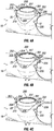
- the shaped charge 12 has a shaped charge retainer device 200 attached to the open end.
- the shaped charge retainer device 200 has a top body portion 201 with a substantially frusto-conical shape. It has a bottom body portion 209 with a substantially cylindrical shape. It has a first alignment tab 208 protruding tangentially from the surface of the bottom body portion 209. It has a second alignment tab 206 protruding tangentially from the surface of the bottom body portion 209. It has a first locking tab 203 protruding from the top body portion 210. It has a second locking tab 202 protruding from the top body portion 210.
- the first locking tab has a flat top 204.
- the second locking tab 202 has a second flat top 205.
- the shaped charge retainer device 200 can be fixed to the outer surface 29 of the shaped charge case 28 by snapping into place, set screws, adhesives, or some other well known means for affixing two object together.
- the shaped charge retainer device 200 may also simply sit on top of the shaped charge case 28, either loosely or rely on the friction from an interference fit.
- the shaped charge retainer device 200 has a first inner diameter 250 and a second inner diameter 251.
- the first inner diameter 250 is larger than the second inner diameter 251 in this example, creating a chamfer in conjunction with shoulder 252.
- a bridge 254 connects the first locking tab 203 to the top body portion 210.
- a bridge 253 can connect the second locking tab 202 to the top body portion 210, this allows the locking tab to flex as it is rotated into position.
- a shoulder 252 may limit the axial movement of the shaped charge 12 when the shaped charge retainer device 200 is locked into place within a charge tube.
- the shaped charge retainer device 200 may be composed of plastic, nylon, zytel, zinc, or other commonly used materials.
- the shaped charge retainer device 200 is shown from a perspective view without the shaped charge attached.
- the shaped charge retainer device 200 has a top body portion 201 with a substantially frusto-conical shape. It has a bottom body portion 209 with a substantially cylindrical shape. It has a first alignment tab 208 protruding tangentially from the surface of the bottom body portion 209. It has a second alignment tab 206 protruding tangentially from the surface of the bottom body portion 209. It has a first locking tab 203 protruding from the top body portion 210. It has a second locking tab 202 protruding from the top body portion 210.
- the first locking tab has a flat top 204.
- the second locking tab 202 has a second flat top 205. It has an inner surface 207.
- FIG. 4A This is a detail drawing of the retainer of a shaped charge 12 with the shaped charge retainer device 200 attached as it is inserted into a charge tube 18.
- the shaped charge retainer device 200 has a top body portion 201 with a substantially frusto-conical shape. It has a bottom body portion 209 with a substantially cylindrical shape. It has a first alignment tab 208 protruding tangentially from the surface of the bottom body portion 209. It has a second alignment tab 206 protruding tangentially from the surface of the bottom body portion 209.
- the shaped charge 12 is inserted into a charge tube 18 via charge hole 23.
- the charge tube 18 has cutouts 220 that are shaped such that the first alignment tab 208 and the second alignment tab 206 can fit through the cutouts 220.
- the installation procedure involves inserting the first alignment tab 208 and second alignment tab 206 through the keyed cutouts 220, then twisting the shaped charge retainer 200 a predetermined amount of twist angle until the first locking tab 203 and second locking tab 202 engage the keyed cutout 220.
- FIG. 4B this is a detail drawing of the retainer of a shaped charge 12 with the shaped charge retainer device 200 attached as it is inserted into a charge tube 18.
- the shaped charge retainer device 200 has a top body portion 201 with a substantially frusto-conical shape. It has a bottom body portion 209 with a substantially cylindrical shape. It has a first alignment tab 208 protruding tangentially from the surface of the bottom body portion 209. It has a second alignment tab 206 protruding tangentially from the surface of the bottom body portion 209. It has a first locking tab 203 protruding from the top body portion 210. It has a second locking tab 202 protruding from the top body portion 210.
- the first locking tab has a flat top 204.
- the second locking tab 202 has a second flat top 205. It has an inner surface 207.
- the shaped charge 12 is inserted into a charge tube 18 via charge hole 23.
- the charge tube 18 has cutouts 220 that are shaped such that the first alignment tab 208 and the second alignment tab 206 can fit through the cutouts 220. In this depiction the first alignment tab 208 and the second alignment tab 206 have passed through the cutouts 220.
- the shaped charge retainer device 200 can then be rotated in order to allow the first locking tab 203 and the second locking tab 202 to fit into cutouts 220.
- FIG. 4C this is a detail drawing of the retainer of a shaped charge 12 with the shaped charge retainer device 200 attached as it is inserted into a charge tube 18.
- the shaped charge retainer device 200 has a top body portion 201 with a substantially frusto-conical shape. It has a bottom body portion 209 with a substantially cylindrical shape. It has a first alignment tab 208 protruding tangentially from the surface of the bottom body portion 209. It has a second alignment tab 206 protruding tangentially from the surface of the bottom body portion 209. It has a first locking tab 203 protruding from the top body portion 210. It has a second locking tab 202 protruding from the top body portion 210.
- the first locking tab has a flat top 204.
- the second locking tab 202 has a second flat top 205. It has an inner surface 207.
- the shaped charge 12 is inserted into a charge tube 18 via charge hole 23.
- the charge tube 18 has cutouts 220 that are shaped such that the first alignment tab 208 and the second alignment tab 206 can fit through the cutouts 220. In this depiction the first alignment tab 208 and the second alignment tab 206 have passed through the cutouts 220.
- the shaped charge retainer device 200 has been rotated and the first locking tab 203 and the second locking tab 202 fits into cutouts 220.
- the first flat surface 204 and second flat surface 205 may be substantially flush with the outer surface of charge tube 18.
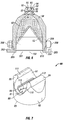
- This detonating cord retainer 70 has a base 71 with a through hole 74, a middle portion 72 with a through slot 73, and a upper portion 75 that is shaped as a truncated conical with a u-shaped channel 76 that is sized to snap onto a detonating cord.
- the detonating cord retainer 70 has a first axis 102 aligning the base 71, middle portion 72, and upper portion 75.
- the u-shaped channel 76 also has an axis 101 that is perpendicular to the axis 102.
- the base 71 snaps onto the end of a shaped charge with the edge of the u-shaped channel 76 adapted to snap over a lip.
- the detonating cord retainer 70 can be secured to the shaped charge, but still rotate to its desired orientation in order to snap to a detonating cord.
- the u-shaped channel 76 is designed to securely snap onto a detonating cord and restrict the movement of the detonating cord. In this embodiment the detonating cord could explode through the thin material 77 between the u-shaped channel 76 and the thru slot 73, whereby the explosion would travel down the thru hole 74 and into the back of a shaped charge.
- the thru slot 73 is perpendicular to axis 102.
- detonating cord retainer 70 has a base 71 that has a shoulder 121 capable of engaging the charge tube in such a way as to restrain the movement of the shaped charge along the axis 102, but allowing rotation about the axis 102.
- a thru hole or thru aperture could be located at 77 to facilitate explosive communication between the detonating cord and the shaped charge.
- An alternative to the u-shaped channel 76 is a c-shaped cutout in which the channel 76 is rotated 90 degrees such that the detonating cord is accepted from the side rather than the top as shown.
- the shoulder 78 allows the retainer 70 to snap onto the apex end 60 of a shaped charge, as shown in FIG. 6 .
- the shaped charge case 58 is attached to the detonating cord retainer 50.
- the shaped charge case 58 is machined with an apex end 60.
- the apex end 60 has a lip 59.
- the detonating cord retainer 50 snaps over the lip 59.
- the detonating cord retainer 50 could be threaded onto the shaped charge case 58, secured with adhesive, snapped around the full length of the shaped charge case 58, or formed integrally with the shaped charge case 58.
- the detonating cord retainer 50 could also be secured to the shaped charge case 58 using set screws, roll pins, or any other mechanical fasteners.
- the detonating cord 61 is snapped into the u-shaped cutout 56.
- the detonating cord retainer 50 can freely rotate when attached to the shaped charge case 58, however a set screw or other fastening device could be used to prevent rotation if desired.
- a set screw or other fastening device could be used to prevent rotation if desired.
- the detonating cord 61 detonates the explosion will puncture through the thin material 57 and enter thru hole 64 of the shaped charge case 58. The explosion will then interact with the explosive material 62 causing it to explode. The detonation of explosive material 62 will then transform liner 63 into a plasma jet capable of puncturing out of the perforating gun.
- the thin material 57 may be solid, it could also have a thru hole, perforations, a window or other aid that facilitates the explosion traveling from the detonating cord 61 to the explosive material 62.
- the u-shaped cutout 56 is depicted as having a gap between the two retaining ends 65, however the gap could be narrower such that the retaining ends 65 touch each other either before or after the detonating cord 61 is put into place.
- the detonating cord retainer 50 may be constructed of plastic using for instance an injection molding process or a rapid prototyping process.
- the detonating cord retainer 50 in this embodiment restricts the ability of the detonating cord 61 to move sideways, but it may allow the detonating cord 61 to move through the detonating cord retainer 50 and allows for rotation of the detonating cord 61 with respect to the shaped charge case 58.
- the shaped charge 12 has a shaped charge retainer device 200 attached to the open end.
- the shaped charge retainer device 200 has a top body portion 201 with a substantially frusto-conical shape. It has a bottom body portion 209 with a substantially cylindrical shape. Top body portion 201 and bottom body portion 209 share a common axis 103. It has a first alignment tab 208 protruding tangentially from the surface of the bottom body portion 209. It has a second alignment tab 206 protruding tangentially from the surface of the bottom body portion 209. It has a first locking tab 203 protruding from the top body portion 210.
- the shaped charge retainer device 200 can be fixed to the shaped charge case 28 by snapping into place, set screws, adhesives, or some other well known means for affixing two object together. The shaped charge retainer device 200 may also simply sit on top of the shaped charge case 28, either loosely or rely on the friction from an interference fit.
- FIG. 7 Another example embodiment of a detonating cord retainer 80 is shown in FIG. 7 . It is adapted to interface with the apex end of a shaped charge case.
- Detonating cord retainer 80 includes a base 82 having a bottom end 83 and a top end 88.
- a bore 81 extends into the base 82 from the bottom end 83.
- An aperture 89 in the top end 88 of the base 82 is adapted to allow detonation communication from the top end 88 of the base 82 into the bore 81.
- a first retention arm 86 having an inner face 87 extends substantially orthogonally from the top end 88 of the base 82.
- a second retention arm 84 has an inner face 110 extending substantially orthogonally from the top end 88 of the base 82.
- the inner face 87 of the first retention arm 86 is substantially parallel to and facing the inner face 110 of the second retention arm 84.
- the inner face 87 of the first retention arm 86 has a retention nub 111 distal from the base extending toward the second retention arm 84.
- the first retention arm 86 and second retention arm 84 are adapted to retain a detonating cord in proximity to the aperture 89.
- the inner face 110 of the second retention arm 84 has a retention nub 112 distal from the base extending toward the first retention arm 86.
- a circumferential ridge 113 is located in the bore 81 adapted to engage a corresponding groove in a shaped charge case.
- the circumferential ridge 113 may also be a circumferential groove adapted to engage a corresponding ridge in a shaped charge case.
- the aperture 89 extends from the top end 88 of the body 82 to the bore 81.
- the bore 81 may extend through a portion of the top end 88 of the body 82 to form the aperture 89.
- An example of a method of use may include installing a shaped charge retainer 200 onto a shaped charge 12, installing that combination into a charge tube 18, inserting a plurality of keys, in this case first alignment tab 208 and second alignment tab 206 into a plurality of key cutouts 220 located on the charge tube 18.
- the aligned shaped charge retainer 200 is then inserted until the keys, alignment tabs 206 and 208, are through the charge tube cutouts 220.
- the shaped charge retainer 200 is rotated or twisted about its axis after passing the plurality of keys through the plurality of corresponding keyways until snapping the a plurality of locking tabs, in this case locking tabs 202 and 203, into the plurality of cutouts 220.
Landscapes
- Engineering & Computer Science (AREA)
- Geology (AREA)
- Life Sciences & Earth Sciences (AREA)
- Mining & Mineral Resources (AREA)
- Environmental & Geological Engineering (AREA)
- Fluid Mechanics (AREA)
- Physics & Mathematics (AREA)
- General Life Sciences & Earth Sciences (AREA)
- Geochemistry & Mineralogy (AREA)
- General Engineering & Computer Science (AREA)
- Connector Housings Or Holding Contact Members (AREA)
- Manufacturing Of Electrical Connectors (AREA)
- Harvester Elements (AREA)
Claims (15)
- Eine Hohlladungshaltevorrichtung (200), aufweisend:einen unteren Ringabschnitt (209), welcher im Wesentlichen zylindrisch um eine Achse (103) ist und einen ersten Innendurchmesser aufweist,einen oberen Abschnitt (201), welcher im Wesentlichen zylindrisch um die Achse (103) ist, einen zweiten Innendurchmesser (251) aufweist, und an dem unteren Ringabschnitt (209) angebracht und davon axial versetzt ist,eine erste Nase (208), welche radial von dem unteren Ringabschnitt (209) aus vorsteht, undeinen ersten Verriegelungsvorsprung (203), welcher radial von dem oberen Abschnitt (201) aus vorsteht, oberhalb der ersten Nase (208) entlang der Achse (103) angeordnet ist, und um einen ersten Verdrehwinkel um die Achse von der ersten Nase (208) aus versetzt ist, wobei der erste Verriegelungsvorsprung (203) einen Brückenabschnitt (254, 253) und einen Vorsprungabschnitt aufweist, wobei der Brückenabschnitt (254, 253) den Vorsprungabschnitt mit dem oberen Abschnitt (201) verbindet und der Brückenabschnitt (254, 253) in seiner Abmessung parallel zur Achse (103) kürzer als der Vorsprungabschnitt ist, um es dem Verriegelungsvorsprung (203) zu erlauben, sich zu verbiegen, wenn er in Position gedreht wird.
- Die Haltevorrichtung nach Anspruch 1, ferner aufweisend eine zweite Nase (206), welche radial von dem unteren zylindrischen Ringabschnitt (209) aus vorsteht und axial um die Achse herum angeordnet ist, wobei die zweite Nase (206) optional axial um die Achse herum von der ersten Nase (208) aus um 180 Grad angeordnet ist.
- Die Haltevorrichtung nach Anspruch 1, ferner aufweisend einen zweiten Verriegelungsvorsprung (202), welcher radial von dem oberen Abschnitt (201) aus vorsteht und axial um die Achse herum angeordnet ist, wobei der zweite Verriegelungsvorsprung optional axial um die Achse herum von dem ersten Verriegelungsvorsprung aus um 180 Grad angeordnet ist.
- Die Haltevorrichtung nach Anspruch 1, ferner aufweisend, dass die Hohlladungshaltevorrichtung (200 aus Zytel gebildet ist.
- Die Haltevorrichtung nach Anspruch 1, ferner aufweisend, dass der Verriegelungsvorsprung eine bündige obere Fläche (204, 205) aufweist, welche dazu eingerichtet ist, bündig mit einem Perforationsladungsrohr (18) zu sein.
- Die Haltevorrichtung nach Anspruch 1, wobei der obere Abschnitt (201) kegelstumpfförmig ist.
- Die Haltevorrichtung nach Anspruch 1, ferner aufweisend eine zweite Nase und eine dritte Nase, welche von dem unteren zylindrischen Ringabschnitt aus vorstehen und axial um die Achse herum angeordnet sind, wobei die erste Nase, die zweite Nase und die dritte Nase optional axial um die Achse herum voneinander um 120 Grad angeordnet sind.
- Die Haltevorrichtung nach Anspruch 1, ferner aufweisend einen zweiten Verriegelungsvorsprung und einen dritten Verriegelungsvorsprung, welche radial von dem oberen Abschnitt aus vorstehen und axial um die Achse herum angeordnet sind, wobei der erste Verriegelungsvorsprung, der zweite Verriegelungsvorsprung und der dritte Verriegelungsvorsprung optional axial um die Achse herum voneinander um 120 Grad angeordnet sind.
- Verfahren zum Installieren von mindestens einer Hohlladung unter Verwendung einer Hohlladungshaltevorrichtung, welche mindestens die Merkmale von Ansprüchen 1 bis 3 und optional von irgendeinem der Ansprüche 4 bis 8 aufweist, wobei das Verfahren aufweist:Platzieren einer Hohlladungshaltevorrichtung (200) mit einer Mehrzahl von Nasen (208, 206) auf einem offenen Ende einer Hohlladung,Einsetzen der Hohlladung (12) mit der Hohlladungshaltevorrichtung (200) in einen Ladungsrohrausschnitt (220),Ausrichten der Hohlladungshaltevorrichtung (200) mit einer Mehrzahl von Aussparungen in dem Ladungsrohr (18),Führen der Mehrzahl von Nasen (208, 206) an der Hohlladungshaltevorrichtung (200) hindurch durch die Mehrzahl von Aussparungen an dem Ladungsrohrausschnitt (220),Drehen der Hohlladungshaltevorrichtung (200) nach dem Hindurchführen der Mehrzahl von Nasen (208, 206) durch die Mehrzahl von korrespondierenden Aussparungen,Einschnappen von einer Mehrzahl von an der Hohlladungshaltevorrichtung (200) angeordneten Verriegelungsvorsprüngen (202, 203) in die Mehrzahl von Aussparungen.
- Das Verfahren nach Anspruch 9, ferner aufweisend das Platzieren einer u-förmigen Sprengschnur-Haltevorrichtung (70) am Scheitelende (60) der Hohlladung (12).
- Das Verfahren nach Anspruch 9, ferner aufweisend das Anbringen einer Sprengschnur (61) an der Hohlladung (12).
- Das Verfahren nach Anspruch 9, wobei die mindestens eine Hohlladung (12) eine Mehrzahl von Ladungen, welche in einem einzelnen Ladungsrohr (18) installiert werden, darstellt.
- Das Verfahren nach Anspruch 9, ferner aufweisend das Installieren des Ladungsrohrs (18) in einer Perforationsschiessvorrichtung (10), wobei das Verfahren ferner optional das Verbringen der Perforationsschiessvorrichtung (10) zu einer vorbestimmten Bohrlochposition aufweist, und wobei das Verfahren ferner optional das Detonieren der mindestens einen Hohlladung (12) aufweist.
- Ein Hohlladung-Haltesystem, aufweisend:ein Hohlladungsgehäuse (28) mit einem Scheitelende (46) und einem Sprengstoffaus lassende,ein Ladungsrohr (18) mit einer Mittelachse, welches eine erste Mehrzahl von kreisförmigen Ausschnitten (31), welche dazu eingerichtet sind, mit dem Scheitelende (46) des Hohlladungsgehäuses zu koppeln, und eine zweite Mehrzahl von kreisförmigen Ausschnitten (220), welche um 180 Grad entgegengesetzt zu der ersten Mehrzahl von kreisförmigen Ausschnitten (31) um die Ladungsrohrachse herum angeordnet sind, aufweist,eine Sprengschnur (61),eine Hohlladungshaltevorrichtung (200) gemäß irgendeinem der Ansprüche 1 bis 8,wobei optional die Hohlladungshaltevorrichtung (200) sich um die Hohlladung um 360 Grad drehen kann.
- Das System nach Anspruch 14, wobei die Hohlladungshaltevorrichtung aus Kunststoff gebildet ist.
Applications Claiming Priority (2)
| Application Number | Priority Date | Filing Date | Title |
|---|---|---|---|
| US201562201868P | 2015-08-06 | 2015-08-06 | |
| PCT/US2016/045880 WO2017024266A1 (en) | 2015-08-06 | 2016-08-05 | Shaped charge retaining device |
Publications (3)
| Publication Number | Publication Date |
|---|---|
| EP3332087A1 EP3332087A1 (de) | 2018-06-13 |
| EP3332087A4 EP3332087A4 (de) | 2019-04-10 |
| EP3332087B1 true EP3332087B1 (de) | 2020-12-23 |
Family
ID=57944182
Family Applications (1)
| Application Number | Title | Priority Date | Filing Date |
|---|---|---|---|
| EP16833965.3A Not-in-force EP3332087B1 (de) | 2015-08-06 | 2016-08-05 | Hohlladungshaltevorrichtung |
Country Status (4)
| Country | Link |
|---|---|
| US (1) | US11199076B2 (de) |
| EP (1) | EP3332087B1 (de) |
| CA (1) | CA2993990C (de) |
| WO (1) | WO2017024266A1 (de) |
Families Citing this family (18)
| Publication number | Priority date | Publication date | Assignee | Title |
|---|---|---|---|---|
| WO2016168491A1 (en) * | 2015-04-14 | 2016-10-20 | Hunting Titan, Inc. | Detonating cord retaining device |
| US11661824B2 (en) | 2018-05-31 | 2023-05-30 | DynaEnergetics Europe GmbH | Autonomous perforating drone |
| US10458213B1 (en) | 2018-07-17 | 2019-10-29 | Dynaenergetics Gmbh & Co. Kg | Positioning device for shaped charges in a perforating gun module |
| US11078763B2 (en) | 2018-08-10 | 2021-08-03 | Gr Energy Services Management, Lp | Downhole perforating tool with integrated detonation assembly and method of using same |
| US11994008B2 (en) | 2018-08-10 | 2024-05-28 | Gr Energy Services Management, Lp | Loaded perforating gun with plunging charge assembly and method of using same |
| US10858919B2 (en) | 2018-08-10 | 2020-12-08 | Gr Energy Services Management, Lp | Quick-locking detonation assembly of a downhole perforating tool and method of using same |
| USD1019709S1 (en) | 2019-02-11 | 2024-03-26 | DynaEnergetics Europe GmbH | Charge holder |
| CN110345823B (zh) * | 2019-08-22 | 2024-04-05 | 长安大学 | 一种聚能管 |
| US11187512B1 (en) | 2019-08-29 | 2021-11-30 | The United States Of America As Represented By The Secretary Of The Navy | Apparatus for detonating munitions |
| US11480038B2 (en) | 2019-12-17 | 2022-10-25 | DynaEnergetics Europe GmbH | Modular perforating gun system |
| CN116670375A (zh) * | 2020-12-08 | 2023-08-29 | 狩猎巨人公司 | 单能量源的射弹射孔系统 |
| US11732556B2 (en) | 2021-03-03 | 2023-08-22 | DynaEnergetics Europe GmbH | Orienting perforation gun assembly |
| US11649703B2 (en) | 2021-05-14 | 2023-05-16 | Halliburton Energy Services, Inc. | Preferential fragmentation of charge case during perforating |
| US12000267B2 (en) | 2021-09-24 | 2024-06-04 | DynaEnergetics Europe GmbH | Communication and location system for an autonomous frack system |
| CN114293957A (zh) * | 2022-02-21 | 2022-04-08 | 黑龙江奥昆科技开发有限公司 | 一种定向阶梯式缝网压裂射孔装置 |
| WO2024145013A1 (en) * | 2022-12-28 | 2024-07-04 | Schlumberger Technology Corporation | Passively orientated gun for plug and abandonment applications |
| US20250327385A1 (en) * | 2024-04-19 | 2025-10-23 | Greenwell Engineering, Inc. | Addressable switch and orienting device adaptor for a perforating gun |
| WO2026019543A1 (en) * | 2024-07-15 | 2026-01-22 | C-2 Innovations, Inc. | Improved line charge |
Family Cites Families (14)
| Publication number | Priority date | Publication date | Assignee | Title |
|---|---|---|---|---|
| US3094930A (en) | 1960-05-18 | 1963-06-25 | Schlumberger Well Surv Corp | Expendable perforating apparatus |
| US3468386A (en) | 1967-09-05 | 1969-09-23 | Harold E Johnson | Formation perforator |
| US4817531A (en) * | 1987-10-05 | 1989-04-04 | Jet Research Center, Inc. | Capsule charge retaining device |
| US4832134A (en) * | 1987-12-07 | 1989-05-23 | Jet Research Center, Inc. | Shaped charge assembly with retaining clip |
| US4889183A (en) * | 1988-07-14 | 1989-12-26 | Halliburton Services | Method and apparatus for retaining shaped charges |
| US5862758A (en) * | 1993-01-15 | 1999-01-26 | Schlumberger Technology Corporation | Insert and twist method and apparatus for securing a shaped charge to a loading tube of a perforating gun |
| US5673760A (en) * | 1995-11-09 | 1997-10-07 | Schlumberger Technology Corporation | Perforating gun including a unique high shot density packing arrangement |
| US5829538A (en) * | 1997-03-10 | 1998-11-03 | Owen Oil Tools, Inc. | Full bore gun system and method |
| GB2350149B (en) * | 2000-04-19 | 2001-05-16 | Morgan Matroc Ltd | Twist-lock fixing |
| US6487973B1 (en) * | 2000-04-25 | 2002-12-03 | Halliburton Energy Services, Inc. | Method and apparatus for locking charges into a charge holder |
| US7752971B2 (en) * | 2008-07-17 | 2010-07-13 | Baker Hughes Incorporated | Adapter for shaped charge casing |
| WO2011005826A1 (en) * | 2009-07-09 | 2011-01-13 | James Reaux | Surface controlled subsurface safety valve assembly with primary and secondary valves |
| US20130019770A1 (en) * | 2011-07-22 | 2013-01-24 | Halliburton Energy Services, Inc. | Device for perforating a material comprising a tail-locking charge case |
| US9133695B2 (en) * | 2011-09-03 | 2015-09-15 | Baker Hughes Incorporated | Degradable shaped charge and perforating gun system |
-
2016
- 2016-08-05 WO PCT/US2016/045880 patent/WO2017024266A1/en not_active Ceased
- 2016-08-05 US US15/747,711 patent/US11199076B2/en not_active Expired - Fee Related
- 2016-08-05 EP EP16833965.3A patent/EP3332087B1/de not_active Not-in-force
- 2016-08-05 CA CA2993990A patent/CA2993990C/en not_active Expired - Fee Related
Non-Patent Citations (1)
| Title |
|---|
| None * |
Also Published As
| Publication number | Publication date |
|---|---|
| CA2993990C (en) | 2019-06-04 |
| WO2017024266A1 (en) | 2017-02-09 |
| EP3332087A1 (de) | 2018-06-13 |
| CA2993990A1 (en) | 2017-02-09 |
| EP3332087A4 (de) | 2019-04-10 |
| US11199076B2 (en) | 2021-12-14 |
| US20180216445A1 (en) | 2018-08-02 |
Similar Documents
| Publication | Publication Date | Title |
|---|---|---|
| EP3332087B1 (de) | Hohlladungshaltevorrichtung | |
| EP3108093B1 (de) | Hohlladungsrückhaltesystem | |
| US20200370399A1 (en) | Detonating Cord Retaining Device | |
| EP3108097B1 (de) | Einteiliges zinkverbindungssystem | |
| EP3108092B1 (de) | Ausrichtungssystem für eine perforationspistole | |
| EP3278052B1 (de) | Einrast-rückhaltevorrichtung für auskleidung | |
| US20230009723A1 (en) | Shaped Charge Retainer System | |
| WO2018191668A1 (en) | Crimped attachment of end fitting to charge tube |
Legal Events
| Date | Code | Title | Description |
|---|---|---|---|
| STAA | Information on the status of an ep patent application or granted ep patent |
Free format text: STATUS: THE INTERNATIONAL PUBLICATION HAS BEEN MADE |
|
| PUAI | Public reference made under article 153(3) epc to a published international application that has entered the european phase |
Free format text: ORIGINAL CODE: 0009012 |
|
| STAA | Information on the status of an ep patent application or granted ep patent |
Free format text: STATUS: REQUEST FOR EXAMINATION WAS MADE |
|
| 17P | Request for examination filed |
Effective date: 20180216 |
|
| AK | Designated contracting states |
Kind code of ref document: A1 Designated state(s): AL AT BE BG CH CY CZ DE DK EE ES FI FR GB GR HR HU IE IS IT LI LT LU LV MC MK MT NL NO PL PT RO RS SE SI SK SM TR |
|
| AX | Request for extension of the european patent |
Extension state: BA ME |
|
| DAV | Request for validation of the european patent (deleted) | ||
| DAX | Request for extension of the european patent (deleted) | ||
| A4 | Supplementary search report drawn up and despatched |
Effective date: 20190313 |
|
| RIC1 | Information provided on ipc code assigned before grant |
Ipc: E21B 43/119 20060101ALI20190306BHEP Ipc: E21B 43/116 20060101ALI20190306BHEP Ipc: E21B 43/117 20060101AFI20190306BHEP Ipc: F42B 3/08 20060101ALI20190306BHEP |
|
| GRAP | Despatch of communication of intention to grant a patent |
Free format text: ORIGINAL CODE: EPIDOSNIGR1 |
|
| STAA | Information on the status of an ep patent application or granted ep patent |
Free format text: STATUS: GRANT OF PATENT IS INTENDED |
|
| INTG | Intention to grant announced |
Effective date: 20200720 |
|
| GRAS | Grant fee paid |
Free format text: ORIGINAL CODE: EPIDOSNIGR3 |
|
| GRAA | (expected) grant |
Free format text: ORIGINAL CODE: 0009210 |
|
| STAA | Information on the status of an ep patent application or granted ep patent |
Free format text: STATUS: THE PATENT HAS BEEN GRANTED |
|
| AK | Designated contracting states |
Kind code of ref document: B1 Designated state(s): AL AT BE BG CH CY CZ DE DK EE ES FI FR GB GR HR HU IE IS IT LI LT LU LV MC MK MT NL NO PL PT RO RS SE SI SK SM TR |
|
| REG | Reference to a national code |
Ref country code: GB Ref legal event code: FG4D |
|
| REG | Reference to a national code |
Ref country code: DE Ref legal event code: R096 Ref document number: 602016050349 Country of ref document: DE |
|
| REG | Reference to a national code |
Ref country code: AT Ref legal event code: REF Ref document number: 1347898 Country of ref document: AT Kind code of ref document: T Effective date: 20210115 |
|
| REG | Reference to a national code |
Ref country code: IE Ref legal event code: FG4D |
|
| REG | Reference to a national code |
Ref country code: NL Ref legal event code: FP |
|
| PG25 | Lapsed in a contracting state [announced via postgrant information from national office to epo] |
Ref country code: GR Free format text: LAPSE BECAUSE OF FAILURE TO SUBMIT A TRANSLATION OF THE DESCRIPTION OR TO PAY THE FEE WITHIN THE PRESCRIBED TIME-LIMIT Effective date: 20210324 Ref country code: FI Free format text: LAPSE BECAUSE OF FAILURE TO SUBMIT A TRANSLATION OF THE DESCRIPTION OR TO PAY THE FEE WITHIN THE PRESCRIBED TIME-LIMIT Effective date: 20201223 Ref country code: RS Free format text: LAPSE BECAUSE OF FAILURE TO SUBMIT A TRANSLATION OF THE DESCRIPTION OR TO PAY THE FEE WITHIN THE PRESCRIBED TIME-LIMIT Effective date: 20201223 |
|
| REG | Reference to a national code |
Ref country code: AT Ref legal event code: MK05 Ref document number: 1347898 Country of ref document: AT Kind code of ref document: T Effective date: 20201223 |
|
| PG25 | Lapsed in a contracting state [announced via postgrant information from national office to epo] |
Ref country code: BG Free format text: LAPSE BECAUSE OF FAILURE TO SUBMIT A TRANSLATION OF THE DESCRIPTION OR TO PAY THE FEE WITHIN THE PRESCRIBED TIME-LIMIT Effective date: 20210323 Ref country code: LV Free format text: LAPSE BECAUSE OF FAILURE TO SUBMIT A TRANSLATION OF THE DESCRIPTION OR TO PAY THE FEE WITHIN THE PRESCRIBED TIME-LIMIT Effective date: 20201223 Ref country code: SE Free format text: LAPSE BECAUSE OF FAILURE TO SUBMIT A TRANSLATION OF THE DESCRIPTION OR TO PAY THE FEE WITHIN THE PRESCRIBED TIME-LIMIT Effective date: 20201223 |
|
| REG | Reference to a national code |
Ref country code: NO Ref legal event code: T2 Effective date: 20201223 |
|
| PG25 | Lapsed in a contracting state [announced via postgrant information from national office to epo] |
Ref country code: HR Free format text: LAPSE BECAUSE OF FAILURE TO SUBMIT A TRANSLATION OF THE DESCRIPTION OR TO PAY THE FEE WITHIN THE PRESCRIBED TIME-LIMIT Effective date: 20201223 |
|
| REG | Reference to a national code |
Ref country code: LT Ref legal event code: MG9D |
|
| PG25 | Lapsed in a contracting state [announced via postgrant information from national office to epo] |
Ref country code: SK Free format text: LAPSE BECAUSE OF FAILURE TO SUBMIT A TRANSLATION OF THE DESCRIPTION OR TO PAY THE FEE WITHIN THE PRESCRIBED TIME-LIMIT Effective date: 20201223 Ref country code: RO Free format text: LAPSE BECAUSE OF FAILURE TO SUBMIT A TRANSLATION OF THE DESCRIPTION OR TO PAY THE FEE WITHIN THE PRESCRIBED TIME-LIMIT Effective date: 20201223 Ref country code: PT Free format text: LAPSE BECAUSE OF FAILURE TO SUBMIT A TRANSLATION OF THE DESCRIPTION OR TO PAY THE FEE WITHIN THE PRESCRIBED TIME-LIMIT Effective date: 20210423 Ref country code: EE Free format text: LAPSE BECAUSE OF FAILURE TO SUBMIT A TRANSLATION OF THE DESCRIPTION OR TO PAY THE FEE WITHIN THE PRESCRIBED TIME-LIMIT Effective date: 20201223 Ref country code: CZ Free format text: LAPSE BECAUSE OF FAILURE TO SUBMIT A TRANSLATION OF THE DESCRIPTION OR TO PAY THE FEE WITHIN THE PRESCRIBED TIME-LIMIT Effective date: 20201223 Ref country code: SM Free format text: LAPSE BECAUSE OF FAILURE TO SUBMIT A TRANSLATION OF THE DESCRIPTION OR TO PAY THE FEE WITHIN THE PRESCRIBED TIME-LIMIT Effective date: 20201223 Ref country code: LT Free format text: LAPSE BECAUSE OF FAILURE TO SUBMIT A TRANSLATION OF THE DESCRIPTION OR TO PAY THE FEE WITHIN THE PRESCRIBED TIME-LIMIT Effective date: 20201223 |
|
| PG25 | Lapsed in a contracting state [announced via postgrant information from national office to epo] |
Ref country code: PL Free format text: LAPSE BECAUSE OF FAILURE TO SUBMIT A TRANSLATION OF THE DESCRIPTION OR TO PAY THE FEE WITHIN THE PRESCRIBED TIME-LIMIT Effective date: 20201223 Ref country code: AT Free format text: LAPSE BECAUSE OF FAILURE TO SUBMIT A TRANSLATION OF THE DESCRIPTION OR TO PAY THE FEE WITHIN THE PRESCRIBED TIME-LIMIT Effective date: 20201223 |
|
| REG | Reference to a national code |
Ref country code: DE Ref legal event code: R097 Ref document number: 602016050349 Country of ref document: DE |
|
| PG25 | Lapsed in a contracting state [announced via postgrant information from national office to epo] |
Ref country code: IS Free format text: LAPSE BECAUSE OF FAILURE TO SUBMIT A TRANSLATION OF THE DESCRIPTION OR TO PAY THE FEE WITHIN THE PRESCRIBED TIME-LIMIT Effective date: 20210423 |
|
| PG25 | Lapsed in a contracting state [announced via postgrant information from national office to epo] |
Ref country code: IT Free format text: LAPSE BECAUSE OF FAILURE TO SUBMIT A TRANSLATION OF THE DESCRIPTION OR TO PAY THE FEE WITHIN THE PRESCRIBED TIME-LIMIT Effective date: 20201223 Ref country code: AL Free format text: LAPSE BECAUSE OF FAILURE TO SUBMIT A TRANSLATION OF THE DESCRIPTION OR TO PAY THE FEE WITHIN THE PRESCRIBED TIME-LIMIT Effective date: 20201223 |
|
| PLBE | No opposition filed within time limit |
Free format text: ORIGINAL CODE: 0009261 |
|
| STAA | Information on the status of an ep patent application or granted ep patent |
Free format text: STATUS: NO OPPOSITION FILED WITHIN TIME LIMIT |
|
| PG25 | Lapsed in a contracting state [announced via postgrant information from national office to epo] |
Ref country code: DK Free format text: LAPSE BECAUSE OF FAILURE TO SUBMIT A TRANSLATION OF THE DESCRIPTION OR TO PAY THE FEE WITHIN THE PRESCRIBED TIME-LIMIT Effective date: 20201223 |
|
| 26N | No opposition filed |
Effective date: 20210924 |
|
| PG25 | Lapsed in a contracting state [announced via postgrant information from national office to epo] |
Ref country code: ES Free format text: LAPSE BECAUSE OF FAILURE TO SUBMIT A TRANSLATION OF THE DESCRIPTION OR TO PAY THE FEE WITHIN THE PRESCRIBED TIME-LIMIT Effective date: 20201223 |
|
| PG25 | Lapsed in a contracting state [announced via postgrant information from national office to epo] |
Ref country code: SI Free format text: LAPSE BECAUSE OF FAILURE TO SUBMIT A TRANSLATION OF THE DESCRIPTION OR TO PAY THE FEE WITHIN THE PRESCRIBED TIME-LIMIT Effective date: 20201223 |
|
| REG | Reference to a national code |
Ref country code: DE Ref legal event code: R119 Ref document number: 602016050349 Country of ref document: DE |
|
| REG | Reference to a national code |
Ref country code: NO Ref legal event code: MMEP |
|
| REG | Reference to a national code |
Ref country code: CH Ref legal event code: PL |
|
| PG25 | Lapsed in a contracting state [announced via postgrant information from national office to epo] |
Ref country code: MC Free format text: LAPSE BECAUSE OF FAILURE TO SUBMIT A TRANSLATION OF THE DESCRIPTION OR TO PAY THE FEE WITHIN THE PRESCRIBED TIME-LIMIT Effective date: 20201223 |
|
| REG | Reference to a national code |
Ref country code: NL Ref legal event code: MM Effective date: 20210901 |
|
| REG | Reference to a national code |
Ref country code: BE Ref legal event code: MM Effective date: 20210831 |
|
| GBPC | Gb: european patent ceased through non-payment of renewal fee |
Effective date: 20210805 |
|
| PG25 | Lapsed in a contracting state [announced via postgrant information from national office to epo] |
Ref country code: LI Free format text: LAPSE BECAUSE OF NON-PAYMENT OF DUE FEES Effective date: 20210831 Ref country code: CH Free format text: LAPSE BECAUSE OF NON-PAYMENT OF DUE FEES Effective date: 20210831 |
|
| PG25 | Lapsed in a contracting state [announced via postgrant information from national office to epo] |
Ref country code: IS Free format text: LAPSE BECAUSE OF FAILURE TO SUBMIT A TRANSLATION OF THE DESCRIPTION OR TO PAY THE FEE WITHIN THE PRESCRIBED TIME-LIMIT Effective date: 20210423 Ref country code: NO Free format text: LAPSE BECAUSE OF NON-PAYMENT OF DUE FEES Effective date: 20210831 Ref country code: LU Free format text: LAPSE BECAUSE OF NON-PAYMENT OF DUE FEES Effective date: 20210805 |
|
| PG25 | Lapsed in a contracting state [announced via postgrant information from national office to epo] |
Ref country code: NL Free format text: LAPSE BECAUSE OF NON-PAYMENT OF DUE FEES Effective date: 20210901 |
|
| PG25 | Lapsed in a contracting state [announced via postgrant information from national office to epo] |
Ref country code: IE Free format text: LAPSE BECAUSE OF NON-PAYMENT OF DUE FEES Effective date: 20210805 Ref country code: GB Free format text: LAPSE BECAUSE OF NON-PAYMENT OF DUE FEES Effective date: 20210805 Ref country code: FR Free format text: LAPSE BECAUSE OF NON-PAYMENT OF DUE FEES Effective date: 20210831 Ref country code: DE Free format text: LAPSE BECAUSE OF NON-PAYMENT OF DUE FEES Effective date: 20220301 Ref country code: BE Free format text: LAPSE BECAUSE OF NON-PAYMENT OF DUE FEES Effective date: 20210831 |
|
| PG25 | Lapsed in a contracting state [announced via postgrant information from national office to epo] |
Ref country code: HU Free format text: LAPSE BECAUSE OF FAILURE TO SUBMIT A TRANSLATION OF THE DESCRIPTION OR TO PAY THE FEE WITHIN THE PRESCRIBED TIME-LIMIT; INVALID AB INITIO Effective date: 20160805 |
|
| PG25 | Lapsed in a contracting state [announced via postgrant information from national office to epo] |
Ref country code: CY Free format text: LAPSE BECAUSE OF FAILURE TO SUBMIT A TRANSLATION OF THE DESCRIPTION OR TO PAY THE FEE WITHIN THE PRESCRIBED TIME-LIMIT Effective date: 20201223 |
|
| PG25 | Lapsed in a contracting state [announced via postgrant information from national office to epo] |
Ref country code: MK Free format text: LAPSE BECAUSE OF FAILURE TO SUBMIT A TRANSLATION OF THE DESCRIPTION OR TO PAY THE FEE WITHIN THE PRESCRIBED TIME-LIMIT Effective date: 20201223 |
|
| PG25 | Lapsed in a contracting state [announced via postgrant information from national office to epo] |
Ref country code: MT Free format text: LAPSE BECAUSE OF FAILURE TO SUBMIT A TRANSLATION OF THE DESCRIPTION OR TO PAY THE FEE WITHIN THE PRESCRIBED TIME-LIMIT Effective date: 20201223 |
|
| PG25 | Lapsed in a contracting state [announced via postgrant information from national office to epo] |
Ref country code: TR Free format text: LAPSE BECAUSE OF FAILURE TO SUBMIT A TRANSLATION OF THE DESCRIPTION OR TO PAY THE FEE WITHIN THE PRESCRIBED TIME-LIMIT Effective date: 20201223 |