EP3332081B1 - Diverter für den bohrbetrieb - Google Patents
Diverter für den bohrbetrieb Download PDFInfo
- Publication number
- EP3332081B1 EP3332081B1 EP16833448.0A EP16833448A EP3332081B1 EP 3332081 B1 EP3332081 B1 EP 3332081B1 EP 16833448 A EP16833448 A EP 16833448A EP 3332081 B1 EP3332081 B1 EP 3332081B1
- Authority
- EP
- European Patent Office
- Prior art keywords
- diverter
- packer
- assembly
- upper packer
- sleeve
- Prior art date
- Legal status (The legal status is an assumption and is not a legal conclusion. Google has not performed a legal analysis and makes no representation as to the accuracy of the status listed.)
- Active
Links
Images





Classifications
-
- E—FIXED CONSTRUCTIONS
- E21—EARTH OR ROCK DRILLING; MINING
- E21B—EARTH OR ROCK DRILLING; OBTAINING OIL, GAS, WATER, SOLUBLE OR MELTABLE MATERIALS OR A SLURRY OF MINERALS FROM WELLS
- E21B33/00—Sealing or packing boreholes or wells
- E21B33/10—Sealing or packing boreholes or wells in the borehole
- E21B33/12—Packers; Plugs
-
- E—FIXED CONSTRUCTIONS
- E21—EARTH OR ROCK DRILLING; MINING
- E21B—EARTH OR ROCK DRILLING; OBTAINING OIL, GAS, WATER, SOLUBLE OR MELTABLE MATERIALS OR A SLURRY OF MINERALS FROM WELLS
- E21B33/00—Sealing or packing boreholes or wells
- E21B33/02—Surface sealing or packing
- E21B33/03—Well heads; Setting-up thereof
Definitions
- the present disclosure relates to diverters for drilling operations.
- a diverter While drilling a wellbore, a diverter may be positioned to divert any high pressure fluid resulting from, for example, a blowout, away from the drilling floor.
- a diverter may couple to an upper end of a casing or a riser and be positioned about the drill string as the wellbore is drilled.
- the diverter is positioned beneath the drill floor or rotary table and includes one or more outlets that may be coupled to exhaust conduits away from the drill floor.
- US4971148 A discloses several embodiments of a flow diverter.
- US5178215 A discloses a rotary blowout preventer having a rotary housing rotably mounted within an outer housing.
- WO84/02374 A1 discloses a flow diverter apparatus having a housing and a piston and annular packer disposed therein.
- a diverter assembly (100) comprising:
- a diverter assembly includes a diverter body assembly.
- the diverter body assembly includes a diverter body, the diverter body fluidly coupled to the annulus of a wellbore via a casing or riser, and the diverter body including one or more diverter outlet ports fluidly coupled to the annulus of the wellbore.
- the diverter body assembly also includes an upper packer assembly.
- the upper packer assembly includes a packer sleeve, the packer sleeve mechanically coupled to the diverter body.
- the packer sleeve includes one or more breach lock slots.
- the upper packer assembly also includes an upper packer body having one or more packer breach lock tabs engaged with the breach lock slots of the packer sleeve.
- the diverter assembly also includes a diverter support housing, the diverter support housing coupled to the diverter body assembly.
- the present disclosure also provides for a method.
- the method includes providing a diverter body assembly including a diverter body, the diverter body fluidly coupled to the annulus of a wellbore via a casing or riser, and the diverter body including one or more diverter outlet ports fluidly coupled to the annulus of the wellbore.
- the method also includes coupling a packer sleeve to the diverter body, and inserting an upper packer body into the packer sleeve such that one or more packer breach lock tabs of the upper packer body engage one or more corresponding breach lock slots of the packer sleeve.
- the method additionally includes rotating the upper packer body to a closed position such that the breach lock slots retain the upper packer body to the packer sleeve and sealing, with the upper packer body, between the diverter body and a drill string passing therethrough.
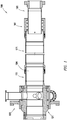
- FIG. 1 depicts a cross section of diverter assembly 100 consistent with at least one aspect of the present disclosure.
- diverter assembly 100 may include diverter support housing 101.
- Diverter support housing 101 may be mechanically coupled to a drill floor (not shown) or other component of a drilling rig by, for example and without limitation, one or more structural beams underneath and supporting the drill floor.
- Diverter support housing 101 may be mechanically coupled to diverter body assembly 121.
- Diverter assembly 100 further includes diverter lower assembly 151, spacer spool pipe 171 and overshot housing 181.
- Diverter body assembly 121 may be mechanically coupled to diverter lower assembly 151, which may be mechanically coupled to spacer spool pipe 171.
- Spacer spool pipe 171 may be mechanically coupled to overshot housing 181.
- Diverter body assembly 121, diverter lower assembly 151, spacer spool pipe 171, and overshot housing 181 may each be generally tubular and may form diverter assembly bore 104 therethrough.
- a drill string (not shown) may extend through diverter assembly bore 104.
- Overshot housing 181 may fit around a tubular such as a riser or a portion of casing such that diverter assembly bore 104 is coupled to the annulus of the wellbore via the riser or portion of casing.
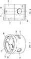
- diverter support housing 101 may include housing cylinder 102. Housing cylinder 102 may be coupled to base plate 103 as shown in FIG. 2 . Base plate 103 mechanically couples diverter support housing 101 to the drilling rig.
- one or more outlet pipes may be fluidly connected to diverter assembly bore 104.
- outlet pipes 105 may be formed at least partially in diverter support housing 101. During operation, one or more outlet pipes 105 may conduct fluid from diverter assembly bore 104, which is fluidly connected to the interior of diverter assembly 100 as discussed herein below.
- outlet pipes 105 may include couplers adapted to couple to exhaust conduits, allowing fluids to be routed to locations away from the drilling rig.
- the couplers may be flange couplings 107 as shown in FIG. 2 , though one having ordinary skill in the art with the benefit of this disclosure will understand that any pipe coupling may be used.
- Outlet pipes 105 (shown removed in FIGS. 3, 4 ) may couple to outlet ports 109 formed in housing cylinder 102.
- inlet ports 111 may be fluidly coupled to inlet pipes 113 to, for example, allow fluid to be introduced into housing cylinder 102.
- housing cylinder 102 may include housing breach lock slots 115.
- Housing breach lock slots 115 may, as understood in the art, allow one or more corresponding breach lock tabs 123 ( FIG. 5 ) from diverter body assembly 121 to axially enter thereinto and, upon rotation of diverter body assembly 121, axially lock diverter body assembly 121 to diverter support housing 101.
- housing breach lock slots 115 may include rotation stop 117 to retard further rotation of diverter body assembly 121 when in a locked position.
- Rotation stop 117 may in some aspects of the present disclosure retard rotation of diverter body assembly 121 in both rotational directions.
- diverter body assembly 121 may include diverter body 125.
- Diverter body 125 may include one or more diverter outlet ports 127, corresponding with outlet ports 109 of diverter support housing 101 thereby fluidly coupling diverter outlet ports 127 to outlet pipes 105 and the annulus of a wellbore.
- one or more seals 129 may be positioned between diverter body 125 and housing cylinder 102 to, for example and without limitation, provide a fluid seal between diverter outlet ports 127 and outlet ports 109.
- diverter body 125 may be fluidly coupled to the annulus of a wellbore via a casing or riser.
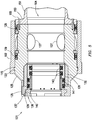
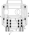
- diverter body assembly 121 may include upper packer assembly 131.
- Upper packer assembly 131 may form a fluid seal between diverter body 125 and a drill string (not shown) passing therethrough.
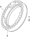
- Upper packer assembly 131 may include packer sleeve 132. Packer sleeve 132 may fit within packer recess 133 (shown in FIG. 6 ) within diverter body 125. Packer sleeve 132 may, in some aspects of the present disclosure, be coupled to diverter body 125 by, for example and without limitation, threaded fasteners such as bolts 137.
- Upper packer assembly 131 may include upper packer body 136 adapted to fit within packer sleeve 132.
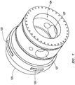
- Upper packer body may be annular. In some aspects of the present disclosure, upper packer body 136 may be inserted into or removed from packer sleeve 132 in an axial direction. In some aspects of the present disclosure, upper packer body 136 may be coupled to packer sleeve 132 and thus to diverter body 125 by upper retainer 135. In some aspects of the present disclosure, upper retainer 135 may include one or more breach lock slots 139 (shown in detail in FIG.
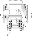
- upper packer assembly 131 may include two outer seals 141 coupled to upper packer body 136. Outer seals 141 may provide a fluid seal between upper packer assembly 131 and diverter body 125. In some aspects of the present disclosure, upper packer assembly 131 may include two inner seals 143 coupled to upper packer body 136. Inner seals 143 may provide a fluid seal between upper packer assembly 131 and a drill string (not shown) during a drilling operation. In some aspects of the present disclosure, outer seals 141 and inner seals 143 may be fluid actuated to extend and seal between the respective members.
- outer seals 141 and inner seals 143 may be, for example and without limitation, inflatable seals. In some aspects of the present disclosure, outer seals 141 and inner seals 143 may be inflated simultaneously or may be selectively inflated independently. In some aspects of the present disclosure, outer seals 141 and inner seals 143 may be inflated by one or more ports. In some aspects of the present disclosure, inner seals 143 may provide a fluid seal against multiple diameters or pipe sizes of a drill string. One having ordinary skill in the art with the benefit of this disclosure will understand that any number of outer seals 141 and inner seals 143 may be utilized. For example, in some aspects of the present disclosure, as depicted in FIG.
- upper packer assembly 131' may include three outer seals 141' and three inner seals 143'.
- outer seals 141' may be positioned as part of upper packer assembly 131'.
- outer seals 141" may be positioned as part of packer sleeve 132' positioned within diverter body 125 as previously discussed. In such an aspect of the present disclosure, outer seals 141" may seal against upper packer assembly 131".
- upper packer body 136 may be removed from the rest of diverter body assembly 121.
- upper packer body 136 may be rotated such that breach lock tabs 140 are aligned with breach lock slots 139 in an unlocked position, allowing upper packer body 136 to be axially removed from diverter body assembly 121.
- Replacement may similarly be accomplished by axially inserting upper packer body 136 into diverter body assembly 121 and rotating upper packer body 136 until breach lock tabs 140 are in a locked position within breach lock slots 139.
- diverter lower assembly 151 may couple to the lower end of diverter body 125.
- diverter lower assembly 151 may couple to diverter body 125 by a breach-lock assembly as described herein.
- diverter lower assembly 151 may include mounting flange 153 to mechanically couple diverter lower assembly 151 to the lower end of diverter body 125 by, for example and without limitation, threaded fasteners such as bolts 155.
- Diverter lower assembly 151 may be a tubular member.
- diverter lower assembly 151 may include a breach lock assembly including lock ring retainer 157.
- Lock ring retainer 157 may be a generally annular protrusion from the exterior surface of diverter lower assembly 151. Lock ring retainer 157 may, for example, retain lock ring 161 to diverter lower assembly 151. As depicted in FIG. 10 , lock ring 161 may include retaining flange 163 adapted to contact lock ring retainer 157 and prevent lock ring 161 from sliding off the end of diverter lower assembly 151. Lock ring 161 may further include breach lock slots 165 to couple to spacer spool pipe 171 and between spacer spool pipe 171 and overshot housing 181 as discussed herein.
- diverter lower assembly 151 may couple to spacer spool pipe 171 as depicted in FIG. 9 .
- spacer spool pipe 171 may include upper coupler 173.
- upper coupler 173 may include one or more breach lock tabs 175 adapted to engage with breach lock slots 165 of lock ring 161.
- spacer spool pipe 171 may be coupled to diverter lower assembly 151 by axially engaging the two members and inserting breach lock tabs 175 into breach lock slots 165 of lock ring 161. Lock ring 161 may then be rotated such that breach lock slots 165 engage breach lock tabs 175, retaining diverter lower assembly 151 to spacer spool pipe 171.
- spacer spool pipe 171 may include lock ring retainer 177.
- Lock ring retainer 177 may be a generally annular protrusion from the exterior surface of spacer spool pipe 171.
- Lock ring retainer 177 may, for example, retain lock ring 201 to spacer spool pipe 171 as discussed above with respect to diverter lower assembly.
- Lock ring 201 may include retaining flange 203 adapted to contact lock ring retainer 177 and prevent lock ring 201 from sliding off the end of spacer spool pipe 171.
- spacer spool pipe 171 may couple to overshot housing 181.
- overshot housing 181 may include upper coupler 183.
- upper coupler 183 may include one or more overshot breach lock tabs 185 adapted to engage with overshot breach lock slots 165 of overshot lock ring 161.
- overshot housing 181 may be coupled to spacer spool pipe 171 by axially engaging the two members and inserting overshot breach lock tabs 185 into overshot breach lock slots 165 of overshot lock ring 161. Overshot lock ring 161 may then be rotated such that overshot breach lock slots 165 engage overshot breach lock tabs 185, retaining spacer spool pipe 171 to overshot housing 181.
- overshot housing 181 may be adapted to slip over a casing portion or riser, depicted as mandrel 191.
- Overshot housing 181 may be tubular and may include a plurality of seals 187 positioned within annular grooves 189 formed on the inner surface thereof. Seals 187 may serve to provide a fluid seal between mandrel 191 and diverter assembly bore 104. In some aspects of the present disclosure, two or three seals 187 may be utilized.
- mandrel 191 may include lower coupler 197. Lower coupler 197 may allow mandrel 191 to couple to additional drilling components. In some aspects of the present disclosure, lower coupler 197 may include coupler flange 199.
Landscapes
- Engineering & Computer Science (AREA)
- Life Sciences & Earth Sciences (AREA)
- Geology (AREA)
- Mining & Mineral Resources (AREA)
- Physics & Mathematics (AREA)
- Environmental & Geological Engineering (AREA)
- Fluid Mechanics (AREA)
- General Life Sciences & Earth Sciences (AREA)
- Geochemistry & Mineralogy (AREA)
- Earth Drilling (AREA)
- Mechanical Engineering (AREA)
Claims (2)
- Diverteranordnung (100), umfassend:eine Diverterkörperanordnung (121), die einen Diverterkörper (125) beinhaltet, wobei der Diverterkörper (125) fluidisch mit dem Ringraum eines Bohrlochs über eine Verrohrung oder ein Steigrohr verbunden ist, wobei der Diverterkörper (125) einen oder mehrere Diverterauslassanschlüsse (127), die fluidisch mit dem Ringraum des Bohrlochs verbunden sind, beinhaltet, undeine obere Packeranordnung (131), die dafür ausgelegt ist, eine Dichtung zwischen dem Diverterkörper (125) und einem hindurch verlaufenden Bohrstrang zu bilden, wobei die obere Packeranordnung (131) beinhaltet:eine Packermanschette (132), wobei die Packermanschette (132) mechanisch mit dem Diverterkörper (125) verbunden ist, wobei die Packermanschette (132) eine Achse aufweist, wobei die Packermanschette (132) eine Bruchsicherung (139) beinhaltet; und einen oberen Packerkörper (136), wobei der obere Packerkörper (136) ausgelegt ist zum Einführen in die oder Entfernen aus der Packermanschette (132) entlang der Packermanschettenachse, mit einer oder mehreren Packer-Bruchsicherungsarretierungen (140), die ausgelegt sind zum Ineingriffnehmen der Bruchsicherungen (139) der Packermanschette (132), um dem oberen Packerkörper (136) zu erlauben, sich damit zu verbinden, wenn der obere Packerkörper (136) in eine geschlossene Position aus der offenen Position gedreht wird, die zum Einführen des oberen Packerkörpers (136) in die Packermanschette (132) benutzt wird;ein Diverter-Traggehäuse (101), wobei das Diverter-Traggehäuse (101) aufweist eine Grundplatte (103), wobei die Grundplatte (103) ausgelegt ist zum Verbinden mit einer Bohrvorrichtung; undeinen Gehäusezylinder (102), der mit einer Grundplatte (103) verbunden ist und mit dem Diverterkörper (125) verbunden ist;wobei die obere Packeranordnung (131) ferner mindestens zwei aufblasbare äußere Dichtungen (141) umfasst, wobei die aufblasbaren äußeren Dichtungen (141) auf einer Außenfläche des oberen Packerkörpers (136) positioniert sind, sodass die aufblasbaren äußeren Dichtungen (141) eine Fluiddichtung zwischen dem oberen Packerkörper (136) und dem Diverterkörper (125) oder der Packermanschette (132) bilden, wobei die aufblasbaren äußeren Dichtungen (141) dafür ausgelegt sind, gleichzeitig oder selektiv unabhängig aufgeblasen zu werden; unddadurch gekennzeichnet, dass die obere Packeranordnung (131) ferner mindestens zwei aufblasbare innere Dichtungen (143) umfasst, wobei die aufblasbaren inneren Dichtungen (143) auf einer Innenfläche des oberen Packerkörpers (136) positioniert sind, sodass die aufblasbaren inneren Dichtungen (143) eine Fluiddichtung zwischen dem oberen Packerkörper (136) und multiplen Durchmessern oder Rohrgrößen eines Bohrstrangs bilden, wobei die aufblasbaren inneren Dichtungen (143) dafür ausgelegt sind, gleichzeitig oder selektiv unabhängig aufgeblasen zu werden.
- Verfahren, umfassend:Verbinden einer Grundplatte (103) mit einer Bohrvorrichtung, wobei die Grundplatte (103) mit einem Gehäusezylinder (102) verbunden ist;Verbinden einer Diverterkörperanordnung (121) mit dem Gehäusezylinder (102), wobei die Diverterkörperanordnung (121) einen Diverterkörper (125) beinhaltet, wobei der Diverterkörper (125) fluidisch mit dem Ringraum eines Bohrlochs über eine Verrohrung oder ein Steigrohr verbunden ist, wobei der Diverterkörper (125) einen oder mehrere Diverterauslassanschlüsse (127), die fluidisch mit dem Ringraum des Bohrlochs verbunden sind, beinhaltet;Verbinden einer Packermanschette (132) mit dem Diverterkörper (125), wobei die Packermanschette (132) eine Achse aufweist;Einführen eines oberen Packerkörpers (136) in die Packermanschette (132) axial, sodass ein oder mehrere Packer-Bruchsicherungsarretierungen (140) des oberen Packerkörpers (136) eine oder mehrere entsprechende Bruchsicherungen (139) der Packermanschette (132) in Eingriff nehmen;Drehen des oberen Packerkörpers (136) in eine geschlossene Position, sodass die Bruchsicherungen (139) den Packerkörper (136) an der Packermanschette (132) zurückhalten;Abdichten zwischen einer Innenfläche des oberen Packerkörpers (136) und einem hindurch verlaufenden Bohrstrang, dadurch gekennzeichnet, dass das Abdichten von mindestens zwei aufblasbaren inneren Dichtungen (143), die gleichzeitig oder selektiv unabhängig aufblasbar sind, durchgeführt wird; undAbdichten zwischen einer Außenfläche des oberen Packerkörpers (136) und der Packermanschette (132), wobei das Abdichten von mindestens zwei aufblasbaren äußeren Dichtungen (141), die gleichzeitig oder selektiv unabhängig aufblasbar sind, durchgeführt wird.
Applications Claiming Priority (2)
| Application Number | Priority Date | Filing Date | Title |
|---|---|---|---|
| US201562201362P | 2015-08-05 | 2015-08-05 | |
| PCT/US2016/034804 WO2017023402A1 (en) | 2015-08-05 | 2016-05-27 | Diverter for drilling operation |
Publications (3)
| Publication Number | Publication Date |
|---|---|
| EP3332081A1 EP3332081A1 (de) | 2018-06-13 |
| EP3332081A4 EP3332081A4 (de) | 2019-04-03 |
| EP3332081B1 true EP3332081B1 (de) | 2021-01-20 |
Family
ID=57943392
Family Applications (1)
| Application Number | Title | Priority Date | Filing Date |
|---|---|---|---|
| EP16833448.0A Active EP3332081B1 (de) | 2015-08-05 | 2016-05-27 | Diverter für den bohrbetrieb |
Country Status (5)
| Country | Link |
|---|---|
| US (2) | US10557324B2 (de) |
| EP (1) | EP3332081B1 (de) |
| AU (1) | AU2016304011A1 (de) |
| CA (1) | CA2992015A1 (de) |
| WO (1) | WO2017023402A1 (de) |
Families Citing this family (3)
| Publication number | Priority date | Publication date | Assignee | Title |
|---|---|---|---|---|
| US10947823B2 (en) | 2017-08-03 | 2021-03-16 | Halliburton Energy Services, Inc. | Erosive slurry diverter |
| US11454080B1 (en) * | 2021-11-19 | 2022-09-27 | Saudi Arabian Oil Company | Diverter system for well control |
| AU2023365605A1 (en) * | 2022-10-21 | 2025-06-05 | Hydril USA Distribution LLC | Multiline riser big bore connector |
Family Cites Families (15)
| Publication number | Priority date | Publication date | Assignee | Title |
|---|---|---|---|---|
| DE3381219D1 (de) * | 1982-12-13 | 1990-03-22 | Hydril Co | Stroemungsumlenker. |
| US4971148A (en) | 1989-01-30 | 1990-11-20 | Hydril Company | Flow diverter |
| US5178215A (en) | 1991-07-22 | 1993-01-12 | Folsom Metal Products, Inc. | Rotary blowout preventer adaptable for use with both kelly and overhead drive mechanisms |
| US5211228A (en) * | 1992-04-13 | 1993-05-18 | Dril-Quip, Inc. | Diverter system |
| US6244359B1 (en) * | 1998-04-06 | 2001-06-12 | Abb Vetco Gray, Inc. | Subsea diverter and rotating drilling head |
| US6860525B2 (en) * | 2003-04-17 | 2005-03-01 | Dtc International, Inc. | Breech lock connector for a subsea riser |
| US7926593B2 (en) * | 2004-11-23 | 2011-04-19 | Weatherford/Lamb, Inc. | Rotating control device docking station |
| US7997345B2 (en) * | 2007-10-19 | 2011-08-16 | Weatherford/Lamb, Inc. | Universal marine diverter converter |
| CA2634937C (en) * | 2007-12-21 | 2015-03-31 | Optimal Pressure Drilling Services Inc. | Seal cleaning and lubricating bearing assembly for a rotating flow diverter |
| US8720574B2 (en) * | 2009-02-25 | 2014-05-13 | Aker Solutions Inc. | Subsea connector |
| US20110147009A1 (en) * | 2009-12-23 | 2011-06-23 | Expert E&P Consultants, LLC | Drill Pipe Connector and Method |
| CA2813732C (en) * | 2010-11-20 | 2016-10-18 | Halliburton Energy Services, Inc. | Remote operation of a rotating control device bearing clamp |
| US9683422B2 (en) * | 2012-06-12 | 2017-06-20 | Weatherford Technology Holdings, Llc | Rotating flow control diverter having dual stripper elements |
| US9085949B2 (en) * | 2012-09-04 | 2015-07-21 | Freudenberg Oil & Gas, Llc | Fluid seal with swellable material packing |
| US10077621B2 (en) * | 2013-06-13 | 2018-09-18 | Vetco Gray, LLC | Diverter flow line insert packer seal |
-
2016
- 2016-05-27 AU AU2016304011A patent/AU2016304011A1/en not_active Abandoned
- 2016-05-27 CA CA2992015A patent/CA2992015A1/en not_active Abandoned
- 2016-05-27 EP EP16833448.0A patent/EP3332081B1/de active Active
- 2016-05-27 WO PCT/US2016/034804 patent/WO2017023402A1/en not_active Ceased
- 2016-08-05 US US15/229,589 patent/US10557324B2/en active Active
-
2020
- 2020-01-25 US US16/752,621 patent/US11396781B2/en active Active
Non-Patent Citations (1)
| Title |
|---|
| None * |
Also Published As
| Publication number | Publication date |
|---|---|
| US20200157896A1 (en) | 2020-05-21 |
| US11396781B2 (en) | 2022-07-26 |
| EP3332081A4 (de) | 2019-04-03 |
| US20170037701A1 (en) | 2017-02-09 |
| WO2017023402A1 (en) | 2017-02-09 |
| AU2016304011A1 (en) | 2018-02-01 |
| CA2992015A1 (en) | 2017-02-09 |
| EP3332081A1 (de) | 2018-06-13 |
| US10557324B2 (en) | 2020-02-11 |
Similar Documents
| Publication | Publication Date | Title |
|---|---|---|
| US10400552B2 (en) | Connector, diverter, and annular blowout preventer for use within a mineral extraction system | |
| US10094196B2 (en) | Rotating control device | |
| CA2631084C (en) | Riserless deployment system | |
| US10294746B2 (en) | Riser gas handling system | |
| US9435164B2 (en) | Closed-loop hydraulic running tool | |
| US10161210B2 (en) | Hydraulically actuated wellhead hanger running tool | |
| US11396781B2 (en) | Diverter for drilling operation | |
| US6966381B2 (en) | Drill-through spool body sleeve assembly | |
| US20180313187A1 (en) | Single body choke line and kill line valves | |
| US9909393B2 (en) | Tubing hanger with shuttle rod valve | |
| US9279308B2 (en) | Vertical completion system including tubing hanger with valve | |
| NO20171174A1 (en) | Control line protection system | |
| US7500516B2 (en) | System, method, and apparatus for accessing outlets in a two-stage diverter spool assembly | |
| US20220341270A1 (en) | Diverter for drilling operation | |
| WO2022243563A1 (en) | Tool | |
| US9885220B2 (en) | Hanger running tool | |
| EP2909425A1 (de) | Bohrlochsystem mit unabhängig zurückholbarem baum |
Legal Events
| Date | Code | Title | Description |
|---|---|---|---|
| STAA | Information on the status of an ep patent application or granted ep patent |
Free format text: STATUS: THE INTERNATIONAL PUBLICATION HAS BEEN MADE |
|
| PUAI | Public reference made under article 153(3) epc to a published international application that has entered the european phase |
Free format text: ORIGINAL CODE: 0009012 |
|
| STAA | Information on the status of an ep patent application or granted ep patent |
Free format text: STATUS: REQUEST FOR EXAMINATION WAS MADE |
|
| 17P | Request for examination filed |
Effective date: 20180111 |
|
| AK | Designated contracting states |
Kind code of ref document: A1 Designated state(s): AL AT BE BG CH CY CZ DE DK EE ES FI FR GB GR HR HU IE IS IT LI LT LU LV MC MK MT NL NO PL PT RO RS SE SI SK SM TR |
|
| AX | Request for extension of the european patent |
Extension state: BA ME |
|
| DAV | Request for validation of the european patent (deleted) | ||
| DAX | Request for extension of the european patent (deleted) | ||
| A4 | Supplementary search report drawn up and despatched |
Effective date: 20190306 |
|
| RIC1 | Information provided on ipc code assigned before grant |
Ipc: E21B 33/02 20060101ALI20190227BHEP Ipc: F16B 7/20 20060101ALI20190227BHEP Ipc: E21B 33/038 20060101ALI20190227BHEP Ipc: E21B 17/046 20060101AFI20190227BHEP Ipc: F16B 21/04 20060101ALI20190227BHEP Ipc: E21B 17/16 20060101ALI20190227BHEP Ipc: E21B 21/08 20060101ALI20190227BHEP |
|
| STAA | Information on the status of an ep patent application or granted ep patent |
Free format text: STATUS: EXAMINATION IS IN PROGRESS |
|
| 17Q | First examination report despatched |
Effective date: 20200428 |
|
| GRAP | Despatch of communication of intention to grant a patent |
Free format text: ORIGINAL CODE: EPIDOSNIGR1 |
|
| STAA | Information on the status of an ep patent application or granted ep patent |
Free format text: STATUS: GRANT OF PATENT IS INTENDED |
|
| INTG | Intention to grant announced |
Effective date: 20200915 |
|
| GRAS | Grant fee paid |
Free format text: ORIGINAL CODE: EPIDOSNIGR3 |
|
| GRAA | (expected) grant |
Free format text: ORIGINAL CODE: 0009210 |
|
| STAA | Information on the status of an ep patent application or granted ep patent |
Free format text: STATUS: THE PATENT HAS BEEN GRANTED |
|
| AK | Designated contracting states |
Kind code of ref document: B1 Designated state(s): AL AT BE BG CH CY CZ DE DK EE ES FI FR GB GR HR HU IE IS IT LI LT LU LV MC MK MT NL NO PL PT RO RS SE SI SK SM TR |
|
| REG | Reference to a national code |
Ref country code: GB Ref legal event code: FG4D |
|
| REG | Reference to a national code |
Ref country code: CH Ref legal event code: EP |
|
| REG | Reference to a national code |
Ref country code: DE Ref legal event code: R096 Ref document number: 602016051828 Country of ref document: DE |
|
| REG | Reference to a national code |
Ref country code: AT Ref legal event code: REF Ref document number: 1356550 Country of ref document: AT Kind code of ref document: T Effective date: 20210215 |
|
| REG | Reference to a national code |
Ref country code: IE Ref legal event code: FG4D |
|
| REG | Reference to a national code |
Ref country code: NO Ref legal event code: T2 Effective date: 20210120 |
|
| REG | Reference to a national code |
Ref country code: NL Ref legal event code: MP Effective date: 20210120 |
|
| REG | Reference to a national code |
Ref country code: LT Ref legal event code: MG9D |
|
| REG | Reference to a national code |
Ref country code: AT Ref legal event code: MK05 Ref document number: 1356550 Country of ref document: AT Kind code of ref document: T Effective date: 20210120 |
|
| PG25 | Lapsed in a contracting state [announced via postgrant information from national office to epo] |
Ref country code: PT Free format text: LAPSE BECAUSE OF FAILURE TO SUBMIT A TRANSLATION OF THE DESCRIPTION OR TO PAY THE FEE WITHIN THE PRESCRIBED TIME-LIMIT Effective date: 20210520 Ref country code: FI Free format text: LAPSE BECAUSE OF FAILURE TO SUBMIT A TRANSLATION OF THE DESCRIPTION OR TO PAY THE FEE WITHIN THE PRESCRIBED TIME-LIMIT Effective date: 20210120 Ref country code: HR Free format text: LAPSE BECAUSE OF FAILURE TO SUBMIT A TRANSLATION OF THE DESCRIPTION OR TO PAY THE FEE WITHIN THE PRESCRIBED TIME-LIMIT Effective date: 20210120 Ref country code: GR Free format text: LAPSE BECAUSE OF FAILURE TO SUBMIT A TRANSLATION OF THE DESCRIPTION OR TO PAY THE FEE WITHIN THE PRESCRIBED TIME-LIMIT Effective date: 20210421 Ref country code: LT Free format text: LAPSE BECAUSE OF FAILURE TO SUBMIT A TRANSLATION OF THE DESCRIPTION OR TO PAY THE FEE WITHIN THE PRESCRIBED TIME-LIMIT Effective date: 20210120 Ref country code: BG Free format text: LAPSE BECAUSE OF FAILURE TO SUBMIT A TRANSLATION OF THE DESCRIPTION OR TO PAY THE FEE WITHIN THE PRESCRIBED TIME-LIMIT Effective date: 20210420 |
|
| PG25 | Lapsed in a contracting state [announced via postgrant information from national office to epo] |
Ref country code: AT Free format text: LAPSE BECAUSE OF FAILURE TO SUBMIT A TRANSLATION OF THE DESCRIPTION OR TO PAY THE FEE WITHIN THE PRESCRIBED TIME-LIMIT Effective date: 20210120 Ref country code: PL Free format text: LAPSE BECAUSE OF FAILURE TO SUBMIT A TRANSLATION OF THE DESCRIPTION OR TO PAY THE FEE WITHIN THE PRESCRIBED TIME-LIMIT Effective date: 20210120 Ref country code: RS Free format text: LAPSE BECAUSE OF FAILURE TO SUBMIT A TRANSLATION OF THE DESCRIPTION OR TO PAY THE FEE WITHIN THE PRESCRIBED TIME-LIMIT Effective date: 20210120 Ref country code: LV Free format text: LAPSE BECAUSE OF FAILURE TO SUBMIT A TRANSLATION OF THE DESCRIPTION OR TO PAY THE FEE WITHIN THE PRESCRIBED TIME-LIMIT Effective date: 20210120 Ref country code: SE Free format text: LAPSE BECAUSE OF FAILURE TO SUBMIT A TRANSLATION OF THE DESCRIPTION OR TO PAY THE FEE WITHIN THE PRESCRIBED TIME-LIMIT Effective date: 20210120 |
|
| PG25 | Lapsed in a contracting state [announced via postgrant information from national office to epo] |
Ref country code: IS Free format text: LAPSE BECAUSE OF FAILURE TO SUBMIT A TRANSLATION OF THE DESCRIPTION OR TO PAY THE FEE WITHIN THE PRESCRIBED TIME-LIMIT Effective date: 20210520 |
|
| REG | Reference to a national code |
Ref country code: DE Ref legal event code: R097 Ref document number: 602016051828 Country of ref document: DE |
|
| PG25 | Lapsed in a contracting state [announced via postgrant information from national office to epo] |
Ref country code: EE Free format text: LAPSE BECAUSE OF FAILURE TO SUBMIT A TRANSLATION OF THE DESCRIPTION OR TO PAY THE FEE WITHIN THE PRESCRIBED TIME-LIMIT Effective date: 20210120 Ref country code: CZ Free format text: LAPSE BECAUSE OF FAILURE TO SUBMIT A TRANSLATION OF THE DESCRIPTION OR TO PAY THE FEE WITHIN THE PRESCRIBED TIME-LIMIT Effective date: 20210120 Ref country code: SM Free format text: LAPSE BECAUSE OF FAILURE TO SUBMIT A TRANSLATION OF THE DESCRIPTION OR TO PAY THE FEE WITHIN THE PRESCRIBED TIME-LIMIT Effective date: 20210120 |
|
| PLBE | No opposition filed within time limit |
Free format text: ORIGINAL CODE: 0009261 |
|
| STAA | Information on the status of an ep patent application or granted ep patent |
Free format text: STATUS: NO OPPOSITION FILED WITHIN TIME LIMIT |
|
| PG25 | Lapsed in a contracting state [announced via postgrant information from national office to epo] |
Ref country code: SK Free format text: LAPSE BECAUSE OF FAILURE TO SUBMIT A TRANSLATION OF THE DESCRIPTION OR TO PAY THE FEE WITHIN THE PRESCRIBED TIME-LIMIT Effective date: 20210120 Ref country code: RO Free format text: LAPSE BECAUSE OF FAILURE TO SUBMIT A TRANSLATION OF THE DESCRIPTION OR TO PAY THE FEE WITHIN THE PRESCRIBED TIME-LIMIT Effective date: 20210120 Ref country code: DK Free format text: LAPSE BECAUSE OF FAILURE TO SUBMIT A TRANSLATION OF THE DESCRIPTION OR TO PAY THE FEE WITHIN THE PRESCRIBED TIME-LIMIT Effective date: 20210120 |
|
| REG | Reference to a national code |
Ref country code: DE Ref legal event code: R119 Ref document number: 602016051828 Country of ref document: DE |
|
| 26N | No opposition filed |
Effective date: 20211021 |
|
| REG | Reference to a national code |
Ref country code: CH Ref legal event code: PL |
|
| PG25 | Lapsed in a contracting state [announced via postgrant information from national office to epo] |
Ref country code: LU Free format text: LAPSE BECAUSE OF NON-PAYMENT OF DUE FEES Effective date: 20210527 Ref country code: LI Free format text: LAPSE BECAUSE OF NON-PAYMENT OF DUE FEES Effective date: 20210531 Ref country code: MC Free format text: LAPSE BECAUSE OF FAILURE TO SUBMIT A TRANSLATION OF THE DESCRIPTION OR TO PAY THE FEE WITHIN THE PRESCRIBED TIME-LIMIT Effective date: 20210120 Ref country code: AL Free format text: LAPSE BECAUSE OF FAILURE TO SUBMIT A TRANSLATION OF THE DESCRIPTION OR TO PAY THE FEE WITHIN THE PRESCRIBED TIME-LIMIT Effective date: 20210120 Ref country code: CH Free format text: LAPSE BECAUSE OF NON-PAYMENT OF DUE FEES Effective date: 20210531 Ref country code: ES Free format text: LAPSE BECAUSE OF FAILURE TO SUBMIT A TRANSLATION OF THE DESCRIPTION OR TO PAY THE FEE WITHIN THE PRESCRIBED TIME-LIMIT Effective date: 20210120 |
|
| REG | Reference to a national code |
Ref country code: BE Ref legal event code: MM Effective date: 20210531 |
|
| PG25 | Lapsed in a contracting state [announced via postgrant information from national office to epo] |
Ref country code: SI Free format text: LAPSE BECAUSE OF FAILURE TO SUBMIT A TRANSLATION OF THE DESCRIPTION OR TO PAY THE FEE WITHIN THE PRESCRIBED TIME-LIMIT Effective date: 20210120 |
|
| PG25 | Lapsed in a contracting state [announced via postgrant information from national office to epo] |
Ref country code: IT Free format text: LAPSE BECAUSE OF FAILURE TO SUBMIT A TRANSLATION OF THE DESCRIPTION OR TO PAY THE FEE WITHIN THE PRESCRIBED TIME-LIMIT Effective date: 20210120 Ref country code: IE Free format text: LAPSE BECAUSE OF NON-PAYMENT OF DUE FEES Effective date: 20210527 Ref country code: DE Free format text: LAPSE BECAUSE OF NON-PAYMENT OF DUE FEES Effective date: 20211201 |
|
| PG25 | Lapsed in a contracting state [announced via postgrant information from national office to epo] |
Ref country code: IS Free format text: LAPSE BECAUSE OF FAILURE TO SUBMIT A TRANSLATION OF THE DESCRIPTION OR TO PAY THE FEE WITHIN THE PRESCRIBED TIME-LIMIT Effective date: 20210520 Ref country code: FR Free format text: LAPSE BECAUSE OF NON-PAYMENT OF DUE FEES Effective date: 20210531 |
|
| PG25 | Lapsed in a contracting state [announced via postgrant information from national office to epo] |
Ref country code: BE Free format text: LAPSE BECAUSE OF NON-PAYMENT OF DUE FEES Effective date: 20210531 |
|
| PG25 | Lapsed in a contracting state [announced via postgrant information from national office to epo] |
Ref country code: NL Free format text: LAPSE BECAUSE OF NON-PAYMENT OF DUE FEES Effective date: 20210120 Ref country code: CY Free format text: LAPSE BECAUSE OF FAILURE TO SUBMIT A TRANSLATION OF THE DESCRIPTION OR TO PAY THE FEE WITHIN THE PRESCRIBED TIME-LIMIT Effective date: 20210120 |
|
| PG25 | Lapsed in a contracting state [announced via postgrant information from national office to epo] |
Ref country code: HU Free format text: LAPSE BECAUSE OF FAILURE TO SUBMIT A TRANSLATION OF THE DESCRIPTION OR TO PAY THE FEE WITHIN THE PRESCRIBED TIME-LIMIT; INVALID AB INITIO Effective date: 20160527 |
|
| PG25 | Lapsed in a contracting state [announced via postgrant information from national office to epo] |
Ref country code: MK Free format text: LAPSE BECAUSE OF FAILURE TO SUBMIT A TRANSLATION OF THE DESCRIPTION OR TO PAY THE FEE WITHIN THE PRESCRIBED TIME-LIMIT Effective date: 20210120 |
|
| PG25 | Lapsed in a contracting state [announced via postgrant information from national office to epo] |
Ref country code: TR Free format text: LAPSE BECAUSE OF FAILURE TO SUBMIT A TRANSLATION OF THE DESCRIPTION OR TO PAY THE FEE WITHIN THE PRESCRIBED TIME-LIMIT Effective date: 20210120 |
|
| PG25 | Lapsed in a contracting state [announced via postgrant information from national office to epo] |
Ref country code: MT Free format text: LAPSE BECAUSE OF FAILURE TO SUBMIT A TRANSLATION OF THE DESCRIPTION OR TO PAY THE FEE WITHIN THE PRESCRIBED TIME-LIMIT Effective date: 20210120 |
|
| REG | Reference to a national code |
Ref country code: GB Ref legal event code: 732E Free format text: REGISTERED BETWEEN 20250320 AND 20250326 |
|
| PGFP | Annual fee paid to national office [announced via postgrant information from national office to epo] |
Ref country code: GB Payment date: 20250512 Year of fee payment: 10 |
|
| PGFP | Annual fee paid to national office [announced via postgrant information from national office to epo] |
Ref country code: NO Payment date: 20250523 Year of fee payment: 10 |