EP3331309B1 - Data transmission method and device - Google Patents
Data transmission method and device Download PDFInfo
- Publication number
- EP3331309B1 EP3331309B1 EP16832183.4A EP16832183A EP3331309B1 EP 3331309 B1 EP3331309 B1 EP 3331309B1 EP 16832183 A EP16832183 A EP 16832183A EP 3331309 B1 EP3331309 B1 EP 3331309B1
- Authority
- EP
- European Patent Office
- Prior art keywords
- interval
- signal
- length
- communication device
- time
- Prior art date
- Legal status (The legal status is an assumption and is not a legal conclusion. Google has not performed a legal analysis and makes no representation as to the accuracy of the status listed.)
- Active
Links
- 238000000034 method Methods 0.000 title claims description 36
- 230000005540 biological transmission Effects 0.000 title description 30
- 238000004891 communication Methods 0.000 claims description 101
- 230000008054 signal transmission Effects 0.000 claims description 56
- 238000001514 detection method Methods 0.000 claims description 39
- 238000010586 diagram Methods 0.000 description 17
- 230000015654 memory Effects 0.000 description 12
- 238000004590 computer program Methods 0.000 description 7
- 230000007246 mechanism Effects 0.000 description 7
- 238000001228 spectrum Methods 0.000 description 6
- 230000006870 function Effects 0.000 description 3
- 230000008569 process Effects 0.000 description 3
- 239000002699 waste material Substances 0.000 description 3
- 239000000969 carrier Substances 0.000 description 2
- 230000008859 change Effects 0.000 description 2
- 230000000977 initiatory effect Effects 0.000 description 2
- 238000012986 modification Methods 0.000 description 2
- 230000004048 modification Effects 0.000 description 2
- 230000002093 peripheral effect Effects 0.000 description 2
- 238000003860 storage Methods 0.000 description 2
- 101100172132 Mus musculus Eif3a gene Proteins 0.000 description 1
- 230000003044 adaptive effect Effects 0.000 description 1
- 230000002776 aggregation Effects 0.000 description 1
- 238000004220 aggregation Methods 0.000 description 1
- 238000004458 analytical method Methods 0.000 description 1
- 230000000593 degrading effect Effects 0.000 description 1
- 230000001419 dependent effect Effects 0.000 description 1
- 238000005516 engineering process Methods 0.000 description 1
- 230000007774 longterm Effects 0.000 description 1
- 238000004519 manufacturing process Methods 0.000 description 1
- 230000003287 optical effect Effects 0.000 description 1
- 230000001360 synchronised effect Effects 0.000 description 1
Images


Classifications
-
- H—ELECTRICITY
- H04—ELECTRIC COMMUNICATION TECHNIQUE
- H04W—WIRELESS COMMUNICATION NETWORKS
- H04W74/00—Wireless channel access, e.g. scheduled or random access
-
- H—ELECTRICITY
- H04—ELECTRIC COMMUNICATION TECHNIQUE
- H04W—WIRELESS COMMUNICATION NETWORKS
- H04W74/00—Wireless channel access, e.g. scheduled or random access
- H04W74/08—Non-scheduled or contention based access, e.g. random access, ALOHA, CSMA [Carrier Sense Multiple Access]
- H04W74/0808—Non-scheduled or contention based access, e.g. random access, ALOHA, CSMA [Carrier Sense Multiple Access] using carrier sensing, e.g. as in CSMA
- H04W74/0825—Non-scheduled or contention based access, e.g. random access, ALOHA, CSMA [Carrier Sense Multiple Access] using carrier sensing, e.g. as in CSMA carrier sensing with collision detection
-
- H—ELECTRICITY
- H04—ELECTRIC COMMUNICATION TECHNIQUE
- H04W—WIRELESS COMMUNICATION NETWORKS
- H04W74/00—Wireless channel access, e.g. scheduled or random access
- H04W74/08—Non-scheduled or contention based access, e.g. random access, ALOHA, CSMA [Carrier Sense Multiple Access]
- H04W74/0808—Non-scheduled or contention based access, e.g. random access, ALOHA, CSMA [Carrier Sense Multiple Access] using carrier sensing, e.g. as in CSMA
-
- H—ELECTRICITY
- H04—ELECTRIC COMMUNICATION TECHNIQUE
- H04L—TRANSMISSION OF DIGITAL INFORMATION, e.g. TELEGRAPHIC COMMUNICATION
- H04L5/00—Arrangements affording multiple use of the transmission path
- H04L5/003—Arrangements for allocating sub-channels of the transmission path
- H04L5/0048—Allocation of pilot signals, i.e. of signals known to the receiver
-
- H—ELECTRICITY
- H04—ELECTRIC COMMUNICATION TECHNIQUE
- H04W—WIRELESS COMMUNICATION NETWORKS
- H04W74/00—Wireless channel access, e.g. scheduled or random access
- H04W74/002—Transmission of channel access control information
-
- H—ELECTRICITY
- H04—ELECTRIC COMMUNICATION TECHNIQUE
- H04W—WIRELESS COMMUNICATION NETWORKS
- H04W74/00—Wireless channel access, e.g. scheduled or random access
- H04W74/002—Transmission of channel access control information
- H04W74/004—Transmission of channel access control information in the uplink, i.e. towards network
-
- H—ELECTRICITY
- H04—ELECTRIC COMMUNICATION TECHNIQUE
- H04W—WIRELESS COMMUNICATION NETWORKS
- H04W74/00—Wireless channel access, e.g. scheduled or random access
- H04W74/002—Transmission of channel access control information
- H04W74/006—Transmission of channel access control information in the downlink, i.e. towards the terminal
Definitions
- the present invention relates to the field of communications, and particularly to a method and device for transmitting data.
- LTE Long Term Evolution
- U-LTE or LTE-U Unlicensed LTE
- No particular application system has been planned over the unlicensed spectrum resources, and various wireless communication systems, e.g., Bluetooth, WIFI, etc., can share the unlicensed spectrum resources, where the various systems access the shared unlicensed spectrum resources by preempting the resources.
- the Listen Before Talk (LBT) technology is required in Europe to be applied in the unlicensed frequency bands of 5150 to 5350MHz, and 5470 to 5725MHz, and in the LBT procedure, each equipment going to occupy a channel performs Clear Channel Assessment (CCA) detection, like the Carrier Sense Multiple Access/Collision Avoidance (CSMA/CA) mechanism in Wireless Fidelity (WIFI).
- CCA Clear Channel Assessment
- CSMA/CA Carrier Sense Multiple Access/Collision Avoidance
- WIFI Wireless Fidelity
- the CCA determines whether there is a signal being transmitted over the current channel by energy detection to thereby determine whether the channel is occupied.
- Equipments in an unlicensed frequency band are categorized in the European Telecommunication Standardization Institute (ETSI) standard into frame-based and load-based equipments corresponding respectively to two access mechanisms: Frame Based Equipments (FBE) and Load Based Equipments (LBE).
- ETSI European Telecommunication Standardization Institute
- an LTE-U system is a network system controlled by a central node
- a User Equipment (UE) can contend for a channel only after it is scheduled by an eNB, and can receive an uplink (UL) grant successfully, so there is such an uplink access occasion in the LTE-U system that is incomparable to that in WIFI.
- UE User Equipment
- the LTE-U system operates with the existing channel access mechanism, then since the UL Multiple User-Frequency Division Multiplexing (MU-FDM) and UL Multiple User-Space Division Multiplexing (MU-SDM) modes are required to be supported in the LTE-U system, if a plurality of user equipments cannot access at the same time, then the user equipment the first to access the channel will be the first to transmit a signal, so a subsequent user equipment for which an Enhanced CCA (ECCA) access procedure has not been finished may be blocked from accessing the channel, thus degrading the performance of a Licensed Assisted Access (LAA).
- ECCA Enhanced CCA
- EP 3163967 A1 discloses a method and device for transmitting data in a wireless communication system.
- a wireless device establishes a connection in an unlicensed band, and transmits an extended signal for occupying a wireless channel during a silent-free interval in the unlicensed band.
- EP 1289194 A1 discloses a wireless LAN system and a signal collision avoidance method for the wireless LAN system, which can avoid the collision of signals between a wireless LAN system initiating communication at fixed intervals and a wireless LAN system initiating communication after waiting for the vacancy of a channel.
- a scheduler part when it is recognized that there is no signal section between a downlink phase and an uplink phase upon scheduling of a communication frame, a scheduler part performs scheduling for putting a NAV setup signal, which covers the no signal section, behind the downlink phase in accordance with instructions from a NAV setup signal generating part, and transmits the same. It can prevent any station in an IEEE 802.11a wireless LAN system from transmitting data in the no signal section, and hence avoid the collision of signals within the period of the uplink phase.
- US 2011/134895 A1 discloses a wireless communication system.
- the transmission terminal in the wireless communication system includes: a communication unit for intermittently transmitting a radio signal; a transmission-side beacon reception unit; a beacon analysis unit for analyzing the received beacon signal; and a transmission output level change unit for estimating an emission time period of a beacon signal to be received by the transmission-side beacon reception unit on the basis of the beacon period of information and the beacon reception time information, thereby obtaining an estimated emission time period; wherein the transmission output level change unit instructs the transmission-side communication unit to transmit the radio signal having a raised transmission output level during at least the estimated emission time period, the raised transmission output level being higher than a transmission output level during a time period other than at least the estimated time period.
- Embodiments of the invention provide a method and apparatus for transmitting data so as to address the problem in the prior art that there is such a low channel access capacity in the LTE-U system operating with the existing channel access mechanism that if a plurality of user equipments can not access at the same time, then one user equipment may tend to be blocked by another user equipment in the same cell.
- An embodiment of the invention provides a method for transmitting data, the method including:
- the signal includes a reservation signal indicating that the current channel is occupied.
- the signal further includes a downlink signal transmitted from the network device to a User Equipment (UE); and if the communication device is a UE, the signal further includes an uplink signal transmitted from the UE to a network device.
- UE User Equipment
- the communication device is a UE; before the communication device transmits the signal in the switching duration, the method further includes: performing, by the communication device, Clear Channel Assessment, CCA, detection on the current channel in a timeslot for channel detection in the switching duration; and transmitting, by the communication device, the signal in the switching duration includes: transmitting, by the communication device, the signal in the switching duration if the current channel being idle is detected.
- CCA Clear Channel Assessment
- the signal includes a reservation signal indicating that the current channel is occupied.
- the signal further includes a downlink signal transmitted from the network device to a UE; and if the communication device is a UE, the signal further includes an uplink signal transmitted from the UE to a network device.
- the communication device is a UE, and the communication device further includes:
- the communication device transmits a signal in a switching duration between a downlink sub-frame and an uplink sub-frame to occupy the current channel; and the communication device transmits data over the current channel.
- a base station and/or a UE transmits a signal in a switching duration between a downlink sub-frame and an uplink sub-frame in an unlicensed frequency band to occupy the current channel, so that it can access the current channel, and transmit data
- this solution can be implemented at low complexity, and can address the problem of an uplink (UL) access occasion inferior to that in WIFI, enable the MU-FDM and MU-SDM modes, and avoid a great loss of LAA performance, and a waste of radio resources.
- the switching duration as referred to in the embodiments of the invention, e.g., a Guard Period (GP), can also be referred to as a switching period of time between a downlink sub-frame and an uplink sub-frame.
- GP Guard Period
- a method for transmitting data includes:
- the communication device transmits a signal in a GP between a downlink sub-frame and an uplink sub-frame to occupy the current channel; and the communication device transmits data over the current channel.
- a GP needs to be configured between the downlink sub-frame and the uplink sub-frame.
- the GP is located in a special sub-frame, and the size thereof is determined by a coverage area of a base station; and the GP is of at least one Orthogonal Frequency Division Multiplex (OFDM) symbol in the existing LTE protocol.
- OFDM Orthogonal Frequency Division Multiplex
- the GP is an idle period, and there is no signal to be transmitted in the GP in a licensed frequency band; but a WIFI device may possibly access the current channel in this period of time in an unlicensed frequency band, and if no LBT operation is expected to be performed in UL transmission, then there may be a period of time of only approximately 20 ⁇ s allowed between the downlink (DL) and the UL, so in order to avoid the WIFI device from accessing the current channel, a signal can be transmitted in the GP to occupy the current channel, so that the WIFI device detecting the channel can detect the signal, and thus the WIFI device will not occupy the channel.
- DL downlink
- the embodiment of the invention can be applicable to another transmission mode in addition to the LTE TDD transmission mode in an unlicensed frequency band, as long as the transmission mode is such one that in which a GP is configured between a downlink sub-frame and an uplink sub-frame in an uplink and downlink sub-frame configuration.
- the communication device can be a network device, e.g., a base station, etc.; or the communication device can be a user equipment.
- a network device e.g., a base station, etc.
- the communication device can be a user equipment.
- the communication device is a network device.
- the signal transmitted by the network device in the GP includes a reservation signal indicating that the current channel is occupied.
- the reservation signal occupies at least a partial OFDM symbol, that is, the reservation signal occupies at least a part of the OFDM symbol.
- the signal transmitted by the network device in the GP will further include a downlink signal transmitted from the network device to a user equipment.
- the network device further transmits a pilot signal in the GP to assist the user equipment in being synchronized, etc.
- the network device transmits the signal in the GP in the following two preferable schemes.
- the start time of the signal transmission performed by the network device in the GP is the start time of the GP, and there is a first interval between the end time of the signal transmission performed by the network device in the GP and the end time of the GP, where the length of the first interval is less than or equal to that of a preset interval of time, and more than or equal to the smallest length of guard.
- the preset interval of time is the largest interval of time in which no CCA detection is performed before the channel is allowed to be occupied.
- the smallest length of guard is dependent upon a coverage distance of the system, where the larger the coverage distance is, the larger the smallest length of guard is.
- the length of the GP is more than or equal to the smallest length of guard, and the GP includes at least one OFDM symbol.
- the UE may perform uplink transmission without CCA detection in the preset interval of time following the end of a DL signal transmission performed by the network device.
- the start time of a UL signal transmission performed by the UE is the start time of a uplink sub-frame following the end of the GP, or the start time of a UL signal transmission performed by the UE is in the GP.
- the GP is in a special sub-frame
- the base station transmits the reservation signal at the start time of the GP and ends the transmission at the time X ⁇ s (i.e., the first length of interval) before the end time of the GP, where X is less than or equal to the preset interval of time.
- the successfully scheduled UE may perform uplink transmission without CCA detection at the end of the signal transmission performed by the base station.
- the frame structure has been illustrated schematically, but will not be limited thereto, and the embodiment of the invention can also be applicable to another frame structure which is configured otherwise.
- the method further includes:
- the base station firstly transmits the reservation signal in the GP, and the successfully scheduled UE detects the current channel in a CCA timeslot in the GP; and if the current channel is idle, then the UE will access the channel, or if the current channel is busy, then the UE will abort the current access.
- the UE transmits a signal immediately after accessing the channel in the GP, where the signal may be one of a reservation signal, uplink data, or a pilot signal.
- the base station transmits the reservation signal in the GP, so that an idle period of time in the GP can be shortened to thereby facilitate an access to the channel in the LTE-U system.
- a second interval between the start time of the signal transmission performed by the network device in the GP and the start time of the GP, a first interval between the end time of the signal transmission and the end time of the GP, and the sum of the length of the first interval and the second interval is less than or equal to that of a preset interval of time, where the length of the first interval is more than or equal to the smallest length of guard.
- the UE may directly perform uplink transmission without CCA detection in the preset interval of time following the end of a DL signal transmission performed by the network device.
- the GP is in a special sub-frame
- the base station transmits the reservation signal at the time X1 ⁇ s after the start time of the GP and ends the transmission at the time X2 ⁇ s before the end time of the GP, where the sum of X1 and X2 is less than or equal to the preset interval of time.
- the successfully scheduled UE may directly perform the uplink transmission without CCA detection at the end of the signal transmission performed by the base station.
- the method further includes:
- the GP is in a special sub-frame
- the base station transmits the reservation signal at the time X1 ⁇ s after the start time of the GP and ends the transmission at the time X2 ⁇ s before the end time of the GP, where the sum of X1 and X2 is less than or equal to the preset interval of time.
- the successfully scheduled UE detects the current channel in a CCA timeslot in the GP; and if the current channel is idle, then the UE will access the channel, or if the current channel is busy, then the UE will abort the current access.
- the UE transmits a signal immediately after accessing the channel in the GP, where the signal may be one of a reservation signal, uplink data, or a pilot signal.
- the base station transmits the reservation signal in the GP, so that an idle period of time in the GP can be shortened to thereby facilitate an access to the channel in the LTE-U system.
- the GP in the embodiment of the invention can alternatively be configured at another position than in a special sub-frame. It is determined in CCA detection by energy detection whether there is a signal being transmitted over the current channel to thereby determine whether the channel is occupied.
- the communication device is a UE.
- the user equipment transmits the signal in the GP in the following three preferable schemes.
- the signal transmitted by the user equipment in the GP includes a reservation signal indicating that the current channel is occupied.
- the reservation signal occupies at least a partial OFDM symbol, that is, the reservation signal occupies at least a part of the OFDM symbol.
- the signal transmitted by the user equipment in the GP will further include an uplink signal transmitted from the user equipment to a network device, e.g., uplink data, a pilot signal, etc.
- the user equipment transmits the signal in the GP in the following two preferable implementations.
- the end time of the signal transmission performed by the user equipment in the GP is the end time of the GP, and there is a second interval between the start time of the signal transmission performed by the user equipment in the GP and the start time of the GP, where the length of the second interval is less than or equal to that of a preset interval of time, and more than or equal to the smallest length of guard.
- the GP is in a special sub-frame, there is no signal transmitted in first X ⁇ s in the GP (i.e., the length of second interval), and the successfully scheduled UE transmits the reservation signal at the time X ⁇ s after the start time of the GP, where X is less than or equal to the preset interval of time, so that the UE can perform uplink transmission directly without CCA detection at the end of the GP.
- the sum of, a length of second interval between the start time of the signal transmission performed by the user equipment in the GP and the start time of the GP, and a length of the first interval between the end time of the signal transmission and the end time of the GP, is less than or equal to a preset interval of time, and more than or equal to the smallest length of guard.
- the signal transmitted by the UE in the GP is an uplink signal to be transmitted from the UE to a network device in an uplink sub-frame following the end of the GP.
- the UE advances the transmission of the uplink signal to be transmitted from the UE to the network device in the uplink sub-frame following the end of the GP, and transmits the uplink signal in the GP to occupy the current channel.
- the network device nor the user equipment will transmit the reservation signal in the GP.
- the length of the second interval between the start time of the signal transmission performed by the UE in the GP, and the start time of the GP is less than or equal to that of a preset interval of time, and is more than or equal to the smallest length of guard.
- the start time of uplink transmission from the UE is advanced from an uplink sub-frame following the end of the GP to the time X ⁇ s following the start time of the GP, where X is less than or equal to the preset interval of time, and more than or equal to the smallest length of guard. Since the start time of UL transmission is advanced, the corresponding end time of UL transmission is also advanced. The start time of UL transmission is advanced without affecting an alignment relationship between a licensed primary carrier and an LAA carrier.
- the UE transmits the signal in the GP to occupy the current channel, so that the UE may perform uplink transmission directly without CCA detection after transmitting the signal.
- the communication device is a UE, and before the communication device transmits the signal in the GP, the method further includes: the communication device performs CCA detection on the current channel in a timeslot for channel detection in the GP; and if the current channel being idle is detected, then the UE will transmit the signal; or if the current channel being occupied is detected, then the UE will not occupy the current channel.
- the signal transmitted by the UE includes a reservation signal indicating that the current channel is occupied.
- the signal transmitted by the UE in the GP will further include an uplink signal transmitted by the UE to a network device.
- This scheme is preferably applicable in the case that the length of time of downlink transmission from the network device has reached the specified largest channel occupancy period of time, or the smallest length of guard is larger than a preset interval of time.
- the successfully scheduled UE performs CCA detection in the GP to detect the channel, and to determine whether the channel is idle, and if the channel is idle, then the UE will access the channel, or if the channel is busy, then the UE will abort the current access.
- the CCA detection is performed typically from the time a preset interval of time after the start time of the GP.
- the UE transmits the signal immediately after accessing the channel in the GP, to occupy the channel.
- an embodiment of the invention further provides another method for transmitting data, which corresponds to such an executor of the method for transmitting data as illustrated in Fig.1 that is a communication device.
- the method includes:
- the length of interval between the start time of the uplink signal transmission performed by the UE, and the end time of the signal transmission performed by the network device in the GP is more than or equal to a preset length of guard.
- the method further includes: the UE performs CCA detection in a timeslot for channel detection in the GP; and if the current channel being idle is detected, then in the operation S32, the UE will then transmit the uplink signal in the current channel.
- the UE will abort accessing the current channel.
- the signal transmitted by the network device includes a reservation signal indicating that the current channel is occupied.
- the signal transmitted by the UE is a reservation signal indicating that the current channel is occupied, or the uplink signal transmitted by the UE to the network device, where the uplink signal transmitted by the UE to the network device can be uplink data, or can be a pilot signal.
- the signal transmitted by the network device further includes a downlink signal transmitted by the network device to the UE, where the downlink signal transmitted by the network device to the UE can be downlink data, or can be a pilot signal.
- the processing flow of the method above can be performed in software program which can be stored in a storage medium, and when the stored software program is invoked, it performs the operations in the method above.
- an embodiment of the invention further provides a communication device corresponding to the method for transmitting data as illustrated in Fig. 1 , and as illustrated in Fig. .4 , the communication device includes:
- the signal includes a reservation signal indicating that the current channel is occupied.
- the signal will further include a downlink signal transmitted from the network device to a UE.
- the signal will further include an uplink signal transmitted from the UE to a network device.
- the communication device is a network device
- the start time of the signal transmission is the start time of the GP
- the communication device is a network device
- the sum of the length of a second interval and a first interval will be less than or equal to that of a preset interval of time, where the length of the first interval is more than or equal to the smallest length of guard
- the communication device is a UE
- the sum of the length of a second interval and a first interval will be less than or equal to that of a preset interval of time, where the length of the second interval is more than or equal to the smallest length of guard
- the length of the first interval is the length of interval between the end time of the signal transmission, and the end time of the GP
- the length of the second interval is the length of interval between the start time of the signal transmission, and the start time of the GP.
- the communication device is a UE, and there is a second interval between the start time of the signal transmission and the start time of the GP, where the length of the second interval is less than or equal to that of a preset interval of time, and more than or equal to the smallest length of guard.
- the communication device is a UE, and the communication device further includes:
- the communication device is a UE
- the signal is an uplink signal to be transmitted by the UE to a network device in an uplink sub-frame following the end of the GP, and there is a second interval between the start time of the signal transmission and the start time of the GP, where the length of the second interval is less than or equal to that of a preset interval of time.
- an embodiment of the invention further provides a UE corresponding to the method for transmitting data as illustrated in Fig.3 , and as illustrated in Fig.5 , the UE includes:
- the length of interval between the start time of the uplink signal transmission, and the end time of the signal transmission performed by the network device in the GP is more than or equal to a preset length of guard.
- the UE further includes:
- the signal transmitted by the network device includes a reservation signal indicating that the current channel is occupied.
- the signal transmitted by the UE includes a reservation signal indicating that the current channel is occupied, or the uplink signal transmitted by the user equipment to the network device.
- the signal transmitted by the network device further includes a downlink signal transmitted by the network device to the UE.
- the communication device includes a transceiver 61, and at least one processor 62 connected with the transceiver 61, where: the processor 62 is configured to read and execute program in a memory 63: to trigger the transceiver 61 to transmit a signal in a GP between a downlink sub-frame and an uplink sub-frame to occupy the current channel; and to transmit data over the current channel.
- the bus architecture can include any number of interconnecting buses and bridges to particularly link together various circuits including one or more processors represented by the processor 62, and one or more memories represented by the memory 63.
- the bus architecture can further link together various other circuits, e.g., peripheral devices, manostats, power management circuits, etc., all of which are well known in the art, so a further description thereof will be omitted in this context.
- the bus interface serves as an interface.
- the transceiver 61 can include a quantity of elements, e.g., a transmitter and a receiver, which are units for communication with various other devices over a transmission medium.
- the processor 62 is responsible for managing the bus architecture and performing normal processes, and the memory 63 can store data for use by the processor 62 in performing the operations.
- the signal includes a reservation signal indicating that the current channel is occupied.
- the signal will further include a downlink signal transmitted from the network device to a UE.
- the signal will further include an uplink signal transmitted from the UE to a network device.
- the communication device is a network device
- the start time of the signal transmission is the start time of the GP
- the communication device is a network device
- the sum of the length of the second interval and the first interval will be less than or equal to that of a preset interval of time, and the length of the first interval is more than or equal to the smallest length of guard
- the communication device is a UE
- the sum of the length of the second interval and the first interval will be less than or equal to that of a preset interval of time, and the length of the second interval is more than or equal to the smallest length of guard
- the length of the first interval is the length of interval between the end time of the signal transmission and the end time of the GP
- the length of the second interval is the length of interval between the start time of the signal transmission and the start time of the GP.
- the communication device is a UE, and there is a second interval between the start time of the signal transmission and the start time of the GP, where the length of the second interval is less than or equal to that of a preset interval of time, and more than or equal to the smallest length of guard.
- the communication device is a UE
- the processor 62 is further configured: to perform CCA detection on the current channel in a timeslot for channel detection in the GP; and to transmit the signal in the GP if the current channel being idle is detected.
- the communication device is a UE
- the signal is an uplink signal to be transmitted by the UE to a network device in an uplink sub-frame following the end of the GP, and there is a length of the second interval between the start time of the signal transmission and the start time of the GP, where the length of the second interval is less than or equal to a preset interval of time.
- the UE includes a transceiver 71, and at least one processor 72 connected with the transceiver 71, where: the processor 72 is configured to read and execute program in a memory 73: to determine an uplink signal to be transmitted to a network device; and to trigger the transceiver 71 to transmit the uplink signal in a GP between a downlink sub-frame and an uplink sub-frame, or after the GP.
- the bus architecture can include any number of interconnecting buses and bridges to particularly link together various circuits including one or more processors represented by the processor 72, and one or more memories represented by the memory 73.
- the bus architecture can further link together various other circuits, e.g., peripheral devices, manostats, power management circuits, etc., all of which are well known in the art, so a further description thereof will be omitted in this context.
- the bus interface serves as an interface.
- the transceiver 71 can include a number of elements, e.g., a transmitter and a receiver, which are units for communication with various other devices over a transmission medium.
- the processor 72 is responsible for managing the bus architecture and performing normal processes, and the memory 73 can store data for use by the processor 72 in performing the operations.
- the length of interval between the start time of the uplink signal transmission, and the end time of the signal transmission performed by the network device in the GP is more than or equal to a preset length of guard.
- the processor 72 is further configured: to perform CCA detection in a timeslot for channel detection in the GP; and to trigger the transceiver 71 to transmit the uplink signal over the current channel if the current channel being idle is detected.
- the signal transmitted by the network device includes a reservation signal indicating that the current channel is occupied.
- the signal transmitted by the UE includes a reservation signal indicating that the current channel is occupied, or the uplink signal transmitted by the user equipment to the network device.
- the signal transmitted by the network device further includes a downlink signal transmitted by the network device to the UE.
- the embodiments of the invention can be embodied as a method, a system or a computer program product. Therefore the invention can be embodied in the form of an all-hardware embodiment, an all-software embodiment or an embodiment of software and hardware in combination. Furthermore the invention can be embodied in the form of a computer program product embodied in one or more computer useable storage mediums (including but not limited to a disk memory, a CD-ROM, an optical memory, etc.) in which computer useable program codes are contained.
- a computer useable storage mediums including but not limited to a disk memory, a CD-ROM, an optical memory, etc.
- These computer program instructions can also be stored into a computer readable memory capable of directing the computer or the other programmable data processing device to operate in a specific manner so that the instructions stored in the computer readable memory create an article of manufacture including instruction means which perform the functions specified in the flow(s) of the flow chart and/or the block(s) of the block diagram.
- These computer program instructions can also be loaded onto the computer or the other programmable data processing device so that a series of operational steps are performed on the computer or the other programmable data processing device to create a computer implemented process so that the instructions executed on the computer or the other programmable device provide steps for performing the functions specified in the flow(s) of the flow chart and/or the block(s) of the block diagram.
Description
- The present invention relates to the field of communications, and particularly to a method and device for transmitting data.
- As there is a constantly growing amount of mobile data traffic, spectrum resources become increasingly insufficient, and the demand for the traffic may not have been satisfied by deploying a network and transmitting service only over licensed spectrum resources, so the deployment of transmission over unlicensed spectrum resources can be considered in a Long Term Evolution (LTE) system, i.e., Unlicensed LTE (U-LTE or LTE-U), to thereby improve a user experience, and extend a coverage area. No particular application system has been planned over the unlicensed spectrum resources, and various wireless communication systems, e.g., Bluetooth, WIFI, etc., can share the unlicensed spectrum resources, where the various systems access the shared unlicensed spectrum resources by preempting the resources.
- In order to provide a flexible, and fair adaptive channel access mechanism, the Listen Before Talk (LBT) technology is required in Europe to be applied in the unlicensed frequency bands of 5150 to 5350MHz, and 5470 to 5725MHz, and in the LBT procedure, each equipment going to occupy a channel performs Clear Channel Assessment (CCA) detection, like the Carrier Sense Multiple Access/Collision Avoidance (CSMA/CA) mechanism in Wireless Fidelity (WIFI). The CCA determines whether there is a signal being transmitted over the current channel by energy detection to thereby determine whether the channel is occupied. Equipments in an unlicensed frequency band are categorized in the European Telecommunication Standardization Institute (ETSI) standard into frame-based and load-based equipments corresponding respectively to two access mechanisms: Frame Based Equipments (FBE) and Load Based Equipments (LBE).
- Since an LTE-U system is a network system controlled by a central node, a User Equipment (UE) can contend for a channel only after it is scheduled by an eNB, and can receive an uplink (UL) grant successfully, so there is such an uplink access occasion in the LTE-U system that is incomparable to that in WIFI. If the LTE-U system operates with the existing channel access mechanism, then since the UL Multiple User-Frequency Division Multiplexing (MU-FDM) and UL Multiple User-Space Division Multiplexing (MU-SDM) modes are required to be supported in the LTE-U system, if a plurality of user equipments cannot access at the same time, then the user equipment the first to access the channel will be the first to transmit a signal, so a subsequent user equipment for which an Enhanced CCA (ECCA) access procedure has not been finished may be blocked from accessing the channel, thus degrading the performance of a Licensed Assisted Access (LAA).
- Apparently, there is a low channel access capacity in the LTE-U system operating with the existing channel access mechanism, and if a plurality of user equipments cannot access at the same time, then one user equipment may tend to be blocked by another user equipment in the same cell.
-
EP 3163967 A1 discloses a method and device for transmitting data in a wireless communication system. A wireless device establishes a connection in an unlicensed band, and transmits an extended signal for occupying a wireless channel during a silent-free interval in the unlicensed band. -
EP 1289194 A1 discloses a wireless LAN system and a signal collision avoidance method for the wireless LAN system, which can avoid the collision of signals between a wireless LAN system initiating communication at fixed intervals and a wireless LAN system initiating communication after waiting for the vacancy of a channel. According to the present invention, when it is recognized that there is no signal section between a downlink phase and an uplink phase upon scheduling of a communication frame, a scheduler part performs scheduling for putting a NAV setup signal, which covers the no signal section, behind the downlink phase in accordance with instructions from a NAV setup signal generating part, and transmits the same. It can prevent any station in an IEEE 802.11a wireless LAN system from transmitting data in the no signal section, and hence avoid the collision of signals within the period of the uplink phase. -
US 2011/134895 A1 discloses a wireless communication system. The transmission terminal in the wireless communication system includes: a communication unit for intermittently transmitting a radio signal; a transmission-side beacon reception unit; a beacon analysis unit for analyzing the received beacon signal; and a transmission output level change unit for estimating an emission time period of a beacon signal to be received by the transmission-side beacon reception unit on the basis of the beacon period of information and the beacon reception time information, thereby obtaining an estimated emission time period; wherein the transmission output level change unit instructs the transmission-side communication unit to transmit the radio signal having a raised transmission output level during at least the estimated emission time period, the raised transmission output level being higher than a transmission output level during a time period other than at least the estimated time period. - The article, in the name of RAPEEPAT RATASUK ET AL, entitled: "License-exempt LTE deployment in heterogeneous network ", investigates the concept deploying LTE instead of WiFi in the license-exempt band. This is in the context of a heterogeneous network where an operator can deploy pico-cells supporting LTE in both licensed and license-exempt bands. In addition, WiFi-only nodes can be converted to LTE pico-cells as well. Currently, LTE can only be deployed in licensed bands. In this paper, several modifications are discussed that will allow LTE to operate in a license-exempt band. First, carrier aggregation is used where a user maintains connections to a primary carrier in the licensed band and several secondary carriers in the license-exempt band. Second, a fairness mechanism is then introduced on the secondary carriers to allow LTE to coexist with other WiFi systems.
- Embodiments of the invention provide a method and apparatus for transmitting data so as to address the problem in the prior art that there is such a low channel access capacity in the LTE-U system operating with the existing channel access mechanism that if a plurality of user equipments can not access at the same time, then one user equipment may tend to be blocked by another user equipment in the same cell.
- An embodiment of the invention provides a method for transmitting data, the method including:
- transmitting, by a communication device, a signal in a switching duration between a downlink sub-frame and an uplink sub-frame to occupy a current channel; and
- transmitting, by the communication device, data over the current channel;
- wherein when the communication device is a network device, start time of a signal transmission is start time of a switching duration, and there is a first interval between end time of the signal transmission and end time of the switching duration, where a length of the first interval is less than or equal to that of a preset interval of time, more than or equal to a smallest length of guard;
- or,
- when the communication device is a network device, then a sum of length of a second interval and a first interval is less than or equal to that of a preset interval of time, and the length of the first interval is more than or equal to a smallest length of guard; or if the communication device is a UE, then the sum of the length of the second interval and the first interval is less than or equal to that of the preset interval of time, and the length of the second interval is more than or equal to the smallest length of guard; where the length of the first interval is a length of interval between end time of the signal transmission and end time of the switching duration, and the length of the second interval is a length of interval between start time of a signal transmission and start time of the switching duration;
- or,
- when the communication device is a UE, there is a second interval between start time of the signal transmission and start time of the switching duration, where a length of the second interval is less than or equal to that of a preset interval of time, and more than or equal to a smallest length of guard;
- or,
- when the communication device is a User Equipment, UE, the signal is an uplink signal to be transmitted by the UE to a network device in an uplink sub-frame following an end of the switching duration, and a length of a second interval between start time of a signal transmission, and start time of the switching duration is less than or equal to that of a preset interval of time.
- In a preferred implementation, the signal includes a reservation signal indicating that the current channel is occupied.
- Preferably if the communication device is a network device, then the signal further includes a downlink signal transmitted from the network device to a User Equipment (UE); and
if the communication device is a UE, the signal further includes an uplink signal transmitted from the UE to a network device. - Preferably, the communication device is a UE;
before the communication device transmits the signal in the switching duration, the method further includes: performing, by the communication device, Clear Channel Assessment, CCA, detection on the current channel in a timeslot for channel detection in the switching duration; and
transmitting, by the communication device, the signal in the switching duration includes: transmitting, by the communication device, the signal in the switching duration if the current channel being idle is detected. - An embodiment of the invention provides a communication device including:
- a signal transmitting module configured to transmit a signal in a switching duration between a downlink sub-frame and an uplink sub-frame to occupy a current channel; and
- a data transmitting module configured to transmit data over the current channel;
- when the communication device is a network device, start time of a signal transmission is start time of the switching duration, and there is a first interval between end time of the signal transmission and end time of the switching duration, where a length of the first interval is less than or equal to that of a preset interval of time, more than or equal to a smallest length of guard;
- or,
- when the communication device is a network device, then a sum of length of a second interval and a first interval is less than or equal to that of a preset interval of time, and the length of the first interval is more than or equal to a smallest length of guard; or if the communication device is a User Equipment, UE, then the sum of the length of the second interval and the first interval is less than or equal to that of the preset interval of time, and the length of the second interval is more than or equal to the smallest length of guard; wherein the length of the first interval is a length of interval between end time of the signal transmission and end time of the switching duration, and the length of the second interval is a length of interval between start time of a signal transmission and start time of the switching duration;
- or,
- when the communication device is a User Equipment, UE, there is a second interval between start time of a signal transmission, and start time of the switching duration, wherein a length of the second interval is less than or equal to that of a preset interval of time, and more than or equal to a smallest length of guard;
- or,
- when the communication device is a User Equipment, UE, the signal is an uplink signal to be transmitted by the UE to a network device in an uplink sub-frame following an end of the switching duration, and a length of a second interval between start time of a signal transmission, and start time of the switching duration is less than or equal to that of a preset interval of time.
- In a preferred implementation, the signal includes a reservation signal indicating that the current channel is occupied.
- Preferably if the communication device is a network device, then the signal further includes a downlink signal transmitted from the network device to a UE; and
if the communication device is a UE, the signal further includes an uplink signal transmitted from the UE to a network device. - Preferably the communication device is a UE, and the communication device further includes:
- a CCA detecting module configured to perform CCA detection on the current channel in a timeslot for channel detection in the switching duration; and
- the signal transmitting module is configured to transmit the signal in the switching duration if the CCA detecting module detects the current channel being idle.
- In the embodiments of the invention, the communication device transmits a signal in a switching duration between a downlink sub-frame and an uplink sub-frame to occupy the current channel; and the communication device transmits data over the current channel. Apparently the solutions according to the embodiments of the invention can be implemented at low complexity, and can address the problem of a UL access occasion inferior to that in WIFI, enable the MU-FDM and MU-SDM modes, and avoid a great loss of LAA performance, and a waste of radio resources.
-
-
Fig.1 shows a schematic flow chart of a first method for transmitting data according to an embodiment of the invention. -
Fig.2A shows a schematic diagram depicting a first mode in which a signal is transmitted by a network device in a GP according to an embodiment of the invention. -
Fig.2B shows a schematic diagram depicting a second mode in which a signal is transmitted by a network device in a GP according to an embodiment of the invention. -
Fig.2C shows a schematic diagram depicting a first mode in which a signal is transmitted by a user equipment in a GP according to an embodiment of the invention. -
Fig.2D shows a schematic diagram depicting a second mode in which a signal is transmitted by a user equipment in a GP according to an embodiment of the invention. -
Fig.2E shows a schematic diagram depicting a third mode in which a signal is transmitted by a user equipment in a GP according to an embodiment of the invention. -
Fig.2F shows a schematic diagram depicting a fourth mode in which a signal is transmitted by a user equipment in a GP according to an embodiment of the invention. -
Fig.2G shows a schematic diagram depicting a fifth mode in which a signal is transmitted by a user equipment in a GP according to an embodiment of the invention. -
Fig.3 shows a schematic flow chart of a second method for transmitting data according to an embodiment of the invention. -
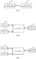
Fig.4 shows a schematic diagram of a first communication device according to an embodiment of the invention. -
Fig.5 shows a schematic diagram of a first user equipment according to an embodiment of the invention. -
Fig.6 shows a schematic diagram of a second communication device according to an embodiment of the invention. -
Fig.7 shows a schematic diagram of a second user equipment according to an embodiment of the invention. - In the embodiments of the invention, a base station and/or a UE transmits a signal in a switching duration between a downlink sub-frame and an uplink sub-frame in an unlicensed frequency band to occupy the current channel, so that it can access the current channel, and transmit data, and this solution can be implemented at low complexity, and can address the problem of an uplink (UL) access occasion inferior to that in WIFI, enable the MU-FDM and MU-SDM modes, and avoid a great loss of LAA performance, and a waste of radio resources. The switching duration as referred to in the embodiments of the invention, e.g., a Guard Period (GP), can also be referred to as a switching period of time between a downlink sub-frame and an uplink sub-frame.
- The embodiments of the invention will be described below in further details with reference to the drawings by way of an example in which the switching duration is a GP. It shall be noted that the embodiments described here are merely intended to illustrate and explain the invention, but not to limit the invention thereto.
- As illustrated in
Fig.1 , a method for transmitting data according to an embodiment of the invention includes: - in the operation S11, a communication device transmits a signal in a GP between a downlink sub-frame and an uplink sub-frame to occupy the current channel; and
- in the operation S12, the communication device transmits data over the current channel.
- In the embodiment of the invention, the communication device transmits a signal in a GP between a downlink sub-frame and an uplink sub-frame to occupy the current channel; and the communication device transmits data over the current channel. Apparently the solution according to the embodiment of the invention can be implemented at low complexity, and can address the problem of a UL access occasion inferior to that in WIFI, enable the MU-FDM and MU-SDM modes, and avoid a great loss of LAA performance, and a waste of radio resources.
- It shall be noted that in order to avoid crosstalk between the uplink and the downlink while switching from a downlink sub-frame to an uplink sub-frame in the LTE Time Division Duplex (TDD) transmission mode, a GP needs to be configured between the downlink sub-frame and the uplink sub-frame. The GP is located in a special sub-frame, and the size thereof is determined by a coverage area of a base station; and the GP is of at least one Orthogonal Frequency Division Multiplex (OFDM) symbol in the existing LTE protocol. As specified in the existing LTE protocol, the GP is an idle period, and there is no signal to be transmitted in the GP in a licensed frequency band; but a WIFI device may possibly access the current channel in this period of time in an unlicensed frequency band, and if no LBT operation is expected to be performed in UL transmission, then there may be a period of time of only approximately 20µs allowed between the downlink (DL) and the UL, so in order to avoid the WIFI device from accessing the current channel, a signal can be transmitted in the GP to occupy the current channel, so that the WIFI device detecting the channel can detect the signal, and thus the WIFI device will not occupy the channel.
- Of course, the embodiment of the invention can be applicable to another transmission mode in addition to the LTE TDD transmission mode in an unlicensed frequency band, as long as the transmission mode is such one that in which a GP is configured between a downlink sub-frame and an uplink sub-frame in an uplink and downlink sub-frame configuration.
- In an implementation, the communication device can be a network device, e.g., a base station, etc.; or the communication device can be a user equipment. The two instances, in which the communication device is a network device, and the communication device is a UE, will be described below respectively in details.
- In the first instance, the communication device is a network device.
- Preferably the signal transmitted by the network device in the GP includes a reservation signal indicating that the current channel is occupied.
- Preferably the reservation signal occupies at least a partial OFDM symbol, that is, the reservation signal occupies at least a part of the OFDM symbol.
- If the GP is more than one OFDM symbol, then preferably the signal transmitted by the network device in the GP will further include a downlink signal transmitted from the network device to a user equipment. For example, the network device further transmits a pilot signal in the GP to assist the user equipment in being synchronized, etc.
- In an implementation, the network device transmits the signal in the GP in the following two preferable schemes.
- In a first scheme, the start time of the signal transmission performed by the network device in the GP is the start time of the GP, and there is a first interval between the end time of the signal transmission performed by the network device in the GP and the end time of the GP, where the length of the first interval is less than or equal to that of a preset interval of time, and more than or equal to the smallest length of guard.
- In the embodiment of the invention, the preset interval of time is the largest interval of time in which no CCA detection is performed before the channel is allowed to be occupied.
- In the embodiment of the invention, the smallest length of guard is dependent upon a coverage distance of the system, where the larger the coverage distance is, the larger the smallest length of guard is. The length of the GP is more than or equal to the smallest length of guard, and the GP includes at least one OFDM symbol.
- Preferably in this scheme, the UE may perform uplink transmission without CCA detection in the preset interval of time following the end of a DL signal transmission performed by the network device.
- Preferably the start time of a UL signal transmission performed by the UE is the start time of a uplink sub-frame following the end of the GP, or the start time of a UL signal transmission performed by the UE is in the GP.
- By way of an example, as illustrated in
Fig.2A , the GP is in a special sub-frame, and the base station transmits the reservation signal at the start time of the GP and ends the transmission at the time Xµs (i.e., the first length of interval) before the end time of the GP, where X is less than or equal to the preset interval of time. Accordingly the successfully scheduled UE may perform uplink transmission without CCA detection at the end of the signal transmission performed by the base station. The frame structure has been illustrated schematically, but will not be limited thereto, and the embodiment of the invention can also be applicable to another frame structure which is configured otherwise. - In another preferred implementation, the method further includes:
- the UE performs CCA detection in a timeslot for channel detection, where the timeslot for channel detection is located in the GP, or in a sub-frame following the end of the GP; and
- if the current channel being idle is detected, then the UE will transmit the signal over the current channel; or
- if the current channel being occupied is detected, then the UE will not occupy the current channel.
- By way of an example, as illustrated in
Fig.2B , the base station firstly transmits the reservation signal in the GP, and the successfully scheduled UE detects the current channel in a CCA timeslot in the GP; and if the current channel is idle, then the UE will access the channel, or if the current channel is busy, then the UE will abort the current access. The UE transmits a signal immediately after accessing the channel in the GP, where the signal may be one of a reservation signal, uplink data, or a pilot signal. The base station transmits the reservation signal in the GP, so that an idle period of time in the GP can be shortened to thereby facilitate an access to the channel in the LTE-U system. - In a second scheme, there is a second interval between the start time of the signal transmission performed by the network device in the GP and the start time of the GP, a first interval between the end time of the signal transmission and the end time of the GP, and the sum of the length of the first interval and the second interval is less than or equal to that of a preset interval of time, where the length of the first interval is more than or equal to the smallest length of guard.
- Preferably in this scheme, the UE may directly perform uplink transmission without CCA detection in the preset interval of time following the end of a DL signal transmission performed by the network device.
- By way of an example, as illustrated in
Fig.2C , the GP is in a special sub-frame, and the base station transmits the reservation signal at the time X1µs after the start time of the GP and ends the transmission at the time X2µs before the end time of the GP, where the sum of X1 and X2 is less than or equal to the preset interval of time. Accordingly the successfully scheduled UE may directly perform the uplink transmission without CCA detection at the end of the signal transmission performed by the base station. - In another preferred implementation, the method further includes:
- the UE performs CCA detection in a timeslot for channel detection, where the timeslot for channel detection is located in the GP, or in a sub-frame following the end of the GP; and
- if the current channel being idle is detected, then the UE will transmit the signal over the current channel; or
- if the current channel being occupied is detected, then the UE will not occupy the current channel.
- By way of an example, as illustrated in
Fig.2D , the GP is in a special sub-frame, and the base station transmits the reservation signal at the time X1µs after the start time of the GP and ends the transmission at the time X2µs before the end time of the GP, where the sum of X1 and X2 is less than or equal to the preset interval of time. Accordingly the successfully scheduled UE detects the current channel in a CCA timeslot in the GP; and if the current channel is idle, then the UE will access the channel, or if the current channel is busy, then the UE will abort the current access. The UE transmits a signal immediately after accessing the channel in the GP, where the signal may be one of a reservation signal, uplink data, or a pilot signal. The base station transmits the reservation signal in the GP, so that an idle period of time in the GP can be shortened to thereby facilitate an access to the channel in the LTE-U system. - It shall be noted that the GP in the embodiment of the invention can alternatively be configured at another position than in a special sub-frame. It is determined in CCA detection by energy detection whether there is a signal being transmitted over the current channel to thereby determine whether the channel is occupied.
- In the second instance, the communication device is a UE.
- In this instance, the user equipment transmits the signal in the GP in the following three preferable schemes.
- In a first scheme, the signal transmitted by the user equipment in the GP includes a reservation signal indicating that the current channel is occupied.
- Preferably the reservation signal occupies at least a partial OFDM symbol, that is, the reservation signal occupies at least a part of the OFDM symbol.
- In this scheme, if the GP is more than one OFDM symbol, then preferably the signal transmitted by the user equipment in the GP will further include an uplink signal transmitted from the user equipment to a network device, e.g., uplink data, a pilot signal, etc.
- In this scheme, the user equipment transmits the signal in the GP in the following two preferable implementations.
- 1. The end time of the signal transmission performed by the user equipment in the GP is the end time of the GP, and there is a second interval between the start time of the signal transmission performed by the user equipment in the GP and the start time of the GP, where the length of the second interval is less than or equal to that of a preset interval of time, and more than or equal to the smallest length of guard.
- By way of an example, as illustrated in
Fig.2E , the GP is in a special sub-frame, there is no signal transmitted in first Xµs in the GP (i.e., the length of second interval), and the successfully scheduled UE transmits the reservation signal at the time Xµs after the start time of the GP, where X is less than or equal to the preset interval of time, so that the UE can perform uplink transmission directly without CCA detection at the end of the GP. - 2. The sum of, a length of second interval between the start time of the signal transmission performed by the user equipment in the GP and the start time of the GP, and a length of the first interval between the end time of the signal transmission and the end time of the GP, is less than or equal to a preset interval of time, and more than or equal to the smallest length of guard.
- In a second scheme, the signal transmitted by the UE in the GP is an uplink signal to be transmitted from the UE to a network device in an uplink sub-frame following the end of the GP.
- In this scheme, the UE advances the transmission of the uplink signal to be transmitted from the UE to the network device in the uplink sub-frame following the end of the GP, and transmits the uplink signal in the GP to occupy the current channel. In this scheme, neither the network device nor the user equipment will transmit the reservation signal in the GP.
- In this scheme, the length of the second interval between the start time of the signal transmission performed by the UE in the GP, and the start time of the GP is less than or equal to that of a preset interval of time, and is more than or equal to the smallest length of guard.
- By way of an example, as illustrated in
Fig.2F , the start time of uplink transmission from the UE is advanced from an uplink sub-frame following the end of the GP to the time Xµs following the start time of the GP, where X is less than or equal to the preset interval of time, and more than or equal to the smallest length of guard. Since the start time of UL transmission is advanced, the corresponding end time of UL transmission is also advanced. The start time of UL transmission is advanced without affecting an alignment relationship between a licensed primary carrier and an LAA carrier. - In the first scheme or the second scheme, the UE transmits the signal in the GP to occupy the current channel, so that the UE may perform uplink transmission directly without CCA detection after transmitting the signal.
- In a third scheme, the communication device is a UE, and before the communication device transmits the signal in the GP, the method further includes: the communication device performs CCA detection on the current channel in a timeslot for channel detection in the GP; and
if the current channel being idle is detected, then the UE will transmit the signal; or
if the current channel being occupied is detected, then the UE will not occupy the current channel. - In this scheme, the signal transmitted by the UE includes a reservation signal indicating that the current channel is occupied.
- If the GP is more than one OFDM symbol, then preferably the signal transmitted by the UE in the GP will further include an uplink signal transmitted by the UE to a network device.
- This scheme is preferably applicable in the case that the length of time of downlink transmission from the network device has reached the specified largest channel occupancy period of time, or the smallest length of guard is larger than a preset interval of time.
- By way of an example, as illustrated in
Fig.2G , the successfully scheduled UE performs CCA detection in the GP to detect the channel, and to determine whether the channel is idle, and if the channel is idle, then the UE will access the channel, or if the channel is busy, then the UE will abort the current access. The CCA detection is performed typically from the time a preset interval of time after the start time of the GP. The UE transmits the signal immediately after accessing the channel in the GP, to occupy the channel. - Based upon the same inventive idea, an embodiment of the invention further provides another method for transmitting data, which corresponds to such an executor of the method for transmitting data as illustrated in
Fig.1 that is a communication device. As illustrated inFig.3 , the method includes: - in the operation S31, a UE determines an uplink signal to be transmitted to a network device; and
- in the operation S32, the UE transmits the uplink signal in a GP between a downlink sub-frame and an uplink sub-frame, or after the GP.
- In an implementation, the length of interval between the start time of the uplink signal transmission performed by the UE, and the end time of the signal transmission performed by the network device in the GP is more than or equal to a preset length of guard.
- Preferably before the operation S32, the method further includes: the UE performs CCA detection in a timeslot for channel detection in the GP; and if the current channel being idle is detected, then in the operation S32, the UE will then transmit the uplink signal in the current channel.
- In another implementation, if the current channel being occupied is detected, then the UE will abort accessing the current channel.
- In an implementation, the signal transmitted by the network device includes a reservation signal indicating that the current channel is occupied.
- The signal transmitted by the UE is a reservation signal indicating that the current channel is occupied, or the uplink signal transmitted by the UE to the network device, where the uplink signal transmitted by the UE to the network device can be uplink data, or can be a pilot signal.
- Preferably the signal transmitted by the network device further includes a downlink signal transmitted by the network device to the UE, where the downlink signal transmitted by the network device to the UE can be downlink data, or can be a pilot signal.
- The processing flow of the method above can be performed in software program which can be stored in a storage medium, and when the stored software program is invoked, it performs the operations in the method above.
- Based upon the same inventive conception, an embodiment of the invention further provides a communication device corresponding to the method for transmitting data as illustrated in
Fig. 1 , and as illustrated inFig. .4 , the communication device includes: - a
signal transmitting module 41 configured to transmit a signal in a GP between a downlink sub-frame and an uplink sub-frame to occupy the current channel; and - a
data transmitting module 42 configured to transmit data over the current channel. - In a preferable implementation, the signal includes a reservation signal indicating that the current channel is occupied.
- Preferably if the communication device is a network device, then the signal will further include a downlink signal transmitted from the network device to a UE.
- If the communication device is a UE, then the signal will further include an uplink signal transmitted from the UE to a network device.
- In an implementation, the communication device is a network device, the start time of the signal transmission is the start time of the GP, and there is a first interval between the end time of the signal, and the end time of the GP, where the length of the first interval is less than or equal to that of a preset interval of time, and more than or equal to the smallest length of guard.
- In an implementation, if the communication device is a network device, then the sum of the length of a second interval and a first interval will be less than or equal to that of a preset interval of time, where the length of the first interval is more than or equal to the smallest length of guard; or if the communication device is a UE, then the sum of the length of a second interval and a first interval will be less than or equal to that of a preset interval of time, where the length of the second interval is more than or equal to the smallest length of guard;
where the length of the first interval is the length of interval between the end time of the signal transmission, and the end time of the GP, and the length of the second interval is the length of interval between the start time of the signal transmission, and the start time of the GP. - In an implementation, the communication device is a UE, and there is a second interval between the start time of the signal transmission and the start time of the GP, where the length of the second interval is less than or equal to that of a preset interval of time, and more than or equal to the smallest length of guard.
- Preferably the communication device is a UE, and the communication device further includes:
- a CCA detecting module configured to perform CCA detection on the current channel in a timeslot for channel detection in the GP; and
- the signal transmitting module is configured to transmit the signal in the GP if the CCA detecting module detects the current channel being idle.
- In another preferable implementation, the communication device is a UE, the signal is an uplink signal to be transmitted by the UE to a network device in an uplink sub-frame following the end of the GP, and there is a second interval between the start time of the signal transmission and the start time of the GP, where the length of the second interval is less than or equal to that of a preset interval of time.
- Based upon the same inventive idea, an embodiment of the invention further provides a UE corresponding to the method for transmitting data as illustrated in
Fig.3 , and as illustrated inFig.5 , the UE includes: - an uplink
signal determining module 51 configured to determine an uplink signal to be transmitted to a network device; and - an uplink
signal transmitting module 52 configured to transmit the uplink signal in a GP between a downlink sub-frame and an uplink sub-frame, or after the GP. - In an implementation, the length of interval between the start time of the uplink signal transmission, and the end time of the signal transmission performed by the network device in the GP is more than or equal to a preset length of guard.
- Preferably the UE further includes:
- a CCA detecting module configured to perform CCA detection in a timeslot for channel detection in the GP; and
- the uplink signal transmitting module is further configured to transmit the uplink signal over the current channel if the CCA detecting module detects the current channel being idle.
- In an implementation, the signal transmitted by the network device includes a reservation signal indicating that the current channel is occupied.
- The signal transmitted by the UE includes a reservation signal indicating that the current channel is occupied, or the uplink signal transmitted by the user equipment to the network device.
- Preferably the signal transmitted by the network device further includes a downlink signal transmitted by the network device to the UE.
- The structure of and processing in the communication device according to the embodiment of the invention corresponding to the method for transmitting data as illustrated in
Fig.1 will be described below in connection with a preferable hardware structure thereof. - In an embodiment as illustrated in
Fig.6 , the communication device includes atransceiver 61, and at least oneprocessor 62 connected with thetransceiver 61, where:
theprocessor 62 is configured to read and execute program in a memory 63:
to trigger thetransceiver 61 to transmit a signal in a GP between a downlink sub-frame and an uplink sub-frame to occupy the current channel; and to transmit data over the current channel. - Here in
Fig.6 , the bus architecture can include any number of interconnecting buses and bridges to particularly link together various circuits including one or more processors represented by theprocessor 62, and one or more memories represented by thememory 63. The bus architecture can further link together various other circuits, e.g., peripheral devices, manostats, power management circuits, etc., all of which are well known in the art, so a further description thereof will be omitted in this context. The bus interface serves as an interface. Thetransceiver 61 can include a quantity of elements, e.g., a transmitter and a receiver, which are units for communication with various other devices over a transmission medium. - The
processor 62 is responsible for managing the bus architecture and performing normal processes, and thememory 63 can store data for use by theprocessor 62 in performing the operations. - In a preferable implementation, the signal includes a reservation signal indicating that the current channel is occupied.
- Preferably if the communication device is a network device, then the signal will further include a downlink signal transmitted from the network device to a UE.
- If the communication device is a UE, then the signal will further include an uplink signal transmitted from the UE to a network device.
- In an implementation, the communication device is a network device, the start time of the signal transmission is the start time of the GP, and there is a first interval between the end time of the signal transmission and the end time of the GP, where the length of the first interval is less than or equal to that of a preset interval of time, and more than or equal to the smallest length of guard.
- In an implementation, if the communication device is a network device, then the sum of the length of the second interval and the first interval will be less than or equal to that of a preset interval of time, and the length of the first interval is more than or equal to the smallest length of guard; or if the communication device is a UE, then the sum of the length of the second interval and the first interval will be less than or equal to that of a preset interval of time, and the length of the second interval is more than or equal to the smallest length of guard;
where the length of the first interval is the length of interval between the end time of the signal transmission and the end time of the GP, and the length of the second interval is the length of interval between the start time of the signal transmission and the start time of the GP. - In an implementation, the communication device is a UE, and there is a second interval between the start time of the signal transmission and the start time of the GP, where the length of the second interval is less than or equal to that of a preset interval of time, and more than or equal to the smallest length of guard.
- Preferably the communication device is a UE, and the
processor 62 is further configured: to perform CCA detection on the current channel in a timeslot for channel detection in the GP; and to transmit the signal in the GP if the current channel being idle is detected. - In another preferable implementation, the communication device is a UE, the signal is an uplink signal to be transmitted by the UE to a network device in an uplink sub-frame following the end of the GP, and there is a length of the second interval between the start time of the signal transmission and the start time of the GP, where the length of the second interval is less than or equal to a preset interval of time.
- The structure of and processing in the UE according to the embodiment of the invention corresponding to the method for transmitting data as illustrated in
Fig.3 will be described below in connection with a preferable hardware structure thereof. - In an embodiment as illustrated in
Fig.7 , the UE includes atransceiver 71, and at least oneprocessor 72 connected with thetransceiver 71, where:
theprocessor 72 is configured to read and execute program in a memory 73:
to determine an uplink signal to be transmitted to a network device; and to trigger thetransceiver 71 to transmit the uplink signal in a GP between a downlink sub-frame and an uplink sub-frame, or after the GP. - Here in
Fig.7 , the bus architecture can include any number of interconnecting buses and bridges to particularly link together various circuits including one or more processors represented by theprocessor 72, and one or more memories represented by thememory 73. The bus architecture can further link together various other circuits, e.g., peripheral devices, manostats, power management circuits, etc., all of which are well known in the art, so a further description thereof will be omitted in this context. The bus interface serves as an interface. Thetransceiver 71 can include a number of elements, e.g., a transmitter and a receiver, which are units for communication with various other devices over a transmission medium. - The
processor 72 is responsible for managing the bus architecture and performing normal processes, and thememory 73 can store data for use by theprocessor 72 in performing the operations. - In an implementation, the length of interval between the start time of the uplink signal transmission, and the end time of the signal transmission performed by the network device in the GP is more than or equal to a preset length of guard.
- Preferably the
processor 72 is further configured:
to perform CCA detection in a timeslot for channel detection in the GP; and to trigger thetransceiver 71 to transmit the uplink signal over the current channel if the current channel being idle is detected. - In an implementation, the signal transmitted by the network device includes a reservation signal indicating that the current channel is occupied.
- The signal transmitted by the UE includes a reservation signal indicating that the current channel is occupied, or the uplink signal transmitted by the user equipment to the network device.
- Preferably the signal transmitted by the network device further includes a downlink signal transmitted by the network device to the UE.
- Those skilled in the art shall appreciate that the embodiments of the invention can be embodied as a method, a system or a computer program product. Therefore the invention can be embodied in the form of an all-hardware embodiment, an all-software embodiment or an embodiment of software and hardware in combination. Furthermore the invention can be embodied in the form of a computer program product embodied in one or more computer useable storage mediums (including but not limited to a disk memory, a CD-ROM, an optical memory, etc.) in which computer useable program codes are contained.
- The invention has been described in a flow chart and/or a block diagram of the method, the device (system) and the computer program product according to the embodiments of the invention. It shall be appreciated that respective flows and/or blocks in the flow chart and/or the block diagram and combinations of the flows and/or the blocks in the flow chart and/or the block diagram can be embodied in computer program instructions. These computer program instructions can be loaded onto a general-purpose computer, a specific-purpose computer, an embedded processor or a processor of another programmable data processing device to produce a machine so that the instructions executed on the computer or the processor of the other programmable data processing device create means for performing the functions specified in the flow(s) of the flow chart and/or the block(s) of the block diagram.
- These computer program instructions can also be stored into a computer readable memory capable of directing the computer or the other programmable data processing device to operate in a specific manner so that the instructions stored in the computer readable memory create an article of manufacture including instruction means which perform the functions specified in the flow(s) of the flow chart and/or the block(s) of the block diagram.
- These computer program instructions can also be loaded onto the computer or the other programmable data processing device so that a series of operational steps are performed on the computer or the other programmable data processing device to create a computer implemented process so that the instructions executed on the computer or the other programmable device provide steps for performing the functions specified in the flow(s) of the flow chart and/or the block(s) of the block diagram.
- Although the preferred embodiments of the invention have been described, those skilled in the art benefiting from the underlying inventive concept can make additional modifications and variations to these embodiments.
Claims (6)
- A method for transmitting data, the method comprising:transmitting (S11), by a communication device, a signal in a switching duration between a downlink sub-frame and an uplink sub-frame to occupy a current channel; andtransmitting (S12), by the communication device, data over the current channel;characterized in that, when the communication device is a network device, start time of a signal transmission is start time of the switching duration, and there is a first interval between end time of the signal transmission and end time of the switching duration, where a length of the first interval is less than or equal to that of a preset interval of time, more than or equal to a smallest length of guard;or,when the communication device is a network device, then a sum of length of a second interval and a first interval is less than or equal to that of a preset interval of time, and the length of the first interval is more than or equal to a smallest length of guard;when the communication device is a User Equipment, UE, then the sum of the length of the second interval and the first interval is less than or equal to that of the preset interval of time, and the length of the second interval is more than or equal to the smallest length of guard;wherein the length of the first interval is a length of interval between end time of the signal transmission and end time of the switching duration, and the length of the second interval is a length of interval between start time of a signal transmission and start time of the switching duration;or,when the communication device is a User Equipment, UE, there is a second interval between start time of a signal transmission, and start time of the switching duration, wherein a length of the second interval is less than or equal to that of a preset interval of time, and more than or equal to a smallest length of guard;or,when the communication device is a User Equipment, UE, the signal is an uplink signal to be transmitted by the UE to a network device in an uplink sub-frame following an end of the switching duration, and a length of a second interval between start time of a signal transmission, and start time of the switching duration is less than or equal to that of a preset interval of time.
- The method according to claim 1, wherein the signal comprises a reservation signal indicating that the current channel is occupied;
wherein if the communication device is a network device, then the signal further comprises a downlink signal transmitted from the network device to a User Equipment, UE; and if the communication device is a UE, the signal further comprises an uplink signal transmitted from the UE to a network device. - The method according to claim 1 or 2, wherein when the communication device is a User Equipment, UE;
before the communication device transmits the signal in the switching duration, the method further comprises: performing, by the communication device, Clear Channel Assessment, CCA, detection on the current channel in a timeslot for channel detection in the switching duration; and
transmitting, by the communication device, the signal in the switching duration comprises:
transmitting, by the communication device, the signal in the switching duration if the current channel being idle is detected. - A communication device, comprising:a signal transmitting module (41) configured to transmit a signal in a switching duration between a downlink sub-frame and an uplink sub-frame to occupy a current channel; anda data transmitting module (42) configured to transmit data over the current channel;characterized in that, when the communication device is a network device, start time of a signal transmission is start time of the switching duration, and there is a first interval between end time of the signal transmission and end time of the switching duration, where a length of the first interval is less than or equal to that of a preset interval of time, more than or equal to a smallest length of guard;or,when the communication device is a network device, then a sum of length of a second interval and a first interval is less than or equal to that of a preset interval of time, and the length of the first interval is more than or equal to a smallest length of guard; when the communication device is a User Equipment, UE, then the sum of the length of the second interval and the first interval is less than or equal to that of the preset interval of time, and the length of the second interval is more than or equal to the smallest length of guard;wherein the length of the first interval is a length of interval between end time of the signal transmission and end time of the switching duration, and the length of the second interval is a length of interval between start time of a signal transmission and start time of the switching duration;or,when the communication device is a User Equipment, UE, there is a second interval between start time of a signal transmission, and start time of the switching duration, wherein a length of the second interval is less than or equal to that of a preset interval of time, and more than or equal to a smallest length of guard;or,when the communication device is a User Equipment, UE, the signal is an uplink signal to be transmitted by the UE to a network device in an uplink sub-frame following an end of the switching duration, and a length of a second interval between start time of a signal transmission, and start time of the switching duration is less than or equal to that of a preset interval of time.
- The communication device according to claim 4, wherein the signal comprises a reservation signal indicating that the current channel is occupied;
wherein if the communication device is a network device, the signal further comprises a downlink signal transmitted from the network device to a User Equipment, UE; and
if the communication device is a UE, the signal further comprises an uplink signal transmitted from the UE to a network device. - The communication device according to claim 4 or 5, wherein when the communication device is a User Equipment, UE, and the communication device further comprises:a Clear Channel Assessment, CCA, detecting module configured to perform CCA detection on the current channel in a timeslot for channel detection in the switching duration; andthe signal transmitting module is configured to transmit the signal in the switching duration if the CCA detecting module detects the current channel being idle.
Applications Claiming Priority (2)
| Application Number | Priority Date | Filing Date | Title |
|---|---|---|---|
| CN201510464450.0A CN106413118B (en) | 2015-07-31 | 2015-07-31 | Data transmission method and device |
| PCT/CN2016/090306 WO2017020695A1 (en) | 2015-07-31 | 2016-07-18 | Data transmission method and device |
Publications (3)
| Publication Number | Publication Date |
|---|---|
| EP3331309A1 EP3331309A1 (en) | 2018-06-06 |
| EP3331309A4 EP3331309A4 (en) | 2018-07-11 |
| EP3331309B1 true EP3331309B1 (en) | 2020-06-17 |
Family
ID=57943783
Family Applications (1)
| Application Number | Title | Priority Date | Filing Date |
|---|---|---|---|
| EP16832183.4A Active EP3331309B1 (en) | 2015-07-31 | 2016-07-18 | Data transmission method and device |
Country Status (6)
| Country | Link |
|---|---|
| US (1) | US10820350B2 (en) |
| EP (1) | EP3331309B1 (en) |
| JP (1) | JP6854287B2 (en) |
| KR (1) | KR102104283B1 (en) |
| CN (1) | CN106413118B (en) |
| WO (1) | WO2017020695A1 (en) |
Families Citing this family (8)
| Publication number | Priority date | Publication date | Assignee | Title |
|---|---|---|---|---|
| US10517021B2 (en) | 2016-06-30 | 2019-12-24 | Evolve Cellular Inc. | Long term evolution-primary WiFi (LTE-PW) |
| CN110062464B (en) * | 2018-01-19 | 2023-05-09 | 华为技术有限公司 | Method and apparatus for managing channel occupation duration of unlicensed band |
| CN116506087A (en) * | 2018-01-19 | 2023-07-28 | 华为技术有限公司 | Method and apparatus for managing channel occupation duration of unlicensed band |
| WO2020047020A1 (en) * | 2018-08-28 | 2020-03-05 | Intel Corporation | Apparatus and method for multefire industry release (mfir) |
| CN110891316B (en) | 2018-09-10 | 2023-11-03 | 华为技术有限公司 | Time domain resource allocation method and access network equipment |
| CN110972327B (en) * | 2018-09-28 | 2022-03-11 | 维沃移动通信有限公司 | Signal transmission method and communication equipment based on unauthorized frequency band |
| WO2021092599A1 (en) * | 2019-11-08 | 2021-05-14 | Qualcomm Incorporated | Cyclic prefix extensions for unlicensed spectrum |
| WO2021184323A1 (en) | 2020-03-19 | 2021-09-23 | Oppo广东移动通信有限公司 | Data sending method and terminal device |
Family Cites Families (20)
| Publication number | Priority date | Publication date | Assignee | Title |
|---|---|---|---|---|
| JP3530141B2 (en) * | 2001-03-06 | 2004-05-24 | 松下電器産業株式会社 | Wireless LAN system and wireless LAN system signal collision avoidance method |
| EP1746743B1 (en) | 2005-07-21 | 2010-01-06 | Mitsubishi Electric R&D Centre Europe B.V. | Method for transmission in a TDD system with variable length guard period |
| CN101399607B (en) * | 2007-09-29 | 2013-01-02 | 北京信威通信技术股份有限公司 | Effective distance measuring method and device in wireless communication system |
| JP2011120064A (en) | 2009-12-04 | 2011-06-16 | Mitsubishi Electric Corp | Transmission terminal, wireless communication system, and transmission method |
| US8737321B2 (en) * | 2010-04-22 | 2014-05-27 | Nokia Corporation | Channel reservation in time division duplex wireless communication system |
| US10314077B2 (en) * | 2013-05-20 | 2019-06-04 | Qualcomm Incorporated | Gating scheme for wireless communication over unlicensed spectrum |
| US20150223075A1 (en) * | 2014-01-31 | 2015-08-06 | Intel IP Corporation | Systems, methods and devices for channel reservation |
| US9814093B2 (en) * | 2014-01-15 | 2017-11-07 | Electronics And Telecommunications Research Institute | Data frame structure and operation method for sharing unlicensed spectrum in wireless communication system and apparatus thereof |
| CN104812049B (en) * | 2014-01-24 | 2018-10-12 | 中国移动通信集团公司 | A kind of method and apparatus of synchronization among base stations |
| US9609666B2 (en) * | 2014-03-03 | 2017-03-28 | Futurewei Technologies, Inc. | System and method for reserving a channel for coexistence of U-LTE and Wi-Fi |
| EP3866381A1 (en) * | 2014-05-08 | 2021-08-18 | Nokia Solutions and Networks Oy | Improving communication efficiency |
| US10057779B2 (en) * | 2014-06-13 | 2018-08-21 | Qualcomm Incorporated | Techniques for enhancing frame structure and listen before talk procedure (LBT) for transmissions using an unlicensed radio frequency spectrum band |
| WO2015199494A1 (en) | 2014-06-26 | 2015-12-30 | 엘지전자 주식회사 | Method and device for transmitting data in unlicensed band |
| EP3177061B1 (en) * | 2014-07-31 | 2020-02-26 | NTT DoCoMo, Inc. | User terminal, wireless communication system, and wireless communication method |
| US9565568B2 (en) * | 2014-11-14 | 2017-02-07 | Blackberry Limited | Sharing channels in a licensed-assisted access in long term evolution operation |
| CN105721376B (en) * | 2014-12-05 | 2019-06-14 | 中国移动通信集团公司 | Based on the unlicensed spectrum interference avoidance method of TDD transmission mode and base station |
| CN104486013B (en) * | 2014-12-19 | 2017-01-04 | 宇龙计算机通信科技(深圳)有限公司 | Channel detection method, Channel Detection system, terminal and base station |
| CN110266462B (en) * | 2015-05-12 | 2021-08-24 | 韩国电子通信研究院 | Transmitter transmission method and method performed by receiver through unlicensed band channel |
| US20160353437A1 (en) * | 2015-05-26 | 2016-12-01 | Futurewei Technologies, Inc. | System and Method for Reserving Unlicensed Spectrum |
| US10020923B2 (en) * | 2015-07-30 | 2018-07-10 | Lg Electronics Inc. | Method of transmitting and receiving downlink signal in unlicensed band in wireless communication system and apparatus therefor |
-
2015
- 2015-07-31 CN CN201510464450.0A patent/CN106413118B/en active Active
-
2016
- 2016-07-18 WO PCT/CN2016/090306 patent/WO2017020695A1/en active Application Filing
- 2016-07-18 US US15/749,056 patent/US10820350B2/en active Active
- 2016-07-18 KR KR1020187005994A patent/KR102104283B1/en active IP Right Grant
- 2016-07-18 JP JP2018524518A patent/JP6854287B2/en active Active
- 2016-07-18 EP EP16832183.4A patent/EP3331309B1/en active Active
Non-Patent Citations (1)
| Title |
|---|
| None * |
Also Published As
| Publication number | Publication date |
|---|---|
| EP3331309A4 (en) | 2018-07-11 |
| JP2018525953A (en) | 2018-09-06 |
| US20180220464A1 (en) | 2018-08-02 |
| JP6854287B2 (en) | 2021-04-07 |
| CN106413118A (en) | 2017-02-15 |
| KR102104283B1 (en) | 2020-04-24 |
| WO2017020695A1 (en) | 2017-02-09 |
| US10820350B2 (en) | 2020-10-27 |
| CN106413118B (en) | 2020-01-17 |
| KR20180034639A (en) | 2018-04-04 |
| EP3331309A1 (en) | 2018-06-06 |
Similar Documents
| Publication | Publication Date | Title |
|---|---|---|
| EP3331309B1 (en) | Data transmission method and device | |
| US11197320B2 (en) | Uplink transmission resource scheduling method and device, and uplink transmission method and device | |
| EP3094124B1 (en) | Data processing method and device | |
| US9924547B2 (en) | Channel access method and access point | |
| US20170094546A1 (en) | Enabling long-term-evolution/wifi coexistence | |
| US10917916B2 (en) | Method and device for transmitting PRACH signals in unauthorized spectrum | |
| EP3277045B1 (en) | Method and device for preempting transmission resources on unlicensed carriers | |
| CN110505026B (en) | Signal interception method, related equipment and system | |
| US10542438B2 (en) | Method for detecting signal on unlicensed spectrum channel, user equipment, and base station | |
| KR102386383B1 (en) | Method and apparatus of transmitting data in wireless communication system | |
| CN107926042B (en) | Transmitter and receiver for wireless communication system | |
| KR101126568B1 (en) | Mobile station, radio access network device, and mobile communication system | |
| RU2763959C1 (en) | Method for communication and communication apparatus | |
| US20080181192A1 (en) | Radio communication apparatus and radio communication method | |
| EP4014665A1 (en) | Apparatuses and methods for wireless communications | |
| EP3915310B1 (en) | Cooperative inter-network channel selection | |
| CN109076350B (en) | Uplink transmission method and device based on authorization-assisted access LAA system | |
| EP3673698B1 (en) | Methods and nodes for communication on multiple channels | |
| CN107079300B (en) | Method and communication device for communication using spectrum resources | |
| WO2016169400A1 (en) | Channel access method and apparatus | |
| EP3079437B1 (en) | Method and device for data transmission | |
| WO2016165365A1 (en) | Method, base station and system for preempting unlicensed carrier | |
| KR20160054396A (en) | Method and apparatus for transmitting data through unlicensed band |
Legal Events
| Date | Code | Title | Description |
|---|---|---|---|
| STAA | Information on the status of an ep patent application or granted ep patent |
Free format text: STATUS: THE INTERNATIONAL PUBLICATION HAS BEEN MADE |
|
| PUAI | Public reference made under article 153(3) epc to a published international application that has entered the european phase |
Free format text: ORIGINAL CODE: 0009012 |
|
| STAA | Information on the status of an ep patent application or granted ep patent |
Free format text: STATUS: REQUEST FOR EXAMINATION WAS MADE |
|
| 17P | Request for examination filed |
Effective date: 20180222 |
|
| AK | Designated contracting states |
Kind code of ref document: A1 Designated state(s): AL AT BE BG CH CY CZ DE DK EE ES FI FR GB GR HR HU IE IS IT LI LT LU LV MC MK MT NL NO PL PT RO RS SE SI SK SM TR |
|
| AX | Request for extension of the european patent |
Extension state: BA ME |
|
| REG | Reference to a national code |
Ref country code: DE Ref legal event code: R079 Ref document number: 602016038429 Country of ref document: DE Free format text: PREVIOUS MAIN CLASS: H04W0074000000 Ipc: H04W0074080000 |
|
| A4 | Supplementary search report drawn up and despatched |
Effective date: 20180613 |
|
| RIC1 | Information provided on ipc code assigned before grant |
Ipc: H04W 74/08 20090101AFI20180607BHEP |
|
| DAV | Request for validation of the european patent (deleted) | ||
| DAX | Request for extension of the european patent (deleted) | ||
| GRAP | Despatch of communication of intention to grant a patent |
Free format text: ORIGINAL CODE: EPIDOSNIGR1 |
|
| STAA | Information on the status of an ep patent application or granted ep patent |
Free format text: STATUS: GRANT OF PATENT IS INTENDED |
|
| INTG | Intention to grant announced |
Effective date: 20200107 |
|
| GRAS | Grant fee paid |
Free format text: ORIGINAL CODE: EPIDOSNIGR3 |
|
| GRAA | (expected) grant |
Free format text: ORIGINAL CODE: 0009210 |
|
| STAA | Information on the status of an ep patent application or granted ep patent |
Free format text: STATUS: THE PATENT HAS BEEN GRANTED |
|
| AK | Designated contracting states |
Kind code of ref document: B1 Designated state(s): AL AT BE BG CH CY CZ DE DK EE ES FI FR GB GR HR HU IE IS IT LI LT LU LV MC MK MT NL NO PL PT RO RS SE SI SK SM TR |
|
| REG | Reference to a national code |
Ref country code: GB Ref legal event code: FG4D |
|
| REG | Reference to a national code |
Ref country code: CH Ref legal event code: EP |
|
| REG | Reference to a national code |
Ref country code: IE Ref legal event code: FG4D |
|
| REG | Reference to a national code |
Ref country code: DE Ref legal event code: R096 Ref document number: 602016038429 Country of ref document: DE |
|
| REG | Reference to a national code |
Ref country code: AT Ref legal event code: REF Ref document number: 1282896 Country of ref document: AT Kind code of ref document: T Effective date: 20200715 |
|
| PG25 | Lapsed in a contracting state [announced via postgrant information from national office to epo] |
Ref country code: SE Free format text: LAPSE BECAUSE OF FAILURE TO SUBMIT A TRANSLATION OF THE DESCRIPTION OR TO PAY THE FEE WITHIN THE PRESCRIBED TIME-LIMIT Effective date: 20200617 Ref country code: NO Free format text: LAPSE BECAUSE OF FAILURE TO SUBMIT A TRANSLATION OF THE DESCRIPTION OR TO PAY THE FEE WITHIN THE PRESCRIBED TIME-LIMIT Effective date: 20200917 Ref country code: LT Free format text: LAPSE BECAUSE OF FAILURE TO SUBMIT A TRANSLATION OF THE DESCRIPTION OR TO PAY THE FEE WITHIN THE PRESCRIBED TIME-LIMIT Effective date: 20200617 Ref country code: GR Free format text: LAPSE BECAUSE OF FAILURE TO SUBMIT A TRANSLATION OF THE DESCRIPTION OR TO PAY THE FEE WITHIN THE PRESCRIBED TIME-LIMIT Effective date: 20200918 Ref country code: FI Free format text: LAPSE BECAUSE OF FAILURE TO SUBMIT A TRANSLATION OF THE DESCRIPTION OR TO PAY THE FEE WITHIN THE PRESCRIBED TIME-LIMIT Effective date: 20200617 |
|
| REG | Reference to a national code |
Ref country code: LT Ref legal event code: MG4D |
|
| REG | Reference to a national code |
Ref country code: NL Ref legal event code: MP Effective date: 20200617 |
|
| PG25 | Lapsed in a contracting state [announced via postgrant information from national office to epo] |
Ref country code: LV Free format text: LAPSE BECAUSE OF FAILURE TO SUBMIT A TRANSLATION OF THE DESCRIPTION OR TO PAY THE FEE WITHIN THE PRESCRIBED TIME-LIMIT Effective date: 20200617 Ref country code: RS Free format text: LAPSE BECAUSE OF FAILURE TO SUBMIT A TRANSLATION OF THE DESCRIPTION OR TO PAY THE FEE WITHIN THE PRESCRIBED TIME-LIMIT Effective date: 20200617 Ref country code: HR Free format text: LAPSE BECAUSE OF FAILURE TO SUBMIT A TRANSLATION OF THE DESCRIPTION OR TO PAY THE FEE WITHIN THE PRESCRIBED TIME-LIMIT Effective date: 20200617 Ref country code: BG Free format text: LAPSE BECAUSE OF FAILURE TO SUBMIT A TRANSLATION OF THE DESCRIPTION OR TO PAY THE FEE WITHIN THE PRESCRIBED TIME-LIMIT Effective date: 20200917 |
|
| REG | Reference to a national code |
Ref country code: AT Ref legal event code: MK05 Ref document number: 1282896 Country of ref document: AT Kind code of ref document: T Effective date: 20200617 |
|
| PG25 | Lapsed in a contracting state [announced via postgrant information from national office to epo] |
Ref country code: NL Free format text: LAPSE BECAUSE OF FAILURE TO SUBMIT A TRANSLATION OF THE DESCRIPTION OR TO PAY THE FEE WITHIN THE PRESCRIBED TIME-LIMIT Effective date: 20200617 Ref country code: AL Free format text: LAPSE BECAUSE OF FAILURE TO SUBMIT A TRANSLATION OF THE DESCRIPTION OR TO PAY THE FEE WITHIN THE PRESCRIBED TIME-LIMIT Effective date: 20200617 |
|
| PG25 | Lapsed in a contracting state [announced via postgrant information from national office to epo] |
Ref country code: EE Free format text: LAPSE BECAUSE OF FAILURE TO SUBMIT A TRANSLATION OF THE DESCRIPTION OR TO PAY THE FEE WITHIN THE PRESCRIBED TIME-LIMIT Effective date: 20200617 Ref country code: SM Free format text: LAPSE BECAUSE OF FAILURE TO SUBMIT A TRANSLATION OF THE DESCRIPTION OR TO PAY THE FEE WITHIN THE PRESCRIBED TIME-LIMIT Effective date: 20200617 Ref country code: IT Free format text: LAPSE BECAUSE OF FAILURE TO SUBMIT A TRANSLATION OF THE DESCRIPTION OR TO PAY THE FEE WITHIN THE PRESCRIBED TIME-LIMIT Effective date: 20200617 Ref country code: RO Free format text: LAPSE BECAUSE OF FAILURE TO SUBMIT A TRANSLATION OF THE DESCRIPTION OR TO PAY THE FEE WITHIN THE PRESCRIBED TIME-LIMIT Effective date: 20200617 Ref country code: ES Free format text: LAPSE BECAUSE OF FAILURE TO SUBMIT A TRANSLATION OF THE DESCRIPTION OR TO PAY THE FEE WITHIN THE PRESCRIBED TIME-LIMIT Effective date: 20200617 Ref country code: CZ Free format text: LAPSE BECAUSE OF FAILURE TO SUBMIT A TRANSLATION OF THE DESCRIPTION OR TO PAY THE FEE WITHIN THE PRESCRIBED TIME-LIMIT Effective date: 20200617 Ref country code: AT Free format text: LAPSE BECAUSE OF FAILURE TO SUBMIT A TRANSLATION OF THE DESCRIPTION OR TO PAY THE FEE WITHIN THE PRESCRIBED TIME-LIMIT Effective date: 20200617 Ref country code: PT Free format text: LAPSE BECAUSE OF FAILURE TO SUBMIT A TRANSLATION OF THE DESCRIPTION OR TO PAY THE FEE WITHIN THE PRESCRIBED TIME-LIMIT Effective date: 20201019 |
|
| PG25 | Lapsed in a contracting state [announced via postgrant information from national office to epo] |
Ref country code: IS Free format text: LAPSE BECAUSE OF FAILURE TO SUBMIT A TRANSLATION OF THE DESCRIPTION OR TO PAY THE FEE WITHIN THE PRESCRIBED TIME-LIMIT Effective date: 20201017 Ref country code: PL Free format text: LAPSE BECAUSE OF FAILURE TO SUBMIT A TRANSLATION OF THE DESCRIPTION OR TO PAY THE FEE WITHIN THE PRESCRIBED TIME-LIMIT Effective date: 20200617 Ref country code: SK Free format text: LAPSE BECAUSE OF FAILURE TO SUBMIT A TRANSLATION OF THE DESCRIPTION OR TO PAY THE FEE WITHIN THE PRESCRIBED TIME-LIMIT Effective date: 20200617 |
|
| REG | Reference to a national code |
Ref country code: CH Ref legal event code: PL |
|
| REG | Reference to a national code |
Ref country code: DE Ref legal event code: R097 Ref document number: 602016038429 Country of ref document: DE |
|
| PG25 | Lapsed in a contracting state [announced via postgrant information from national office to epo] |
Ref country code: MC Free format text: LAPSE BECAUSE OF FAILURE TO SUBMIT A TRANSLATION OF THE DESCRIPTION OR TO PAY THE FEE WITHIN THE PRESCRIBED TIME-LIMIT Effective date: 20200617 |
|
| PLBE | No opposition filed within time limit |
Free format text: ORIGINAL CODE: 0009261 |
|
| STAA | Information on the status of an ep patent application or granted ep patent |
Free format text: STATUS: NO OPPOSITION FILED WITHIN TIME LIMIT |
|
| REG | Reference to a national code |
Ref country code: BE Ref legal event code: MM Effective date: 20200731 |
|
| PG25 | Lapsed in a contracting state [announced via postgrant information from national office to epo] |
Ref country code: CH Free format text: LAPSE BECAUSE OF NON-PAYMENT OF DUE FEES Effective date: 20200731 Ref country code: DK Free format text: LAPSE BECAUSE OF FAILURE TO SUBMIT A TRANSLATION OF THE DESCRIPTION OR TO PAY THE FEE WITHIN THE PRESCRIBED TIME-LIMIT Effective date: 20200617 Ref country code: LI Free format text: LAPSE BECAUSE OF NON-PAYMENT OF DUE FEES Effective date: 20200731 Ref country code: LU Free format text: LAPSE BECAUSE OF NON-PAYMENT OF DUE FEES Effective date: 20200718 |
|
| 26N | No opposition filed |
Effective date: 20210318 |
|
| PG25 | Lapsed in a contracting state [announced via postgrant information from national office to epo] |
Ref country code: SI Free format text: LAPSE BECAUSE OF FAILURE TO SUBMIT A TRANSLATION OF THE DESCRIPTION OR TO PAY THE FEE WITHIN THE PRESCRIBED TIME-LIMIT Effective date: 20200617 Ref country code: BE Free format text: LAPSE BECAUSE OF NON-PAYMENT OF DUE FEES Effective date: 20200731 |
|
| REG | Reference to a national code |
Ref country code: DE Ref legal event code: R081 Ref document number: 602016038429 Country of ref document: DE Owner name: DATANG MOBILE COMMUNICATIONS EQUIPMENT CO., LT, CN Free format text: FORMER OWNER: CHINA ACADEMY OF TELECOMMUNICATIONS TECHNOLOGY, BEIJING, CN |
|
| PG25 | Lapsed in a contracting state [announced via postgrant information from national office to epo] |
Ref country code: IE Free format text: LAPSE BECAUSE OF NON-PAYMENT OF DUE FEES Effective date: 20200718 |
|
| REG | Reference to a national code |
Ref country code: GB Ref legal event code: 732E Free format text: REGISTERED BETWEEN 20211007 AND 20211013 |
|
| PG25 | Lapsed in a contracting state [announced via postgrant information from national office to epo] |
Ref country code: TR Free format text: LAPSE BECAUSE OF FAILURE TO SUBMIT A TRANSLATION OF THE DESCRIPTION OR TO PAY THE FEE WITHIN THE PRESCRIBED TIME-LIMIT Effective date: 20200617 Ref country code: MT Free format text: LAPSE BECAUSE OF FAILURE TO SUBMIT A TRANSLATION OF THE DESCRIPTION OR TO PAY THE FEE WITHIN THE PRESCRIBED TIME-LIMIT Effective date: 20200617 Ref country code: CY Free format text: LAPSE BECAUSE OF FAILURE TO SUBMIT A TRANSLATION OF THE DESCRIPTION OR TO PAY THE FEE WITHIN THE PRESCRIBED TIME-LIMIT Effective date: 20200617 |
|
| PG25 | Lapsed in a contracting state [announced via postgrant information from national office to epo] |
Ref country code: MK Free format text: LAPSE BECAUSE OF FAILURE TO SUBMIT A TRANSLATION OF THE DESCRIPTION OR TO PAY THE FEE WITHIN THE PRESCRIBED TIME-LIMIT Effective date: 20200617 |
|
| P01 | Opt-out of the competence of the unified patent court (upc) registered |
Effective date: 20230512 |
|
| PGFP | Annual fee paid to national office [announced via postgrant information from national office to epo] |
Ref country code: GB Payment date: 20230721 Year of fee payment: 8 |
|
| PGFP | Annual fee paid to national office [announced via postgrant information from national office to epo] |
Ref country code: FR Payment date: 20230726 Year of fee payment: 8 Ref country code: DE Payment date: 20230719 Year of fee payment: 8 |