EP3331232A1 - Image processing device - Google Patents
Image processing device Download PDFInfo
- Publication number
- EP3331232A1 EP3331232A1 EP16830349.3A EP16830349A EP3331232A1 EP 3331232 A1 EP3331232 A1 EP 3331232A1 EP 16830349 A EP16830349 A EP 16830349A EP 3331232 A1 EP3331232 A1 EP 3331232A1
- Authority
- EP
- European Patent Office
- Prior art keywords
- crease
- detecting unit
- toner peeling
- density
- pixel
- Prior art date
- Legal status (The legal status is an assumption and is not a legal conclusion. Google has not performed a legal analysis and makes no representation as to the accuracy of the status listed.)
- Granted
Links
- 238000012545 processing Methods 0.000 title claims description 28
- 238000009826 distribution Methods 0.000 claims description 24
- 238000005070 sampling Methods 0.000 claims description 23
- 238000001514 detection method Methods 0.000 claims description 14
- 230000007423 decrease Effects 0.000 claims description 2
- 238000010586 diagram Methods 0.000 description 12
- 238000004891 communication Methods 0.000 description 7
- 238000000034 method Methods 0.000 description 4
- 230000006399 behavior Effects 0.000 description 3
- 238000006243 chemical reaction Methods 0.000 description 3
- 238000012986 modification Methods 0.000 description 3
- 230000004048 modification Effects 0.000 description 3
- 238000012937 correction Methods 0.000 description 2
- 230000005540 biological transmission Effects 0.000 description 1
- 239000003086 colorant Substances 0.000 description 1
- 238000009792 diffusion process Methods 0.000 description 1
- 230000003467 diminishing effect Effects 0.000 description 1
- 230000000694 effects Effects 0.000 description 1
- 239000000284 extract Substances 0.000 description 1
- 230000006870 function Effects 0.000 description 1
- 239000000463 material Substances 0.000 description 1
- 230000002093 peripheral effect Effects 0.000 description 1
- 239000007787 solid Substances 0.000 description 1
Images




Classifications
-
- H—ELECTRICITY
- H04—ELECTRIC COMMUNICATION TECHNIQUE
- H04N—PICTORIAL COMMUNICATION, e.g. TELEVISION
- H04N1/00—Scanning, transmission or reproduction of documents or the like, e.g. facsimile transmission; Details thereof
- H04N1/40—Picture signal circuits
- H04N1/409—Edge or detail enhancement; Noise or error suppression
- H04N1/4097—Removing errors due external factors, e.g. dust, scratches
-
- H—ELECTRICITY
- H04—ELECTRIC COMMUNICATION TECHNIQUE
- H04N—PICTORIAL COMMUNICATION, e.g. TELEVISION
- H04N1/00—Scanning, transmission or reproduction of documents or the like, e.g. facsimile transmission; Details thereof
- H04N1/38—Circuits or arrangements for blanking or otherwise eliminating unwanted parts of pictures
-
- H—ELECTRICITY
- H04—ELECTRIC COMMUNICATION TECHNIQUE
- H04N—PICTORIAL COMMUNICATION, e.g. TELEVISION
- H04N1/00—Scanning, transmission or reproduction of documents or the like, e.g. facsimile transmission; Details thereof
- H04N1/40—Picture signal circuits
-
- G—PHYSICS
- G03—PHOTOGRAPHY; CINEMATOGRAPHY; ANALOGOUS TECHNIQUES USING WAVES OTHER THAN OPTICAL WAVES; ELECTROGRAPHY; HOLOGRAPHY
- G03G—ELECTROGRAPHY; ELECTROPHOTOGRAPHY; MAGNETOGRAPHY
- G03G15/00—Apparatus for electrographic processes using a charge pattern
Definitions
- the present invention relates to an image processing apparatus.
- An image processing apparatus corrects a distorted document image scanned from a book document (for example, see PATENT LITERATURE #1).
- PATENT LITERATURE #1 Japanese Patent Application Publication No. 2004-274705 .
- the toner When folding a sheet-shaped printed matter made by fixing toner in an electrographic manner, the toner may be peeled at a folding position.
- a toner peeling part appears in an object drawn with toner such as a character or a figure in the scanned image. In the aforementioned image processing apparatus, such toner peeling part is not corrected.
- the present invention has been conceived in order to solve this problem and provide an image processing apparatus that corrects a toner peeling part that appears on a crease in a document image.
- An image processing apparatus includes: a crease detecting unit that detects a crease in a document image; and a toner peeling detecting unit that (a) detects as a toner peeling part a pixel area on the crease, the pixel area (a1) having a width of the predetermined number of pixels in a direction perpendicular to the crease, (a2) having a background color, and (a3) of which both sides are adjacent to at least two pixels in a direction perpendicular to the crease, the at least two pixels having a color other than the back ground color, and (b) corrects a pixel value of the toner peeling part on the basis of pixel values of at least two pixels adjacent to both sides of the pixel area.
- a toner peeling part that appears on a crease is corrected.
- Fig. 1 shows a block diagram that indicates a configuration of an image processing apparatus according to an embodiment of the present invention.
- the image processing apparatus shown in Fig. 1 includes an image scanning device 1, a storage device 2, a communication device 3, a printing device 4, and a processor 5.
- the image scanning device 1 is an internal device that optically scans a document image of a document, and generates image data (RGB data, here) of the document image.
- the storage device 2 is a device capable of storing data and programs.
- a non-volatile storage medium with a large capacity is used as the storage device 2, such as non-volatile memory or hard disk drive.
- the storage device 2 is enabled, for example, to store the image data of the document image.
- the communication device 3 is a device which performs data communication with an external device.
- a network interface which performs network communication, a modem which performs facsimile communication or the like is used as the communication device 3.
- the printing device 4 performs printing of a document image based on image data of the document image for which image processing has been processed such as color conversion and halftone process for printing.
- the processor 5 is a computer that includes a CPU (Central Processing Unit), a ROM (Read Only Memory), a RAM (Random Access Memory) and the like, loads a program from the ROM or the storage device 2 to the RAM, and executes the program with the CPU and thereby embodies various processing units.
- a scan processing unit 11 a specific local gradation detecting unit 12, a crease detecting unit 13, a toner peeling detecting unit 14, a crease removing unit 15, and an output processing unit 16.
- the scan processing unit 11 controls the image scanning device 1, and thereby obtains a document image and stores image data of the document image in the storage device 2, the RAM, or the like.
- the specific local gradation detecting unit 12 reads image data of the document image, and detects a specific local gradation in a density distribution of a pixel array in a secondary scanning direction at each one of plural sampling positions (i.e. pixel positions) along a primary scanning direction in the document image.
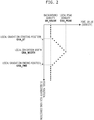
- Fig. 2 shows a diagram that indicates an example of a density distribution of a specific local gradation.
- the aforementioned specific local gradation has a density distribution that monotonically increases from a background density BK_VALUE to a local peak density GRA_PEAK and monotonically decreases from the local peak density GRA_PEAK to the background density BK_VALUE in the secondary scanning direction.
- the background density BK_VALUE is a surface density of a paper sheet of the document or a density of a background image of the document.
- the crease detecting unit 13 detects a crease in a document image. Specifically, the crease detecting unit 13 detects a crease on the basis of positions in the primary scanning direction and positions in the secondary scanning direction of plural specific local gradations detected by the specific local gradation detecting unit 12 for the plural sampling positions along the primary scanning direction.
- the crease detecting unit 13 detects as a crease a linear part that passes at positions of the plural specific local gradations.
- this linear part is an area between a straight line that passes starting positions GRA_ST (see Fig. 2 ) of the respective plural specific local gradations detected at the plural sampling positions and a straight line that passes ending positions GRA_END (see Fig. 2 ) of the respective plural specific local gradations detected at the plural sampling positions.
- the crease detecting unit 13 determines a set of specific local gradations at the respective plural sampling positions so that the specific local gradations have (a) starting positions GRA_ST in the secondary scanning direction that agree with each other within a predetermined error, (b) widths GRA_WIDTH in the secondary scanning direction that agree with each other within a predetermined error, and (c) the local peak densities GRA_PEAK that agree with each other within a predetermined error; and detects a crease on the basis of positions in the primary scanning direction and positions in the secondary scanning direction of the specific local gradations that belong the determined set.
- the crease detecting unit 13 determines plural sets of specific local gradations at the respective plural sampling positions in the aforementioned manner, the crease detecting unit 13 detects plural creases corresponding to the respective determined plural sets.
- the crease detecting unit 13 may determine a set of the detected specific local gradations with the substantially same density distributions, and may detect a crease on the basis of positions in the primary scanning direction and positions in the secondary scanning direction of the specific local gradations that belong the determined set.
- the toner peeling detecting unit 14 detects a toner peeling part on the crease.
- Fig. 3 shows a diagram that indicates an example of a toner peeling part that appears in a document image. If a part of a toner image fixed on a document is peeled, as shown in Fig. 3 , a toner peeling part appears both on an object and on a crease in a document image.
- a toner peeling detecting unit 14 detects this pixel area as a toner peeling part and corrects a pixel value of the toner peeling part on the basis of pixel values of at least two pixels adjacent to both sides of the pixel area. Contrarily, a pixel value of a pixel area that is not detected as a toner peeling part is not changed.
- Fig. 4 shows a diagram that explains detection and correction of a toner peeling part performed by a toner peeling detecting unit 14 shown in Fig. 1 .
- the toner peeling detecting unit 14 uses a detection filter of 5 pixels, for example, and if a target pixel as a center has a background color and all of adjacent residual 4 pixels have a color other than the background color, then it is determined that the target pixel belongs to a toner peeling part.
- the toner peeling detecting unit 14 changes a pixel value of the target pixel to an average value of pixel values of the 4 pixels other than a pixel at the center of the detection filter.
- a detection filter of 5 pixels a detection filter of 3 pixels or a detection filter of 7 pixels or more may be used.
- the width of the aforementioned pixel area and the size of the detection filter are specified as setting data by a user or the like.
- the background color is a surface material color of a paper sheet of the document (e.g. white) or a color of a background image in the document.
- the background color is determined on the basis of colors (i.e. pixel values) of plural lines without any objects (e.g. in a blank part) in the document image.
- the toner peeling detecting unit 14 excludes the crease from a detection target to detect the toner peeling part.
- the density gradient is low, the crease on the document is probably slight and toner peeling hardly appears, and therefore, such a crease is excluded from a detection target of a toner peeling part.
- the toner peeling detecting unit 14 excludes the crease from a detection target to detect the toner peeling part.
- the toner peeling detecting unit 14 corrects a pixel value of the toner peeling part by changing the pixel value to an average value of the at least two pixel adjacent to both sides of the pixel area. Consequently, the toner peeling is removed in the document image.
- the crease removing unit 15 removes the crease detected by the crease detecting unit 13. For example, the crease removing unit 15 replaces a density of the detected crease (i.e. a part having a higher density than a density of its neighborhood) with a density of neighborhood pixels (i.e. background pixels) or with a density obtained by interpolation between neighborhood pixels and thereby removes the crease.
- a density of the detected crease i.e. a part having a higher density than a density of its neighborhood
- neighborhood pixels i.e. background pixels
- the output processing unit 16 For the document image in which such a toner peeling part has been removed and such a crease has been removed, the output processing unit 16 performs image processing necessary for printing such as color conversion (here, color conversion from RGB to CMYK) and halftone process (e.g. binarization process using an error diffusion method), and causes the printing device 4 to perform printing of the document image based on image data of the document image after the image processing.
- image processing necessary for printing such as color conversion (here, color conversion from RGB to CMYK) and halftone process (e.g. binarization process using an error diffusion method)
- the output processing unit 16 may transmit to an external device the image data of the document image in which such a toner peeling part has been removed and such a crease has been removed.
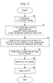
- Fig. 5 shows a flowchart that explains a behavior of the image processing apparatus shown in Fig. 1 .
- the scan processing unit 11 controls the image scanning device 1 and thereby obtains a document image of a document set on the image scanning device 1 and stores image data of the document image in the storage device 2, the RAM, or the like (in Step S1).
- the specific local gradation detecting unit 12 extracts pixel values (i.e. densities) of a pixel array in a secondary scanning direction for the image data of the document image, searches a density distribution of the pixel array for a specific local gradation in the secondary scanning direction, and thereby detects a specific local gradation (in Step S2).
- Fig. 6 shows a diagram that indicates an example of a document image that includes a crease.
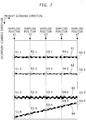
- Fig. 7 shows a diagram that indicates an example of a specific local gradation detected in the document image shown in Fig. 6 .
- a document image shown in Fig. 4 includes four creases, and specific local gradations are detected at each one of five sampling positions including both ends of the document image.
- the number of the sampling positions are 5.
- the number of the sampling positions may be another amount more than 1. In this case, as shown in Fig. 7 , at each one of the sampling positions, four specific local gradations are detected.
- the specific local gradations 51-1 to 51-4 are detected; at the sampling position #2, the specific local gradations 52-1 to 52-4 are detected; at the sampling position #3, the specific local gradations 53-1 to 53-4 are detected; at the sampling position #4, the specific local gradations 54-1 to 54-4 are detected; and at the sampling position #5, the specific local gradations 55-1 to 55-4 are detected.
- the crease detecting unit 13 detects a crease in the aforementioned manner on the basis of positions in the primary scanning direction and positions in the second scanning direction of the plural specific local gradations detected at the respective plural sampling positions (in Step S3).
- a crease 61 is detected on the basis of the specific local gradations 51-1, 52-1, 53-1, 54-1 and 55-1 that have substantially same density distributions as each other
- a crease 62 is detected on the basis of the specific local gradations 51-2, 52-2, 53-2, 54-2 and 55-2 that have substantially same density distributions as each other
- a crease 63 is detected on the basis of the specific local gradations 51-3, 52-3, 53-3, 54-3 and 55-3 that have substantially same density distributions as each other
- a crease 64 is detected on the basis of the specific local gradations 51-4, 52-4, 53-4, 54-4 and 55-4 that have substantially same density distributions as each other
- a crease 65 is detected on the basis of the specific local gradations 51-5, 52-5,
- the toner peeling detecting unit 14 After detecting a crease in the document image as mentioned, the toner peeling detecting unit 14 detects and corrects a toner peeling part in a line of the detected crease in the aforementioned manner (in Step S4).
- the crease removing unit 15 removes the crease detected by the crease detecting unit 13 (in Step S5).
- the output processing unit 16 performs (a) printing of the document image in which a crease has been removed and/or (b) transmission of image data of the document image in which a crease has been removed (in Step S6).
- the crease detecting unit 13 detects a crease in a document image. If on the detected crease a pixel area having a width of the predetermined number of pixels in a direction perpendicular to the crease has a background color, and both sides of the pixel area are adjacent to at least two pixels in a direction perpendicular to the crease and this at least two pixels have a color other than the back ground color, then a toner peeling detecting unit 14 detects this pixel area as a toner peeling part and corrects a pixel value of the toner peeling part on the basis of pixel values of at least two pixels adjacent to both sides of the pixel area.
- the specific local gradation may be limited to a pixel array section that has a density of a pixel at a starting position of the section where a difference between the background density and the density of the pixel at the starting position is equal to or less than a predetermined threshold value.
- a predetermined threshold value if the difference between the background density and the density of the pixel at the starting position exceeds the predetermined threshold value in a pixel array section, then such a pixel array section is not detected as a specific local gradation.
- the specific local gradation may be limited to a pixel array section that has the local peak density that is equal to or less than a predetermined threshold value. In such a case, if the local peak density exceeds the predetermined threshold value in a pixel array section, then such a pixel array section is not detected as a specific local gradation.
- the specific local gradation patter detecting unit 12 and the crease detecting unit 13 may detect a crease in the secondary scanning direction in the same manner, and along the crease in the secondary scanning direction, the toner peeling detecting unit 14 may detect a toner peeling part on the crease.
- the detection method of the crease is not limited to the aforementioned method.
- the present invention is applicable to an image forming apparatus such as a multi function peripheral.
Landscapes
- Engineering & Computer Science (AREA)
- Multimedia (AREA)
- Signal Processing (AREA)
- Control Or Security For Electrophotography (AREA)
- Facsimile Image Signal Circuits (AREA)
- Physics & Mathematics (AREA)
- General Physics & Mathematics (AREA)
- Image Analysis (AREA)
- Microelectronics & Electronic Packaging (AREA)
Abstract
Description
- The present invention relates to an image processing apparatus.
- An image processing apparatus corrects a distorted document image scanned from a book document (for example, see PATENT LITERATURE #1).
- PATENT LITERATURE #1: Japanese Patent Application Publication No.
2004-274705 - When folding a sheet-shaped printed matter made by fixing toner in an electrographic manner, the toner may be peeled at a folding position. When scanning an image of such printed matter, a toner peeling part appears in an object drawn with toner such as a character or a figure in the scanned image. In the aforementioned image processing apparatus, such toner peeling part is not corrected.
- The present invention has been conceived in order to solve this problem and provide an image processing apparatus that corrects a toner peeling part that appears on a crease in a document image.
- An image processing apparatus according to the present invention includes: a crease detecting unit that detects a crease in a document image; and a toner peeling detecting unit that (a) detects as a toner peeling part a pixel area on the crease, the pixel area (a1) having a width of the predetermined number of pixels in a direction perpendicular to the crease, (a2) having a background color, and (a3) of which both sides are adjacent to at least two pixels in a direction perpendicular to the crease, the at least two pixels having a color other than the back ground color, and (b) corrects a pixel value of the toner peeling part on the basis of pixel values of at least two pixels adjacent to both sides of the pixel area.
- According to the present invention, in a document image, a toner peeling part that appears on a crease is corrected.
- These and other objects, features and advantages of the present invention will become more apparent upon reading of the following detailed description along with the accompanied drawings.
-
-
Fig. 1 shows a block diagram that indicates a configuration of an image processing apparatus according to an embodiment of the present invention; -
Fig. 2 shows a diagram that indicates an example of a density distribution of a specific local gradation; -
Fig. 3 shows a diagram that indicates an example of a toner peeling part that appears in a document image; -
Fig. 4 shows a diagram that explains detection and correction of a toner peeling part performed by a tonerpeeling detecting unit 14 shown inFig. 1 ; -
Fig. 5 shows a flowchart that explains a behavior of the image processing apparatus shown inFig. 1 ; -
Fig. 6 shows a diagram that indicates an example of a document image that includes a crease; and -
Fig. 7 shows a diagram that indicates an example of a specific local gradation detected in the document image shown inFig. 6 . - Hereinafter, an embodiment of the present invention will be explained with reference to drawings.
-
Fig. 1 shows a block diagram that indicates a configuration of an image processing apparatus according to an embodiment of the present invention. The image processing apparatus shown inFig. 1 includes animage scanning device 1, astorage device 2, acommunication device 3, aprinting device 4, and aprocessor 5. - The
image scanning device 1 is an internal device that optically scans a document image of a document, and generates image data (RGB data, here) of the document image. - The
storage device 2 is a device capable of storing data and programs. A non-volatile storage medium with a large capacity is used as thestorage device 2, such as non-volatile memory or hard disk drive. Thestorage device 2 is enabled, for example, to store the image data of the document image. - The
communication device 3 is a device which performs data communication with an external device. A network interface which performs network communication, a modem which performs facsimile communication or the like is used as thecommunication device 3. - The
printing device 4 performs printing of a document image based on image data of the document image for which image processing has been processed such as color conversion and halftone process for printing. - The
processor 5 is a computer that includes a CPU (Central Processing Unit), a ROM (Read Only Memory), a RAM (Random Access Memory) and the like, loads a program from the ROM or thestorage device 2 to the RAM, and executes the program with the CPU and thereby embodies various processing units. In this embodiment, in theprocessor 5, ascan processing unit 11, a specific localgradation detecting unit 12, acrease detecting unit 13, a tonerpeeling detecting unit 14, acrease removing unit 15, and anoutput processing unit 16. - The
scan processing unit 11 controls theimage scanning device 1, and thereby obtains a document image and stores image data of the document image in thestorage device 2, the RAM, or the like. - The specific local
gradation detecting unit 12 reads image data of the document image, and detects a specific local gradation in a density distribution of a pixel array in a secondary scanning direction at each one of plural sampling positions (i.e. pixel positions) along a primary scanning direction in the document image. -
Fig. 2 shows a diagram that indicates an example of a density distribution of a specific local gradation. As shown inFig. 2 , the aforementioned specific local gradation has a density distribution that monotonically increases from a background density BK_VALUE to a local peak density GRA_PEAK and monotonically decreases from the local peak density GRA_PEAK to the background density BK_VALUE in the secondary scanning direction. - The background density BK_VALUE is a surface density of a paper sheet of the document or a density of a background image of the document.
- Therefore, for example, even if a section in the pixel array has a higher density than the background density but this section has a density distribution that includes plural peaks, then this section is not detected as a specific local gradation. Consequently, an image object such as photograph having density gradation tends not to be improperly detected as a crease.
- Further, for example, even if a section in the pixel array has a higher density than the background density but this section includes plural successive pixels that have a peak density, then this section is not detected as a specific local gradation. Consequently, an image object such as character or line drawing that has a solid density tends not to be improperly detected as a crease.
- The
crease detecting unit 13 detects a crease in a document image. Specifically, thecrease detecting unit 13 detects a crease on the basis of positions in the primary scanning direction and positions in the secondary scanning direction of plural specific local gradations detected by the specific localgradation detecting unit 12 for the plural sampling positions along the primary scanning direction. - More specifically, if the plural specific local gradations detected at plural sampling positions in the primary scanning direction linearly lay, the
crease detecting unit 13 detects as a crease a linear part that passes at positions of the plural specific local gradations. - For example, this linear part is an area between a straight line that passes starting positions GRA_ST (see
Fig. 2 ) of the respective plural specific local gradations detected at the plural sampling positions and a straight line that passes ending positions GRA_END (seeFig. 2 ) of the respective plural specific local gradations detected at the plural sampling positions. - Further, the
crease detecting unit 13 determines a set of specific local gradations at the respective plural sampling positions so that the specific local gradations have (a) starting positions GRA_ST in the secondary scanning direction that agree with each other within a predetermined error, (b) widths GRA_WIDTH in the secondary scanning direction that agree with each other within a predetermined error, and (c) the local peak densities GRA_PEAK that agree with each other within a predetermined error; and detects a crease on the basis of positions in the primary scanning direction and positions in the secondary scanning direction of the specific local gradations that belong the determined set. - When the
crease detecting unit 13 determines plural sets of specific local gradations at the respective plural sampling positions in the aforementioned manner, thecrease detecting unit 13 detects plural creases corresponding to the respective determined plural sets. - Even if at a part of the sampling positions, the
crease detecting unit 13 does not detect the specific local gradation that has (a) the starting position GRA_ST that agrees within a predetermined error, (b) the width GRA_WIDTH that agrees within a predetermined error, and (c) the local peak density GRA_PEAK that agrees within predetermined error (namely, does not detect a specific local gradation that has the substantially same density distribution as others), but the number of sampling positions at which specific local gradations with the substantially same density distributions are detected exceeds a predetermined threshold value GRA_SAMPLE_NUM, then thecrease detecting unit 13 may determine a set of the detected specific local gradations with the substantially same density distributions, and may detect a crease on the basis of positions in the primary scanning direction and positions in the secondary scanning direction of the specific local gradations that belong the determined set. - Therefore, in this case, if the number of sampling positions at which specific local gradations with the substantially same density distributions are detected is equal to or less than the predetermined threshold value GRA_SAMPLE_NUM, then a crease is not detected corresponding to the detected specific local gradations with the substantially same density distributions.
- Along the detected crease, the toner
peeling detecting unit 14 detects a toner peeling part on the crease.Fig. 3 shows a diagram that indicates an example of a toner peeling part that appears in a document image. If a part of a toner image fixed on a document is peeled, as shown inFig. 3 , a toner peeling part appears both on an object and on a crease in a document image. - Specifically, if on a detected crease a pixel area having a width of the predetermined number of pixels (e.g. 1 pixel or 2 pixels) in a direction perpendicular to the crease has a background color, and both sides of the pixel area are adjacent to at least two pixels in a direction perpendicular to the crease and the at least two pixels have a color other than the back ground color, then a toner
peeling detecting unit 14 detects this pixel area as a toner peeling part and corrects a pixel value of the toner peeling part on the basis of pixel values of at least two pixels adjacent to both sides of the pixel area. Contrarily, a pixel value of a pixel area that is not detected as a toner peeling part is not changed. - Therefore, if differences between a pixel value of the aforementioned pixel area and pixel values of at least two pixels adjacent to both sides of the pixel area are equal to or less than a predetermined value, then it is not determined that this pixel area is a toner peeling part.
-
Fig. 4 shows a diagram that explains detection and correction of a toner peeling part performed by a tonerpeeling detecting unit 14 shown inFig. 1 . For example, for detecting a toner peeling part with a one-pixel width, as shown inFig. 4 , the tonerpeeling detecting unit 14 uses a detection filter of 5 pixels, for example, and if a target pixel as a center has a background color and all of adjacent residual 4 pixels have a color other than the background color, then it is determined that the target pixel belongs to a toner peeling part. Subsequently, when it is determined that the target pixel belongs to a toner peeling part, the tonerpeeling detecting unit 14 changes a pixel value of the target pixel to an average value of pixel values of the 4 pixels other than a pixel at the center of the detection filter. Instead of the detection filter of 5 pixels, a detection filter of 3 pixels or a detection filter of 7 pixels or more may be used. - The width of the aforementioned pixel area and the size of the detection filter are specified as setting data by a user or the like.
- It should be noted that the background color is a surface material color of a paper sheet of the document (e.g. white) or a color of a background image in the document. The background color is determined on the basis of colors (i.e. pixel values) of plural lines without any objects (e.g. in a blank part) in the document image.
- Further, in this embodiment, if a density distribution of the crease has a low density gradient in a direction perpendicular to the crease, then the toner
peeling detecting unit 14 excludes the crease from a detection target to detect the toner peeling part. In other words, if the density gradient is low, the crease on the document is probably slight and toner peeling hardly appears, and therefore, such a crease is excluded from a detection target of a toner peeling part. Specifically, if (a) a peak density (the aforementioned local peak density GRA_PEAK) is less than a predetermined value in the density distribution of the crease or (b) a width of the density distribution of the crease (the aforementioned local gradation width GRA_WIDTH) exceeds a predetermined value, then the tonerpeeling detecting unit 14 excludes the crease from a detection target to detect the toner peeling part. - Further, the toner
peeling detecting unit 14 corrects a pixel value of the toner peeling part by changing the pixel value to an average value of the at least two pixel adjacent to both sides of the pixel area. Consequently, the toner peeling is removed in the document image. - The
crease removing unit 15 removes the crease detected by thecrease detecting unit 13. For example, thecrease removing unit 15 replaces a density of the detected crease (i.e. a part having a higher density than a density of its neighborhood) with a density of neighborhood pixels (i.e. background pixels) or with a density obtained by interpolation between neighborhood pixels and thereby removes the crease. - For the document image in which such a toner peeling part has been removed and such a crease has been removed, the
output processing unit 16 performs image processing necessary for printing such as color conversion (here, color conversion from RGB to CMYK) and halftone process (e.g. binarization process using an error diffusion method), and causes theprinting device 4 to perform printing of the document image based on image data of the document image after the image processing. - Further, using the
communication device 3, theoutput processing unit 16 may transmit to an external device the image data of the document image in which such a toner peeling part has been removed and such a crease has been removed. - The following part explains a behavior of the aforementioned apparatus.
Fig. 5 shows a flowchart that explains a behavior of the image processing apparatus shown inFig. 1 . - When detecting a predetermined user operation using an unshown operation panel, the
scan processing unit 11 controls theimage scanning device 1 and thereby obtains a document image of a document set on theimage scanning device 1 and stores image data of the document image in thestorage device 2, the RAM, or the like (in Step S1). - Subsequently, at each one of predetermined sampling positions along a primary scanning direction in the document image, the specific local
gradation detecting unit 12 extracts pixel values (i.e. densities) of a pixel array in a secondary scanning direction for the image data of the document image, searches a density distribution of the pixel array for a specific local gradation in the secondary scanning direction, and thereby detects a specific local gradation (in Step S2). -
Fig. 6 shows a diagram that indicates an example of a document image that includes a crease.Fig. 7 shows a diagram that indicates an example of a specific local gradation detected in the document image shown inFig. 6 . For example, a document image shown inFig. 4 includes four creases, and specific local gradations are detected at each one of five sampling positions including both ends of the document image. InFig. 5 , the number of the sampling positions are 5. Alternatively, the number of the sampling positions may be another amount more than 1. In this case, as shown inFig. 7 , at each one of the sampling positions, four specific local gradations are detected. Specifically, at thesampling position # 1, the specific local gradations 51-1 to 51-4 are detected; at thesampling position # 2, the specific local gradations 52-1 to 52-4 are detected; at thesampling position # 3, the specific local gradations 53-1 to 53-4 are detected; at thesampling position # 4, the specific local gradations 54-1 to 54-4 are detected; and at thesampling position # 5, the specific local gradations 55-1 to 55-4 are detected. - Subsequently, the
crease detecting unit 13 detects a crease in the aforementioned manner on the basis of positions in the primary scanning direction and positions in the second scanning direction of the plural specific local gradations detected at the respective plural sampling positions (in Step S3). - For example, as shown in
Fig. 7 , if the specific local gradations 51-1 to 51-4, 52-1 to 52-4, 53-1 to 53-4, 54-1 to 54-4 and 55-1 to 55-4 as shown inFig. 7 are detected, then a crease 61 is detected on the basis of the specific local gradations 51-1, 52-1, 53-1, 54-1 and 55-1 that have substantially same density distributions as each other, a crease 62 is detected on the basis of the specific local gradations 51-2, 52-2, 53-2, 54-2 and 55-2 that have substantially same density distributions as each other, a crease 63 is detected on the basis of the specific local gradations 51-3, 52-3, 53-3, 54-3 and 55-3 that have substantially same density distributions as each other, a crease 64 is detected on the basis of the specific local gradations 51-4, 52-4, 53-4, 54-4 and 55-4 that have substantially same density distributions as each other, and a crease 65 is detected on the basis of the specific local gradations 51-5, 52-5, 53-5, 54-5 and 55-5 that have substantially same density distributions as each other. - After detecting a crease in the document image as mentioned, the toner
peeling detecting unit 14 detects and corrects a toner peeling part in a line of the detected crease in the aforementioned manner (in Step S4). - Subsequently, the
crease removing unit 15 removes the crease detected by the crease detecting unit 13 (in Step S5). - The
output processing unit 16 performs (a) printing of the document image in which a crease has been removed and/or (b) transmission of image data of the document image in which a crease has been removed (in Step S6). - As mentioned, in this embodiment, the
crease detecting unit 13 detects a crease in a document image. If on the detected crease a pixel area having a width of the predetermined number of pixels in a direction perpendicular to the crease has a background color, and both sides of the pixel area are adjacent to at least two pixels in a direction perpendicular to the crease and this at least two pixels have a color other than the back ground color, then a tonerpeeling detecting unit 14 detects this pixel area as a toner peeling part and corrects a pixel value of the toner peeling part on the basis of pixel values of at least two pixels adjacent to both sides of the pixel area. - Consequently in the document image, the toner peeling part that appears on a crease is corrected.
- It should be understood that various changes and modifications to the embodiments described herein will be apparent to those skilled in the art. Such changes and modifications may be made without departing from the spirit and scope of the present subject matter and without diminishing its intended advantages. It is therefore intended that such changes and modifications be covered by the appended claims.
- For example, in the aforementioned embodiment, the specific local gradation may be limited to a pixel array section that has a density of a pixel at a starting position of the section where a difference between the background density and the density of the pixel at the starting position is equal to or less than a predetermined threshold value. In such a case, if the difference between the background density and the density of the pixel at the starting position exceeds the predetermined threshold value in a pixel array section, then such a pixel array section is not detected as a specific local gradation.
- Further, the specific local gradation may be limited to a pixel array section that has the local peak density that is equal to or less than a predetermined threshold value. In such a case, if the local peak density exceeds the predetermined threshold value in a pixel array section, then such a pixel array section is not detected as a specific local gradation.
- Further, in the aforementioned embodiment, in addition to a crease in the primary scanning direction and an oblique crease as mentioned, the specific local gradation
patter detecting unit 12 and thecrease detecting unit 13 may detect a crease in the secondary scanning direction in the same manner, and along the crease in the secondary scanning direction, the tonerpeeling detecting unit 14 may detect a toner peeling part on the crease. - Furthermore, in the aforementioned embodiment, the detection method of the crease is not limited to the aforementioned method.
- For example, the present invention is applicable to an image forming apparatus such as a multi function peripheral.
Claims (5)
- An image processing apparatus, comprising:a crease detecting unit that detects a crease in a document image; anda toner peeling detecting unit that (a) detects as a toner peeling part a pixel area on the crease, the pixel area (a1) having a width of the predetermined number of pixels in a direction perpendicular to the crease, (a2) having a background color, and (a3) of which both sides are adjacent to at least two pixels in a direction perpendicular to the crease, the at least two pixels having a color other than the back ground color, and (b) corrects a pixel value of the toner peeling part on the basis of pixel values of at least two pixels adjacent to both sides of the pixel area.
- The image processing apparatus according to claim 1, wherein the toner peeling detecting unit excludes the crease from a detection target to detect the toner peeling part if a density distribution of the crease has a low density gradient in a direction perpendicular to the crease.
- The image processing apparatus according to claim 2, wherein the toner peeling detecting unit excludes the crease from a detection target to detect the toner peeling part if (a) a peak density is less than a predetermined value in the density distribution of the crease or (b) a width of the density distribution of the crease exceeds a predetermined value.
- The image processing apparatus according to claim 1, further comprising a specific local gradation detecting unit that detects a specific local gradation in a density distribution of a pixel array in a secondary scanning direction at each one of plural sampling positions along a primary scanning direction in the document image;
wherein the crease detecting unit detects a crease on the basis of positions in the primary scanning direction and positions in the secondary scanning direction of plural specific local gradations detected by the specific local gradation detecting unit for the plural sampling positions along the primary scanning direction; and
the specific local gradation has a density distribution that monotonically increases from a background density to a local peak density and monotonically decreases from the local peak density to the background density in the secondary scanning direction. - The image processing apparatus according to claim 1, wherein the toner peeling detecting unit corrects a pixel value of the toner peeling part by changing the pixel value to an average value of the at least two pixel adjacent to both sides of the pixel area.
Applications Claiming Priority (2)
| Application Number | Priority Date | Filing Date | Title |
|---|---|---|---|
| JP2015151350 | 2015-07-30 | ||
| PCT/JP2016/070970 WO2017018244A1 (en) | 2015-07-30 | 2016-07-15 | Image processing device |
Publications (3)
| Publication Number | Publication Date |
|---|---|
| EP3331232A1 true EP3331232A1 (en) | 2018-06-06 |
| EP3331232A4 EP3331232A4 (en) | 2019-04-03 |
| EP3331232B1 EP3331232B1 (en) | 2020-03-11 |
Family
ID=57884445
Family Applications (1)
| Application Number | Title | Priority Date | Filing Date |
|---|---|---|---|
| EP16830349.3A Active EP3331232B1 (en) | 2015-07-30 | 2016-07-15 | Image processing device |
Country Status (5)
| Country | Link |
|---|---|
| US (1) | US10367971B2 (en) |
| EP (1) | EP3331232B1 (en) |
| JP (1) | JP6566276B2 (en) |
| CN (1) | CN107852444B (en) |
| WO (1) | WO2017018244A1 (en) |
Cited By (1)
| Publication number | Priority date | Publication date | Assignee | Title |
|---|---|---|---|---|
| JP2019072915A (en) * | 2017-10-16 | 2019-05-16 | 富士ゼロックス株式会社 | Image processing system and image processing method |
Families Citing this family (1)
| Publication number | Priority date | Publication date | Assignee | Title |
|---|---|---|---|---|
| JP6972945B2 (en) * | 2017-11-10 | 2021-11-24 | セイコーエプソン株式会社 | Reader, image processing program and image production method |
Family Cites Families (17)
| Publication number | Priority date | Publication date | Assignee | Title |
|---|---|---|---|---|
| US6393161B1 (en) * | 1999-04-26 | 2002-05-21 | Xerox Corporation | Software system for minimizing image defects in a hard-copy input scanner |
| US6587583B1 (en) * | 1999-09-17 | 2003-07-01 | Kurzweil Educational Systems, Inc. | Compression/decompression algorithm for image documents having text, graphical and color content |
| US6731795B1 (en) * | 2000-05-31 | 2004-05-04 | International Business Machines Corporation | Method and apparatus for removing defects from digital images |
| JP2003122146A (en) * | 2001-10-11 | 2003-04-25 | Sharp Corp | Fixability evaluation method and apparatus |
| JP4061256B2 (en) * | 2003-02-20 | 2008-03-12 | 株式会社リコー | Image distortion correction apparatus, image reading apparatus, image forming apparatus, and program |
| JP2005109807A (en) * | 2003-09-30 | 2005-04-21 | Brother Ind Ltd | Image processing method, image processing apparatus, image forming apparatus, and image processing system |
| US7924477B1 (en) * | 2007-06-27 | 2011-04-12 | Hewlett-Packard Development Company, L.P. | Automated detection of creases and/or tears in scanned prints |
| JP2011135320A (en) * | 2009-12-24 | 2011-07-07 | Canon Inc | Image processing method, image processing apparatus, and program |
| GB2479414B (en) * | 2010-04-09 | 2015-11-11 | Snell Ltd | Repairing scratch impairments to an image |
| JP6286921B2 (en) * | 2012-09-14 | 2018-03-07 | 株式会社リコー | Image inspection apparatus, image inspection system, and image inspection method |
| JP2014066628A (en) * | 2012-09-26 | 2014-04-17 | Ricoh Co Ltd | Image inspection apparatus, image inspection system, and image inspection method |
| JP5757931B2 (en) * | 2012-12-25 | 2015-08-05 | 京セラドキュメントソリューションズ株式会社 | Image processing apparatus and image reading apparatus |
| JP2014236445A (en) * | 2013-06-04 | 2014-12-15 | キヤノン株式会社 | Image processing system, image processing method and image reader |
| KR102037445B1 (en) * | 2013-07-17 | 2019-10-28 | 휴렛-팩커드 디벨롭먼트 컴퍼니, 엘.피. | Image scanning apparatus and method for correcting vertical streak thereof |
| JP6288521B2 (en) * | 2015-05-22 | 2018-03-07 | 京セラドキュメントソリューションズ株式会社 | Image processing device |
| JP6323720B2 (en) * | 2015-05-27 | 2018-05-16 | 京セラドキュメントソリューションズ株式会社 | Image processing device |
| JP2018182442A (en) * | 2017-04-07 | 2018-11-15 | キヤノン株式会社 | Image reader |
-
2016
- 2016-07-15 US US15/746,754 patent/US10367971B2/en not_active Expired - Fee Related
- 2016-07-15 JP JP2017530785A patent/JP6566276B2/en not_active Expired - Fee Related
- 2016-07-15 EP EP16830349.3A patent/EP3331232B1/en active Active
- 2016-07-15 CN CN201680040581.9A patent/CN107852444B/en not_active Expired - Fee Related
- 2016-07-15 WO PCT/JP2016/070970 patent/WO2017018244A1/en not_active Ceased
Cited By (1)
| Publication number | Priority date | Publication date | Assignee | Title |
|---|---|---|---|---|
| JP2019072915A (en) * | 2017-10-16 | 2019-05-16 | 富士ゼロックス株式会社 | Image processing system and image processing method |
Also Published As
| Publication number | Publication date |
|---|---|
| CN107852444B (en) | 2019-04-26 |
| WO2017018244A1 (en) | 2017-02-02 |
| EP3331232B1 (en) | 2020-03-11 |
| CN107852444A (en) | 2018-03-27 |
| JP6566276B2 (en) | 2019-08-28 |
| US20180213121A1 (en) | 2018-07-26 |
| EP3331232A4 (en) | 2019-04-03 |
| JPWO2017018244A1 (en) | 2018-04-12 |
| US10367971B2 (en) | 2019-07-30 |
Similar Documents
| Publication | Publication Date | Title |
|---|---|---|
| EP2372998B1 (en) | Image processing apparatus, image processing method and computer program product | |
| JP6566794B2 (en) | Image processing apparatus, image processing method, and program | |
| JP6606913B2 (en) | Image forming system and image inspection apparatus | |
| JP6632250B2 (en) | Image processing apparatus, image processing method, and program | |
| RU2549522C2 (en) | Image processing device and determination method | |
| EP3331232B1 (en) | Image processing device | |
| US10574861B2 (en) | Reading apparatus, image processing program, and image production method | |
| US9736339B2 (en) | Image processing apparatus | |
| JP6249240B2 (en) | Image processing device | |
| US9667832B2 (en) | Image processing apparatus | |
| KR101228932B1 (en) | Image forming apparatus and image forming method | |
| US9886648B2 (en) | Image processing device generating arranged image data representing arranged image in which images are arranged according to determined relative position | |
| US9756200B2 (en) | Image processing apparatus with an improved table image detecting unit | |
| US9811877B2 (en) | Image processing device selecting arrangement method for generating arranged image data | |
| EP3151165B1 (en) | Image processing apparatus | |
| EP2785041B1 (en) | Image processing apparatus, image forming apparatus, image processing method, and program | |
| EP3331233A1 (en) | Image processing device | |
| JP6063911B2 (en) | Image processing device | |
| US8547612B2 (en) | Image processing apparatus, image forming apparatus, and image processing method that read color image data from a document | |
| JP2011049753A (en) | Image processing apparatus | |
| JP6414710B2 (en) | Image processing device | |
| JP7413917B2 (en) | Image inspection device | |
| US10277781B2 (en) | Image processing apparatus, image forming apparatus, and non-transitory computer readable medium | |
| JP2021083063A (en) | Image forming apparatus | |
| JP2015211244A (en) | Image forming apparatus |
Legal Events
| Date | Code | Title | Description |
|---|---|---|---|
| STAA | Information on the status of an ep patent application or granted ep patent |
Free format text: STATUS: THE INTERNATIONAL PUBLICATION HAS BEEN MADE |
|
| PUAI | Public reference made under article 153(3) epc to a published international application that has entered the european phase |
Free format text: ORIGINAL CODE: 0009012 |
|
| STAA | Information on the status of an ep patent application or granted ep patent |
Free format text: STATUS: REQUEST FOR EXAMINATION WAS MADE |
|
| 17P | Request for examination filed |
Effective date: 20180110 |
|
| AK | Designated contracting states |
Kind code of ref document: A1 Designated state(s): AL AT BE BG CH CY CZ DE DK EE ES FI FR GB GR HR HU IE IS IT LI LT LU LV MC MK MT NL NO PL PT RO RS SE SI SK SM TR |
|
| AX | Request for extension of the european patent |
Extension state: BA ME |
|
| DAV | Request for validation of the european patent (deleted) | ||
| DAX | Request for extension of the european patent (deleted) | ||
| A4 | Supplementary search report drawn up and despatched |
Effective date: 20190306 |
|
| RIC1 | Information provided on ipc code assigned before grant |
Ipc: H04N 1/40 20060101AFI20190226BHEP Ipc: H04N 1/409 20060101ALI20190226BHEP Ipc: H04N 1/38 20060101ALI20190226BHEP Ipc: G03G 15/00 20060101ALI20190226BHEP |
|
| GRAP | Despatch of communication of intention to grant a patent |
Free format text: ORIGINAL CODE: EPIDOSNIGR1 |
|
| STAA | Information on the status of an ep patent application or granted ep patent |
Free format text: STATUS: GRANT OF PATENT IS INTENDED |
|
| INTG | Intention to grant announced |
Effective date: 20190920 |
|
| RIN1 | Information on inventor provided before grant (corrected) |
Inventor name: KANAMARU, KAZUHIRO |
|
| GRAS | Grant fee paid |
Free format text: ORIGINAL CODE: EPIDOSNIGR3 |
|
| GRAA | (expected) grant |
Free format text: ORIGINAL CODE: 0009210 |
|
| STAA | Information on the status of an ep patent application or granted ep patent |
Free format text: STATUS: THE PATENT HAS BEEN GRANTED |
|
| AK | Designated contracting states |
Kind code of ref document: B1 Designated state(s): AL AT BE BG CH CY CZ DE DK EE ES FI FR GB GR HR HU IE IS IT LI LT LU LV MC MK MT NL NO PL PT RO RS SE SI SK SM TR |
|
| REG | Reference to a national code |
Ref country code: GB Ref legal event code: FG4D |
|
| REG | Reference to a national code |
Ref country code: CH Ref legal event code: EP |
|
| REG | Reference to a national code |
Ref country code: AT Ref legal event code: REF Ref document number: 1244600 Country of ref document: AT Kind code of ref document: T Effective date: 20200315 |
|
| REG | Reference to a national code |
Ref country code: IE Ref legal event code: FG4D |
|
| REG | Reference to a national code |
Ref country code: DE Ref legal event code: R096 Ref document number: 602016031742 Country of ref document: DE |
|
| PG25 | Lapsed in a contracting state [announced via postgrant information from national office to epo] |
Ref country code: NO Free format text: LAPSE BECAUSE OF FAILURE TO SUBMIT A TRANSLATION OF THE DESCRIPTION OR TO PAY THE FEE WITHIN THE PRESCRIBED TIME-LIMIT Effective date: 20200611 Ref country code: FI Free format text: LAPSE BECAUSE OF FAILURE TO SUBMIT A TRANSLATION OF THE DESCRIPTION OR TO PAY THE FEE WITHIN THE PRESCRIBED TIME-LIMIT Effective date: 20200311 Ref country code: RS Free format text: LAPSE BECAUSE OF FAILURE TO SUBMIT A TRANSLATION OF THE DESCRIPTION OR TO PAY THE FEE WITHIN THE PRESCRIBED TIME-LIMIT Effective date: 20200311 |
|
| PGFP | Annual fee paid to national office [announced via postgrant information from national office to epo] |
Ref country code: FR Payment date: 20200612 Year of fee payment: 5 |
|
| REG | Reference to a national code |
Ref country code: NL Ref legal event code: MP Effective date: 20200311 |
|
| PG25 | Lapsed in a contracting state [announced via postgrant information from national office to epo] |
Ref country code: BG Free format text: LAPSE BECAUSE OF FAILURE TO SUBMIT A TRANSLATION OF THE DESCRIPTION OR TO PAY THE FEE WITHIN THE PRESCRIBED TIME-LIMIT Effective date: 20200611 Ref country code: SE Free format text: LAPSE BECAUSE OF FAILURE TO SUBMIT A TRANSLATION OF THE DESCRIPTION OR TO PAY THE FEE WITHIN THE PRESCRIBED TIME-LIMIT Effective date: 20200311 Ref country code: LV Free format text: LAPSE BECAUSE OF FAILURE TO SUBMIT A TRANSLATION OF THE DESCRIPTION OR TO PAY THE FEE WITHIN THE PRESCRIBED TIME-LIMIT Effective date: 20200311 Ref country code: HR Free format text: LAPSE BECAUSE OF FAILURE TO SUBMIT A TRANSLATION OF THE DESCRIPTION OR TO PAY THE FEE WITHIN THE PRESCRIBED TIME-LIMIT Effective date: 20200311 Ref country code: GR Free format text: LAPSE BECAUSE OF FAILURE TO SUBMIT A TRANSLATION OF THE DESCRIPTION OR TO PAY THE FEE WITHIN THE PRESCRIBED TIME-LIMIT Effective date: 20200612 |
|
| REG | Reference to a national code |
Ref country code: LT Ref legal event code: MG4D |
|
| PG25 | Lapsed in a contracting state [announced via postgrant information from national office to epo] |
Ref country code: NL Free format text: LAPSE BECAUSE OF FAILURE TO SUBMIT A TRANSLATION OF THE DESCRIPTION OR TO PAY THE FEE WITHIN THE PRESCRIBED TIME-LIMIT Effective date: 20200311 |
|
| PG25 | Lapsed in a contracting state [announced via postgrant information from national office to epo] |
Ref country code: PT Free format text: LAPSE BECAUSE OF FAILURE TO SUBMIT A TRANSLATION OF THE DESCRIPTION OR TO PAY THE FEE WITHIN THE PRESCRIBED TIME-LIMIT Effective date: 20200805 Ref country code: IS Free format text: LAPSE BECAUSE OF FAILURE TO SUBMIT A TRANSLATION OF THE DESCRIPTION OR TO PAY THE FEE WITHIN THE PRESCRIBED TIME-LIMIT Effective date: 20200711 Ref country code: SK Free format text: LAPSE BECAUSE OF FAILURE TO SUBMIT A TRANSLATION OF THE DESCRIPTION OR TO PAY THE FEE WITHIN THE PRESCRIBED TIME-LIMIT Effective date: 20200311 Ref country code: EE Free format text: LAPSE BECAUSE OF FAILURE TO SUBMIT A TRANSLATION OF THE DESCRIPTION OR TO PAY THE FEE WITHIN THE PRESCRIBED TIME-LIMIT Effective date: 20200311 Ref country code: SM Free format text: LAPSE BECAUSE OF FAILURE TO SUBMIT A TRANSLATION OF THE DESCRIPTION OR TO PAY THE FEE WITHIN THE PRESCRIBED TIME-LIMIT Effective date: 20200311 Ref country code: RO Free format text: LAPSE BECAUSE OF FAILURE TO SUBMIT A TRANSLATION OF THE DESCRIPTION OR TO PAY THE FEE WITHIN THE PRESCRIBED TIME-LIMIT Effective date: 20200311 Ref country code: CZ Free format text: LAPSE BECAUSE OF FAILURE TO SUBMIT A TRANSLATION OF THE DESCRIPTION OR TO PAY THE FEE WITHIN THE PRESCRIBED TIME-LIMIT Effective date: 20200311 Ref country code: LT Free format text: LAPSE BECAUSE OF FAILURE TO SUBMIT A TRANSLATION OF THE DESCRIPTION OR TO PAY THE FEE WITHIN THE PRESCRIBED TIME-LIMIT Effective date: 20200311 |
|
| PGFP | Annual fee paid to national office [announced via postgrant information from national office to epo] |
Ref country code: DE Payment date: 20200630 Year of fee payment: 5 Ref country code: GB Payment date: 20200708 Year of fee payment: 5 |
|
| REG | Reference to a national code |
Ref country code: AT Ref legal event code: MK05 Ref document number: 1244600 Country of ref document: AT Kind code of ref document: T Effective date: 20200311 |
|
| REG | Reference to a national code |
Ref country code: DE Ref legal event code: R097 Ref document number: 602016031742 Country of ref document: DE |
|
| PLBE | No opposition filed within time limit |
Free format text: ORIGINAL CODE: 0009261 |
|
| STAA | Information on the status of an ep patent application or granted ep patent |
Free format text: STATUS: NO OPPOSITION FILED WITHIN TIME LIMIT |
|
| PG25 | Lapsed in a contracting state [announced via postgrant information from national office to epo] |
Ref country code: AT Free format text: LAPSE BECAUSE OF FAILURE TO SUBMIT A TRANSLATION OF THE DESCRIPTION OR TO PAY THE FEE WITHIN THE PRESCRIBED TIME-LIMIT Effective date: 20200311 Ref country code: IT Free format text: LAPSE BECAUSE OF FAILURE TO SUBMIT A TRANSLATION OF THE DESCRIPTION OR TO PAY THE FEE WITHIN THE PRESCRIBED TIME-LIMIT Effective date: 20200311 Ref country code: DK Free format text: LAPSE BECAUSE OF FAILURE TO SUBMIT A TRANSLATION OF THE DESCRIPTION OR TO PAY THE FEE WITHIN THE PRESCRIBED TIME-LIMIT Effective date: 20200311 Ref country code: ES Free format text: LAPSE BECAUSE OF FAILURE TO SUBMIT A TRANSLATION OF THE DESCRIPTION OR TO PAY THE FEE WITHIN THE PRESCRIBED TIME-LIMIT Effective date: 20200311 |
|
| 26N | No opposition filed |
Effective date: 20201214 |
|
| PG25 | Lapsed in a contracting state [announced via postgrant information from national office to epo] |
Ref country code: MC Free format text: LAPSE BECAUSE OF FAILURE TO SUBMIT A TRANSLATION OF THE DESCRIPTION OR TO PAY THE FEE WITHIN THE PRESCRIBED TIME-LIMIT Effective date: 20200311 Ref country code: PL Free format text: LAPSE BECAUSE OF FAILURE TO SUBMIT A TRANSLATION OF THE DESCRIPTION OR TO PAY THE FEE WITHIN THE PRESCRIBED TIME-LIMIT Effective date: 20200311 Ref country code: SI Free format text: LAPSE BECAUSE OF FAILURE TO SUBMIT A TRANSLATION OF THE DESCRIPTION OR TO PAY THE FEE WITHIN THE PRESCRIBED TIME-LIMIT Effective date: 20200311 |
|
| REG | Reference to a national code |
Ref country code: CH Ref legal event code: PL |
|
| REG | Reference to a national code |
Ref country code: BE Ref legal event code: MM Effective date: 20200731 |
|
| PG25 | Lapsed in a contracting state [announced via postgrant information from national office to epo] |
Ref country code: LI Free format text: LAPSE BECAUSE OF NON-PAYMENT OF DUE FEES Effective date: 20200731 Ref country code: LU Free format text: LAPSE BECAUSE OF NON-PAYMENT OF DUE FEES Effective date: 20200715 Ref country code: CH Free format text: LAPSE BECAUSE OF NON-PAYMENT OF DUE FEES Effective date: 20200731 |
|
| PG25 | Lapsed in a contracting state [announced via postgrant information from national office to epo] |
Ref country code: BE Free format text: LAPSE BECAUSE OF NON-PAYMENT OF DUE FEES Effective date: 20200731 |
|
| PG25 | Lapsed in a contracting state [announced via postgrant information from national office to epo] |
Ref country code: IE Free format text: LAPSE BECAUSE OF NON-PAYMENT OF DUE FEES Effective date: 20200715 |
|
| REG | Reference to a national code |
Ref country code: DE Ref legal event code: R119 Ref document number: 602016031742 Country of ref document: DE |
|
| GBPC | Gb: european patent ceased through non-payment of renewal fee |
Effective date: 20210715 |
|
| PG25 | Lapsed in a contracting state [announced via postgrant information from national office to epo] |
Ref country code: GB Free format text: LAPSE BECAUSE OF NON-PAYMENT OF DUE FEES Effective date: 20210715 Ref country code: DE Free format text: LAPSE BECAUSE OF NON-PAYMENT OF DUE FEES Effective date: 20220201 |
|
| PG25 | Lapsed in a contracting state [announced via postgrant information from national office to epo] |
Ref country code: TR Free format text: LAPSE BECAUSE OF FAILURE TO SUBMIT A TRANSLATION OF THE DESCRIPTION OR TO PAY THE FEE WITHIN THE PRESCRIBED TIME-LIMIT Effective date: 20200311 Ref country code: MT Free format text: LAPSE BECAUSE OF FAILURE TO SUBMIT A TRANSLATION OF THE DESCRIPTION OR TO PAY THE FEE WITHIN THE PRESCRIBED TIME-LIMIT Effective date: 20200311 Ref country code: FR Free format text: LAPSE BECAUSE OF NON-PAYMENT OF DUE FEES Effective date: 20210731 Ref country code: CY Free format text: LAPSE BECAUSE OF FAILURE TO SUBMIT A TRANSLATION OF THE DESCRIPTION OR TO PAY THE FEE WITHIN THE PRESCRIBED TIME-LIMIT Effective date: 20200311 |
|
| PG25 | Lapsed in a contracting state [announced via postgrant information from national office to epo] |
Ref country code: MK Free format text: LAPSE BECAUSE OF FAILURE TO SUBMIT A TRANSLATION OF THE DESCRIPTION OR TO PAY THE FEE WITHIN THE PRESCRIBED TIME-LIMIT Effective date: 20200311 Ref country code: AL Free format text: LAPSE BECAUSE OF FAILURE TO SUBMIT A TRANSLATION OF THE DESCRIPTION OR TO PAY THE FEE WITHIN THE PRESCRIBED TIME-LIMIT Effective date: 20200311 |