EP3331229A1 - Printing system with shared control display - Google Patents
Printing system with shared control display Download PDFInfo
- Publication number
- EP3331229A1 EP3331229A1 EP17201830.1A EP17201830A EP3331229A1 EP 3331229 A1 EP3331229 A1 EP 3331229A1 EP 17201830 A EP17201830 A EP 17201830A EP 3331229 A1 EP3331229 A1 EP 3331229A1
- Authority
- EP
- European Patent Office
- Prior art keywords
- display
- processing means
- console
- selector
- mfp
- Prior art date
- Legal status (The legal status is an assumption and is not a legal conclusion. Google has not performed a legal analysis and makes no representation as to the accuracy of the status listed.)
- Withdrawn
Links
Images







Classifications
-
- H—ELECTRICITY
- H04—ELECTRIC COMMUNICATION TECHNIQUE
- H04N—PICTORIAL COMMUNICATION, e.g. TELEVISION
- H04N1/00—Scanning, transmission or reproduction of documents or the like, e.g. facsimile transmission; Details thereof
- H04N1/0035—User-machine interface; Control console
- H04N1/00405—Output means
-
- H—ELECTRICITY
- H04—ELECTRIC COMMUNICATION TECHNIQUE
- H04N—PICTORIAL COMMUNICATION, e.g. TELEVISION
- H04N1/00—Scanning, transmission or reproduction of documents or the like, e.g. facsimile transmission; Details thereof
- H04N1/0035—User-machine interface; Control console
- H04N1/00405—Output means
- H04N1/00408—Display of information to the user, e.g. menus
- H04N1/00413—Display of information to the user, e.g. menus using menus, i.e. presenting the user with a plurality of selectable options
- H04N1/00416—Multi-level menus
-
- G—PHYSICS
- G06—COMPUTING OR CALCULATING; COUNTING
- G06F—ELECTRIC DIGITAL DATA PROCESSING
- G06F3/00—Input arrangements for transferring data to be processed into a form capable of being handled by the computer; Output arrangements for transferring data from processing unit to output unit, e.g. interface arrangements
- G06F3/14—Digital output to display device ; Cooperation and interconnection of the display device with other functional units
-
- H—ELECTRICITY
- H04—ELECTRIC COMMUNICATION TECHNIQUE
- H04N—PICTORIAL COMMUNICATION, e.g. TELEVISION
- H04N1/00—Scanning, transmission or reproduction of documents or the like, e.g. facsimile transmission; Details thereof
- H04N1/00127—Connection or combination of a still picture apparatus with another apparatus, e.g. for storage, processing or transmission of still picture signals or of information associated with a still picture
-
- H—ELECTRICITY
- H04—ELECTRIC COMMUNICATION TECHNIQUE
- H04N—PICTORIAL COMMUNICATION, e.g. TELEVISION
- H04N1/00—Scanning, transmission or reproduction of documents or the like, e.g. facsimile transmission; Details thereof
- H04N1/00127—Connection or combination of a still picture apparatus with another apparatus, e.g. for storage, processing or transmission of still picture signals or of information associated with a still picture
- H04N1/00204—Connection or combination of a still picture apparatus with another apparatus, e.g. for storage, processing or transmission of still picture signals or of information associated with a still picture with a digital computer or a digital computer system, e.g. an internet server
- H04N1/00244—Connection or combination of a still picture apparatus with another apparatus, e.g. for storage, processing or transmission of still picture signals or of information associated with a still picture with a digital computer or a digital computer system, e.g. an internet server with a server, e.g. an internet server
-
- H—ELECTRICITY
- H04—ELECTRIC COMMUNICATION TECHNIQUE
- H04N—PICTORIAL COMMUNICATION, e.g. TELEVISION
- H04N1/00—Scanning, transmission or reproduction of documents or the like, e.g. facsimile transmission; Details thereof
- H04N1/00127—Connection or combination of a still picture apparatus with another apparatus, e.g. for storage, processing or transmission of still picture signals or of information associated with a still picture
- H04N1/00281—Connection or combination of a still picture apparatus with another apparatus, e.g. for storage, processing or transmission of still picture signals or of information associated with a still picture with a telecommunication apparatus, e.g. a switched network of teleprinters for the distribution of text-based information, a selective call terminal
- H04N1/00307—Connection or combination of a still picture apparatus with another apparatus, e.g. for storage, processing or transmission of still picture signals or of information associated with a still picture with a telecommunication apparatus, e.g. a switched network of teleprinters for the distribution of text-based information, a selective call terminal with a mobile telephone apparatus
-
- H—ELECTRICITY
- H04—ELECTRIC COMMUNICATION TECHNIQUE
- H04N—PICTORIAL COMMUNICATION, e.g. TELEVISION
- H04N1/00—Scanning, transmission or reproduction of documents or the like, e.g. facsimile transmission; Details thereof
- H04N1/0035—User-machine interface; Control console
- H04N1/00352—Input means
- H04N1/00384—Key input means, e.g. buttons or keypads
- H04N1/00387—Multiple functions per key
-
- H—ELECTRICITY
- H04—ELECTRIC COMMUNICATION TECHNIQUE
- H04N—PICTORIAL COMMUNICATION, e.g. TELEVISION
- H04N1/00—Scanning, transmission or reproduction of documents or the like, e.g. facsimile transmission; Details thereof
- H04N1/0035—User-machine interface; Control console
- H04N1/00352—Input means
- H04N1/00392—Other manual input means, e.g. digitisers or writing tablets
-
- H—ELECTRICITY
- H04—ELECTRIC COMMUNICATION TECHNIQUE
- H04N—PICTORIAL COMMUNICATION, e.g. TELEVISION
- H04N1/00—Scanning, transmission or reproduction of documents or the like, e.g. facsimile transmission; Details thereof
- H04N1/0035—User-machine interface; Control console
- H04N1/00405—Output means
- H04N1/00408—Display of information to the user, e.g. menus
-
- H—ELECTRICITY
- H04—ELECTRIC COMMUNICATION TECHNIQUE
- H04N—PICTORIAL COMMUNICATION, e.g. TELEVISION
- H04N1/00—Scanning, transmission or reproduction of documents or the like, e.g. facsimile transmission; Details thereof
- H04N1/0035—User-machine interface; Control console
- H04N1/00405—Output means
- H04N1/00408—Display of information to the user, e.g. menus
- H04N1/00411—Display of information to the user, e.g. menus the display also being used for user input, e.g. touch screen
-
- H—ELECTRICITY
- H04—ELECTRIC COMMUNICATION TECHNIQUE
- H04N—PICTORIAL COMMUNICATION, e.g. TELEVISION
- H04N1/00—Scanning, transmission or reproduction of documents or the like, e.g. facsimile transmission; Details thereof
- H04N1/0035—User-machine interface; Control console
- H04N1/00405—Output means
- H04N1/00408—Display of information to the user, e.g. menus
- H04N1/00413—Display of information to the user, e.g. menus using menus, i.e. presenting the user with a plurality of selectable options
-
- H—ELECTRICITY
- H04—ELECTRIC COMMUNICATION TECHNIQUE
- H04N—PICTORIAL COMMUNICATION, e.g. TELEVISION
- H04N1/00—Scanning, transmission or reproduction of documents or the like, e.g. facsimile transmission; Details thereof
- H04N1/00962—Input arrangements for operating instructions or parameters, e.g. updating internal software
-
- G—PHYSICS
- G06—COMPUTING OR CALCULATING; COUNTING
- G06F—ELECTRIC DIGITAL DATA PROCESSING
- G06F3/00—Input arrangements for transferring data to be processed into a form capable of being handled by the computer; Output arrangements for transferring data from processing unit to output unit, e.g. interface arrangements
- G06F3/14—Digital output to display device ; Cooperation and interconnection of the display device with other functional units
- G06F3/1454—Digital output to display device ; Cooperation and interconnection of the display device with other functional units involving copying of the display data of a local workstation or window to a remote workstation or window so that an actual copy of the data is displayed simultaneously on two or more displays, e.g. teledisplay
-
- G—PHYSICS
- G09—EDUCATION; CRYPTOGRAPHY; DISPLAY; ADVERTISING; SEALS
- G09G—ARRANGEMENTS OR CIRCUITS FOR CONTROL OF INDICATING DEVICES USING STATIC MEANS TO PRESENT VARIABLE INFORMATION
- G09G2340/00—Aspects of display data processing
- G09G2340/04—Changes in size, position or resolution of an image
- G09G2340/0407—Resolution change, inclusive of the use of different resolutions for different screen areas
-
- G—PHYSICS
- G09—EDUCATION; CRYPTOGRAPHY; DISPLAY; ADVERTISING; SEALS
- G09G—ARRANGEMENTS OR CIRCUITS FOR CONTROL OF INDICATING DEVICES USING STATIC MEANS TO PRESENT VARIABLE INFORMATION
- G09G2370/00—Aspects of data communication
- G09G2370/20—Details of the management of multiple sources of image data
-
- H—ELECTRICITY
- H04—ELECTRIC COMMUNICATION TECHNIQUE
- H04N—PICTORIAL COMMUNICATION, e.g. TELEVISION
- H04N2201/00—Indexing scheme relating to scanning, transmission or reproduction of documents or the like, and to details thereof
- H04N2201/0008—Connection or combination of a still picture apparatus with another apparatus
- H04N2201/001—Sharing resources, e.g. processing power or memory, with a connected apparatus or enhancing the capability of the still picture apparatus
-
- H—ELECTRICITY
- H04—ELECTRIC COMMUNICATION TECHNIQUE
- H04N—PICTORIAL COMMUNICATION, e.g. TELEVISION
- H04N2201/00—Indexing scheme relating to scanning, transmission or reproduction of documents or the like, and to details thereof
- H04N2201/0077—Types of the still picture apparatus
- H04N2201/0094—Multifunctional device, i.e. a device capable of all of reading, reproducing, copying, facsimile transception, file transception
-
- H—ELECTRICITY
- H04—ELECTRIC COMMUNICATION TECHNIQUE
- H04N—PICTORIAL COMMUNICATION, e.g. TELEVISION
- H04N2201/00—Indexing scheme relating to scanning, transmission or reproduction of documents or the like, and to details thereof
- H04N2201/32—Circuits or arrangements for control or supervision between transmitter and receiver or between image input and image output device, e.g. between a still-image camera and its memory or between a still-image camera and a printer device
- H04N2201/3201—Display, printing, storage or transmission of additional information, e.g. ID code, date and time or title
- H04N2201/3273—Display
Definitions
- the present invention relates to a composite apparatus that is provided with multiple apparatuses each being capable of operating independently, for example: an image forming apparatus such as a multi-function peripheral (MFP), i.e., a multifunctional digital machine; and an information processing apparatus such as a personal computer (PC).
- an image forming apparatus such as a multi-function peripheral (MFP), i.e., a multifunctional digital machine
- an information processing apparatus such as a personal computer (PC).
- PC personal computer
- each of them can be, unsurprisingly, provided with its own console display means for a user to manipulate the apparatus, such as an operational panel that displays various types of display data such as operation screens.
- One composite apparatus with multiple console display means will never be useful for users. Furthermore, the multiple console display means, which are open to the outside of the composite apparatus, will occupy a large area of the surface of the composite apparatus, compromising the advantages of one composite apparatus that is constituted by multiple apparatuses.
- Japanese Unexamined Patent Application Publication No. 2014-241494 discloses an information processing system that is capable of reducing the total man-hour count to develop an application that uses a function of an apparatus.
- An MFP has a genuine application and a third-party application both being installed thereon; the genuine application stores error screens each connected to a possible error and the third-party application stores no error screens.
- the MFP is provided with a display, an error sensor, a drawer, and a processor.
- the display displays a screen of an application that is currently active; the error sensor detects when an error occurs on the MFP.
- the drawer draws an error screen notifying of the detected error when the error occurs, the error screen being stored in the genuine application. If the error occurs while the third-party application is active, the processor switches the display data from that of the third-party application to that of the genuine application to show the error screen on the display.
- this is a technique for causing one MFP to execute processing, not a technique relating to one composite apparatus that is constituted by multiple apparatuses each that are capable of operating independently.
- the present invention which has been made in consideration of such a technical background as described above, provides one composite apparatus including: multiple apparatuses each being capable of operating independently; and one console display means for a user to manipulate these apparatuses.
- a composite apparatus includes: a first apparatus and a second apparatus each that are capable of operating independently; and a console display means that is shared by the first apparatus and the second apparatus.
- the first apparatus and the second apparatus each include: a display memory that stores display data to be displayed on the console display means; and a drawing processing means that makes the console display means show the display data.
- the composite apparatus further includes: a selector that selectively connects the drawing processing means of the first or second apparatus to the console display means; and a switch processing means that receives a connection request from the first or second apparatus, the connection request requesting to connect the drawing processing means of the first or second apparatus to the console display means, and that makes the selector connect the drawing processing means of either the first or second apparatus having issued the connection request to the console display means. That is, while the drawing processing means of the first or second apparatus creates display data to be displayed on the console display means, the selector connects the drawing processing means of either the first or second apparatus to be used to the console display means.
- the one console display means is thus allowed to display operation screens of the first apparatus and the second apparatus alternately.
- the composite apparatus with the one console display means shared by the first apparatus and the second apparatus is sufficient accordingly, eliminating the need for one console display means for each apparatus. This is useful for users because they do not have to find a console display means to manipulate their target apparatus and only need to find this one console display means to manipulate the composite apparatus. Furthermore, this one console display means never occupies a large area of the surface of the composite apparatus, retaining the compact body of the composite apparatus.
- the first or second apparatus is an image forming apparatus.
- the drawing processing means of the image forming apparatus is connected to the console display means when a function of the image forming apparatus is selected via an operation screen displayed on the console display means, and the drawing processing means of the image forming apparatus is disconnected from the console display means when instructions to disconnect the drawing processing means of the image forming apparatus is given via an operation screen displayed on the console display means. This allows the user to manipulate the image forming apparatus using this one console display means in a similar manner to using the console display means owned by the image forming apparatus.
- a switch button that allows selecting the first or second apparatus to connect is shown in a screen on the console display means.
- the switch button is touched, the drawing processing means of either the first or second apparatus having issued the connection request is connected to the console display means. This allows the user to use functions of the first apparatus and the second apparatus alternately, simply by touching the switch button.
- the drawing processing means of the second apparatus updates the display data stored on the display memory in sync with an event occurring to the second apparatus. After that, when the selector selects the second apparatus, the drawing processing means of the second apparatus makes the console display means show the up-to-date display data stored on the display memory. This allows the user to know the event that most recently occurred to the second apparatus.
- the image forming apparatus updates the display data in sync with an event occurring to a part of the image forming apparatus which is other than the console display means.
- the image forming apparatus updates the display data upon externally receiving data by a data input means that is capable of externally receiving data through both or either of a facsimile circuit and a network circuit.
- the image forming apparatus updates the display data upon successfully interfacing with a portable terminal apparatus.
- the image forming apparatus updates the display data upon detecting a job error.
- the image forming apparatus updates the display data upon entering maintenance mode.
- the drawing processing means of the second apparatus retains the display data stored on the display memory. After that, when the selector selects the second apparatus, the drawing processing means of the second apparatus makes the console display means show the display data retained on the display memory.
- the order of priority on the cause for connection request is set in advance.
- the drawing processing means of either the first or second apparatus having issued the connection request including the cause for connection request with a higher priority is connected to the console display means. This contributes to a smooth connecting process even in the case of a conflict between connection requests from the first apparatus and the second apparatus.
- the display data stored on the display memory of the second apparatus may be an initial menu screen, the initial menu screen allowing selecting from the functions of the first apparatus and the second apparatus.
- the initial menu screen stored on the display memory is updated with other display data instead of being retained.
- the display data stored on the display memory of the second apparatus may be an instant display screen. In this case, there is no need to retain the instant display screen and, instead of the instant display screen, the display data having been stored thereon prior to the instant display screen is retained while the selector selects the first apparatus.
- the connection request is discarded and the drawing processing means of the first or second apparatus specified as the default apparatus is connected to the console display means. So, the next user will not have to be bothered by switching the display screen of the console display means to the initial menu screen.
- the resolution of the display data is adjusted to that of the console display means and the display data is shown on the console display means in the adjusted resolution. This allows the console display means to show display data always in an appropriate resolution.
- one function button corresponding to the common function is shown in an initial menu screen displayed on the console display means, the initial menu screen allowing selecting from the functions of the first apparatus and the second apparatus.
- the order of priority on the cause for use is set in advance; when the one function button corresponding to the common function is touched, the drawing processing means of either the first or second apparatus having the cause for use with a higher priority is connected to the console display means by the selector. This allows the user to use the common function without being confused by identical function buttons that correspond to the common function of the first apparatus and the second apparatus.
- FIG. 1 is a block diagram illustrating the configuration of a composite apparatus 10 according to one embodiment of the present invention.
- an image forming apparatus 100 and an information processing apparatus 200 are constituted by an MFP and a PC each that are capable of operating independently. These are consolidated into one cabinet, constituting a composite apparatus 10.
- the image forming apparatus 100 and the information processing apparatus 200 will also be referred to as MFP 100 and IT apparatus 200, respectively.
- the composite apparatus 10 is not necessarily constituted by the MFP 100 and the IT apparatus 200 both that are loaded in one cabinet; the composite apparatus 10 may be constituted by the MFP 100 and the IT apparatus 200 that are simply positioned adjacent to each other.
- the composite apparatus 10 is provided with the MFP 100, the IT apparatus 200, and one console display 300 that is shared by the MFP 100 and the IT apparatus 200.
- the MFP 100 is provided with a system processor 102 and a drawing processor 103.
- the system processor 102 controls the MFP 100 in a unified manner and is essentially provided with a CPU, a ROM, and a RAM that are not shown in the figure.
- the MFP 100 receives user events and executes its copier function, printer function, scanner function, and other functions.
- the system processor 102 makes the console display 300 show display data of the MFP 100 by transmitting a connection request to a switch processor 20, which will be later described in detail.
- the drawing processor 103 is provided with a display memory 105 for storing display data 104, which a memory referred to as VRAM.
- the drawing processor 103 makes the console display 300 show the display data 104 stored on the display memory 105 by transferring the same to the console display 300.
- the drawing processor 103 creates the display data 104 by combining many display elements stored on the MFP 100, such as operation buttons and messages, and stores the same on the display memory 105.
- the drawing processor 103 also updates the content of the display memory 105 as the need arises.
- the MFP 100 is essentially provided with a scanner, an image former, a storage device such as a hard disk drive, and a communication interface for communicating external apparatuses, as well as the system processor 102 and the drawing processor 103, these are omitted from FIG. 1 .
- the IT apparatus 200 is provided with a system processor 202 and a drawing processor 203.
- the system processor 202 controls the IT apparatus 200 in a unified manner and is essentially provided with a CPU, a ROM, and a RAM that are not shown in the figure.
- the IT apparatus 200 receives a user event and executes processing in accordance with the user event.
- the system processor 202 makes the console display 300 show display data of the IT apparatus 200 by transmitting a connection request to the switch processor 20, which will be later described in detail.
- the drawing processor 203 is provided with a display memory 205 for storing display data 204.
- the drawing processor 203 makes the console display 300 show the display data 204 stored on the display memory 205 by transferring the same to the console display 300.
- the drawing processor 203 creates the display data 204 by combining many display elements stored on the IT apparatus 200, such as operation buttons and messages, and stores the same on the display memory 205.
- the drawing processor 203 also updates the content of the display memory 205 as the need arises. These control operations will be later described in detail.
- the IT apparatus 200 is essentially provided with a storage device such as a hard disk drive and a communication interface for communicating external apparatuses, as well as the system processor 202 and the drawing processor 203, these are omitted from FIG. 1 .
- the console display 300 is a display device constituted by a liquid-crystal display, for example, having a touch panel laminated on its surface.
- the console display 300 transfers touch information representing the coordinates of the user event to the MFP 100 or the IT apparatus 200.
- the MFP 100 or the IT apparatus 200 then executes processing in accordance with the coordinates and makes the console display 300 show display data stored on the display memory 105 or the display memory 205 by transferring the same to the console display 300.
- the composite apparatus 10 is further provided with a selector 30 and the switch processor 20, which allows the MFP 100 and the IT apparatus 200 to share this only one console display 300.
- the selector 30 selectively connects the drawing processor 103 of the MFP 100 or the drawing processor 203 of the IT apparatus 200 to the console display 300. Specifically, when the selector 30 selectively connects the drawing processor 103 of the MFP 100 to the console display 300, the drawing processor 103 makes the console display 300 show the display data 104 stored on the display memory 105 of the MFP 100 by transferring the same to the console display 300 through the selector 30. Subsequently, when the user touches an operation screen of the MFP 100 from the console display 300, the console display 300 transfers touch information to the MFP 100.
- the drawing processor 203 makes the console display 300 show the display data 204 stored on the display memory 205 of the IT apparatus 200 by transferring the same to the console display 300 through the selector 30. Subsequently, when the user touches an operation screen of the IT apparatus 200 from the console display 300, the console display 300 transfers touch information to the IT apparatus 200.
- the switch processor 20 controls the selective connection of the selector 30 depending on from which it receives a connection request, the system processor 102 of the MFP 100 or the system processor 202 of the IT apparatus 200. Specifically, when the switch processor 20 receives a connection request from the system processor 102 of the MFP 100, the switch processor 20 makes the selector 30 connect the drawing processor 103 of the MFP 100 to the console display 300; when the switch processor 20 receives a connection request from the system processor 202 of the IT apparatus 200, the switch processor 20 makes the selector 30 connect the drawing processor 203 of the IT apparatus 20 to the console display 300.
- the console display 300 is shared by the MFP 100 and the IT apparatus 200 in the above-mentioned manner. So, in this embodiment, the composite apparatus 10 with this one console display 300 is sufficient and useful for users, eliminating the need for one console display 300 for each apparatus; this one console display 300 never occupies a large area of the surface of the composite apparatus 10, retaining the compact body of the composite apparatus 10.
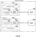
- FIG. 2 illustrates another embodiment in which the composite apparatus 10 is provided with a console display 106 for the MFP 100 and a console display 206 for the IT apparatus 200.
- This embodiment does not require the selector 30 or the switch processor 20, but users will be bothered by manipulating the MFP 10 and the IT apparatus 200 using the console displays 106 and 206 separately.
- the console displays 106 and 206 will occupy a large area of the surface of the composite apparatus 10, compromising the compactness of the composite apparatus 10. Even allowing for not requiring the selector 30 or the switch processor 20, the embodiment of FIG. 2 is less advantageous.
- FIG. 3 illustrates an initial menu screen to be displayed on the console display 300 while the composite apparatus 10 is not in use (in the initial state).
- function buttons each corresponding to a user-accessible function of the IT apparatus 200 and the MFP 100 are shown.
- the "IT Functions” column in this screen listed are the function buttons titled “IT Function 1", “IT Function 2", “IT Function 3", and “IT Function 4"; and these function buttons belong to a function button group 210 for using the functions of the IT apparatus 200.
- MFP Functions In the "MFP Functions” column, listed are the function buttons titled “MFP Function 1 (Copy)", “MFP Function 2 (Scan)”, “MFP Function 3 (Facsimile)", and “MFP Function 4 (Box)”; and these function buttons belong to a function button group 110 for using the following functions of the MFP 100: copier function, scanner function, facsimile function, and box function.
- Box function is a function that uses a memory area called “box”, for example: the function of storing a scanned document in a box and the function of transferring a document from the box to outside.
- the user can access any of these functions of the IT apparatus 200 and the MFP 100 by touching the corresponding function button.
- the corresponding operation button may be shown both in the "MFP Functions" column and the "IT Functions” column in the initial menu screen.
- one operation button 310 corresponding to the common function may be shown in the screen.
- the order of priority on the cause for use is set in advance; when the user touches this one operation button 310, the switch processor 20 makes the selector 30 select either the IT apparatus 200 or the MFP 100 having the cause for use with a higher priority such that the drawing processor 203 or 103 is connected to the console display 300.
- the MFP 100 or the IP apparatus 200 is specified as the default apparatus for creating a PDF file. In other words, either of them is specified as the default apparatus to be connected to the console display 300 while the composite apparatus 10 is not in use.
- the switch processor 20 thus makes the selector 30 select either the MFP 100 or the IT apparatus 200 specified as the default apparatus such that the drawing processor 103 or 203 is connected to the console display 300.
- the drawing processor 203 of the IP apparatus 200 is connected to the console display 300 in accordance with the default settings. That is, when the user finishes the MFP 100, the switch processor 20 makes the selector 30 connect the drawing processor 203 of the IP apparatus 200 to the console display 300.
- the system processor 202 of the IT apparatus 200 transmits a notification of the user event to the system processor 102 of the MFP 100 through the switch processor 20.
- the drawing processor 103 of the MFP 100 then creates display data i.e. a screen corresponding to the touched button and stores the same on the display memory 105;
- FIG. 4 illustrates an MFP copy settings screen that is created and stored in this example.
- the system processor 102 transmits a connection request to the switch processor 20.
- the switch processor 20 makes the selector 30 connect the drawing processor 103 of the MFP 100 to the console display 300.
- the drawing processor 103 of the MFP 100 then transfers the display data from the display memory 105 to the console display 300, making the console display 300 show the MFP copy settings screen of FIG. 4 .
- a button 112 titled "Switch to IT Function Menu” is shown as well as the settings button titled “Paper Settings”, “Enlarge/Reduce”, “Number of Cop ies” , “Finish Settings”, and “Color/Monochrome”.
- the button 112 titled “Switch to IT Function Menu” is a button for switching the screen to an IT function menu screen as illustrated in FIG. 5 ; and it is always shown when a screen of the MFP 100 is displayed on the console display 300. Simply by pressing the button 112 titled "Switch to IT Function Menu", the user can go to the IT function menu screen to access a function of the IT apparatus 200 even while manipulating the MFP 100.
- the user can start copy by the MFP 100 by pressing a Start button that is not shown in the figure.
- the composite apparatus 10 returns to the initial state.
- the system processor 102 of the MFP 100 transmits a notification of the completion of the process to the system processor 202 of the IT apparatus 200 through the switch processor 20.
- the drawing processor 203 of the IT apparatus 200 then creates display data i.e. an initial menu screen and stores the same on the display memory 205.
- the switch processor 20 makes the selector 30 connect the drawing processor 203 of the IT apparatus 200 to the console display 300; and the drawing processor 203 of the IT apparatus 200 makes the console display 300 show the initial menu screen of FIG. 3 .
- the system processor 102 of the MFP 100 transmits a notification of the user event to the system processor 202 of the IT apparatus 200 through the switch processor 20.
- the drawing processor 203 of the IT apparatus 200 creates display data i.e. the IT function menu screen of FIG. 5 and stores the same on the display memory 205.
- the system processor 202 of the IT apparatus 200 transmits a connection request to the switch processor 20; receiving this request, the switch processor 20 makes the selector 30 connect the drawing processor 203 of the IT apparatus 200 to the console display 300.
- the drawing processor 203 of the IT apparatus 200 then makes the console display 300 show the IT function menu screen of FIG. 5 .
- a button 212 titled “Switch to MFP Function Menu” is shown as well as the function buttons titled “IT Function 1", “IT Function 2", “IT Function 3", and "IT Function 4".
- the button 212 titled “Switch to MFP Function Menu” is a button for switching the screen to an MFP function menu screen as illustrated in FIG. 6 ; and it is always shown when a screen of the IT apparatus 200 is displayed on the console display 300. Simply by pressing the button 212 titled "Switch to MFP Function Menu", the user can go to the MFP function menu screen to access a function of the MFP 100 even while manipulating the IT apparatus 200.
- the user can select any of the function buttons in the IT function menu screen, configure various settings from the screen, and start the function.
- the drawing processor 203 creates display data i.e. the initial menu screen of FIG. 3 and makes the console display 300 show the initial menu screen.
- the selector 30 does not work at this time since the drawing processor 203 of the IT apparatus 200 is already connected to the console display 300.
- the system processor 202 of the IT apparatus 200 transmits a notification of the user event to the system processor 102 of the MFP 100 through the switch processor 20.
- the drawing processor 103 of the MFP 100 creates display data i.e. the MFP function menu screen of FIG. 6 and stores the same on the display memory 105.
- the system processor 102 of the MFP 100 transmits a connection request to the switch processor 20; receiving this request, the switch processor 20 makes the selector 30 connect the drawing processor 103 of the MFP 100 to the console display 300.
- the drawing processor 103 of the MFP 100 then makes the console display 300 show the MFP function menu screen of FIG. 6 .
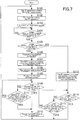
- FIG. 7 is a flowchart representing the basic operation of the composite apparatus 10.
- Step S101 the drawing processor 203 of the IT apparatus 200 creates display data i.e. the initial menu screen of FIG. 3 and stores the display data on the display memory (VRAM) 205.
- Step S102 the switch processor 20 makes the selector 30 select the IT apparatus 200 in accordance with the default settings such that the drawing processor 203 of the IP apparatus 200 is connected to the console display 300.
- Step S103 the drawing processor 203 of the IT apparatus 200 makes the console display 300 show the display data stored on the display memory 205, which is the initial menu screen.
- Step S104 it is judged whether or not a user event occurs to the touch panel of the console display 300. If no user event occurs (NO in Step S104), the routine waits until a user event occurs. If a user event occurs (YES in Step S104), it is further judged in Step S105 whether or not a function of the MFP 100 is selected. If a function of the MFP 100 is selected (YES in Step S105), the routine proceeds to Step S106 in which the system processor 202 of the IT apparatus 200 transmits a notification of the selection to the system processor 102 of the MFP 100 through the switch processor 20. Receiving this notification, in Step S107, the system processor 102 of the MFP 100 makes the drawing processor 103 create a function settings screen for the selected function and transmits a connection request to the switch processor 20.
- Step S108 the switch processor 20 makes the selector 30 connect the drawing processor 103 of the MFP 100 to the console display 300.
- the drawing processor 103 of the MFP 100 makes the console display 300 show the function settings screen.
- Step S110 it is judged by the system processor 102 of the MFP 100 whether or not the selected function is finished. Specifically, the judgment whether or not the selected function is finished depends on the user response from a confirmation screen asking the user if he/she really hopes to finish the MFP 100 as illustrated in FIG. 8 . It will be judged that the function is finished if the user presses a YES button 113 (an instruction for disconnection); it will be judged that the function is not finished if the user presses a NO button 114.
- Step S110 if the selected function is finished (YES in Step S110), the routine proceeds to Step S112. If the selected function is not finished (NO in Step S110), the routine proceed to Step Sill in which it is judged by the system processor 102 of the MFP 100 whether or not a predetermined period of time has elapsed with no user event to the console display 300 or other event to the MFP 100. If a predetermined period of time has not elapsed (NO in Step S111), the routine returns to Step S110. If a predetermined period of time has elapsed (YES in Step S111), the routine proceeds to Step S112.
- Step S112 the system processor 102 of the MFP 100 transmits a notification to the system processor 202 of the IT apparatus 200 through the switch processor 20; and it is a notification that notifies of the finish of the function or notifies of no user event or other event to the MFP 100 for a predetermined period of time.
- the routine then returns to Step S101.
- the switch processor 20 makes the selector 30 connect the drawing processor 203 of the IT apparatus 200 to the console display 300, and the drawing processor 203 makes the console display 300 show the initial menu screen. If it is a notification that notifies of no user event and no change in the operational state of the MFP 100 for a predetermined period of time, the switch processor 20 discards the connection request from the MFP 100 before the selective connection of the selector 30.
- the selector 30 connects the drawing processor 103 of the MFP 100 to the console display 300, the connection request from the MFP 100 is discarded, and the selector 30 connects the drawing processor 203 of the IT apparatus 200 specified as the default apparatus to the console display 300.
- the selector 30 connects the drawing processor 203 of the IT apparatus 200 specified as the default apparatus to the console display 300. So, the next user will not have to be bothered by switching the display screen of the console display 300 to the initial menu screen.
- Step S105 if a function of the MFP 100 is not selected (NO in Step S105), this means a function of the IT apparatus 200 is selected. So, in Step S113, the drawing processor 203 of the IT apparatus 200 creates a function settings screen for the selected function and makes the console display 300 show the screen. After that, in Step S114, it is judged by the system processor 202 whether or not the selected function is finished. If it is finished (YES in Step S114), the routine returns to Step S101. If the selected function is not finished (NO in Step S114), the routine proceed to Step S115 in which it is judged by the system processor 202 of the IT apparatus 200 whether or not a predetermined period of time has elapsed with no user event or other event to the IT apparatus 200. If a predetermined period of time has not elapsed (NO in Step S115), the routine returns to Step S114. If a predetermined period of time has elapsed (YES in Step S115), the routine returns to Step S101.
- the drawing processor 103 of the MFP 100 and the drawing processor 203 of the IT apparatus 200 create display data for the console display 300, separately.
- the switch processor 20 makes the selector 30 connect the drawing processor 103 or 203 depending on which apparatus should be used. This allows this one console display 300 to show screens of both the MFP 100 and the IT apparatus 200.
- FIG. 9 relates to the composite apparatus 10 of FIG. 1 , illustrating an explanatory chart on the timing at which the MFP 100 and the IT apparatus 200 create display data.
- the horizontal axis of the charts of FIG. 9 represents a temporal axis.
- the chart titled “MFP VRAM” indicates the timing at which display data is stored on the display memory 105 of the MFP 100; the chart titled “IT Apparatus VRAM” indicates the timing at which display data is stored on the display memory 205 of the IT apparatus 200.
- the chart titled “Display Data” indicates the timing at which the console display 300 shows the display data.
- the chart titled “Connection Request from MFP” indicates the timing at which the MFP 100 issues a connection request; the chart titled “Connection Request from IT apparatus” indicates the timing at which the IT apparatus 200 issues a connection request.
- the drawing processor 103 of the MFP 100 creates display data i.e. the MFP function menu screen A of FIG. 6 as the initial screen of the MFP 100 and stores the display data on the display memory 105; meanwhile, the drawing processor 203 of the IT apparatus 200 creates display data i.e. the initial menu screen D of FIG. 3 and stores the display data on the display memory 205.
- the selector 30 connects the drawing processor 203 of the IP apparatus 200 to the console display 300 in accordance with the default settings, and thus the console display 300 shows the initial menu screen D of FIG. 3 .
- a function button on the console display 300 corresponding to a function of the MFP 100, is touched.
- the MFP 100 then creates display data i.e. an operation screen B specified by the function (for example, the MFP copy settings screen of FIG. 4 ) and stores the display data on the display memory 105. Subsequently, the MFP 100 transmits a connection request to the switch processor 20.
- the switch processor 20 makes the selector 30 connect the drawing processor 103 of the MFP 100 to the console display 300, and thus the console display 300 shows the operation screen B.
- the IT apparatus 200 receives data externally.
- the drawing processor 203 of the IT apparatus 200 then creates display data i.e. a data reception notifying screen E and stores the display data on the display memory 205.
- the system processor 202 transmits a connection request to the switch processor 20.
- the selector 30 selects either of them in accordance with the order of priority on the cause for connection request which is set in advance.
- external data reception is given a higher priority than a user event to an operation screen; in accordance with the order of priority, the switch processor 20 makes the selector 30 continuously select the MFP 100, and thus the console display 300 continuously shows the operation screen B of the MFP 100.
- the order of priority on the cause for connection request is set in advance.
- the switch processor 20 makes the selector 30 select either the MFP 100 or the IT apparatus 200 having issued the connection request including the cause for connection request with a higher priority such that the drawing processor 103 or 203 is connected to the console display 300. That is, the switch processor 20 controls the selective connection appropriately even in the case of a conflict between connection requests from the MFP 100 and the IT apparatus 200.
- the IT apparatus 200 finishes the data receiving process.
- the IT apparatus 200 then withdraws the connection request to the switch processor 20 and creates display data i.e. the initial menu screen D.
- the selector 30 connects the drawing processor 203 of the IP apparatus 200 to the console display 300 in accordance with the default settings, and thus the console display 300 shows the initial menu screen D.
- the MFP 100 receives data externally.
- the drawing processor 103 of the MFP 100 then creates display data i.e. a data reception notifying screen C and stores the display data on the display memory 105.
- the system processor 102 transmits a connection request to the switch processor 20.
- the switch processor 20 makes the selector 30 select the MFP 100, and thus the console display 300 displays the data reception notifying screen C.
- FIG. 10 relates to the composite apparatus 10 of FIG. 1 , illustrating another example of the explanatory chart on the timing at which the MFP 100 and the IT apparatus 200 create display data.
- the user uses the function of the MFP 100 from Time T4 to Time T10.
- the function of the MFP 100 is finished at Time T6.
- the selector 30 selects the IT apparatus 200, and thus the console display 300 shows the data reception notifying screen E that is generated by the IT apparatus 200.
- the function of the MFP 100 is used until Time T10 in the example of FIG. 10 .
- the selector 30 continuously connects the drawing processor 103 of the MFP 100 to the console display 300, and thus the console display 300 continuously shows the operation screen B of the MFP 100.
- the IT apparatus 200 finishes the data receiving process.
- the system processor 202 of the IT apparatus 200 then withdraws the connection request, and the drawing processor 203 creates display data i.e. the initial menu screen D. Meanwhile, the function of the MFP 100 is still being used, and the connection request from the MFP 100 is still valid accordingly.
- the selector 30 continuously connects the drawing processor 103 of the MFP 100 to the console display 300, and thus the console display 300 continuously shows the operation screen B of the MFP 100.
- the IT apparatus 200 again receives data externally.
- the drawing processor 203 of the IT apparatus 200 then creates display data i.e. the data reception notifying screen E.
- the system processor 202 transmits a connection request to the switch processor 20.
- the function of the MFP 100 is still being used, and the connection request from the MFP 100 is still valid accordingly.
- the selector 30 continuously connects the drawing processor 103 of the MFP 100 to the console display 300, and thus the console display 300 continuously shows the operation screen B of the MFP 100.
- the function of the MFP 100 is finished.
- the system processor 102 of the MFP 100 then withdraws the connection request, and the drawing processor 103 creates display data i.e. the MFP function menu screen A.
- the switch processor 20 still has the connection request from the system processor 202 of the IT apparatus 200. So, at Time T10, the switch processor 20 makes the selector 30 select the IT apparatus 200, and thus the console display 300 shows a screen F of the IT apparatus 200.
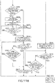
- FIG. 11A and FIG. 11B are flowcharts representing another example of the operation of the composite apparatus 10 of FIG. 1 .
- another event than a user event to the console display 300 occurs to the MFP 100 before the user selects a function button in the initial menu screen, corresponding to a function of the MFP 100.
- Step S201 the drawing processor 203 of the IT apparatus 200 creates display data i.e. the initial menu screen and stores the display data on the display memory (VRAM) 205.
- Step S202 the switch processor 20 makes the selector 30 select the IT apparatus 200 in accordance with the default settings such that the drawing processor 203 of the IP apparatus 200 is connected to the console display 300.
- Step S203 the drawing processor 203 of the IT apparatus 200 makes the console display 300 show the display data stored on the display memory 205, which is the initial menu screen.
- Step S204 it is judged by the system processor 102 of the MFP 100 whether or not another event than a user event to the console display 300 occurs.
- the system processor 102 of the MFP 100 can detect another event than a user event to the console display 300.
- the MFP 100 can detect by a paper feed sensor that a document is set on an automatic document feeder, the MFP 100 can detect by a cover state sensor that a document cover is opened or closed, the MFP 100 can detect by a cassette state sensor that a paper feed cassette is opened or closed, and the MFP 100 can detect by a component state sensor that any other component cover is opened or closed.
- the MFP 100 may be provided with an external data input portion for externally receiving data through a facsimile circuit and/or a network circuit; in this case, the MFP 100 can detect by the external data input portion that facsimile data and/or print data is received externally.
- the MFP 100 may be provided with a connector for interfacing with a portable terminal apparatus such as a smartphone or a tablet computer; in this case, the MFP 100 can detect by the connector that the MFP 100 successfully interfaces with the terminal apparatus.
- the MFP 100 may be provided with an error sensor for detecting job errors such as a paper jam and a toner empty; in this case, the MFP 100 can detect a job error by the error sensor.
- the MFP 100 may be provided with a maintenance mode switch for switching the MFP 100 to maintenance mode; in this case, the MFP 100 can detect by the maintenance mode switch that the MFP 100 enters maintenance mode.
- Step S204 another event than a user event to the console display 300 occurs (YES in Step S204), the routine proceeds to Step S205 in which the drawing processor 103 of the MFP 100 creates display data i.e. a screen corresponding to the event that occurred and updates the image (display data) stored on the display memory 105. The routine then proceeds to Step S206. If another event than a user event to the console display 300 does not occur (NO in Step S204), the routine proceeds directly to Step S206.
- Step S206 it is judged whether or not a user event occurs to the touch panel of the console display 300. If no user event occurs (NO in Step S206), the routine returns to Step S204. If a user event occurs (YES in Step S206), it is further judged in Step S207 whether or not a function of the MFP 100 is selected. If a function of the MFP 100 is selected (YES in Step S207), the routine proceeds to Step S208 in which the system processor 202 of the IT apparatus 200 transmits a notification of the selection to the system processor 102 of the MFP 100 through the switch processor 20. In Step S209, upon the reception of this notification, it is judged by the system processor 102 of the MFP 100 whether or not the display data stored on the display memory 102 has been updated.
- Step S209 the routine proceeds to Step S210 in which the system processor 102 of the MFP 100 transmits a connection request to the switch processor 20, and the switch processor 20 makes the selector 30 connect the drawing processor 103 of the MFP 100 to the console display 300.
- Step S211 the switch processor 20 makes the console display 300 show the up-to-date display data stored on the display memory 105. For example, if a facsimile has been received completely, the console display 300 shows a message that notifies of the reception of the facsimile, as illustrated in FIG. 12 . As well as the message, it also shows an OK button 115.
- Step S212 it is further judged whether or not the OK button 115 in the screen of FIG. 12 is pressed. If the OK button 115 is not pressed (NO in Step S212), the routine waits until it is pressed. If the OK button 115 is pressed (YES in Step S212), the routine proceeds to Step S214.
- Step S209 If the display data stored on the display memory 105 has not been updated (NO in Step S209), the routine proceeds to Step S213 in which the system processor 102 of the MFP 100 transmits a connection request to the switch processor 20, and the switch processor 20 makes the selector 30 connect the drawing processor 103 of the MFP 100 to the console display 300. The routine then proceeds to Step S214.
- Step S214 the drawing processor 103 of the MFP 100 creates display data i.e. the function settings screen and makes the console display 300 show the display data.
- Step S215 it is judged by the system processor 102 of the MFP 100 whether or not the selected function is finished. If the selected function is finished (YES in Step S215), the routine proceeds to Step S217. If the selected function is not finished (NO in Step S215), the routine proceed to Step S216 in which it is judged by the system processor 102 of the MFP 100 whether or not a predetermined period of time has elapsed with no user event or other event to the MFP 100. If a predetermined period of time has not elapsed (NO in Step S216), the routine returns to Step S215. If a predetermined period of time has elapsed (YES in Step S216), the routine proceeds to Step S217.
- Step S217 the system processor 102 of the MFP 100 transmits a notification to the system processor 202 of the IT apparatus 200 through the switch processor 20; and it is a notification that notifies of no user event or other event to the MFP 100 for a predetermined period of time.
- the routine then returns to Step S201.
- the switch processor 20 makes the selector 30 connect the drawing processor 203 of the IT apparatus 200 to the console display 300; and the drawing processor 203 makes the console display 300 show the initial menu screen.
- Step S207 if a function of the MFP 100 is not selected (NO in Step S207), this means a function of the IT apparatus 200 is selected. So, in Step S218, the drawing processor 203 of the IT apparatus 200 creates a function settings screen for the selected function and makes the console display 300 show the screen. After that, in Step S219, it is judged by the system processor 202 of the IT apparatus 200 whether or not the selected function is finished. If it is finished (YES in Step S219), the routine returns to Step S201.
- Step S220 the routine proceed to Step S220 in which it is judged by the system processor 202 whether or not a predetermined period of time has elapsed with no user event or other event to the IT apparatus 200. If a predetermined period of time has not elapsed (NO in Step S220), the routine returns to Step S219. If a predetermined period of time has elapsed (YES in Step S220), the routine returns to Step S201.
- the MFP 100 updates the display data stored on the display memory 105 in sync with an event that occurs to the MFP 100 itself.
- the drawing processor 103 makes the console display 300 show the up-to-date display data stored on the display memory 105. This allows the user to know the event that most recently occurred to the MFP 100.
- the MFP 100 may retain the display data stored on the display memory 105 without updating the display data in sync with an event that occurs to the MFP 100 itself.
- the drawing processor 103 makes the console display 300 show the display data stored on the display memory 105, which has been retained.
- the user may select a function of the MFP 100 via the initial menu screen of FIG. 3 displayed on the console display 300, which allows the user to select from the functions of the MFP 100 and the IT apparatus 200 that constitute the composite apparatus 10; in this case, while the selector 30 selects the MFP 100, the drawing processor 203 of the IT apparatus 200 preferably does not retain the initial menu screen of FIG. 3 stored on the display memory 205 but updates the display data with the screen of FIG. 5 to be displayed when the user presses the button 112 titled "Switch to IT Function Menu" in the MFP function menu screen. That is because a screen of the IT apparatus 200 next will be displayed most likely when the user presses the button 112 titled "Switch to IT Function Menu" in the MFP function menu screen of FIG. 4 .
- the display data stored on the display memory 205 of the IT apparatus 200 may be an instant display screen such as a screen notifying that data is being received; in this case, while the selector 30 selects the MFP 100, the drawing processor 203 of the IT apparatus 200 may retain, instead of the instant display screen stored on the display memory 205, the display data having been stored thereon prior to the instant display screen.
- the display data stored on the display memory 105 of the MFP 100 may be an instant display screen; in this case, while the selector 30 selects the IT apparatus 200, the drawing processor 103 of the MFP 100 may retain, instead of the instant display screen stored on the display memory 105, the display data having been stored thereon prior to the instant display screen.
- FIG. 13 is a block diagram illustrating the configuration of a composite apparatus 10 according to yet another embodiment of the present invention. It is preferred that this composite apparatus 10 have this configuration in case that the MFP 100 and/or the IT apparatus 200 are/is incapable of creating display data in the same resolution as that of a console display 300.
- a drawing processor 103 of the MFP 100 is provided with a resolution adjuster 106 such that, if necessary, the drawing processor 103 makes the resolution adjuster 106 adjust the resolution of the display data 104 before storing it on a display memory 105.
- a drawing processor 203 of the IT apparatus 200 it is also provided with a resolution adjuster 206 such that, if necessary, the drawing processor 203 makes the resolution adjuster 206 adjust the resolution of the display data 204 before storing it on a display memory 205.
- the configuration of the MFP 100, excluding the resolution adjuster 106 is identical with that in FIG. 1 and the configuration of the IT apparatus 200, excluding the resolution adjuster 206, is identical with that in FIG 1 . While identical elements in this figure are given the same codes as those in FIG. 1 , a detailed description of them will be omitted.
- the MFP 100 and the IT apparatus 200 need to create display data in the same resolution as that of the console display 300.
- the MFP 100 and the IT apparatus 200 each are capable of operating independently, the MFP 100 and the IT apparatus 20 may be incapable of creating display data in the same resolution as that of the console display 300.
- the MFP 100 and the IT apparatus 200 that constitute the composite apparatus 10 may be readily available and common ones; in this case, it is highly likely that the MFP 100 and the IT apparatus 200 are incapable of creating display data in the same resolution as that of the console display 300 because the MFP 100 and the IT apparatus 200 are configured to create display data in resolutions that match the resolutions of their own console displays.
- the MFP 100 is incapable of creating display data in the same resolution as that of the console display 300, it is necessary that the MFP 100 adjust the resolution of the display data 104 before storing it on the display memory 105; similarly, if the IT apparatus 200 is incapable of creating display data in the same resolution as that of the console display 300, it is necessary that the IT apparatus 200 adjust the resolution of the display data 204 before storing it on the display memory 205.
- the resolution adjusters 106 and 206 are set in the MFP 100 and the IT apparatus 200, respectively, such that the MFP 100 adjusts the resolution of the display data 104 by the resolution adjuster 106 before storing it on the display memory 105 and the IT apparatus 200 adjusts the resolution of the display data 204 by the resolution adjuster 206 before storing it on the display memory 205.
- FIG. 14 is an explanatory view on the overview of a resolution adjustment process.
- the console display 300 of the composite apparatus 10 has a resolution of 1366 x 768 dots
- the resolution of the display data 104 to be stored on the MFP 100 is 1366 x 768 dots, being exactly the same as that of the console display 300.
- the drawing processor 103 of the MFP 100 thus stores the display data 104 on the display memory 105 without adjusting the resolution, and makes the console display 300 show the display data 104.
- the resolution of the display data 204 to be stored on the IT apparatus 200 is 800 x 480 dots.
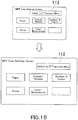
- the drawing processor 203 of the IT apparatus 200 thus makes the resolution adjuster 206 adjust the resolution to 1366 x 768 dots, and stores the display data 204 in this adjusted resolution, and then makes the console display 300 show the display data 204. This will be an enlarged screen as illustrated in FIG. 15 .
- the MFP 100 adjusts the resolution of display data to that of the console display 300 by the resolution adjuster 106; similarly, if the resolution of the IT apparatus 200 is different from that of the console display 300, the IT apparatus 200 adjusts the resolution of display data to that of the console display 300 by the resolution adjuster 206. This allows the console display 300 to show display data always in an appropriate resolution.
Landscapes
- Engineering & Computer Science (AREA)
- Multimedia (AREA)
- Signal Processing (AREA)
- Human Computer Interaction (AREA)
- General Engineering & Computer Science (AREA)
- Theoretical Computer Science (AREA)
- Computing Systems (AREA)
- Physics & Mathematics (AREA)
- General Physics & Mathematics (AREA)
- Facsimiles In General (AREA)
- Control Or Security For Electrophotography (AREA)
- User Interface Of Digital Computer (AREA)
- Accessory Devices And Overall Control Thereof (AREA)
Abstract
Description
- The present invention relates to a composite apparatus that is provided with multiple apparatuses each being capable of operating independently, for example: an image forming apparatus such as a multi-function peripheral (MFP), i.e., a multifunctional digital machine; and an information processing apparatus such as a personal computer (PC).
- It is common that, in addition to MFPs mainly for copying and printing, many information processing apparatuses for electronic data processing, such as servers, are also used in workplaces; it is also common that such an information processing apparatus and such an MFP are used together for composite processing.
- To reduce the cost of the management and maintenance of apparatuses in an entire workplace, there is a suggestion to build one composite apparatus by consolidating multiple apparatuses each that are capable of operating independently, such as an image processing apparatus and an MFP, into one cabinet.
- Since these apparatuses constituting one composite apparatus each are capable of operating independently, each of them can be, unsurprisingly, provided with its own console display means for a user to manipulate the apparatus, such as an operational panel that displays various types of display data such as operation screens.
- One composite apparatus with multiple console display means, however, will never be useful for users. Furthermore, the multiple console display means, which are open to the outside of the composite apparatus, will occupy a large area of the surface of the composite apparatus, compromising the advantages of one composite apparatus that is constituted by multiple apparatuses.
- Japanese Unexamined Patent Application Publication No.
2014-241494 - However, according to Japanese Unexamined Patent Application Publication No.
2014-241494 - So, the technique described in Japanese Unexamined Patent Application Publication No.
2014-241494 - The present invention, which has been made in consideration of such a technical background as described above, provides one composite apparatus including: multiple apparatuses each being capable of operating independently; and one console display means for a user to manipulate these apparatuses.
- The above-described problem can be solved by the following means.
- 1. A composite apparatus including:
- a first apparatus and a second apparatus each being capable of operating independently; and
- a console display means being shared by the first apparatus and the second apparatus, the first apparatus and the second apparatus each including:
- a display memory that stores display data to be displayed on the console display means; and
- a drawing processing means that makes the console display means show the display data stored on the display memory,
the composite apparatus further including:- a selector that selectively connects the drawing processing means of the first or second apparatus to the console display means; and
- a switch processing means that receives a connection request from the first or second apparatus, the connection request requesting to connect the drawing processing means of the first or second apparatus to the console display means and that makes the selector connect the drawing processing means of either the first or second apparatus to the console display means, the either one having issued the connection request,
- 2. The composite apparatus according to the
foregoing item 1, wherein:- the first or second apparatus is an image forming apparatus; and
- the switch processing means makes the selector connect the drawing processing means of the image forming apparatus to the console display means when a function of the image forming apparatus is selected via an operation screen displayed on the console display means, and makes the selector disconnect the drawing processing means of the image forming apparatus from the console display means when instructions to disconnect the drawing processing means of the image forming apparatus is given via an operation screen displayed on the console display means.
- 3. The composite apparatus according to the
foregoing item - a switch button that allows selecting the first or second apparatus to connect is shown in a screen on the console display means; and
- when the switch button is touched, the switch processing means makes the selector connect the drawing processing means of either the first or second apparatus to the console display means, the either one having issued the connection request.
- 4. The composite apparatus according to any one of the foregoing
items 1 to 3, wherein:- while the selector selects the first apparatus, the drawing processing means of the second apparatus updates the display data stored on the display memory in sync with an event occurring to the second apparatus; and
- after that, when the selector selects the second apparatus, the drawing processing means of the second apparatus makes the console display means show the display data stored on the display memory, the display data being updated.
- 5. The composite apparatus according to the
foregoing item 4, wherein:- the first or second apparatus is an image forming apparatus; and
- the drawing processing means of the image forming apparatus updates the display data in sync with an event occurring to a part of the image forming apparatus, the part being other than the console display means.
- 6. The composite apparatus according to the
foregoing item 4, wherein:- the first or second apparatus is an image forming apparatus, the image forming apparatus comprising a data input means that is capable of externally receiving data from both or either of a facsimile circuit and a network circuit; and
- the drawing processing means of the image forming apparatus updates the display data when the data input means externally receives data.
- 7. The composite apparatus according to the
foregoing item 4, wherein:- the first or second apparatus is an image forming apparatus, the image forming apparatus comprising an interfacing means that is capable of interfacing with a portable terminal apparatus; and
- the drawing processing means of the image forming apparatus updates the display data when the interfacing means successfully interfaces with the portable terminal apparatus.
- 8. The composite apparatus according to the
foregoing item 4, wherein:- the first or second apparatus is an image forming apparatus, the image forming apparatus comprising an error sensing means that detects a job error; and
- the drawing processing means of the image forming apparatus updates the display data when the error sensing means detects a job error.
- 9. The composite apparatus according to the
foregoing item 4, wherein:- the first or second apparatus is an image forming apparatus, the image forming apparatus being capable of entering maintenance mode; and
- the drawing processing means of the image forming apparatus updates the display data when the image forming apparatus enters maintenance mode.
- 10. The composite apparatus according to any one of the foregoing
items 1 to 3, wherein, while the selector selects the first apparatus, the drawing processing means of the second apparatus retains the display data stored on the display memory. - 11. The composite apparatus according to any one of the foregoing
items 1 to 10, wherein:- the order of priority on the cause for connection request is set in advance; and
- when connection requests from the first apparatus and the second apparatus are conflicting, each connection request including the cause for connection request, the switch processing means makes the selector connect the drawing processing means of either the first or second apparatus to the console display means, the either one having issued the connection request including the cause of connection request with a higher priority.
- 12. The composite apparatus according to any one of the foregoing
items 1 to 3, wherein :- when the selector selects the first apparatus, the display data stored on the display memory of the second apparatus is an initial menu screen, the initial menu screen allowing selecting from the functions of the first apparatus and the second apparatus; and
- while the selector selects the first apparatus, the drawing processing means of the second apparatus does not retain the initial menu screen stored on the display memory.
- 13. The composite apparatus according to the foregoing
item 10, wherein:- when the selector selects the first apparatus, the display data stored on the display memory of the second apparatus is an instant display screen; and
- while the selector selects the first apparatus, the drawing processing means of the second apparatus retains, instead of the instant display screen stored on the display memory, the display data having been stored thereon prior to the instant display screen.
- 14. The composite apparatus according to any one of the foregoing
items 1 to 13, wherein, if a predetermined period of time has elapsed with no user event to the console display means or other event to either the first or second apparatus having issued the connection request, after the selector makes the drawing processing means of the either one connect to the console display means, the switch processing means makes the drawing processing means of the either one disconnect from the console display means and makes the selector connect the drawing processing means of either the first or second apparatus to the console display means, the either one being specified as the default apparatus. - 15. The composite apparatus according to any one of the foregoing
items 1 to 14, wherein, if the function of either the first or second apparatus having issued the connection request is finished after the selector makes the drawing processing means of the either one connect to the console display means, the selector makes the drawing processing means of either the first or second apparatus connect to the console display means, the either one being specified as the default apparatus. - 16. The composite apparatus according to any one of the foregoing
items 1 to 15, wherein:- the first apparatus and the second apparatus each comprise a resolution adjusting means that adjusts the resolution of the display data; and
- if the resolution of either the first or second apparatus selected by the selector is different from that of the console display means, the resolution adjusting means of the either one adjusts the resolution of the display data to that of the console display means, and the drawing processing means of the either one makes the console display means show the display data in the adjusted resolution.
- 17. The composite apparatus according to any one of the foregoing
items 1 to 16, wherein:- if the first apparatus and the second apparatus have a function in common, one function button corresponding to the common function is shown in an initial menu screen displayed on the console display means, the initial menu screen allowing selecting from the functions of the first apparatus and the second apparatus;
- the order of priority on the cause for use is set in advance; and
- when the one function button corresponding to the common function is touched, the switch processing means makes the selector connect the drawing processing means of either the first or second apparatus to the console display means, the either one having the cause for use with a higher priority.
- According to the invention described in the foregoing
item 1, a composite apparatus includes: a first apparatus and a second apparatus each that are capable of operating independently; and a console display means that is shared by the first apparatus and the second apparatus. The first apparatus and the second apparatus each include: a display memory that stores display data to be displayed on the console display means; and a drawing processing means that makes the console display means show the display data. The composite apparatus further includes: a selector that selectively connects the drawing processing means of the first or second apparatus to the console display means; and a switch processing means that receives a connection request from the first or second apparatus, the connection request requesting to connect the drawing processing means of the first or second apparatus to the console display means, and that makes the selector connect the drawing processing means of either the first or second apparatus having issued the connection request to the console display means. That is, while the drawing processing means of the first or second apparatus creates display data to be displayed on the console display means, the selector connects the drawing processing means of either the first or second apparatus to be used to the console display means. The one console display means is thus allowed to display operation screens of the first apparatus and the second apparatus alternately. - The composite apparatus with the one console display means shared by the first apparatus and the second apparatus is sufficient accordingly, eliminating the need for one console display means for each apparatus. This is useful for users because they do not have to find a console display means to manipulate their target apparatus and only need to find this one console display means to manipulate the composite apparatus. Furthermore, this one console display means never occupies a large area of the surface of the composite apparatus, retaining the compact body of the composite apparatus.
- According to the invention described in the foregoing
item 2, the first or second apparatus is an image forming apparatus. The drawing processing means of the image forming apparatus is connected to the console display means when a function of the image forming apparatus is selected via an operation screen displayed on the console display means, and the drawing processing means of the image forming apparatus is disconnected from the console display means when instructions to disconnect the drawing processing means of the image forming apparatus is given via an operation screen displayed on the console display means. This allows the user to manipulate the image forming apparatus using this one console display means in a similar manner to using the console display means owned by the image forming apparatus. - According to the invention described in the foregoing
item 3, a switch button that allows selecting the first or second apparatus to connect is shown in a screen on the console display means. When the switch button is touched, the drawing processing means of either the first or second apparatus having issued the connection request is connected to the console display means. This allows the user to use functions of the first apparatus and the second apparatus alternately, simply by touching the switch button. - According to the invention described in the foregoing
item 4, while the selector selects the first apparatus, the drawing processing means of the second apparatus updates the display data stored on the display memory in sync with an event occurring to the second apparatus. After that, when the selector selects the second apparatus, the drawing processing means of the second apparatus makes the console display means show the up-to-date display data stored on the display memory. This allows the user to know the event that most recently occurred to the second apparatus. - According to the invention described in the foregoing item 5, the image forming apparatus updates the display data in sync with an event occurring to a part of the image forming apparatus which is other than the console display means.
- According to the invention described in the foregoing item 6, the image forming apparatus updates the display data upon externally receiving data by a data input means that is capable of externally receiving data through both or either of a facsimile circuit and a network circuit.
- According to the invention described in the foregoing item 7, the image forming apparatus updates the display data upon successfully interfacing with a portable terminal apparatus.
- According to the invention described in the foregoing item 8, the image forming apparatus updates the display data upon detecting a job error.
- According to the invention described in the foregoing item 9, the image forming apparatus updates the display data upon entering maintenance mode.
- According to the invention described in the foregoing
item 10, while the selector selects the first apparatus, the drawing processing means of the second apparatus retains the display data stored on the display memory. After that, when the selector selects the second apparatus, the drawing processing means of the second apparatus makes the console display means show the display data retained on the display memory. - According to the invention described in the foregoing item 11, the order of priority on the cause for connection request is set in advance. When connection requests from the first apparatus and the second apparatus are conflicting, each connection request including the cause for connection request, the drawing processing means of either the first or second apparatus having issued the connection request including the cause for connection request with a higher priority is connected to the console display means. This contributes to a smooth connecting process even in the case of a conflict between connection requests from the first apparatus and the second apparatus.
- According to the invention described in the foregoing item 12, when the selector selects the first apparatus, the display data stored on the display memory of the second apparatus may be an initial menu screen, the initial menu screen allowing selecting from the functions of the first apparatus and the second apparatus. In this case, while the selector selects the first apparatus, the initial menu screen stored on the display memory is updated with other display data instead of being retained.
- According to the invention described in the foregoing item 13, when the selector selects the first apparatus, the display data stored on the display memory of the second apparatus may be an instant display screen. In this case, there is no need to retain the instant display screen and, instead of the instant display screen, the display data having been stored thereon prior to the instant display screen is retained while the selector selects the first apparatus.
- According to the invention described in the foregoing item 14, if a predetermined period of time has elapsed with no user event to the console display means or other event to either the first or second apparatus having issued the connection request, after the selector makes the drawing processing means of the first or second apparatus connect to the console display means, the connection request is discarded and the drawing processing means of the first or second apparatus specified as the default apparatus is connected to the console display means. So, the next user will not have to be bothered by switching the display screen of the console display means to the initial menu screen.
- According to the invention described in the foregoing item 15, if the function of either the first or second apparatus having issued the connection request is finished after the selector makes the drawing processing means of the first or second apparatus connect to the console display means, the drawing processing means of the first or second apparatus specified as the default apparatus is connected to the console display means. So, the next user will not have to be bothered by switching the display screen of the console display means to the initial menu screen.
- According to the invention described in the foregoing item 16, if the resolution of the first or second apparatus is different from that of the console display means, the resolution of the display data is adjusted to that of the console display means and the display data is shown on the console display means in the adjusted resolution. This allows the console display means to show display data always in an appropriate resolution.
- According to the invention described in the foregoing item 17, if the first apparatus and the second apparatus have a function in common, one function button corresponding to the common function is shown in an initial menu screen displayed on the console display means, the initial menu screen allowing selecting from the functions of the first apparatus and the second apparatus. The order of priority on the cause for use is set in advance; when the one function button corresponding to the common function is touched, the drawing processing means of either the first or second apparatus having the cause for use with a higher priority is connected to the console display means by the selector. This allows the user to use the common function without being confused by identical function buttons that correspond to the common function of the first apparatus and the second apparatus.
-
-
FIG. 1 is a block diagram illustrating the configuration of a composite apparatus according to one embodiment of the present invention; -
FIG. 2 is a block diagram illustrating the configuration of a composite apparatus according to another embodiment of the present invention for comparison; -
FIG. 3 illustrates an initial menu screen to be displayed on a console display means; -
FIG. 4 illustrates a screen to be displayed when the user presses a button titled "MFP Function 1 (Copy)" in the initial menu screen ofFIG. 3 ; -
FIG. 5 illustrates a screen to be displayed when the user presses a button titled "Switch to IT Function Menu" in the screen ofFIG. 4 ; -
FIG. 6 illustrates a screen to be displayed when the user presses a button titled "Switch to MFP Function Menu" in the screen ofFIG. 5 ; -
FIG. 7 is a flowchart representing the basic operation of the composite apparatus; -
FIG. 8 illustrates a confirmation screen asking the user if he/she really hopes to finish the MFP; -
FIG. 9 relates to the composite apparatus ofFIG. 1 , illustrating an explanatory chart on the timing at which a first apparatus and a second apparatus create display data; -
FIG. 10 relates to the composite apparatus ofFIG. 1 , illustrating another example of the explanatory chart on the timing at which the first apparatus and the second apparatus create display data; -
FIG. 11A andFIG. 11B are flowcharts representing another example of the operation of the composite apparatus ofFIG. 1 ; -
FIG. 12 illustrates a screen on the console display means, showing the up-to-date display data stored on a display memory; -
FIG. 13 is a block diagram illustrating the configuration of a composite apparatus according to yet another embodiment of the present invention; -
FIG. 14 is an explanatory view on the overview of a resolution adjustment process; and -
FIG. 15 illustrates an example of a screen subjected to the resolution adjustment process. - Hereinafter, one or more embodiments of the present invention will be described with reference to the drawings.
-
FIG. 1 is a block diagram illustrating the configuration of acomposite apparatus 10 according to one embodiment of the present invention. In this embodiment, animage forming apparatus 100 and aninformation processing apparatus 200, respectively, are constituted by an MFP and a PC each that are capable of operating independently. These are consolidated into one cabinet, constituting acomposite apparatus 10. Hereinafter, theimage forming apparatus 100 and theinformation processing apparatus 200 will also be referred to asMFP 100 andIT apparatus 200, respectively. Thecomposite apparatus 10 is not necessarily constituted by theMFP 100 and theIT apparatus 200 both that are loaded in one cabinet; thecomposite apparatus 10 may be constituted by theMFP 100 and theIT apparatus 200 that are simply positioned adjacent to each other. - The
composite apparatus 10 is provided with theMFP 100, theIT apparatus 200, and oneconsole display 300 that is shared by theMFP 100 and theIT apparatus 200. - To operate independently, the
MFP 100 is provided with asystem processor 102 and adrawing processor 103. Thesystem processor 102 controls theMFP 100 in a unified manner and is essentially provided with a CPU, a ROM, and a RAM that are not shown in the figure. Under the control of thesystem processor 102, theMFP 100 receives user events and executes its copier function, printer function, scanner function, and other functions. Furthermore, thesystem processor 102 makes theconsole display 300 show display data of theMFP 100 by transmitting a connection request to aswitch processor 20, which will be later described in detail. - The drawing
processor 103 is provided with adisplay memory 105 for storingdisplay data 104, which a memory referred to as VRAM. The drawingprocessor 103 makes theconsole display 300 show thedisplay data 104 stored on thedisplay memory 105 by transferring the same to theconsole display 300. The drawingprocessor 103 creates thedisplay data 104 by combining many display elements stored on theMFP 100, such as operation buttons and messages, and stores the same on thedisplay memory 105. The drawingprocessor 103 also updates the content of thedisplay memory 105 as the need arises. - Although the
MFP 100 is essentially provided with a scanner, an image former, a storage device such as a hard disk drive, and a communication interface for communicating external apparatuses, as well as thesystem processor 102 and thedrawing processor 103, these are omitted fromFIG. 1 . - Similarly, to operate independently, the
IT apparatus 200 is provided with asystem processor 202 and adrawing processor 203. Thesystem processor 202 controls theIT apparatus 200 in a unified manner and is essentially provided with a CPU, a ROM, and a RAM that are not shown in the figure. Under the control of thesystem processor 202, theIT apparatus 200 receives a user event and executes processing in accordance with the user event. Furthermore, thesystem processor 202 makes theconsole display 300 show display data of theIT apparatus 200 by transmitting a connection request to theswitch processor 20, which will be later described in detail. - The drawing
processor 203 is provided with adisplay memory 205 for storingdisplay data 204. The drawingprocessor 203 makes theconsole display 300 show thedisplay data 204 stored on thedisplay memory 205 by transferring the same to theconsole display 300. The drawingprocessor 203 creates thedisplay data 204 by combining many display elements stored on theIT apparatus 200, such as operation buttons and messages, and stores the same on thedisplay memory 205. The drawingprocessor 203 also updates the content of thedisplay memory 205 as the need arises. These control operations will be later described in detail. - Although the
IT apparatus 200 is essentially provided with a storage device such as a hard disk drive and a communication interface for communicating external apparatuses, as well as thesystem processor 202 and thedrawing processor 203, these are omitted fromFIG. 1 . - The
console display 300 is a display device constituted by a liquid-crystal display, for example, having a touch panel laminated on its surface. When the user touches a screen, theconsole display 300 transfers touch information representing the coordinates of the user event to theMFP 100 or theIT apparatus 200. TheMFP 100 or theIT apparatus 200 then executes processing in accordance with the coordinates and makes theconsole display 300 show display data stored on thedisplay memory 105 or thedisplay memory 205 by transferring the same to theconsole display 300. - In this embodiment, the
composite apparatus 10 is further provided with aselector 30 and theswitch processor 20, which allows theMFP 100 and theIT apparatus 200 to share this only oneconsole display 300. - The
selector 30 selectively connects thedrawing processor 103 of theMFP 100 or thedrawing processor 203 of theIT apparatus 200 to theconsole display 300. Specifically, when theselector 30 selectively connects thedrawing processor 103 of theMFP 100 to theconsole display 300, the drawingprocessor 103 makes theconsole display 300 show thedisplay data 104 stored on thedisplay memory 105 of theMFP 100 by transferring the same to theconsole display 300 through theselector 30. Subsequently, when the user touches an operation screen of theMFP 100 from theconsole display 300, theconsole display 300 transfers touch information to theMFP 100. When theselector 30 selectively connects thedrawing processor 203 of theIT apparatus 200 to theconsole display 300, the drawingprocessor 203 makes theconsole display 300 show thedisplay data 204 stored on thedisplay memory 205 of theIT apparatus 200 by transferring the same to theconsole display 300 through theselector 30. Subsequently, when the user touches an operation screen of theIT apparatus 200 from theconsole display 300, theconsole display 300 transfers touch information to theIT apparatus 200. - The
switch processor 20 controls the selective connection of theselector 30 depending on from which it receives a connection request, thesystem processor 102 of theMFP 100 or thesystem processor 202 of theIT apparatus 200. Specifically, when theswitch processor 20 receives a connection request from thesystem processor 102 of theMFP 100, theswitch processor 20 makes theselector 30 connect thedrawing processor 103 of theMFP 100 to theconsole display 300; when theswitch processor 20 receives a connection request from thesystem processor 202 of theIT apparatus 200, theswitch processor 20 makes theselector 30 connect thedrawing processor 203 of theIT apparatus 20 to theconsole display 300. - The
console display 300 is shared by theMFP 100 and theIT apparatus 200 in the above-mentioned manner. So, in this embodiment, thecomposite apparatus 10 with this oneconsole display 300 is sufficient and useful for users, eliminating the need for oneconsole display 300 for each apparatus; this oneconsole display 300 never occupies a large area of the surface of thecomposite apparatus 10, retaining the compact body of thecomposite apparatus 10. - In contrast,
FIG. 2 illustrates another embodiment in which thecomposite apparatus 10 is provided with aconsole display 106 for theMFP 100 and aconsole display 206 for theIT apparatus 200. This embodiment does not require theselector 30 or theswitch processor 20, but users will be bothered by manipulating theMFP 10 and theIT apparatus 200 using the console displays 106 and 206 separately. Furthermore, the console displays 106 and 206 will occupy a large area of the surface of thecomposite apparatus 10, compromising the compactness of thecomposite apparatus 10. Even allowing for not requiring theselector 30 or theswitch processor 20, the embodiment ofFIG. 2 is less advantageous. - Hereinafter, screens to be displayed on the
console display 300 will be described. -
FIG. 3 illustrates an initial menu screen to be displayed on theconsole display 300 while thecomposite apparatus 10 is not in use (in the initial state). In this initial menu screen, function buttons each corresponding to a user-accessible function of theIT apparatus 200 and theMFP 100 are shown. In the "IT Functions" column in this screen, listed are the function buttons titled "IT Function 1", "IT Function 2", "IT Function 3", and "IT Function 4"; and these function buttons belong to afunction button group 210 for using the functions of theIT apparatus 200. In the "MFP Functions" column, listed are the function buttons titled "MFP Function 1 (Copy)", "MFP Function 2 (Scan)", "MFP Function 3 (Facsimile)", and "MFP Function 4 (Box)"; and these function buttons belong to afunction button group 110 for using the following functions of the MFP 100: copier function, scanner function, facsimile function, and box function. Box function is a function that uses a memory area called "box", for example: the function of storing a scanned document in a box and the function of transferring a document from the box to outside. - The user can access any of these functions of the
IT apparatus 200 and theMFP 100 by touching the corresponding function button. - If the
IP apparatus 200 and theMFP 100 have a function in common, for example, the function of converting an image format file to PDF, the corresponding operation button may be shown both in the "MFP Functions" column and the "IT Functions" column in the initial menu screen. Alternatively, similar to theoperation button 310 titled "Convert to PDF" inFIG. 3 , oneoperation button 310 corresponding to the common function may be shown in the screen. In this case, the order of priority on the cause for use is set in advance; when the user touches this oneoperation button 310, theswitch processor 20 makes theselector 30 select either theIT apparatus 200 or theMFP 100 having the cause for use with a higher priority such that thedrawing processor console display 300. If the operation button corresponding to the common function is shown both in the "MFP Functions" column and the "IT Functions" column, the user will be confused about which to choose. In contrast, in this embodiment, the user does not have to be confused and can access the function simply by touching this oneoperation button 310. - As referred to the initial menu screen shown in
FIG. 3 , theMFP 100 or theIP apparatus 200 is specified as the default apparatus for creating a PDF file. In other words, either of them is specified as the default apparatus to be connected to theconsole display 300 while thecomposite apparatus 10 is not in use. Theswitch processor 20 thus makes theselector 30 select either theMFP 100 or theIT apparatus 200 specified as the default apparatus such that thedrawing processor console display 300. In this embodiment, while thecomposite apparatus 10 is not in use, the drawingprocessor 203 of theIP apparatus 200 is connected to theconsole display 300 in accordance with the default settings. That is, when the user finishes theMFP 100, theswitch processor 20 makes theselector 30 connect thedrawing processor 203 of theIP apparatus 200 to theconsole display 300. - Subsequently, when the user touches the
function button 111 titled "MFP Function 1 (Copy)", for example, in the initial menu screen ofFIG. 3 , thesystem processor 202 of theIT apparatus 200, for example, transmits a notification of the user event to thesystem processor 102 of theMFP 100 through theswitch processor 20. The drawingprocessor 103 of theMFP 100 then creates display data i.e. a screen corresponding to the touched button and stores the same on thedisplay memory 105;FIG. 4 illustrates an MFP copy settings screen that is created and stored in this example. After that, thesystem processor 102 transmits a connection request to theswitch processor 20. - Receiving a connection request from the
system processor 102 of theMFP 100, theswitch processor 20 makes theselector 30 connect thedrawing processor 103 of theMFP 100 to theconsole display 300. The drawingprocessor 103 of theMFP 100 then transfers the display data from thedisplay memory 105 to theconsole display 300, making theconsole display 300 show the MFP copy settings screen ofFIG. 4 . - In this MFP copy settings screen, a
button 112 titled "Switch to IT Function Menu" is shown as well as the settings button titled "Paper Settings", "Enlarge/Reduce", "Number of Copies", "Finish Settings", and "Color/Monochrome". Thebutton 112 titled "Switch to IT Function Menu" is a button for switching the screen to an IT function menu screen as illustrated inFIG. 5 ; and it is always shown when a screen of theMFP 100 is displayed on theconsole display 300. Simply by pressing thebutton 112 titled "Switch to IT Function Menu", the user can go to the IT function menu screen to access a function of theIT apparatus 200 even while manipulating theMFP 100. - After configuring various settings from the MFP copy settings screen, the user can start copy by the
MFP 100 by pressing a Start button that is not shown in the figure. Upon completion of the copy process, thecomposite apparatus 10 returns to the initial state. Specifically, thesystem processor 102 of theMFP 100 transmits a notification of the completion of the process to thesystem processor 202 of theIT apparatus 200 through theswitch processor 20. The drawingprocessor 203 of theIT apparatus 200 then creates display data i.e. an initial menu screen and stores the same on thedisplay memory 205. Theswitch processor 20 makes theselector 30 connect thedrawing processor 203 of theIT apparatus 200 to theconsole display 300; and thedrawing processor 203 of theIT apparatus 200 makes theconsole display 300 show the initial menu screen ofFIG. 3 . - Subsequently, when the user touches the
button 112 titled "Switch to IT Function Menu" in the MFP copy settings screen ofFIG. 4 , thesystem processor 102 of theMFP 100 transmits a notification of the user event to thesystem processor 202 of theIT apparatus 200 through theswitch processor 20. Receiving this notification, the drawingprocessor 203 of theIT apparatus 200 creates display data i.e. the IT function menu screen ofFIG. 5 and stores the same on thedisplay memory 205. After that, thesystem processor 202 of theIT apparatus 200 transmits a connection request to theswitch processor 20; receiving this request, theswitch processor 20 makes theselector 30 connect thedrawing processor 203 of theIT apparatus 200 to theconsole display 300. The drawingprocessor 203 of theIT apparatus 200 then makes theconsole display 300 show the IT function menu screen ofFIG. 5 . - In this IT function menu screen, a
button 212 titled "Switch to MFP Function Menu" is shown as well as the function buttons titled "IT Function 1", "IT Function 2", "IT Function 3", and "IT Function 4". Thebutton 212 titled "Switch to MFP Function Menu" is a button for switching the screen to an MFP function menu screen as illustrated inFIG. 6 ; and it is always shown when a screen of theIT apparatus 200 is displayed on theconsole display 300. Simply by pressing thebutton 212 titled "Switch to MFP Function Menu", the user can go to the MFP function menu screen to access a function of theMFP 100 even while manipulating theIT apparatus 200. - The user can select any of the function buttons in the IT function menu screen, configure various settings from the screen, and start the function. Upon the finish of the function, the drawing
processor 203 creates display data i.e. the initial menu screen ofFIG. 3 and makes theconsole display 300 show the initial menu screen. Theselector 30 does not work at this time since thedrawing processor 203 of theIT apparatus 200 is already connected to theconsole display 300. - Subsequently, when the user touches the
button 212 titled "Switch to MFP Function Menu" in the IT function menu screen, thesystem processor 202 of theIT apparatus 200 transmits a notification of the user event to thesystem processor 102 of theMFP 100 through theswitch processor 20. Receiving this notification, the drawingprocessor 103 of theMFP 100 creates display data i.e. the MFP function menu screen ofFIG. 6 and stores the same on thedisplay memory 105. After that, thesystem processor 102 of theMFP 100 transmits a connection request to theswitch processor 20; receiving this request, theswitch processor 20 makes theselector 30 connect thedrawing processor 103 of theMFP 100 to theconsole display 300. The drawingprocessor 103 of theMFP 100 then makes theconsole display 300 show the MFP function menu screen ofFIG. 6 . -
FIG. 7 is a flowchart representing the basic operation of thecomposite apparatus 10. - In Step S101, the drawing
processor 203 of theIT apparatus 200 creates display data i.e. the initial menu screen ofFIG. 3 and stores the display data on the display memory (VRAM) 205. In Step S102, theswitch processor 20 makes theselector 30 select theIT apparatus 200 in accordance with the default settings such that thedrawing processor 203 of theIP apparatus 200 is connected to theconsole display 300. - In Step S103, the drawing
processor 203 of theIT apparatus 200 makes theconsole display 300 show the display data stored on thedisplay memory 205, which is the initial menu screen. In Step S104, it is judged whether or not a user event occurs to the touch panel of theconsole display 300. If no user event occurs (NO in Step S104), the routine waits until a user event occurs. If a user event occurs (YES in Step S104), it is further judged in Step S105 whether or not a function of theMFP 100 is selected. If a function of theMFP 100 is selected (YES in Step S105), the routine proceeds to Step S106 in which thesystem processor 202 of theIT apparatus 200 transmits a notification of the selection to thesystem processor 102 of theMFP 100 through theswitch processor 20. Receiving this notification, in Step S107, thesystem processor 102 of theMFP 100 makes thedrawing processor 103 create a function settings screen for the selected function and transmits a connection request to theswitch processor 20. - Receiving this connection request, in Step S108, the
switch processor 20 makes theselector 30 connect thedrawing processor 103 of theMFP 100 to theconsole display 300. In Step S109, the drawingprocessor 103 of theMFP 100 makes theconsole display 300 show the function settings screen. After that, in Step S110, it is judged by thesystem processor 102 of theMFP 100 whether or not the selected function is finished. Specifically, the judgment whether or not the selected function is finished depends on the user response from a confirmation screen asking the user if he/she really hopes to finish theMFP 100 as illustrated inFIG. 8 . It will be judged that the function is finished if the user presses a YES button 113 (an instruction for disconnection); it will be judged that the function is not finished if the user presses aNO button 114. - In Step S110, if the selected function is finished (YES in Step S110), the routine proceeds to Step S112. If the selected function is not finished (NO in Step S110), the routine proceed to Step Sill in which it is judged by the
system processor 102 of theMFP 100 whether or not a predetermined period of time has elapsed with no user event to theconsole display 300 or other event to theMFP 100. If a predetermined period of time has not elapsed (NO in Step S111), the routine returns to Step S110. If a predetermined period of time has elapsed (YES in Step S111), the routine proceeds to Step S112. - In Step S112, the
system processor 102 of theMFP 100 transmits a notification to thesystem processor 202 of theIT apparatus 200 through theswitch processor 20; and it is a notification that notifies of the finish of the function or notifies of no user event or other event to theMFP 100 for a predetermined period of time. The routine then returns to Step S101. In this step, theswitch processor 20 makes theselector 30 connect thedrawing processor 203 of theIT apparatus 200 to theconsole display 300, and thedrawing processor 203 makes theconsole display 300 show the initial menu screen. If it is a notification that notifies of no user event and no change in the operational state of theMFP 100 for a predetermined period of time, theswitch processor 20 discards the connection request from theMFP 100 before the selective connection of theselector 30. - As described above, if a predetermined period of time has elapsed with no user event to the
console display 300 or other event to theMFP 100 after theselector 30 connects thedrawing processor 103 of theMFP 100 to theconsole display 300, the connection request from theMFP 100 is discarded, and theselector 30 connects thedrawing processor 203 of theIT apparatus 200 specified as the default apparatus to theconsole display 300. Similarly, if the function of theMFP 100 is finished, theselector 30 connects thedrawing processor 203 of theIT apparatus 200 specified as the default apparatus to theconsole display 300. So, the next user will not have to be bothered by switching the display screen of theconsole display 300 to the initial menu screen. - Back to Step S105, if a function of the
MFP 100 is not selected (NO in Step S105), this means a function of theIT apparatus 200 is selected. So, in Step S113, the drawingprocessor 203 of theIT apparatus 200 creates a function settings screen for the selected function and makes theconsole display 300 show the screen. After that, in Step S114, it is judged by thesystem processor 202 whether or not the selected function is finished. If it is finished (YES in Step S114), the routine returns to Step S101. If the selected function is not finished (NO in Step S114), the routine proceed to Step S115 in which it is judged by thesystem processor 202 of theIT apparatus 200 whether or not a predetermined period of time has elapsed with no user event or other event to theIT apparatus 200. If a predetermined period of time has not elapsed (NO in Step S115), the routine returns to Step S114. If a predetermined period of time has elapsed (YES in Step S115), the routine returns to Step S101. - As described above, the drawing
processor 103 of theMFP 100 and thedrawing processor 203 of theIT apparatus 200 create display data for theconsole display 300, separately. Theswitch processor 20 makes theselector 30 connect thedrawing processor console display 300 to show screens of both theMFP 100 and theIT apparatus 200. -
FIG. 9 relates to thecomposite apparatus 10 ofFIG. 1 , illustrating an explanatory chart on the timing at which theMFP 100 and theIT apparatus 200 create display data. - The horizontal axis of the charts of
FIG. 9 represents a temporal axis. The chart titled "MFP VRAM" indicates the timing at which display data is stored on thedisplay memory 105 of theMFP 100; the chart titled "IT Apparatus VRAM" indicates the timing at which display data is stored on thedisplay memory 205 of theIT apparatus 200. The chart titled "Display Data" indicates the timing at which theconsole display 300 shows the display data. The chart titled "Connection Request from MFP" indicates the timing at which theMFP 100 issues a connection request; the chart titled "Connection Request from IT apparatus" indicates the timing at which theIT apparatus 200 issues a connection request. - At Time T1, the drawing
processor 103 of theMFP 100 creates display data i.e. the MFP function menu screen A ofFIG. 6 as the initial screen of theMFP 100 and stores the display data on thedisplay memory 105; meanwhile, the drawingprocessor 203 of theIT apparatus 200 creates display data i.e. the initial menu screen D ofFIG. 3 and stores the display data on thedisplay memory 205. - For the period from Time T1 to T4, there is no connection request from the
MFP 100 or theIT apparatus 200. For this period, theselector 30 connects thedrawing processor 203 of theIP apparatus 200 to theconsole display 300 in accordance with the default settings, and thus theconsole display 300 shows the initial menu screen D ofFIG. 3 . - At Time T4, a function button on the
console display 300, corresponding to a function of theMFP 100, is touched. TheMFP 100 then creates display data i.e. an operation screen B specified by the function (for example, the MFP copy settings screen ofFIG. 4 ) and stores the display data on thedisplay memory 105. Subsequently, theMFP 100 transmits a connection request to theswitch processor 20. - Receiving a connection request from the
MFP 100, theswitch processor 20 makes theselector 30 connect thedrawing processor 103 of theMFP 100 to theconsole display 300, and thus theconsole display 300 shows the operation screen B. - At Time T5, the
IT apparatus 200 receives data externally. The drawingprocessor 203 of theIT apparatus 200 then creates display data i.e. a data reception notifying screen E and stores the display data on thedisplay memory 205. Subsequently, thesystem processor 202 transmits a connection request to theswitch processor 20. - At Time T5, these operations result in a conflict between connection requests from the
MFP 100 and theIT apparatus 200. To resolve the conflict, in this embodiment, theselector 30 selects either of them in accordance with the order of priority on the cause for connection request which is set in advance. In this example, external data reception is given a higher priority than a user event to an operation screen; in accordance with the order of priority, theswitch processor 20 makes theselector 30 continuously select theMFP 100, and thus theconsole display 300 continuously shows the operation screen B of theMFP 100. As described above, the order of priority on the cause for connection request is set in advance. When connection requests from theMFP 100 and theIT apparatus 200 are conflicting, theswitch processor 20 makes theselector 30 select either theMFP 100 or theIT apparatus 200 having issued the connection request including the cause for connection request with a higher priority such that thedrawing processor console display 300. That is, theswitch processor 20 controls the selective connection appropriately even in the case of a conflict between connection requests from theMFP 100 and theIT apparatus 200. - At Time T6, instructions for the finish of the function of the
MFP 100 are given from theconsole display 300. The connection request from theMFP 100 is then discarded. Theswitch processor 20 still has the connection request from theIT apparatus 200. So, at Time T6, theswitch processor 20 makes theselector 30 select theIT apparatus 200, and thus theconsole display 300 shows the data reception notifying screen E of theIT apparatus 200. - At Time T8, the
IT apparatus 200 finishes the data receiving process. TheIT apparatus 200 then withdraws the connection request to theswitch processor 20 and creates display data i.e. the initial menu screen D. Now there is no connection request from theMFP 100 or theIT apparatus 200. As in the initial state, theselector 30 connects thedrawing processor 203 of theIP apparatus 200 to theconsole display 300 in accordance with the default settings, and thus theconsole display 300 shows the initial menu screen D. - At Time T9, the
MFP 100 receives data externally. The drawingprocessor 103 of theMFP 100 then creates display data i.e. a data reception notifying screen C and stores the display data on thedisplay memory 105. Subsequently, thesystem processor 102 transmits a connection request to theswitch processor 20. Receiving this connection request, theswitch processor 20 makes theselector 30 select theMFP 100, and thus theconsole display 300 displays the data reception notifying screen C. -
FIG. 10 relates to thecomposite apparatus 10 ofFIG. 1 , illustrating another example of the explanatory chart on the timing at which theMFP 100 and theIT apparatus 200 create display data. In the example ofFIG. 10 , the user uses the function of theMFP 100 from Time T4 to Time T10. - In the example of
FIG. 9 , the function of theMFP 100 is finished at Time T6. Theselector 30 then selects theIT apparatus 200, and thus theconsole display 300 shows the data reception notifying screen E that is generated by theIT apparatus 200. - In contrast, the function of the
MFP 100 is used until Time T10 in the example ofFIG. 10 . At time T6, theselector 30 continuously connects thedrawing processor 103 of theMFP 100 to theconsole display 300, and thus theconsole display 300 continuously shows the operation screen B of theMFP 100. - At Time T8, the
IT apparatus 200 finishes the data receiving process. Thesystem processor 202 of theIT apparatus 200 then withdraws the connection request, and thedrawing processor 203 creates display data i.e. the initial menu screen D. Meanwhile, the function of theMFP 100 is still being used, and the connection request from theMFP 100 is still valid accordingly. At this time, theselector 30 continuously connects thedrawing processor 103 of theMFP 100 to theconsole display 300, and thus theconsole display 300 continuously shows the operation screen B of theMFP 100. - At Time T9, the
IT apparatus 200 again receives data externally. The drawingprocessor 203 of theIT apparatus 200 then creates display data i.e. the data reception notifying screen E. Subsequently, thesystem processor 202 transmits a connection request to theswitch processor 20. Meanwhile, the function of theMFP 100 is still being used, and the connection request from theMFP 100 is still valid accordingly. Also at Time T9, theselector 30 continuously connects thedrawing processor 103 of theMFP 100 to theconsole display 300, and thus theconsole display 300 continuously shows the operation screen B of theMFP 100. - At Time T10, the function of the
MFP 100 is finished. Thesystem processor 102 of theMFP 100 then withdraws the connection request, and thedrawing processor 103 creates display data i.e. the MFP function menu screen A. Theswitch processor 20 still has the connection request from thesystem processor 202 of theIT apparatus 200. So, at Time T10, theswitch processor 20 makes theselector 30 select theIT apparatus 200, and thus theconsole display 300 shows a screen F of theIT apparatus 200. -
FIG. 11A andFIG. 11B are flowcharts representing another example of the operation of thecomposite apparatus 10 ofFIG. 1 . In this example, another event than a user event to theconsole display 300 occurs to theMFP 100 before the user selects a function button in the initial menu screen, corresponding to a function of theMFP 100. - In Step S201, the drawing
processor 203 of theIT apparatus 200 creates display data i.e. the initial menu screen and stores the display data on the display memory (VRAM) 205. In Step S202, theswitch processor 20 makes theselector 30 select theIT apparatus 200 in accordance with the default settings such that thedrawing processor 203 of theIP apparatus 200 is connected to theconsole display 300. - In Step S203, the drawing
processor 203 of theIT apparatus 200 makes theconsole display 300 show the display data stored on thedisplay memory 205, which is the initial menu screen. In Step S204, it is judged by thesystem processor 102 of theMFP 100 whether or not another event than a user event to theconsole display 300 occurs. - The
system processor 102 of theMFP 100 can detect another event than a user event to theconsole display 300. Specifically, for example, theMFP 100 can detect by a paper feed sensor that a document is set on an automatic document feeder, theMFP 100 can detect by a cover state sensor that a document cover is opened or closed, theMFP 100 can detect by a cassette state sensor that a paper feed cassette is opened or closed, and theMFP 100 can detect by a component state sensor that any other component cover is opened or closed. - The
MFP 100 may be provided with an external data input portion for externally receiving data through a facsimile circuit and/or a network circuit; in this case, theMFP 100 can detect by the external data input portion that facsimile data and/or print data is received externally. TheMFP 100 may be provided with a connector for interfacing with a portable terminal apparatus such as a smartphone or a tablet computer; in this case, theMFP 100 can detect by the connector that theMFP 100 successfully interfaces with the terminal apparatus. TheMFP 100 may be provided with an error sensor for detecting job errors such as a paper jam and a toner empty; in this case, theMFP 100 can detect a job error by the error sensor. TheMFP 100 may be provided with a maintenance mode switch for switching theMFP 100 to maintenance mode; in this case, theMFP 100 can detect by the maintenance mode switch that theMFP 100 enters maintenance mode. - In Step S204, another event than a user event to the
console display 300 occurs (YES in Step S204), the routine proceeds to Step S205 in which thedrawing processor 103 of theMFP 100 creates display data i.e. a screen corresponding to the event that occurred and updates the image (display data) stored on thedisplay memory 105. The routine then proceeds to Step S206. If another event than a user event to theconsole display 300 does not occur (NO in Step S204), the routine proceeds directly to Step S206. - In Step S206, it is judged whether or not a user event occurs to the touch panel of the
console display 300. If no user event occurs (NO in Step S206), the routine returns to Step S204. If a user event occurs (YES in Step S206), it is further judged in Step S207 whether or not a function of theMFP 100 is selected. If a function of theMFP 100 is selected (YES in Step S207), the routine proceeds to Step S208 in which thesystem processor 202 of theIT apparatus 200 transmits a notification of the selection to thesystem processor 102 of theMFP 100 through theswitch processor 20. In Step S209, upon the reception of this notification, it is judged by thesystem processor 102 of theMFP 100 whether or not the display data stored on thedisplay memory 102 has been updated. - If the display data has been updated (YES in Step S209), the routine proceeds to Step S210 in which the
system processor 102 of theMFP 100 transmits a connection request to theswitch processor 20, and theswitch processor 20 makes theselector 30 connect thedrawing processor 103 of theMFP 100 to theconsole display 300. - After that, in Step S211, the
switch processor 20 makes theconsole display 300 show the up-to-date display data stored on thedisplay memory 105. For example, if a facsimile has been received completely, theconsole display 300 shows a message that notifies of the reception of the facsimile, as illustrated inFIG. 12 . As well as the message, it also shows anOK button 115. In Step S212, it is further judged whether or not theOK button 115 in the screen ofFIG. 12 is pressed. If theOK button 115 is not pressed (NO in Step S212), the routine waits until it is pressed. If theOK button 115 is pressed (YES in Step S212), the routine proceeds to Step S214. - Back to Step S209, If the display data stored on the
display memory 105 has not been updated (NO in Step S209), the routine proceeds to Step S213 in which thesystem processor 102 of theMFP 100 transmits a connection request to theswitch processor 20, and theswitch processor 20 makes theselector 30 connect thedrawing processor 103 of theMFP 100 to theconsole display 300. The routine then proceeds to Step S214. - In Step S214, the drawing
processor 103 of theMFP 100 creates display data i.e. the function settings screen and makes theconsole display 300 show the display data. After that, in Step S215, it is judged by thesystem processor 102 of theMFP 100 whether or not the selected function is finished. If the selected function is finished (YES in Step S215), the routine proceeds to Step S217. If the selected function is not finished (NO in Step S215), the routine proceed to Step S216 in which it is judged by thesystem processor 102 of theMFP 100 whether or not a predetermined period of time has elapsed with no user event or other event to theMFP 100. If a predetermined period of time has not elapsed (NO in Step S216), the routine returns to Step S215. If a predetermined period of time has elapsed (YES in Step S216), the routine proceeds to Step S217. - In Step S217, the
system processor 102 of theMFP 100 transmits a notification to thesystem processor 202 of theIT apparatus 200 through theswitch processor 20; and it is a notification that notifies of no user event or other event to theMFP 100 for a predetermined period of time. The routine then returns to Step S201. In this step, theswitch processor 20 makes theselector 30 connect thedrawing processor 203 of theIT apparatus 200 to theconsole display 300; and thedrawing processor 203 makes theconsole display 300 show the initial menu screen. - Back to Step S207, if a function of the
MFP 100 is not selected (NO in Step S207), this means a function of theIT apparatus 200 is selected. So, in Step S218, the drawingprocessor 203 of theIT apparatus 200 creates a function settings screen for the selected function and makes theconsole display 300 show the screen. After that, in Step S219, it is judged by thesystem processor 202 of theIT apparatus 200 whether or not the selected function is finished. If it is finished (YES in Step S219), the routine returns to Step S201. If the selected function is not finished (NO in Step S219), the routine proceed to Step S220 in which it is judged by thesystem processor 202 whether or not a predetermined period of time has elapsed with no user event or other event to theIT apparatus 200. If a predetermined period of time has not elapsed (NO in Step S220), the routine returns to Step S219. If a predetermined period of time has elapsed (YES in Step S220), the routine returns to Step S201. - As described above, in this embodiment, while the
selector 30 selects theIT apparatus 200, theMFP 100 updates the display data stored on thedisplay memory 105 in sync with an event that occurs to theMFP 100 itself. When theselector 30 selects theMFP 100 such that thedrawing processor 103 of theMFP 100 is again connected to theconsole display 300, the drawingprocessor 103 makes theconsole display 300 show the up-to-date display data stored on thedisplay memory 105. This allows the user to know the event that most recently occurred to theMFP 100. - Alternatively, in the embodiment of
FIG. 11 , while theselector 30 selects theIT apparatus 200, theMFP 100 may retain the display data stored on thedisplay memory 105 without updating the display data in sync with an event that occurs to theMFP 100 itself. In this case, when theselector 30 selects theMFP 100 such that thedrawing processor 103 of theMFP 100 is again connected to theconsole display 300, the drawingprocessor 103 makes theconsole display 300 show the display data stored on thedisplay memory 105, which has been retained. - The user may select a function of the
MFP 100 via the initial menu screen ofFIG. 3 displayed on theconsole display 300, which allows the user to select from the functions of theMFP 100 and theIT apparatus 200 that constitute thecomposite apparatus 10; in this case, while theselector 30 selects theMFP 100, the drawingprocessor 203 of theIT apparatus 200 preferably does not retain the initial menu screen ofFIG. 3 stored on thedisplay memory 205 but updates the display data with the screen ofFIG. 5 to be displayed when the user presses thebutton 112 titled "Switch to IT Function Menu" in the MFP function menu screen. That is because a screen of theIT apparatus 200 next will be displayed most likely when the user presses thebutton 112 titled "Switch to IT Function Menu" in the MFP function menu screen ofFIG. 4 . - When the
selector 30 selects theMFP 100, the display data stored on thedisplay memory 205 of theIT apparatus 200 may be an instant display screen such as a screen notifying that data is being received; in this case, while theselector 30 selects theMFP 100, the drawingprocessor 203 of theIT apparatus 200 may retain, instead of the instant display screen stored on thedisplay memory 205, the display data having been stored thereon prior to the instant display screen. Similarly, when theselector 30 selects theIT apparatus 200, the display data stored on thedisplay memory 105 of theMFP 100 may be an instant display screen; in this case, while theselector 30 selects theIT apparatus 200, the drawingprocessor 103 of theMFP 100 may retain, instead of the instant display screen stored on thedisplay memory 105, the display data having been stored thereon prior to the instant display screen. -
FIG. 13 is a block diagram illustrating the configuration of acomposite apparatus 10 according to yet another embodiment of the present invention. It is preferred that thiscomposite apparatus 10 have this configuration in case that theMFP 100 and/or theIT apparatus 200 are/is incapable of creating display data in the same resolution as that of aconsole display 300. - Specifically, a
drawing processor 103 of theMFP 100 is provided with aresolution adjuster 106 such that, if necessary, the drawingprocessor 103 makes theresolution adjuster 106 adjust the resolution of thedisplay data 104 before storing it on adisplay memory 105. As for adrawing processor 203 of theIT apparatus 200, it is also provided with aresolution adjuster 206 such that, if necessary, the drawingprocessor 203 makes theresolution adjuster 206 adjust the resolution of thedisplay data 204 before storing it on adisplay memory 205. The configuration of theMFP 100, excluding theresolution adjuster 106, is identical with that inFIG. 1 and the configuration of theIT apparatus 200, excluding theresolution adjuster 206, is identical with that inFIG 1 . While identical elements in this figure are given the same codes as those inFIG. 1 , a detailed description of them will be omitted. - Since the
MFP 100 and theIT apparatus 200 share this oneconsole display 300, theMFP 100 and theIT apparatus 200 need to create display data in the same resolution as that of theconsole display 300. Although theMFP 100 and theIT apparatus 200 each are capable of operating independently, theMFP 100 and theIT apparatus 20 may be incapable of creating display data in the same resolution as that of theconsole display 300. TheMFP 100 and theIT apparatus 200 that constitute thecomposite apparatus 10 may be readily available and common ones; in this case, it is highly likely that theMFP 100 and theIT apparatus 200 are incapable of creating display data in the same resolution as that of theconsole display 300 because theMFP 100 and theIT apparatus 200 are configured to create display data in resolutions that match the resolutions of their own console displays. If theMFP 100 is incapable of creating display data in the same resolution as that of theconsole display 300, it is necessary that theMFP 100 adjust the resolution of thedisplay data 104 before storing it on thedisplay memory 105; similarly, if theIT apparatus 200 is incapable of creating display data in the same resolution as that of theconsole display 300, it is necessary that theIT apparatus 200 adjust the resolution of thedisplay data 204 before storing it on thedisplay memory 205. - As illustrated in
FIG. 13 , theresolution adjusters MFP 100 and theIT apparatus 200, respectively, such that theMFP 100 adjusts the resolution of thedisplay data 104 by theresolution adjuster 106 before storing it on thedisplay memory 105 and theIT apparatus 200 adjusts the resolution of thedisplay data 204 by theresolution adjuster 206 before storing it on thedisplay memory 205. -
FIG. 14 is an explanatory view on the overview of a resolution adjustment process. In the example ofFIG. 14 , while theconsole display 300 of thecomposite apparatus 10 has a resolution of 1366 x 768 dots, the resolution of thedisplay data 104 to be stored on theMFP 100 is 1366 x 768 dots, being exactly the same as that of theconsole display 300. The drawingprocessor 103 of theMFP 100 thus stores thedisplay data 104 on thedisplay memory 105 without adjusting the resolution, and makes theconsole display 300 show thedisplay data 104. - Meanwhile, the resolution of the
display data 204 to be stored on theIT apparatus 200 is 800 x 480 dots. The drawingprocessor 203 of theIT apparatus 200 thus makes theresolution adjuster 206 adjust the resolution to 1366 x 768 dots, and stores thedisplay data 204 in this adjusted resolution, and then makes theconsole display 300 show thedisplay data 204. This will be an enlarged screen as illustrated inFIG. 15 . - As described above, if the resolution of the
MFP 100 is different from that of theconsole display 300, theMFP 100 adjusts the resolution of display data to that of theconsole display 300 by theresolution adjuster 106; similarly, if the resolution of theIT apparatus 200 is different from that of theconsole display 300, theIT apparatus 200 adjusts the resolution of display data to that of theconsole display 300 by theresolution adjuster 206. This allows theconsole display 300 to show display data always in an appropriate resolution. - While some embodiments of the present invention have been described in detail herein it should be understood that the present invention is not limited to the foregoing embodiments. The present invention is not limited to these embodiments in which a first apparatus and a second apparatus that constitute the
composite apparatus 10 are theMFP 100 and theIT apparatus 200, for example. Instead of two apparatuses, three or more apparatuses may constitute thecomposite apparatus 10 and share this oneconsole display 300.
Claims (17)
- A composite apparatus (10) comprising:a first apparatus and a second apparatus (100) (200) each being capable of operating independently; anda console display means (300) being shared by the first apparatus and the second apparatus (100) (200), the first apparatus and the second apparatus (100) (200) each comprising:a display memory (105) (205) that stores display data (104) (204) to be displayed on the console display means (300); anda drawing processing means (103) (203) that makes the console display means (300) show the display data (104) (204) stored on the display memory (105) (205),
the composite apparatus (10) further comprising:a selector (30) that selectively connects the drawing processing means (103) (203) of the first or second apparatus (100) (200) to the console display means (300); anda switch processing means (20) that receives a connection request from the first or second apparatus (100) (200), the connection request requesting to connect the drawing processing means (103) (203) of the first or second apparatus (100) (200) to the console display means (300) and that makes the selector (30) connect the drawing processing means (103) (203) of either the first or second apparatus (100) (200) to the console displaymeans (300), the either one having issued the connection request,
wherein, while being connected to the console display means (300), the drawing processing means (103) (203) of either the first or second apparatus (100) (200) having issued the connection request makes the console display means (300) show the display data (104) (204) stored on the display memory (105) (205). - The composite apparatus (10) according to Claim 1, wherein:the first or second apparatus (100) (200) is an image forming apparatus (100); andthe switch processing means (20) makes the selector (30) connect the drawing processing means (103) of the image forming apparatus (100) to the console display means (300) when a function of the image forming apparatus (100) is selected via an operation screen displayed on the console display means (300), and makes the selector (30) disconnect the drawing processing means (103) of the image forming apparatus (100) from the console display means (300) when instructions to disconnect the drawing processing means (130) of the image forming apparatus (100) is given via an operation screen displayed on the console display means (300).
- The composite apparatus (10) according to Claim 1 or 2, wherein:a switch button (112) (112) that allows selecting the first or second apparatus to connect is shown in a screen on the console display means (300); andwhen the switch button (112) (212) is touched, the switch processing means (20) makes the selector (30) connect the drawing processing means (103) (203) of either the first or second apparatus to the console display means (300), the either one having issued the connection request.
- The composite apparatus (10) according to any one of Claims 1 to 3, wherein:while the selector (30) selects the first apparatus, the drawing processing means (103) (203) of the second apparatus updates the display data (104) (204) stored on the display memory (105) (205) in sync with an event occurring to the second apparatus; andafter that, when the selector (30) selects the second apparatus, the drawing processing means (103) (203) of the second apparatus makes the console display means (300) show the display data (104) (204) stored on the display memory (105) (205), the display data (104) (204) being updated.
- The composite apparatus (10) according to Claim 4, wherein:the first or second apparatus is an image forming apparatus (100); andthe drawing processing means (103) of the image forming apparatus (100) updates the display data (104) in sync with an event occurring to a part of the image forming apparatus (100), the part being other than the console display means (300).
- The composite apparatus (10) according to Claim 4, wherein:the first or second apparatus is an image forming apparatus (100), the image forming apparatus (100) comprising a data input means that is capable of externally receiving data from both or either of a facsimile circuit and a network circuit; andthe drawing processing means (103) of the image forming apparatus (100) updates the display data (104) when the data input means externally receives data.
- The composite apparatus (10) according to Claim 4, wherein:the first or second apparatus is an image forming apparatus (100), the image forming apparatus (100) comprising an interfacing means that is capable of interfacing with a portable terminal apparatus; andthe drawing processing means (103) of the image forming apparatus (100) updates the display data (104) when the interfacing means successfully interfaces with the portable terminal apparatus.
- The composite apparatus (10) according to Claim 4, wherein:the first or second apparatus is an image forming apparatus (100), the image forming apparatus (100) comprising an error sensing means that detects a job error; andthe drawing processing means (103) of the image forming apparatus (100) updates the display data (104) when the error sensing means detects a job error.
- The composite apparatus (10) according to Claim 4, wherein:the first or second apparatus is an image forming apparatus (100), the image forming apparatus (100) being capable of entering maintenance mode; andthe drawing processing means (103) of the image forming apparatus (100) updates the display data (104) when the image forming apparatus (100) enters maintenance mode.
- The composite apparatus (10) according to any one of Claims 1 to 3, wherein, while the selector (30) selects the first apparatus, the drawing processing means (103, 203) of the second apparatus retains the display data (104, 204) stored on the display memory (105, 205).
- The composite apparatus (10) according to any one of Claims 1 to 10, wherein:the order of priority on the cause for connection request is set in advance; andwhen connection requests from the first apparatus and the second apparatus (100) (200) are conflicting, each connection request including the cause for connection request, the switch processing means (20) makes the selector (30) connect the drawing processing means (103, 203) of either the first or second apparatus (100) (200) to the console display means (300), the either one having issued the connection request including the cause of connection request with a higher priority.
- The composite apparatus (10) according to any one of Claims 1 to 3, wherein :when the selector (30) selects the first apparatus, the display data (104, 204) stored on the display memory (105, 205) of the second apparatus is an initial menu screen, the initial menu screen allowing selecting from the functions of the first apparatus and the second apparatus (100) (200); andwhile the selector (30) selects the first apparatus, the drawing processing means (103, 203) of the second apparatus does not retain the initial menu screen stored on the display memory (105, 205).
- The composite apparatus (10) according to Claim 10, wherein:when the selector (30) selects the first apparatus, the display data (104, 204) stored on the display memory (105, 205) of the second apparatus is an instant display screen; andwhile the selector (30) selects the first apparatus, the drawing processing means (103, 206) of the second apparatus retains, instead of the instant display screen stored on the display memory (105, 205), the display data having been stored thereon prior to the instant display screen.
- The composite apparatus (10) according to any one of Claims 1 to 13, wherein, if a predetermined period of time has elapsed with no user event to the console display means (300) or other event to either the first or second apparatus having issued the connection request, after the selector (30) makes the drawing processing means (103, 203) of the either one connect to the console display means (300), the switch processing means (20) makes the drawing processing means (103, 203) of the either one disconnect from the console display means (300) and makes the selector (30) connect the drawing processing means (103, 203) of either the first or second apparatus (100) (200) to the console display means (300), the either one being specified as the default apparatus.
- The composite apparatus (10) according to any one of Claims 1 to 14, wherein, if the function of either the first or second apparatus (100) (200) having issued the connection request is finished after the selector (30) makes the drawing processing means (130, 203) of the either one connect to the console display means (300), the selector (30) makes the drawing processing means (103, 203) of either the first or second apparatus connect to the console display means (300), the either one being specified as the default apparatus.
- The composite apparatus (10) according to any one of Claims 1 to 15, wherein:the first apparatus and the second apparatus (100) (200) each comprise a resolution adjusting means (106) that adjusts the resolution of the display data (104, 204); andif the resolution of either the first or second apparatus selected by the selector (30) is different from that of the console display means (300), the resolution adjusting means (106, 206) of the either one adjusts the resolution of the display data (104, 204) to that of the console display means (300), and the drawing processing means (103, 203) of the either one makes the console display means (300) show the display data (104, 204) in the adjusted resolution.
- The composite apparatus (10) according to any one of Claims 1 to 16, wherein:if the first apparatus and the second apparatus (100) (200) have a function in common, one function button (310) corresponding to the common function is shown in an initial menu screen displayed on the console display means (300), the initial menu screen allowing selecting from the functions of the first apparatus and the second apparatus;the order of priority on the cause for use is set in advance; andwhen the one function button (310) corresponding to the common function is touched, the switch processing means (20) makes the selector (30) connect the drawing processing means (103, 203) of either the first or second apparatus to the console display means (300), the either one having the cause for use with a higher priority.
Applications Claiming Priority (1)
| Application Number | Priority Date | Filing Date | Title |
|---|---|---|---|
| JP2016234892A JP6922200B2 (en) | 2016-12-02 | 2016-12-02 | Complex device |
Publications (1)
| Publication Number | Publication Date |
|---|---|
| EP3331229A1 true EP3331229A1 (en) | 2018-06-06 |
Family
ID=60387855
Family Applications (1)
| Application Number | Title | Priority Date | Filing Date |
|---|---|---|---|
| EP17201830.1A Withdrawn EP3331229A1 (en) | 2016-12-02 | 2017-11-15 | Printing system with shared control display |
Country Status (4)
| Country | Link |
|---|---|
| US (1) | US10116813B2 (en) |
| EP (1) | EP3331229A1 (en) |
| JP (1) | JP6922200B2 (en) |
| CN (1) | CN108156344A (en) |
Families Citing this family (2)
| Publication number | Priority date | Publication date | Assignee | Title |
|---|---|---|---|---|
| JP6935673B2 (en) * | 2017-03-22 | 2021-09-15 | コニカミノルタ株式会社 | Information processing equipment |
| JP7251131B2 (en) | 2018-12-17 | 2023-04-04 | コニカミノルタ株式会社 | Integrated device, workflow execution control system, IT processing device, program |
Citations (7)
| Publication number | Priority date | Publication date | Assignee | Title |
|---|---|---|---|---|
| JP2001230899A (en) * | 2000-02-17 | 2001-08-24 | Canon Inc | Image processing system and control method thereof |
| US20140340706A1 (en) * | 2013-05-14 | 2014-11-20 | Konica Minolta, Inc. | Cooperative image processing system, portable terminal apparatus, cooperative image processing method, and recording medium |
| JP2014241494A (en) | 2013-06-11 | 2014-12-25 | 株式会社リコー | Information processing system, information processing method and program |
| JP2015170049A (en) * | 2014-03-05 | 2015-09-28 | 株式会社リコー | Image formation system |
| US20160004485A1 (en) * | 2011-07-26 | 2016-01-07 | Konica Minolta, Inc. | Image processing system, portable terminal, image processing apparatus identifying method, and recording medium |
| US20160286061A1 (en) * | 2015-03-26 | 2016-09-29 | Konica Minolta, Inc. | Image forming system, image forming apparatus, and recording medium |
| JP2016208140A (en) * | 2015-04-17 | 2016-12-08 | キヤノン株式会社 | Printing system, screen display device, image processor, printing device, control method thereof, and program |
Family Cites Families (11)
| Publication number | Priority date | Publication date | Assignee | Title |
|---|---|---|---|---|
| JP4368637B2 (en) * | 2003-08-05 | 2009-11-18 | 株式会社リコー | Multi-function MFP, server, environmental load reduction method, and program |
| CN101022521A (en) * | 2006-02-16 | 2007-08-22 | 华晶科技股份有限公司 | Portable electronic device for sharing display screen and using method thereof |
| JP2010157967A (en) * | 2009-01-05 | 2010-07-15 | Konica Minolta Business Technologies Inc | Image forming apparatus, and initial screen display method |
| JP2010258870A (en) * | 2009-04-27 | 2010-11-11 | Panasonic Corp | Facsimile communication system |
| JP5527165B2 (en) * | 2010-11-04 | 2014-06-18 | ブラザー工業株式会社 | COMMUNICATION DEVICE AND COMMUNICATION DEVICE PROGRAM |
| JP5714970B2 (en) * | 2011-04-20 | 2015-05-07 | シスメックス株式会社 | Sample processing system |
| JP5472346B2 (en) * | 2012-03-14 | 2014-04-16 | コニカミノルタ株式会社 | Information processing system, user terminal device, information processing device, and program |
| JP5720661B2 (en) * | 2012-11-30 | 2015-05-20 | コニカミノルタ株式会社 | Mobile terminal device, image processing cooperation system, screen data display method and display program |
| JP6415048B2 (en) * | 2013-12-20 | 2018-10-31 | キヤノン株式会社 | Image forming apparatus, control method thereof, program, and system |
| JP6222124B2 (en) * | 2015-01-22 | 2017-11-01 | コニカミノルタ株式会社 | Image processing system, image processing device, terminal device, and program |
| JP6492711B2 (en) * | 2015-02-04 | 2019-04-03 | 富士ゼロックス株式会社 | Relay device, operation screen providing device, and program |
-
2016
- 2016-12-02 JP JP2016234892A patent/JP6922200B2/en active Active
-
2017
- 2017-11-14 US US15/812,379 patent/US10116813B2/en active Active
- 2017-11-15 EP EP17201830.1A patent/EP3331229A1/en not_active Withdrawn
- 2017-12-01 CN CN201711248278.0A patent/CN108156344A/en active Pending
Patent Citations (7)
| Publication number | Priority date | Publication date | Assignee | Title |
|---|---|---|---|---|
| JP2001230899A (en) * | 2000-02-17 | 2001-08-24 | Canon Inc | Image processing system and control method thereof |
| US20160004485A1 (en) * | 2011-07-26 | 2016-01-07 | Konica Minolta, Inc. | Image processing system, portable terminal, image processing apparatus identifying method, and recording medium |
| US20140340706A1 (en) * | 2013-05-14 | 2014-11-20 | Konica Minolta, Inc. | Cooperative image processing system, portable terminal apparatus, cooperative image processing method, and recording medium |
| JP2014241494A (en) | 2013-06-11 | 2014-12-25 | 株式会社リコー | Information processing system, information processing method and program |
| JP2015170049A (en) * | 2014-03-05 | 2015-09-28 | 株式会社リコー | Image formation system |
| US20160286061A1 (en) * | 2015-03-26 | 2016-09-29 | Konica Minolta, Inc. | Image forming system, image forming apparatus, and recording medium |
| JP2016208140A (en) * | 2015-04-17 | 2016-12-08 | キヤノン株式会社 | Printing system, screen display device, image processor, printing device, control method thereof, and program |
Also Published As
| Publication number | Publication date |
|---|---|
| US10116813B2 (en) | 2018-10-30 |
| JP6922200B2 (en) | 2021-08-18 |
| JP2018093360A (en) | 2018-06-14 |
| CN108156344A (en) | 2018-06-12 |
| US20180159993A1 (en) | 2018-06-07 |
Similar Documents
| Publication | Publication Date | Title |
|---|---|---|
| EP1978722B1 (en) | Image data processing apparatus and image forming apparatus | |
| JP5983635B2 (en) | Image processing system, image processing apparatus, and portable information terminal | |
| US20180069974A1 (en) | Apparatus, method and storage medium that stores program | |
| CN110062124B (en) | Remote operating system, control method of remote operating system, and image processing device | |
| JP2021012417A (en) | Image processing device, control method of image processing device and computer program | |
| JP3832470B2 (en) | Information processing system | |
| US20160337537A1 (en) | Image processing apparatus, method of controlling the same, and storage medium | |
| KR101476780B1 (en) | Information processing apparatus, information processing system, information processing apparatus control method, and storage medium | |
| EP3331229A1 (en) | Printing system with shared control display | |
| JP2018010681A (en) | Apparatus and program | |
| JP4222438B2 (en) | Data input / output system, control method and control apparatus for data input / output system | |
| CN107831962B (en) | Processing device and image forming device | |
| US20150172485A1 (en) | Control apparatus and medium | |
| US20230053390A1 (en) | Information processing system, information processing apparatus, and method therefor | |
| JP6170191B2 (en) | Image processing apparatus and image processing method | |
| JP5873895B2 (en) | Image processing apparatus and image processing system | |
| JP2018114688A (en) | Image formation apparatus, control method of image formation apparatus and control program of image formation apparatus | |
| JP2022138660A (en) | Information processing apparatus, control method for information processing, and computer program | |
| CN107305480B (en) | Instruction device, processing system and method | |
| JP2021100795A (en) | Image formation device and control method and program of the same | |
| JP6190013B2 (en) | Image processing apparatus and control method thereof | |
| JP4905083B2 (en) | Data control device, data control device control method, and data input / output system | |
| CN107306317A (en) | Command device, processing unit, processing system and method | |
| JP2019028508A (en) | Information processing apparatus and program | |
| JP2023157318A (en) | Terminal device and electronic manual display method |
Legal Events
| Date | Code | Title | Description |
|---|---|---|---|
| PUAI | Public reference made under article 153(3) epc to a published international application that has entered the european phase |
Free format text: ORIGINAL CODE: 0009012 |
|
| STAA | Information on the status of an ep patent application or granted ep patent |
Free format text: STATUS: THE APPLICATION HAS BEEN PUBLISHED |
|
| AK | Designated contracting states |
Kind code of ref document: A1 Designated state(s): AL AT BE BG CH CY CZ DE DK EE ES FI FR GB GR HR HU IE IS IT LI LT LU LV MC MK MT NL NO PL PT RO RS SE SI SK SM TR |
|
| AX | Request for extension of the european patent |
Extension state: BA ME |
|
| STAA | Information on the status of an ep patent application or granted ep patent |
Free format text: STATUS: REQUEST FOR EXAMINATION WAS MADE |
|
| 17P | Request for examination filed |
Effective date: 20181114 |
|
| RBV | Designated contracting states (corrected) |
Designated state(s): AL AT BE BG CH CY CZ DE DK EE ES FI FR GB GR HR HU IE IS IT LI LT LU LV MC MK MT NL NO PL PT RO RS SE SI SK SM TR |
|
| STAA | Information on the status of an ep patent application or granted ep patent |
Free format text: STATUS: EXAMINATION IS IN PROGRESS |
|
| 17Q | First examination report despatched |
Effective date: 20210323 |
|
| STAA | Information on the status of an ep patent application or granted ep patent |
Free format text: STATUS: THE APPLICATION HAS BEEN WITHDRAWN |
|
| 18W | Application withdrawn |
Effective date: 20221220 |