EP3331052B1 - Secondary battery - Google Patents
Secondary battery Download PDFInfo
- Publication number
- EP3331052B1 EP3331052B1 EP17204308.5A EP17204308A EP3331052B1 EP 3331052 B1 EP3331052 B1 EP 3331052B1 EP 17204308 A EP17204308 A EP 17204308A EP 3331052 B1 EP3331052 B1 EP 3331052B1
- Authority
- EP
- European Patent Office
- Prior art keywords
- electrode tab
- electrode
- secondary battery
- electrode terminal
- sub
- Prior art date
- Legal status (The legal status is an assumption and is not a legal conclusion. Google has not performed a legal analysis and makes no representation as to the accuracy of the status listed.)
- Active
Links
Images



Classifications
-
- H—ELECTRICITY
- H01—ELECTRIC ELEMENTS
- H01M—PROCESSES OR MEANS, e.g. BATTERIES, FOR THE DIRECT CONVERSION OF CHEMICAL ENERGY INTO ELECTRICAL ENERGY
- H01M50/00—Constructional details or processes of manufacture of the non-active parts of electrochemical cells other than fuel cells, e.g. hybrid cells
- H01M50/10—Primary casings; Jackets or wrappings
- H01M50/147—Lids or covers
-
- H—ELECTRICITY
- H01—ELECTRIC ELEMENTS
- H01M—PROCESSES OR MEANS, e.g. BATTERIES, FOR THE DIRECT CONVERSION OF CHEMICAL ENERGY INTO ELECTRICAL ENERGY
- H01M50/00—Constructional details or processes of manufacture of the non-active parts of electrochemical cells other than fuel cells, e.g. hybrid cells
- H01M50/10—Primary casings; Jackets or wrappings
- H01M50/172—Arrangements of electric connectors penetrating the casing
-
- H—ELECTRICITY
- H01—ELECTRIC ELEMENTS
- H01M—PROCESSES OR MEANS, e.g. BATTERIES, FOR THE DIRECT CONVERSION OF CHEMICAL ENERGY INTO ELECTRICAL ENERGY
- H01M50/00—Constructional details or processes of manufacture of the non-active parts of electrochemical cells other than fuel cells, e.g. hybrid cells
- H01M50/10—Primary casings; Jackets or wrappings
- H01M50/172—Arrangements of electric connectors penetrating the casing
- H01M50/174—Arrangements of electric connectors penetrating the casing adapted for the shape of the cells
- H01M50/176—Arrangements of electric connectors penetrating the casing adapted for the shape of the cells for prismatic or rectangular cells
-
- H—ELECTRICITY
- H01—ELECTRIC ELEMENTS
- H01M—PROCESSES OR MEANS, e.g. BATTERIES, FOR THE DIRECT CONVERSION OF CHEMICAL ENERGY INTO ELECTRICAL ENERGY
- H01M50/00—Constructional details or processes of manufacture of the non-active parts of electrochemical cells other than fuel cells, e.g. hybrid cells
- H01M50/50—Current conducting connections for cells or batteries
- H01M50/502—Interconnectors for connecting terminals of adjacent batteries; Interconnectors for connecting cells outside a battery casing
-
- H—ELECTRICITY
- H01—ELECTRIC ELEMENTS
- H01M—PROCESSES OR MEANS, e.g. BATTERIES, FOR THE DIRECT CONVERSION OF CHEMICAL ENERGY INTO ELECTRICAL ENERGY
- H01M50/00—Constructional details or processes of manufacture of the non-active parts of electrochemical cells other than fuel cells, e.g. hybrid cells
- H01M50/50—Current conducting connections for cells or batteries
- H01M50/528—Fixed electrical connections, i.e. not intended for disconnection
-
- H—ELECTRICITY
- H01—ELECTRIC ELEMENTS
- H01M—PROCESSES OR MEANS, e.g. BATTERIES, FOR THE DIRECT CONVERSION OF CHEMICAL ENERGY INTO ELECTRICAL ENERGY
- H01M50/00—Constructional details or processes of manufacture of the non-active parts of electrochemical cells other than fuel cells, e.g. hybrid cells
- H01M50/50—Current conducting connections for cells or batteries
- H01M50/543—Terminals
-
- H—ELECTRICITY
- H01—ELECTRIC ELEMENTS
- H01M—PROCESSES OR MEANS, e.g. BATTERIES, FOR THE DIRECT CONVERSION OF CHEMICAL ENERGY INTO ELECTRICAL ENERGY
- H01M50/00—Constructional details or processes of manufacture of the non-active parts of electrochemical cells other than fuel cells, e.g. hybrid cells
- H01M50/50—Current conducting connections for cells or batteries
- H01M50/543—Terminals
- H01M50/547—Terminals characterised by the disposition of the terminals on the cells
- H01M50/55—Terminals characterised by the disposition of the terminals on the cells on the same side of the cell
-
- H—ELECTRICITY
- H01—ELECTRIC ELEMENTS
- H01M—PROCESSES OR MEANS, e.g. BATTERIES, FOR THE DIRECT CONVERSION OF CHEMICAL ENERGY INTO ELECTRICAL ENERGY
- H01M50/00—Constructional details or processes of manufacture of the non-active parts of electrochemical cells other than fuel cells, e.g. hybrid cells
- H01M50/50—Current conducting connections for cells or batteries
- H01M50/572—Means for preventing undesired use or discharge
-
- H—ELECTRICITY
- H01—ELECTRIC ELEMENTS
- H01M—PROCESSES OR MEANS, e.g. BATTERIES, FOR THE DIRECT CONVERSION OF CHEMICAL ENERGY INTO ELECTRICAL ENERGY
- H01M50/00—Constructional details or processes of manufacture of the non-active parts of electrochemical cells other than fuel cells, e.g. hybrid cells
- H01M50/50—Current conducting connections for cells or batteries
- H01M50/572—Means for preventing undesired use or discharge
- H01M50/574—Devices or arrangements for the interruption of current
- H01M50/581—Devices or arrangements for the interruption of current in response to temperature
-
- H—ELECTRICITY
- H01—ELECTRIC ELEMENTS
- H01M—PROCESSES OR MEANS, e.g. BATTERIES, FOR THE DIRECT CONVERSION OF CHEMICAL ENERGY INTO ELECTRICAL ENERGY
- H01M50/00—Constructional details or processes of manufacture of the non-active parts of electrochemical cells other than fuel cells, e.g. hybrid cells
- H01M50/50—Current conducting connections for cells or batteries
- H01M50/572—Means for preventing undesired use or discharge
- H01M50/574—Devices or arrangements for the interruption of current
- H01M50/583—Devices or arrangements for the interruption of current in response to current, e.g. fuses
-
- H—ELECTRICITY
- H01—ELECTRIC ELEMENTS
- H01M—PROCESSES OR MEANS, e.g. BATTERIES, FOR THE DIRECT CONVERSION OF CHEMICAL ENERGY INTO ELECTRICAL ENERGY
- H01M2200/00—Safety devices for primary or secondary batteries
- H01M2200/10—Temperature sensitive devices
- H01M2200/103—Fuse
-
- H—ELECTRICITY
- H01—ELECTRIC ELEMENTS
- H01M—PROCESSES OR MEANS, e.g. BATTERIES, FOR THE DIRECT CONVERSION OF CHEMICAL ENERGY INTO ELECTRICAL ENERGY
- H01M50/00—Constructional details or processes of manufacture of the non-active parts of electrochemical cells other than fuel cells, e.g. hybrid cells
- H01M50/50—Current conducting connections for cells or batteries
- H01M50/543—Terminals
- H01M50/564—Terminals characterised by their manufacturing process
- H01M50/566—Terminals characterised by their manufacturing process by welding, soldering or brazing
-
- Y—GENERAL TAGGING OF NEW TECHNOLOGICAL DEVELOPMENTS; GENERAL TAGGING OF CROSS-SECTIONAL TECHNOLOGIES SPANNING OVER SEVERAL SECTIONS OF THE IPC; TECHNICAL SUBJECTS COVERED BY FORMER USPC CROSS-REFERENCE ART COLLECTIONS [XRACs] AND DIGESTS
- Y02—TECHNOLOGIES OR APPLICATIONS FOR MITIGATION OR ADAPTATION AGAINST CLIMATE CHANGE
- Y02E—REDUCTION OF GREENHOUSE GAS [GHG] EMISSIONS, RELATED TO ENERGY GENERATION, TRANSMISSION OR DISTRIBUTION
- Y02E60/00—Enabling technologies; Technologies with a potential or indirect contribution to GHG emissions mitigation
- Y02E60/10—Energy storage using batteries
Definitions
- the present invention relates to the field of battery, and particularly relates to a secondary battery.
- the features of the preamble of the independent claim are known from EP 2 858 144 A1 .
- Related technologies are known from CN 204 927 440 U , EP 2 793 291 A2 , CN 205 376 627 U and EP 2 581 965 A1 .
- a secondary battery generally comprises an electrode assembly and a cap plate, an electrode tab of the electrode assembly and an electrode terminal of the cap plate are electrically connected via a connecting piece.
- the connecting piece includes an electrode tab connecting portion and an electrode terminal connecting portion, the electrode tab connecting portion is fixed to and electrically connected with the electrode tab of the electrode assembly, the electrode terminal connecting portion is fixed to and electrically connected with the electrode terminal of the cap plate.
- a fusing portion is provided between the electrode tab connecting portion and the electrode terminal connecting portion, when the secondary battery is overcharged or short-circuited, the fusing portion will be fused to cut off the circuit, and prevent an explosion of the secondary battery.
- the electrode tab needs to have a sufficient large width, so the electrode tab may contact the edge of the electrode terminal connecting portion because of the welding misalignment or the large width of the electrode tab, thereby resulting in the directly electrical connection between the electrode tab and the electrode terminal connecting portion; when the secondary battery is overcharged or short-circuited, the fusing portion cannot cut off the circuit even if the fusing portion is fused, which leads to a failure of the fusing portion.
- an object of the present invention is to provide a secondary battery, which can promote the safety performance thereof.
- the present invention is defined in the independent claim. Preferred embodiments are defined in the dependent claims.
- the present invention has the following beneficial effects: in the secondary battery according to the present invention, the insulating piece can avoid the first electrode tab fixed to the first electrode tab connecting portion directly contacting the edge of the first electrode terminal connecting portion close to the first electrode tab if the first electrode tab is too long, prevent a failure of the first fusing portion caused by an electrical connection between the first electrode tab and the first electrode terminal connecting portion, and improve safety performance of the secondary battery.
- a secondary battery comprises a cap plate 1, an electrode assembly 2 and a first connecting piece 3.
- the cap plate 1 is provided with a first electrode terminal 11 and a second electrode terminal 12 which are opposite in electrical polarity.
- the electrode assembly 2 comprises a main body 23, a first electrode tab 21 and a second electrode tab 22, the first electrode tab 21 and the second electrode tab 22 are provided to the main body 23 and opposite in electrical polarity.
- the first connecting piece 3 is connected in series between the first electrode tab 21 and the first electrode terminal 11.
- the second electrode tab 22 is electrically connected with the second electrode terminal 12.
- the first connecting piece 3 includes a first electrode terminal connecting portion 31, a first electrode tab connecting portion 32 and a first fusing portion 33, the first electrode terminal connecting portion 31 is fixed to and electrically connected with the first electrode terminal 11, the first electrode tab connecting portion 32 is fixed to and electrically connected with the first electrode tab 21, and the first fusing portion 33 is connected in series between the first electrode terminal connecting portion 31 and the first electrode tab connecting portion 32.
- the secondary battery further comprises an insulating piece 4 adhered on a surface of the first connecting piece 3 which is connected with the first electrode tab 21, and the insulating piece 4 at least covers an edge E of the first electrode terminal connecting portion 31 close to the first electrode tab 21, so as to isolate the first electrode tab 21 from the first electrode terminal connecting portion 31.
- the insulating piece 4 can avoid the first electrode tab 21 fixed to the first electrode tab connecting portion 32 directly contacting the edge E of the first electrode terminal connecting portion 31 close to the first electrode tab 21 if the first electrode tab 21 is too long, prevent a failure of the first fusing portion 33 caused by an electrical connection between the first electrode tab 21 and the first electrode terminal connecting portion 31, and improve safety performance of the secondary battery.
- an area of the edge E depends on a length of the first electrode tab 21 which may extend to the first electrode terminal connecting portion 31.
- the insulating piece 4 is adhered on the first connecting piece 3 before welding the first connecting piece 3 to the first electrode terminal 11, so in order to realize the welding, the insulating piece 4 cannot cover a part of the first electrode terminal connecting portion 31 which is welded with the first electrode terminal 11.
- the first fusing portion 33 is formed by providing an opening O in the first connecting piece 3, and the first fusing portion 33 includes fusing sub-portions 331 provided at two sides of the opening O respectively along a width direction W.
- the first fusing portion 33 is formed by providing notches G in the first connecting piece 3, and the notches G are provided at two sides of the first fusing portion 33 respectively along the width direction W.
- an overcurrent sectional area of the first fusing portion 33 is smaller than an overcurrent sectional area of the first electrode terminal connecting portion 31 and an overcurrent sectional area of the first electrode tab connecting portion 32 (due to provision of the opening O or the notches G ), therefore, when the high current flows through the first connecting piece 3, the first fusing portion 33 will be fused in time so as to quickly cut off the electrical connection between the first electrode tab 21 and the first electrode terminal 11, and prevent thermal runaway of the secondary battery.
- the first electrode terminal connecting portion 31, the first electrode tab connecting portion 32 and the first fusing portion 33 extend in a length direction L.
- the insulating piece 4 at least covers the edge E of the first electrode terminal connecting portion 31 connected with the first fusing portion 33 in the length direction L.
- the first electrode tab 21 in order to ensure an overcurrent sectional area of the first electrode tab 21, the first electrode tab 21 needs to have a sufficient large length in the length direction L; in the process of welding the first electrode tab 21 and the first electrode tab connecting portion 32, the first electrode tab 21 may contact the edge E of the first electrode terminal connecting portion 31 because of the welding misalignment or the large length of the first electrode tab 21, so the insulating piece 4 can isolate the edge E from the first electrode tab 21, prevent the failure of the first fusing portion 33 caused by the electrical connection between the first electrode tab 21 and the first electrode terminal connecting portion 31, and improve safety performance of the secondary battery.
- the electrode assembly 2 is provided as multiple in number.
- the first electrode tab connecting portion 32 includes two first electrode tab connecting sub-portions 321 and a first electrode tab jointing sub-portion 322.
- the two first electrode tab connecting sub-portions 321 extend along the length direction L, and each first electrode tab connecting sub-portion 321 is fixed to and electrically connected with the first electrode tab 21 of the corresponding electrode assembly 2.
- the first electrode tab jointing sub-portion 322 extends along the width direction W, and two ends of the first electrode tab jointing sub-portion 322 are connected with the two first electrode tab connecting sub-portions 321 respectively.
- the first electrode terminal connecting portion 31 is positioned between the two first electrode tab connecting sub-portions 321 and extends along the length direction L; the first fusing portion 33 extends along the length direction L and is connected between the first electrode tab jointing sub-portion 322 and the first electrode terminal connecting portion 31.
- an extending direction and an arranging way of the two first electrode tab connecting sub-portions 321 can increase a contact area between the first electrode tab 21 of the electrode assembly 2 and the corresponding first electrode tab connecting sub-portion 321, thereby increasing the overcurrent area.
- the insulating piece 4 at least covers the two edges E of the first electrode terminal connecting portion 31 which are respectively positioned at two sides of the first electrode terminal connecting portion 31 along the width direction W.
- the first electrode tab 21 in order to ensure the overcurrent sectional area of the first electrode tab 21, the first electrode tab 21 needs to have a sufficient large width in the width direction W; in the process of welding the first electrode tab 21 and the corresponding first electrode tab connecting sub-portion 321, the first electrode tab 21 will contact the edge E of the first electrode terminal connecting portion 31 because of the welding misalignment or the large width of the first electrode tab 21, so the insulating piece 4 can isolate the corresponding edge E from the first electrode tab 21, prevent the failure of the first fusing portion 33 caused by the electrical connection between the first electrode tab 21 and the first electrode terminal connecting portion 31, and improve safety performance of the secondary battery.
- the secondary battery further comprises two insulating bars 5, each insulating bar 5 is provided in a gap between the first electrode terminal connecting portion 31 and the first electrode tab connecting sub-portion 321, and each insulating bar 5 is not lower than a surface of the first connecting piece 3 which is connected with the first electrode tab 21 along a height direction H (in other words, each insulating bar 5 is not lower than a surface of the first electrode terminal connecting portion 31 which faces the main body 23 of the electrode assembly 2 along the height direction H).
- the first electrode tab 21 may extend beyond the gap and extend to the edge E of the first electrode terminal connecting portion 31 if the first electrode tab 21 is too long, thereby leading to a directly contact between the first electrode tab 21 and the first electrode terminal connecting portion 31, and resulting in the failure of the first fusing portion 33.
- the insulating bars 5 can function for isolation and prevent the first electrode tab 21 from electrically connecting with the first electrode terminal connecting portion 31 (if each insulating bar 5 is flush with the surface of the first connecting piece 3 which is connected with the first electrode tab 21 along the height direction H, each insulating bar 5 can avoid the first electrode tab 21 electrically connecting with a side wall of the first electrode terminal connecting portion 31 which is used to form the corresponding gap, and if each insulating bar 5 is higher than the surface of the first connecting piece 3 which is connected with the first electrode tab 21 along the height direction H, each insulating bar 5 can further avoid the first electrode tab 21 contacting the edge E of the first electrode terminal connecting portion 31).
- each insulating bar 5 is flush with the first connecting piece 3 or is protruding from the first connecting piece 3 along a direction toward the electrode assembly 2 after the secondary battery is formed as a finished product as shown in FIG. 4 .
- the insulating piece 4 further covers the first fusing portion 33. If the first electrode tab 21 contacts the residual part of the first fusing portion 33 which is connected with the first electrode terminal connecting portion 31 after the first fusing portion 33 is fused, it will lead to the failure of the first fusing portion 33 too, therefore, the insulating piece 4 covers the first fusing portion 33 to isolate the first fusing portion 33 from the first electrode tab 21, prevent the failure of the first fusing portion 33 and improve the safety performance of the secondary battery.
- the first electrode tab 21 includes a connecting section 211 and a bending section 212.
- An outer side of the connecting section 211 is securely connected with the first electrode tab connecting portion 32; the bending section 212 bends and is connected between the main body 23 of the electrode assembly 2 and the connecting section 211, and an angle between the connecting section 211 and the bending section 212 is less than 120 degrees.
- the angle between the connecting section 211 and the bending section 212 ranges from 85 degrees to 95 degrees. At this time, the bending section 212 extends nearly along the thickness direction T, so as to prevent short circuit caused by the bending section 212 when the bending section 212 is pressed down.
- the angle between the connecting section 211 and the bending section 212 ranges from 0 degrees to 45 degrees. At this time, the bending section 212 nearly folds back onto the connecting section 211, thereby effectively reducing the space occupied by the first electrode tab 21, and promoting a utilization rate of the space inside the secondary battery.
- the secondary battery further comprises an insulating adhesive S, the insulating adhesive S at least is adhered on an inside portion of the connecting section 211 which directly faces the main body 23 of the electrode assembly 2.
- the cap plate 1 When the cap plate 1 is assembled to a case (not shown) receiving the electrode assembly 2, the cap plate 1 will press down the first electrode tab 21 to easily result in that the connecting section 211 (especially the portion of the connecting section 211 which directly faces the main body 23 of the electrode assembly 2) of the first electrode tab 21 will directly contact the main body 23 (especially an electrode plate of the main body 23 which is opposite to the first electrode tab 21 in electrical polarity) of the electrode assembly 2, thereby resulting in short circuit; but it can avoid the short circuit of the electrode assembly 2 and improve the safety performance of the secondary battery by provision of the insulating adhesive S.
- the connecting section 211 especially the portion of the connecting section 211 which directly faces the main body 23 of the electrode assembly 2
- the main body 23 especially an electrode plate of the main body 23 which is opposite to the first electrode tab 21 in electrical polarity
- each of the inside portion of the connecting section 211 and an inside portion of the bending section 212 is covered by the insulating adhesive S.
- the secondary battery further comprises an insulating adhesive S adhered on an outside portion of the bending section 212.
- the cap plate 1 When the cap plate 1 is assembled to the case (not shown) receiving the electrode assembly 2, the first electrode tab 21 will be pressed down and bent, and the outside portion of the bending section 212 will easily contact the case, thereby resulting in short circuit; but it can avoid the short circuit of the electrode assembly 2 and improve the safety performance of the secondary battery by provision of the insulating adhesive S which covers the outside portion of the bending section 212.
- the secondary battery further comprises a second connecting piece 7 connected in series between the second electrode tab 22 and second electrode terminal 12.
- the secondary battery further comprises a plurality of welding protecting pieces 6, and each welding protecting piece 6 is provided on a first electrode tab 21 or a second electrode tab 22.
- the welding protecting piece 6, the corresponding first electrode tab 21 and the first connecting piece 3 are securely connected together by ultrasonic welding; the welding protecting piece 6, the corresponding second electrode tab 22 and the second connecting piece 7 are securely connected together by ultrasonic welding.
- the welding protecting pieces 6 can improve connection strength between the first electrode tab 21 and the first connecting piece 3 and connection strength between the second electrode tab 22 and the second connecting piece 7.
- An insulating adhesive tape is adhered on weld zones formed during the ultrasonic welding. Metal scraps generated during the welding can be fixed to the insulating adhesive tape, so the insulating adhesive tape can prevent the metal scraps from entering into the inside of the electrode assembly 2, also function for insulation and avoid the short circuit of the electrode assembly 2.
Landscapes
- Chemical & Material Sciences (AREA)
- Chemical Kinetics & Catalysis (AREA)
- Electrochemistry (AREA)
- General Chemical & Material Sciences (AREA)
- Connection Of Batteries Or Terminals (AREA)
Description
- The present application claims priority to
Chinese patent application No. 201621318451.0, filed on December 02, 2016 - The present invention relates to the field of battery, and particularly relates to a secondary battery. The features of the preamble of the independent claim are known from
EP 2 858 144 A1CN 204 927 440 U ,EP 2 793 291 A2 ,CN 205 376 627 U andEP 2 581 965 A1 - A secondary battery generally comprises an electrode assembly and a cap plate, an electrode tab of the electrode assembly and an electrode terminal of the cap plate are electrically connected via a connecting piece. The connecting piece includes an electrode tab connecting portion and an electrode terminal connecting portion, the electrode tab connecting portion is fixed to and electrically connected with the electrode tab of the electrode assembly, the electrode terminal connecting portion is fixed to and electrically connected with the electrode terminal of the cap plate. In order to improve safety performance of the secondary battery, a fusing portion is provided between the electrode tab connecting portion and the electrode terminal connecting portion, when the secondary battery is overcharged or short-circuited, the fusing portion will be fused to cut off the circuit, and prevent an explosion of the secondary battery. However, in order to ensure that the electrode tab has a sufficient overcurrent sectional area when the electrode tab is connected with the electrode tab connecting portion, the electrode tab needs to have a sufficient large width, so the electrode tab may contact the edge of the electrode terminal connecting portion because of the welding misalignment or the large width of the electrode tab, thereby resulting in the directly electrical connection between the electrode tab and the electrode terminal connecting portion; when the secondary battery is overcharged or short-circuited, the fusing portion cannot cut off the circuit even if the fusing portion is fused, which leads to a failure of the fusing portion.
- In view of the problem existing in the background, an object of the present invention is to provide a secondary battery, which can promote the safety performance thereof. The present invention is defined in the independent claim. Preferred embodiments are defined in the dependent claims.
- The present invention has the following beneficial effects: in the secondary battery according to the present invention, the insulating piece can avoid the first electrode tab fixed to the first electrode tab connecting portion directly contacting the edge of the first electrode terminal connecting portion close to the first electrode tab if the first electrode tab is too long, prevent a failure of the first fusing portion caused by an electrical connection between the first electrode tab and the first electrode terminal connecting portion, and improve safety performance of the secondary battery.
-
-
FIG. 1 is a schematic view of an embodiment of a secondary battery according to the present invention. -
FIG. 2 is an exploded view ofFIG. 1 . -
FIG. 3 is a cross sectional view of an embodiment of the secondary battery according to the present invention. -
FIG. 4 is an enlarged view of a dotted circle ofFIG. 3 . -
FIG. 5 is a schematic view of another embodiment of the secondary battery according to the present invention. -
FIG. 6 is a cross sectional view of the another embodiment of the secondary battery according to the present invention. -
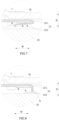
FIG. 7 is a schematic view of a first electrode tab of the secondary battery according to the present invention. -
FIG. 8 is another schematic view of the first electrode tab of the secondary battery according to the present invention. -
FIG. 9 is a schematic view of a first connecting piece of the secondary battery according to the present invention; -
FIG. 10 is another schematic view of the first connecting piece of the secondary battery according to the present invention. - Reference numerals in figures are represented as follows:
- 1 cap plate
- 11 first electrode terminal
- 12 second electrode terminal
- 2 electrode assembly
- 21 first electrode tab
- 211 connecting section
- 212 bending section
- 22 second electrode tab
- 23 main body
- 21 first electrode tab
- 3 first connecting piece
- 31 first electrode terminal connecting portion
- 32 first electrode tab connecting portion
- 321 first electrode tab connecting sub-portion
- 322 first electrode tab jointing sub-portion
- 33 first fusing portion
331 fusing sub-portion
- 4 insulating piece
- 5 insulating bar
- 6 welding protecting piece
- 7 second connecting piece
- E edge
- O opening
- G notch
- S insulating adhesive
- L length direction
- W width direction
- H height direction
- Hereinafter a secondary battery according to the present invention will be described in detail in combination with the figures.
- Referring to
FIGs. 1-10 , a secondary battery according to the present invention comprises acap plate 1, anelectrode assembly 2 and a first connectingpiece 3. Thecap plate 1 is provided with afirst electrode terminal 11 and asecond electrode terminal 12 which are opposite in electrical polarity. Theelectrode assembly 2 comprises amain body 23, afirst electrode tab 21 and asecond electrode tab 22, thefirst electrode tab 21 and thesecond electrode tab 22 are provided to themain body 23 and opposite in electrical polarity. The first connectingpiece 3 is connected in series between thefirst electrode tab 21 and thefirst electrode terminal 11. Thesecond electrode tab 22 is electrically connected with thesecond electrode terminal 12. The first connectingpiece 3 includes a first electrodeterminal connecting portion 31, a first electrodetab connecting portion 32 and afirst fusing portion 33, the first electrodeterminal connecting portion 31 is fixed to and electrically connected with thefirst electrode terminal 11, the first electrodetab connecting portion 32 is fixed to and electrically connected with thefirst electrode tab 21, and thefirst fusing portion 33 is connected in series between the first electrodeterminal connecting portion 31 and the first electrodetab connecting portion 32. The secondary battery further comprises aninsulating piece 4 adhered on a surface of the first connectingpiece 3 which is connected with thefirst electrode tab 21, and theinsulating piece 4 at least covers an edge E of the first electrodeterminal connecting portion 31 close to thefirst electrode tab 21, so as to isolate thefirst electrode tab 21 from the first electrodeterminal connecting portion 31. - In the secondary battery according to the present invention, the
insulating piece 4 can avoid thefirst electrode tab 21 fixed to the first electrodetab connecting portion 32 directly contacting the edge E of the first electrodeterminal connecting portion 31 close to thefirst electrode tab 21 if thefirst electrode tab 21 is too long, prevent a failure of thefirst fusing portion 33 caused by an electrical connection between thefirst electrode tab 21 and the first electrodeterminal connecting portion 31, and improve safety performance of the secondary battery. - In the secondary battery according to the present invention, an area of the edge E depends on a length of the
first electrode tab 21 which may extend to the first electrodeterminal connecting portion 31. The insulatingpiece 4 is adhered on the first connectingpiece 3 before welding the first connectingpiece 3 to thefirst electrode terminal 11, so in order to realize the welding, the insulatingpiece 4 cannot cover a part of the first electrodeterminal connecting portion 31 which is welded with thefirst electrode terminal 11. - In the secondary battery according to the present invention, referring to
FIG. 5 andFIG. 10 , thefirst fusing portion 33 is formed by providing an opening O in the first connectingpiece 3, and thefirst fusing portion 33 includes fusingsub-portions 331 provided at two sides of the opening O respectively along a width direction W. - In the secondary battery according to the present invention, referring to
FIG. 9 , thefirst fusing portion 33 is formed by providing notches G in the first connectingpiece 3, and the notches G are provided at two sides of thefirst fusing portion 33 respectively along the width direction W. - In the secondary battery according to the present invention, an overcurrent sectional area of the
first fusing portion 33 is smaller than an overcurrent sectional area of the first electrodeterminal connecting portion 31 and an overcurrent sectional area of the first electrode tab connecting portion 32 (due to provision of the opening O or the notches G ), therefore, when the high current flows through the first connectingpiece 3, thefirst fusing portion 33 will be fused in time so as to quickly cut off the electrical connection between thefirst electrode tab 21 and thefirst electrode terminal 11, and prevent thermal runaway of the secondary battery. - In the secondary battery according to the present invention, referring to
FIG. 2 andFIG. 9 , the first electrodeterminal connecting portion 31, the first electrodetab connecting portion 32 and thefirst fusing portion 33 extend in a length direction L. Correspondingly, the insulatingpiece 4 at least covers the edge E of the first electrodeterminal connecting portion 31 connected with thefirst fusing portion 33 in the length direction L. Referring toFIG. 2 , in order to ensure an overcurrent sectional area of thefirst electrode tab 21, thefirst electrode tab 21 needs to have a sufficient large length in the length direction L; in the process of welding thefirst electrode tab 21 and the first electrodetab connecting portion 32, thefirst electrode tab 21 may contact the edge E of the first electrodeterminal connecting portion 31 because of the welding misalignment or the large length of thefirst electrode tab 21, so the insulatingpiece 4 can isolate the edge E from thefirst electrode tab 21, prevent the failure of thefirst fusing portion 33 caused by the electrical connection between thefirst electrode tab 21 and the first electrodeterminal connecting portion 31, and improve safety performance of the secondary battery. - In the secondary battery according to the present invention, referring to
FIG. 5 andFIG. 10 , theelectrode assembly 2 is provided as multiple in number. The first electrodetab connecting portion 32 includes two first electrodetab connecting sub-portions 321 and a first electrodetab jointing sub-portion 322. The two first electrodetab connecting sub-portions 321 extend along the length direction L, and each first electrodetab connecting sub-portion 321 is fixed to and electrically connected with thefirst electrode tab 21 of the correspondingelectrode assembly 2. The first electrodetab jointing sub-portion 322 extends along the width direction W, and two ends of the first electrodetab jointing sub-portion 322 are connected with the two first electrodetab connecting sub-portions 321 respectively. The first electrodeterminal connecting portion 31 is positioned between the two first electrodetab connecting sub-portions 321 and extends along the length direction L; thefirst fusing portion 33 extends along the length direction L and is connected between the first electrodetab jointing sub-portion 322 and the first electrodeterminal connecting portion 31. - In the secondary battery according to the present invention, an extending direction and an arranging way of the two first electrode tab connecting sub-portions 321 (the two first electrode
tab connecting sub-portions 321 are the same as the first electrodeterminal connecting portion 31 in the extending direction, and are provided at two sides of the first electrodeterminal connecting portion 31 respectively along the width direction W) can increase a contact area between thefirst electrode tab 21 of theelectrode assembly 2 and the corresponding first electrodetab connecting sub-portion 321, thereby increasing the overcurrent area. - In the secondary battery according to the present invention, referring to
FIG. 5 andFIG. 10 , the insulatingpiece 4 at least covers the two edges E of the first electrodeterminal connecting portion 31 which are respectively positioned at two sides of the first electrodeterminal connecting portion 31 along the width direction W. Referring toFIG. 5 , in order to ensure the overcurrent sectional area of thefirst electrode tab 21, thefirst electrode tab 21 needs to have a sufficient large width in the width direction W; in the process of welding thefirst electrode tab 21 and the corresponding first electrodetab connecting sub-portion 321, thefirst electrode tab 21 will contact the edge E of the first electrodeterminal connecting portion 31 because of the welding misalignment or the large width of thefirst electrode tab 21, so the insulatingpiece 4 can isolate the corresponding edge E from thefirst electrode tab 21, prevent the failure of thefirst fusing portion 33 caused by the electrical connection between thefirst electrode tab 21 and the first electrodeterminal connecting portion 31, and improve safety performance of the secondary battery. - In the secondary battery according to the present invention, referring to
FIG. 5 , the secondary battery further comprises two insulatingbars 5, each insulatingbar 5 is provided in a gap between the first electrodeterminal connecting portion 31 and the first electrodetab connecting sub-portion 321, and each insulatingbar 5 is not lower than a surface of the first connectingpiece 3 which is connected with thefirst electrode tab 21 along a height direction H (in other words, each insulatingbar 5 is not lower than a surface of the first electrodeterminal connecting portion 31 which faces themain body 23 of theelectrode assembly 2 along the height direction H). Thefirst electrode tab 21 may extend beyond the gap and extend to the edge E of the first electrodeterminal connecting portion 31 if thefirst electrode tab 21 is too long, thereby leading to a directly contact between thefirst electrode tab 21 and the first electrodeterminal connecting portion 31, and resulting in the failure of thefirst fusing portion 33. Because the two insulatingbars 5 are respectively provided in the two gaps and each insulatingbar 5 is not lower than the surface of the first connectingpiece 3 which is connected with thefirst electrode tab 21 along the height direction H, the insulatingbars 5 can function for isolation and prevent thefirst electrode tab 21 from electrically connecting with the first electrode terminal connecting portion 31 (if each insulatingbar 5 is flush with the surface of the first connectingpiece 3 which is connected with thefirst electrode tab 21 along the height direction H, each insulatingbar 5 can avoid thefirst electrode tab 21 electrically connecting with a side wall of the first electrodeterminal connecting portion 31 which is used to form the corresponding gap, and if each insulatingbar 5 is higher than the surface of the first connectingpiece 3 which is connected with thefirst electrode tab 21 along the height direction H, each insulatingbar 5 can further avoid thefirst electrode tab 21 contacting the edge E of the first electrode terminal connecting portion 31). In addition, the "not lower than" and the "higher than" are with respect to the height direction H as shown inFIG. 5 , in other words, each insulatingbar 5 is flush with the first connectingpiece 3 or is protruding from the first connectingpiece 3 along a direction toward theelectrode assembly 2 after the secondary battery is formed as a finished product as shown inFIG. 4 . - In the secondary battery according to the present invention, referring to
FIG. 1, FIG. 2 andFIG. 5 , the insulatingpiece 4 further covers thefirst fusing portion 33. If thefirst electrode tab 21 contacts the residual part of thefirst fusing portion 33 which is connected with the first electrodeterminal connecting portion 31 after thefirst fusing portion 33 is fused, it will lead to the failure of thefirst fusing portion 33 too, therefore, the insulatingpiece 4 covers thefirst fusing portion 33 to isolate thefirst fusing portion 33 from thefirst electrode tab 21, prevent the failure of thefirst fusing portion 33 and improve the safety performance of the secondary battery. - In the secondary battery according to the present invention, referring to
FIG. 7 and FIG. 8 , thefirst electrode tab 21 includes a connectingsection 211 and abending section 212. An outer side of the connectingsection 211 is securely connected with the first electrodetab connecting portion 32; thebending section 212 bends and is connected between themain body 23 of theelectrode assembly 2 and the connectingsection 211, and an angle between the connectingsection 211 and thebending section 212 is less than 120 degrees. - In the secondary battery according to the present invention, referring to
FIG. 8 , the angle between the connectingsection 211 and thebending section 212 ranges from 85 degrees to 95 degrees. At this time, thebending section 212 extends nearly along the thickness direction T, so as to prevent short circuit caused by thebending section 212 when thebending section 212 is pressed down. - In the secondary battery according to the present invention, referring to
FIG. 7 , the angle between the connectingsection 211 and thebending section 212 ranges from 0 degrees to 45 degrees. At this time, thebending section 212 nearly folds back onto the connectingsection 211, thereby effectively reducing the space occupied by thefirst electrode tab 21, and promoting a utilization rate of the space inside the secondary battery. - In the secondary battery according to the present invention, referring to
FIG. 7 and FIG. 8 , the secondary battery further comprises an insulating adhesive S, the insulating adhesive S at least is adhered on an inside portion of the connectingsection 211 which directly faces themain body 23 of theelectrode assembly 2. When thecap plate 1 is assembled to a case (not shown) receiving theelectrode assembly 2, thecap plate 1 will press down thefirst electrode tab 21 to easily result in that the connecting section 211 (especially the portion of the connectingsection 211 which directly faces themain body 23 of the electrode assembly 2) of thefirst electrode tab 21 will directly contact the main body 23 (especially an electrode plate of themain body 23 which is opposite to thefirst electrode tab 21 in electrical polarity) of theelectrode assembly 2, thereby resulting in short circuit; but it can avoid the short circuit of theelectrode assembly 2 and improve the safety performance of the secondary battery by provision of the insulating adhesive S. - In the secondary battery according to the present invention, referring to
FIG. 7 and FIG. 8 , preferably, each of the inside portion of the connectingsection 211 and an inside portion of thebending section 212 is covered by the insulating adhesive S. - In the secondary battery according to the present invention, referring to
FIG. 7 and FIG. 8 , the secondary battery further comprises an insulating adhesive S adhered on an outside portion of thebending section 212. When thecap plate 1 is assembled to the case (not shown) receiving theelectrode assembly 2, thefirst electrode tab 21 will be pressed down and bent, and the outside portion of thebending section 212 will easily contact the case, thereby resulting in short circuit; but it can avoid the short circuit of theelectrode assembly 2 and improve the safety performance of the secondary battery by provision of the insulating adhesive S which covers the outside portion of thebending section 212. - In the secondary battery according to the present invention, referring to
FIG. 1, FIG. 2 ,FIG. 3 andFIG. 5 , the secondary battery further comprises a second connectingpiece 7 connected in series between thesecond electrode tab 22 andsecond electrode terminal 12. - In the secondary battery according to the present invention, the secondary battery further comprises a plurality of
welding protecting pieces 6, and eachwelding protecting piece 6 is provided on afirst electrode tab 21 or asecond electrode tab 22. Thewelding protecting piece 6, the correspondingfirst electrode tab 21 and the first connectingpiece 3 are securely connected together by ultrasonic welding; thewelding protecting piece 6, the correspondingsecond electrode tab 22 and the second connectingpiece 7 are securely connected together by ultrasonic welding. Thewelding protecting pieces 6 can improve connection strength between thefirst electrode tab 21 and the first connectingpiece 3 and connection strength between thesecond electrode tab 22 and the second connectingpiece 7. An insulating adhesive tape is adhered on weld zones formed during the ultrasonic welding. Metal scraps generated during the welding can be fixed to the insulating adhesive tape, so the insulating adhesive tape can prevent the metal scraps from entering into the inside of theelectrode assembly 2, also function for insulation and avoid the short circuit of theelectrode assembly 2.
Claims (7)
- A secondary battery, comprising:a cap plate (1) provided with a first electrode terminal (11) and a second electrode terminal (12);multiple electrode assemblies (2), each electrode assembly (2) comprising a main body (23), a first electrode tab (21) provided to the main body (23) and a second electrode tab (22) provided to the main body (23); anda first connecting piece (3) connected between the first electrode tab (21) and the first electrode terminal (11);the second electrode tab (22) being electrically connected with the second electrode terminal (12);whereinthe first connecting piece (3) includes a first electrode terminal connecting portion (31), a first electrode tab connecting portion (32) and a first fusing portion (33), the first electrode terminal connecting portion (31) is fixed to the first electrode terminal (11), the first electrode tab connecting portion (32) is fixed to the first electrode tab (21), and the first fusing portion (33) is connected between the first electrode terminal connecting portion (31) and the first electrode tab connecting portion (32);characterized in thatthe first connecting piece (3) is wholly positioned at a side of the main body (23) of the electrode assembly (2), the side of the main body (23) of the electrode assembly (2) faces the cap plate (1) and is positioned in a height direction (H);the secondary battery further comprises an insulating piece (4) adhered on a surface of the first connecting piece (3), the surface of the first connecting piece (3) is connected with the first electrode tab (21);the first electrode tab connecting portion (32) includes two first electrode tab connecting sub-portions (321) and a first electrode tab jointing sub-portion (322);the two first electrode tab connecting sub-portions (321) extend along a length direction (L), and each first electrode tab connecting sub-portion (321) is fixed to and electrically connected with the first electrode tab (21) of the corresponding electrode assembly (2);the first electrode tab jointing sub-portion (322) extends along a width direction (W), and two ends of the first electrode tab jointing sub-portion (322) are connected with the two first electrode tab connecting sub-portions (321) respectively;the first electrode terminal connecting portion (31) is positioned between the two first electrode tab connecting sub-portions (321) and extends along the length direction (L);the first fusing portion (33) extends along the length direction (L) and is connected between the first electrode tab jointing sub-portion (322) and the first electrode terminal connecting portion (31);the insulating piece (4) at least covers two edges (E) of the first electrode terminal connecting portion (31) which are respectively positioned at two sides of the first electrode terminal connecting portion (31) along the width direction (W) so as to avoid the first electrode tab (21) directly contacting the edges (E).
- The secondary battery according to Claim 1, whereinthe first fusing portion (33) is formed by providing an opening (O) in the first connecting piece (3), and the first fusing portion (33) includes fusing sub-portions (331) provided at two sides of the opening (O) respectively along a width direction (W); orthe first fusing portion (33) is formed by providing notches (G) in the first connecting piece (3), and the notches (G) are provided at two sides of the first fusing portion (33) respectively along the width direction (W).
- The secondary battery according to Claim 1, wherein
the secondary battery further comprises two insulating bars (5), each insulating bar (5) is provided in a gap between the first electrode terminal connecting portion (31) and the first electrode tab connecting sub-portion (321), and each insulating bar (5) is not lower than the surface of the first connecting piece (3) which is connected with the first electrode tab (21) along the height direction (H). - The secondary battery according to Claim 1, wherein
the insulating piece (4) further covers the first fusing portion (33). - The secondary battery according to Claim 1, whereinthe first electrode tab (21) includes a connecting section (211) and a bending section (212);an outer side of the connecting section (211) is connected with the first electrode tab connecting portion (32);the bending section (212) bends and is connected between the main body (23) of the electrode assembly (2) and the connecting section (212), an angle between the connecting section (211) and the bending section (212) is less than 120 degrees.
- The secondary battery according to Claim 5, whereinthe angle between the connecting section (211) and the bending section (212) ranges from 85 degrees to 95 degrees; orthe angle between the connecting section (211) and the bending section (212) ranges from 0 degrees to 45 degrees
- The secondary battery according to Claim 5, whereinthe secondary battery further comprises an insulating adhesive (S), the insulating adhesive (S) is adhered on an inside portion of the connecting section (211) which directly faces the main body (23) of the electrode assembly (2); and/orthe secondary battery further comprises an insulating adhesive (S) adhered on an outside portion of the bending section (212).
Applications Claiming Priority (1)
| Application Number | Priority Date | Filing Date | Title |
|---|---|---|---|
| CN201621318451.0U CN206250260U (en) | 2016-12-02 | 2016-12-02 | Secondary cell |
Publications (2)
| Publication Number | Publication Date |
|---|---|
| EP3331052A1 EP3331052A1 (en) | 2018-06-06 |
| EP3331052B1 true EP3331052B1 (en) | 2024-11-20 |
Family
ID=59005030
Family Applications (1)
| Application Number | Title | Priority Date | Filing Date |
|---|---|---|---|
| EP17204308.5A Active EP3331052B1 (en) | 2016-12-02 | 2017-11-29 | Secondary battery |
Country Status (4)
| Country | Link |
|---|---|
| US (2) | US10916756B2 (en) |
| EP (1) | EP3331052B1 (en) |
| CN (1) | CN206250260U (en) |
| HU (1) | HUE069990T2 (en) |
Families Citing this family (17)
| Publication number | Priority date | Publication date | Assignee | Title |
|---|---|---|---|---|
| CN109698385B (en) * | 2017-10-20 | 2024-06-18 | 宁德时代新能源科技股份有限公司 | Secondary battery |
| CN109148806A (en) * | 2018-07-18 | 2019-01-04 | 湖北锂诺新能源科技有限公司 | The cell polar ear and top cover connection method and connection structure of power battery |
| CN108922993A (en) * | 2018-08-14 | 2018-11-30 | 江苏海基新能源股份有限公司 | The rectangular winding multi-pole lug lithium ion battery of one kind and its assembly method |
| CN109244348B (en) * | 2018-09-14 | 2021-11-23 | 湖北亿纬动力有限公司 | Battery assembly process and assembly device |
| CN109326746B (en) * | 2018-10-25 | 2024-06-18 | 江苏正力新能电池技术有限公司 | A battery top cover glue sticking structure and glue sticking method |
| CN109659481B (en) * | 2018-12-24 | 2022-04-12 | 湖北亿纬动力有限公司 | Battery cell connecting sheet, battery and assembling method |
| US20220393250A1 (en) * | 2019-11-01 | 2022-12-08 | Sanyo Electric Co., Ltd. | Electrode plate, nonaqueous electrolyte secondary battery, and method for producing electrode plate |
| CN111540873A (en) * | 2020-04-30 | 2020-08-14 | 中航锂电(洛阳)有限公司 | Connector protection components and battery modules |
| KR102848220B1 (en) | 2021-04-30 | 2025-08-21 | 컨템포러리 엠퍼렉스 테크놀로지 (홍콩) 리미티드 | Battery cell, manufacturing method thereof, manufacturing system, battery and power consumption device |
| CN116780125A (en) * | 2021-07-27 | 2023-09-19 | 宁德时代新能源科技股份有限公司 | Battery cell, battery and electricity utilization device |
| CN114142180B (en) * | 2021-11-30 | 2024-01-26 | 江苏正力新能电池技术有限公司 | Battery switching member, battery and battery assembling method |
| US12253102B2 (en) * | 2022-03-07 | 2025-03-18 | Sumitomo Wiring Systems, Ltd. | Clamp assembly configured for vertical tightening |
| CN114583415B (en) * | 2022-04-15 | 2022-08-09 | 宁德新能源科技有限公司 | Battery and electronic device |
| CN115275539B (en) * | 2022-08-12 | 2024-01-23 | 郑州比克电池有限公司 | Cylindrical lithium battery insulation structure |
| CN118435432A (en) * | 2022-08-29 | 2024-08-02 | 宁德时代新能源科技股份有限公司 | Top cover assembly, battery cell, battery and electrical device |
| CN115663412B (en) * | 2022-11-11 | 2023-03-28 | 深圳海润新能源科技有限公司 | Terminal subassembly, top cap subassembly, energy memory and consumer |
| CN119253207B (en) * | 2024-12-06 | 2025-02-28 | 中创新航科技集团股份有限公司 | Battery pack |
Family Cites Families (12)
| Publication number | Priority date | Publication date | Assignee | Title |
|---|---|---|---|---|
| KR101094039B1 (en) | 2009-10-01 | 2011-12-19 | 삼성에스디아이 주식회사 | Current blocking device and secondary battery having same |
| CN102208594B (en) | 2010-03-30 | 2015-04-29 | 三星Sdi株式会社 | Secondary battery |
| US8802281B2 (en) * | 2010-08-05 | 2014-08-12 | Samsung Sdi Co., Ltd. | Secondary battery with movement prevention tape |
| US8889292B2 (en) | 2011-10-13 | 2014-11-18 | Samsung Sdi Co., Ltd. | Rechargeable battery |
| KR101683209B1 (en) * | 2011-12-06 | 2016-12-07 | 삼성에스디아이 주식회사 | Rechargeable battery |
| KR101693290B1 (en) | 2013-04-18 | 2017-01-05 | 삼성에스디아이 주식회사 | Rechargeable battery module |
| US9660249B2 (en) | 2013-10-01 | 2017-05-23 | Samsung Sdi Co., Ltd. | Rechargeable battery having a fuse |
| KR102306440B1 (en) * | 2014-08-14 | 2021-09-29 | 삼성에스디아이 주식회사 | Rechargeable battery |
| CN204927440U (en) | 2015-09-24 | 2015-12-30 | 宁德时代新能源科技有限公司 | Lamination formula secondary cell |
| CN205376627U (en) | 2016-02-26 | 2016-07-06 | 宁德时代新能源科技股份有限公司 | Secondary battery |
| CN205429058U (en) | 2016-03-18 | 2016-08-03 | 宁德时代新能源科技股份有限公司 | Secondary battery |
| KR102629053B1 (en) * | 2016-08-08 | 2024-01-23 | 삼성에스디아이 주식회사 | Rechargeable battery having current collector |
-
2016
- 2016-12-02 CN CN201621318451.0U patent/CN206250260U/en active Active
-
2017
- 2017-11-17 US US15/816,981 patent/US10916756B2/en active Active
- 2017-11-29 EP EP17204308.5A patent/EP3331052B1/en active Active
- 2017-11-29 HU HUE17204308A patent/HUE069990T2/en unknown
-
2020
- 2020-12-18 US US17/127,622 patent/US11557816B2/en active Active
Also Published As
| Publication number | Publication date |
|---|---|
| EP3331052A1 (en) | 2018-06-06 |
| HUE069990T2 (en) | 2025-04-28 |
| US20180159107A1 (en) | 2018-06-07 |
| CN206250260U (en) | 2017-06-13 |
| US10916756B2 (en) | 2021-02-09 |
| US20210111466A1 (en) | 2021-04-15 |
| US11557816B2 (en) | 2023-01-17 |
Similar Documents
| Publication | Publication Date | Title |
|---|---|---|
| US11557816B2 (en) | Secondary battery | |
| US11296391B2 (en) | Secondary battery and assembly therefor | |
| CN108155335B (en) | Assembly for secondary battery | |
| EP3331062B1 (en) | Secondary battery | |
| EP3542389B1 (en) | Ventilated fuse housing | |
| EP3386004B1 (en) | Secondary battery | |
| KR102253021B1 (en) | Rechargeable battery having fuse and battery module | |
| EP2597705B1 (en) | Rechargeable battery | |
| JP5704645B2 (en) | Secondary battery | |
| KR101744090B1 (en) | Rechargeable battery having short member | |
| CN207818736U (en) | Rechargeable Battery | |
| EP3474342B1 (en) | Battery cap assembly and secondary battery | |
| EP3255698A1 (en) | Top cover of power battery and power battery | |
| US10074842B2 (en) | Secondary battery | |
| EP3149789B1 (en) | Battery | |
| CN103050652B (en) | Secondary battery | |
| KR102416528B1 (en) | Rechargeable battery | |
| US8835042B2 (en) | Battery pack | |
| EP2378591B1 (en) | Secondary battery | |
| KR102173754B1 (en) | Secondary battery and the method of manufacturing the same | |
| JP5200072B2 (en) | battery | |
| KR102911277B1 (en) | secondary battery, battery pack and battery module |
Legal Events
| Date | Code | Title | Description |
|---|---|---|---|
| PUAI | Public reference made under article 153(3) epc to a published international application that has entered the european phase |
Free format text: ORIGINAL CODE: 0009012 |
|
| STAA | Information on the status of an ep patent application or granted ep patent |
Free format text: STATUS: REQUEST FOR EXAMINATION WAS MADE |
|
| 17P | Request for examination filed |
Effective date: 20171129 |
|
| AK | Designated contracting states |
Kind code of ref document: A1 Designated state(s): AL AT BE BG CH CY CZ DE DK EE ES FI FR GB GR HR HU IE IS IT LI LT LU LV MC MK MT NL NO PL PT RO RS SE SI SK SM TR |
|
| AX | Request for extension of the european patent |
Extension state: BA ME |
|
| STAA | Information on the status of an ep patent application or granted ep patent |
Free format text: STATUS: EXAMINATION IS IN PROGRESS |
|
| 17Q | First examination report despatched |
Effective date: 20201020 |
|
| REG | Reference to a national code |
Ref country code: DE Ref legal event code: R079 Free format text: PREVIOUS MAIN CLASS: H01M0002040000 Ipc: H01M0050147000 Ref country code: DE Ref legal event code: R079 Ref document number: 602017086205 Country of ref document: DE Free format text: PREVIOUS MAIN CLASS: H01M0002040000 Ipc: H01M0050147000 |
|
| GRAP | Despatch of communication of intention to grant a patent |
Free format text: ORIGINAL CODE: EPIDOSNIGR1 |
|
| RIC1 | Information provided on ipc code assigned before grant |
Ipc: H01M 50/566 20210101ALN20240808BHEP Ipc: H01M 50/583 20210101ALI20240808BHEP Ipc: H01M 50/581 20210101ALI20240808BHEP Ipc: H01M 50/55 20210101ALI20240808BHEP Ipc: H01M 50/528 20210101ALI20240808BHEP Ipc: H01M 50/176 20210101ALI20240808BHEP Ipc: H01M 50/147 20210101AFI20240808BHEP |
|
| STAA | Information on the status of an ep patent application or granted ep patent |
Free format text: STATUS: GRANT OF PATENT IS INTENDED |
|
| RAP1 | Party data changed (applicant data changed or rights of an application transferred) |
Owner name: CONTEMPORARY AMPEREX TECHNOLOGY(HONG KONG) LIMITED |
|
| GRAS | Grant fee paid |
Free format text: ORIGINAL CODE: EPIDOSNIGR3 |
|
| INTG | Intention to grant announced |
Effective date: 20240912 |
|
| GRAA | (expected) grant |
Free format text: ORIGINAL CODE: 0009210 |
|
| STAA | Information on the status of an ep patent application or granted ep patent |
Free format text: STATUS: THE PATENT HAS BEEN GRANTED |
|
| AK | Designated contracting states |
Kind code of ref document: B1 Designated state(s): AL AT BE BG CH CY CZ DE DK EE ES FI FR GB GR HR HU IE IS IT LI LT LU LV MC MK MT NL NO PL PT RO RS SE SI SK SM TR |
|
| REG | Reference to a national code |
Ref country code: GB Ref legal event code: FG4D |
|
| REG | Reference to a national code |
Ref country code: CH Ref legal event code: EP |
|
| REG | Reference to a national code |
Ref country code: DE Ref legal event code: R096 Ref document number: 602017086205 Country of ref document: DE |
|
| REG | Reference to a national code |
Ref country code: IE Ref legal event code: FG4D |
|
| P01 | Opt-out of the competence of the unified patent court (upc) registered |
Free format text: CASE NUMBER: APP_1235/2025 Effective date: 20250109 |
|
| REG | Reference to a national code |
Ref country code: LT Ref legal event code: MG9D |
|
| REG | Reference to a national code |
Ref country code: NL Ref legal event code: MP Effective date: 20241120 |
|
| PG25 | Lapsed in a contracting state [announced via postgrant information from national office to epo] |
Ref country code: IS Free format text: LAPSE BECAUSE OF FAILURE TO SUBMIT A TRANSLATION OF THE DESCRIPTION OR TO PAY THE FEE WITHIN THE PRESCRIBED TIME-LIMIT Effective date: 20250320 Ref country code: HR Free format text: LAPSE BECAUSE OF FAILURE TO SUBMIT A TRANSLATION OF THE DESCRIPTION OR TO PAY THE FEE WITHIN THE PRESCRIBED TIME-LIMIT Effective date: 20241120 Ref country code: PT Free format text: LAPSE BECAUSE OF FAILURE TO SUBMIT A TRANSLATION OF THE DESCRIPTION OR TO PAY THE FEE WITHIN THE PRESCRIBED TIME-LIMIT Effective date: 20250320 |
|
| PG25 | Lapsed in a contracting state [announced via postgrant information from national office to epo] |
Ref country code: NL Free format text: LAPSE BECAUSE OF FAILURE TO SUBMIT A TRANSLATION OF THE DESCRIPTION OR TO PAY THE FEE WITHIN THE PRESCRIBED TIME-LIMIT Effective date: 20241120 Ref country code: FI Free format text: LAPSE BECAUSE OF FAILURE TO SUBMIT A TRANSLATION OF THE DESCRIPTION OR TO PAY THE FEE WITHIN THE PRESCRIBED TIME-LIMIT Effective date: 20241120 |
|
| REG | Reference to a national code |
Ref country code: AT Ref legal event code: MK05 Ref document number: 1744432 Country of ref document: AT Kind code of ref document: T Effective date: 20241120 |
|
| PG25 | Lapsed in a contracting state [announced via postgrant information from national office to epo] |
Ref country code: BG Free format text: LAPSE BECAUSE OF FAILURE TO SUBMIT A TRANSLATION OF THE DESCRIPTION OR TO PAY THE FEE WITHIN THE PRESCRIBED TIME-LIMIT Effective date: 20241120 |
|
| PG25 | Lapsed in a contracting state [announced via postgrant information from national office to epo] |
Ref country code: ES Free format text: LAPSE BECAUSE OF FAILURE TO SUBMIT A TRANSLATION OF THE DESCRIPTION OR TO PAY THE FEE WITHIN THE PRESCRIBED TIME-LIMIT Effective date: 20241120 |
|
| PG25 | Lapsed in a contracting state [announced via postgrant information from national office to epo] |
Ref country code: NO Free format text: LAPSE BECAUSE OF FAILURE TO SUBMIT A TRANSLATION OF THE DESCRIPTION OR TO PAY THE FEE WITHIN THE PRESCRIBED TIME-LIMIT Effective date: 20250220 |
|
| PG25 | Lapsed in a contracting state [announced via postgrant information from national office to epo] |
Ref country code: AT Free format text: LAPSE BECAUSE OF FAILURE TO SUBMIT A TRANSLATION OF THE DESCRIPTION OR TO PAY THE FEE WITHIN THE PRESCRIBED TIME-LIMIT Effective date: 20241120 Ref country code: LV Free format text: LAPSE BECAUSE OF FAILURE TO SUBMIT A TRANSLATION OF THE DESCRIPTION OR TO PAY THE FEE WITHIN THE PRESCRIBED TIME-LIMIT Effective date: 20241120 Ref country code: GR Free format text: LAPSE BECAUSE OF FAILURE TO SUBMIT A TRANSLATION OF THE DESCRIPTION OR TO PAY THE FEE WITHIN THE PRESCRIBED TIME-LIMIT Effective date: 20250221 |
|
| PG25 | Lapsed in a contracting state [announced via postgrant information from national office to epo] |
Ref country code: PL Free format text: LAPSE BECAUSE OF FAILURE TO SUBMIT A TRANSLATION OF THE DESCRIPTION OR TO PAY THE FEE WITHIN THE PRESCRIBED TIME-LIMIT Effective date: 20241120 |
|
| REG | Reference to a national code |
Ref country code: HU Ref legal event code: AG4A Ref document number: E069990 Country of ref document: HU |
|
| PG25 | Lapsed in a contracting state [announced via postgrant information from national office to epo] |
Ref country code: RS Free format text: LAPSE BECAUSE OF FAILURE TO SUBMIT A TRANSLATION OF THE DESCRIPTION OR TO PAY THE FEE WITHIN THE PRESCRIBED TIME-LIMIT Effective date: 20250220 |
|
| REG | Reference to a national code |
Ref country code: CH Ref legal event code: PL |
|
| PG25 | Lapsed in a contracting state [announced via postgrant information from national office to epo] |
Ref country code: SM Free format text: LAPSE BECAUSE OF FAILURE TO SUBMIT A TRANSLATION OF THE DESCRIPTION OR TO PAY THE FEE WITHIN THE PRESCRIBED TIME-LIMIT Effective date: 20241120 |
|
| PG25 | Lapsed in a contracting state [announced via postgrant information from national office to epo] |
Ref country code: DK Free format text: LAPSE BECAUSE OF FAILURE TO SUBMIT A TRANSLATION OF THE DESCRIPTION OR TO PAY THE FEE WITHIN THE PRESCRIBED TIME-LIMIT Effective date: 20241120 |
|
| PG25 | Lapsed in a contracting state [announced via postgrant information from national office to epo] |
Ref country code: LU Free format text: LAPSE BECAUSE OF NON-PAYMENT OF DUE FEES Effective date: 20241129 |
|
| REG | Reference to a national code |
Ref country code: CH Ref legal event code: PL |
|
| PG25 | Lapsed in a contracting state [announced via postgrant information from national office to epo] |
Ref country code: EE Free format text: LAPSE BECAUSE OF FAILURE TO SUBMIT A TRANSLATION OF THE DESCRIPTION OR TO PAY THE FEE WITHIN THE PRESCRIBED TIME-LIMIT Effective date: 20241120 |
|
| PG25 | Lapsed in a contracting state [announced via postgrant information from national office to epo] |
Ref country code: CH Free format text: LAPSE BECAUSE OF NON-PAYMENT OF DUE FEES Effective date: 20241130 |
|
| PG25 | Lapsed in a contracting state [announced via postgrant information from national office to epo] |
Ref country code: RO Free format text: LAPSE BECAUSE OF FAILURE TO SUBMIT A TRANSLATION OF THE DESCRIPTION OR TO PAY THE FEE WITHIN THE PRESCRIBED TIME-LIMIT Effective date: 20241120 |
|
| PG25 | Lapsed in a contracting state [announced via postgrant information from national office to epo] |
Ref country code: SK Free format text: LAPSE BECAUSE OF FAILURE TO SUBMIT A TRANSLATION OF THE DESCRIPTION OR TO PAY THE FEE WITHIN THE PRESCRIBED TIME-LIMIT Effective date: 20241120 |
|
| PG25 | Lapsed in a contracting state [announced via postgrant information from national office to epo] |
Ref country code: CZ Free format text: LAPSE BECAUSE OF FAILURE TO SUBMIT A TRANSLATION OF THE DESCRIPTION OR TO PAY THE FEE WITHIN THE PRESCRIBED TIME-LIMIT Effective date: 20241120 |
|
| PG25 | Lapsed in a contracting state [announced via postgrant information from national office to epo] |
Ref country code: IT Free format text: LAPSE BECAUSE OF FAILURE TO SUBMIT A TRANSLATION OF THE DESCRIPTION OR TO PAY THE FEE WITHIN THE PRESCRIBED TIME-LIMIT Effective date: 20241120 |
|
| REG | Reference to a national code |
Ref country code: DE Ref legal event code: R097 Ref document number: 602017086205 Country of ref document: DE |
|
| REG | Reference to a national code |
Ref country code: BE Ref legal event code: MM Effective date: 20241130 |
|
| PG25 | Lapsed in a contracting state [announced via postgrant information from national office to epo] |
Ref country code: SE Free format text: LAPSE BECAUSE OF FAILURE TO SUBMIT A TRANSLATION OF THE DESCRIPTION OR TO PAY THE FEE WITHIN THE PRESCRIBED TIME-LIMIT Effective date: 20241120 |
|
| PG25 | Lapsed in a contracting state [announced via postgrant information from national office to epo] |
Ref country code: MC Free format text: LAPSE BECAUSE OF FAILURE TO SUBMIT A TRANSLATION OF THE DESCRIPTION OR TO PAY THE FEE WITHIN THE PRESCRIBED TIME-LIMIT Effective date: 20241120 |
|
| PLBE | No opposition filed within time limit |
Free format text: ORIGINAL CODE: 0009261 |
|
| STAA | Information on the status of an ep patent application or granted ep patent |
Free format text: STATUS: NO OPPOSITION FILED WITHIN TIME LIMIT |
|
| PG25 | Lapsed in a contracting state [announced via postgrant information from national office to epo] |
Ref country code: BE Free format text: LAPSE BECAUSE OF NON-PAYMENT OF DUE FEES Effective date: 20241130 |
|
| 26N | No opposition filed |
Effective date: 20250821 |
|
| PG25 | Lapsed in a contracting state [announced via postgrant information from national office to epo] |
Ref country code: IE Free format text: LAPSE BECAUSE OF NON-PAYMENT OF DUE FEES Effective date: 20241129 |
|
| PGFP | Annual fee paid to national office [announced via postgrant information from national office to epo] |
Ref country code: HU Payment date: 20251107 Year of fee payment: 9 |
|
| PGFP | Annual fee paid to national office [announced via postgrant information from national office to epo] |
Ref country code: DE Payment date: 20251124 Year of fee payment: 9 |
|
| PGFP | Annual fee paid to national office [announced via postgrant information from national office to epo] |
Ref country code: GB Payment date: 20251126 Year of fee payment: 9 |
|
| PGFP | Annual fee paid to national office [announced via postgrant information from national office to epo] |
Ref country code: FR Payment date: 20251128 Year of fee payment: 9 |
|
| PG25 | Lapsed in a contracting state [announced via postgrant information from national office to epo] |
Ref country code: CY Free format text: LAPSE BECAUSE OF FAILURE TO SUBMIT A TRANSLATION OF THE DESCRIPTION OR TO PAY THE FEE WITHIN THE PRESCRIBED TIME-LIMIT; INVALID AB INITIO Effective date: 20171129 |