EP2581965A1 - Rechargeable battery - Google Patents
Rechargeable battery Download PDFInfo
- Publication number
- EP2581965A1 EP2581965A1 EP12159200.0A EP12159200A EP2581965A1 EP 2581965 A1 EP2581965 A1 EP 2581965A1 EP 12159200 A EP12159200 A EP 12159200A EP 2581965 A1 EP2581965 A1 EP 2581965A1
- Authority
- EP
- European Patent Office
- Prior art keywords
- current collecting
- rechargeable battery
- plate
- connection portion
- electrode
- Prior art date
- Legal status (The legal status is an assumption and is not a legal conclusion. Google has not performed a legal analysis and makes no representation as to the accuracy of the status listed.)
- Granted
Links
Images


Classifications
-
- H—ELECTRICITY
- H01—ELECTRIC ELEMENTS
- H01M—PROCESSES OR MEANS, e.g. BATTERIES, FOR THE DIRECT CONVERSION OF CHEMICAL ENERGY INTO ELECTRICAL ENERGY
- H01M4/00—Electrodes
- H01M4/02—Electrodes composed of, or comprising, active material
- H01M4/64—Carriers or collectors
- H01M4/70—Carriers or collectors characterised by shape or form
-
- H—ELECTRICITY
- H01—ELECTRIC ELEMENTS
- H01M—PROCESSES OR MEANS, e.g. BATTERIES, FOR THE DIRECT CONVERSION OF CHEMICAL ENERGY INTO ELECTRICAL ENERGY
- H01M10/00—Secondary cells; Manufacture thereof
- H01M10/04—Construction or manufacture in general
- H01M10/0431—Cells with wound or folded electrodes
-
- H—ELECTRICITY
- H01—ELECTRIC ELEMENTS
- H01M—PROCESSES OR MEANS, e.g. BATTERIES, FOR THE DIRECT CONVERSION OF CHEMICAL ENERGY INTO ELECTRICAL ENERGY
- H01M10/00—Secondary cells; Manufacture thereof
- H01M10/02—Details
-
- H—ELECTRICITY
- H01—ELECTRIC ELEMENTS
- H01M—PROCESSES OR MEANS, e.g. BATTERIES, FOR THE DIRECT CONVERSION OF CHEMICAL ENERGY INTO ELECTRICAL ENERGY
- H01M10/00—Secondary cells; Manufacture thereof
- H01M10/04—Construction or manufacture in general
-
- H—ELECTRICITY
- H01—ELECTRIC ELEMENTS
- H01M—PROCESSES OR MEANS, e.g. BATTERIES, FOR THE DIRECT CONVERSION OF CHEMICAL ENERGY INTO ELECTRICAL ENERGY
- H01M50/00—Constructional details or processes of manufacture of the non-active parts of electrochemical cells other than fuel cells, e.g. hybrid cells
- H01M50/50—Current conducting connections for cells or batteries
- H01M50/531—Electrode connections inside a battery casing
- H01M50/533—Electrode connections inside a battery casing characterised by the shape of the leads or tabs
-
- H—ELECTRICITY
- H01—ELECTRIC ELEMENTS
- H01M—PROCESSES OR MEANS, e.g. BATTERIES, FOR THE DIRECT CONVERSION OF CHEMICAL ENERGY INTO ELECTRICAL ENERGY
- H01M50/00—Constructional details or processes of manufacture of the non-active parts of electrochemical cells other than fuel cells, e.g. hybrid cells
- H01M50/50—Current conducting connections for cells or batteries
- H01M50/531—Electrode connections inside a battery casing
- H01M50/536—Electrode connections inside a battery casing characterised by the method of fixing the leads to the electrodes, e.g. by welding
-
- H—ELECTRICITY
- H01—ELECTRIC ELEMENTS
- H01M—PROCESSES OR MEANS, e.g. BATTERIES, FOR THE DIRECT CONVERSION OF CHEMICAL ENERGY INTO ELECTRICAL ENERGY
- H01M50/00—Constructional details or processes of manufacture of the non-active parts of electrochemical cells other than fuel cells, e.g. hybrid cells
- H01M50/50—Current conducting connections for cells or batteries
- H01M50/531—Electrode connections inside a battery casing
- H01M50/538—Connection of several leads or tabs of wound or folded electrode stacks
-
- H—ELECTRICITY
- H01—ELECTRIC ELEMENTS
- H01M—PROCESSES OR MEANS, e.g. BATTERIES, FOR THE DIRECT CONVERSION OF CHEMICAL ENERGY INTO ELECTRICAL ENERGY
- H01M50/00—Constructional details or processes of manufacture of the non-active parts of electrochemical cells other than fuel cells, e.g. hybrid cells
- H01M50/50—Current conducting connections for cells or batteries
- H01M50/543—Terminals
-
- H—ELECTRICITY
- H01—ELECTRIC ELEMENTS
- H01M—PROCESSES OR MEANS, e.g. BATTERIES, FOR THE DIRECT CONVERSION OF CHEMICAL ENERGY INTO ELECTRICAL ENERGY
- H01M50/00—Constructional details or processes of manufacture of the non-active parts of electrochemical cells other than fuel cells, e.g. hybrid cells
- H01M50/50—Current conducting connections for cells or batteries
- H01M50/572—Means for preventing undesired use or discharge
- H01M50/574—Devices or arrangements for the interruption of current
- H01M50/583—Devices or arrangements for the interruption of current in response to current, e.g. fuses
-
- H—ELECTRICITY
- H01—ELECTRIC ELEMENTS
- H01M—PROCESSES OR MEANS, e.g. BATTERIES, FOR THE DIRECT CONVERSION OF CHEMICAL ENERGY INTO ELECTRICAL ENERGY
- H01M2200/00—Safety devices for primary or secondary batteries
- H01M2200/10—Temperature sensitive devices
- H01M2200/103—Fuse
-
- Y—GENERAL TAGGING OF NEW TECHNOLOGICAL DEVELOPMENTS; GENERAL TAGGING OF CROSS-SECTIONAL TECHNOLOGIES SPANNING OVER SEVERAL SECTIONS OF THE IPC; TECHNICAL SUBJECTS COVERED BY FORMER USPC CROSS-REFERENCE ART COLLECTIONS [XRACs] AND DIGESTS
- Y02—TECHNOLOGIES OR APPLICATIONS FOR MITIGATION OR ADAPTATION AGAINST CLIMATE CHANGE
- Y02E—REDUCTION OF GREENHOUSE GAS [GHG] EMISSIONS, RELATED TO ENERGY GENERATION, TRANSMISSION OR DISTRIBUTION
- Y02E60/00—Enabling technologies; Technologies with a potential or indirect contribution to GHG emissions mitigation
- Y02E60/10—Energy storage using batteries
-
- Y—GENERAL TAGGING OF NEW TECHNOLOGICAL DEVELOPMENTS; GENERAL TAGGING OF CROSS-SECTIONAL TECHNOLOGIES SPANNING OVER SEVERAL SECTIONS OF THE IPC; TECHNICAL SUBJECTS COVERED BY FORMER USPC CROSS-REFERENCE ART COLLECTIONS [XRACs] AND DIGESTS
- Y02—TECHNOLOGIES OR APPLICATIONS FOR MITIGATION OR ADAPTATION AGAINST CLIMATE CHANGE
- Y02P—CLIMATE CHANGE MITIGATION TECHNOLOGIES IN THE PRODUCTION OR PROCESSING OF GOODS
- Y02P70/00—Climate change mitigation technologies in the production process for final industrial or consumer products
- Y02P70/50—Manufacturing or production processes characterised by the final manufactured product
Definitions
- the described technology relates generally to a rechargeable battery. More particularly, the described technology relates generally to a rechargeable battery of which a current collecting member is improved in structure.
- a rechargeable battery can be repeatedly charged and discharged, unlike a primary battery that cannot be recharged.
- a low-capacity rechargeable battery is used for a small portable electronic device such as a mobile phone, a laptop computer, and a camcorder.
- a large-capacity rechargeable battery is widely used as a power supply for driving a motor of a hybrid vehicle and the like.
- the high-output rechargeable battery is configured of a large-capacity battery module in which a plurality of rechargeable batteries are connected to each other in series so as to be used to drive a motor of devices requiring large power, for example, an electric car, or the like.
- the battery module is generally configured by the plurality of rechargeable batteries that are coupled with each other in series, and each of the rechargeable batteries may be formed in a cylindrical shape, a prismatic shape, and the like.
- the described technology has been made in an effort to provide a rechargeable battery improved in safety.
- a rechargeable battery includes a plurality of electrode assemblies each comprising a first electrode, a second electrode, and a separator interposed between the first and second electrodes, each electrode having a coated and an uncoated region, a case for mounting the plurality of electrode assemblies therein, a cap plate for closing an opening in the case, a first terminal protruding through the cap plate and being electrically coupled to a first current collecting member; the first current collecting member mechanically and electrically coupling each first electrode of the plurality of electrode assemblies to the first terminal; the first current collecting member further comprises: a plurality of current collecting plates, each current collecting plate being fixed to an uncoated region of one of the plurality of first electrodes, and a plurality of supporting portions connecting neighboring current collecting plates, wherein the first current collecting member comprises a terminal connection portion and a side plate extending from a lateral side surface of the terminal connection portion and electrically coupling the plurality of current collecting plates to the first terminal.
- the terminal connection portion preferably comprises a fuse portion and the side plate is bent from a side formed by being extended along a direction that crosses a width direction along which the fuse portion is extended.
- the side where the side plate is bent from is preferably disposed at an end of the fuse portion and/or wherein a lateral projection of the fuse portion and the side plate overlaps.
- a first current collecting plate preferably extends from a lower surface of the side plate.
- a second current collecting plate is connected to the first current collecting plate via at least one supporting portion, preferably two supporting portions.
- a first supporting portion may be formed in an upper portion of the first current collecting plate and/or a second supporting portion may be formed in the lower portion of the first current collecting plate.
- the first or second supporting portion preferably comprises a connection portion extending from a side surface of the first current collecting member facing away from the plurality of electrode assemblies; and a guiding portion formed extending from the connection portion to the second current collecting plate.
- Each first electrode comprises an inclined surface between its uncoated and its coated region, the guiding portion being in physical contact with the inclined surface.
- the guiding portion is in directed contact with the inclined surface.
- the guiding portions are preferably inclined with respect to the connection portion to closely attach to the inclined surface.
- a current collecting plate may have a stepped profile with a welding bar and a bent bar formed at a lower end of welding bar and being inclined with respect to the welding bar, and an insertion tip formed at an end portion of the bent bar such that the insertion tip is not in contact with the first electrode.
- the bent bar is inclined with an angle between 5° and 90° with respect to welding bar, more preferably below 90°.
- the shortest distance between two adjacent welding bars is preferably greater than the shortest distance between two adjacent insertion tips.
- a supporting portion may connect two adjacent insertion tips.
- Insulating members are attached to portions of the first current collecting member facing the inside of the case.
- the side plate may comprise a protrusion such that the width of the side plate is larger than the width of the current collecting plates.
- the supporting portion supports movement of the electrode assembly due to impact or vibration so that a short-circuit between the electrode assembly and the case can be prevented.
- FIG. 1 is a perspective view of a rechargeable battery according to a first exemplary embodiment of the present invention and FIG. 2 is a cross-sectional view of FIG. 1 , taken along the line 11-11.
- a rechargeable battery 101 includes a plurality of electrode assemblies 10 formed by winding a positive electrode 11 and a negative electrode 12, interposing a separator 13 therebetween, a case 30 in which the electrode assembly 10 is installed, and a cap assembly 20 coupled to an opening of the case 30.
- the rechargeable battery 101 according to the first exemplary embodiment is exemplarily described as a lithium ion secondary battery formed in the shape of a prism.
- the present invention is not limited thereof, and the present invention may be applied to various shapes of batteries such as a lithium polymer battery or a cylindrical battery.
- the positive electrode 11 and the negative electrode 12 include coated regions where an active material is coated to a current collector formed of a thin metal foil and uncoated regions 11a and 12a where the active material is not coated.
- the positive electrode uncoated region 11a is formed at a first side end of the positive electrode 11 along a length direction of the positive electrode 11, and the negative uncoated region 12a is formed at a second side end of the negative electrode 12 along a length direction of the negative electrode 12.
- the positive electrode 11 and the negative electrode 12 are spirally wound, interposing the separator 13 therebetween.
- the separator 13 is an insulator.
- the present invention is not limited thereto, and the electrode assembly 10 may have a structure where a positive electrode and a negative electrode, each formed of a plurality of sheets are alternately layered, interposing a separator therebetween.
- the case 30 is approximately formed in the shape of a cuboid, and an opening is formed one side thereof.
- the cap assembly 20 includes a cap plate 25 covering the opening of the case 30, a positive terminal 21 protruding to an outer side of the cap plate 25 and electrically connected with the positive electrode 11, a negative terminal 22 protruding to an outer side of the cap plate 25 and electrically connected with the negative electrode 12, and a vent member 27 having a notch 27a formed to be broken according to a predetermined internal pressure.
- the cap plate 25 is formed of a thin plate, and an electrolyte injection opening is formed at one side for injection of an electrolyte solution and a sealing cap 23 is fixed to the cap plate 25 to seal the electrolyte injection opening.
- a first gasket 24 formed in an upper portion of the cap plate 25 and a second gasket 26 formed in a lower portion of the ca plate 25 insulate the cap plate 25 and the positive terminal 21.
- the positive terminal 21 is formed in the shape of a circular cylinder, a nut 29 is formed in the positive terminal 21 to support the positive terminal 21 from an upper portion and a thread is formed in an external circumference of the positive terminal 21 so as to be fastened with the nut 29.
- the positive terminal 21 is electrically connected with the positive electrode uncoated region 11a through a current collecting member 51, and a terminal flange that supports the positive terminal 21 and the current collecting member 51 is formed in a lower end of the positive terminal 21.
- a first gasket 24 formed in an upper portion of the cap plate 25 and a second gasket 25 formed in a lower portion of the cap plate 25 insulate the cap plate 25 and the negative terminal 22.
- the negative terminal 22 is formed in the shape of a circular cylinder, and a nut 29 is formed in the negative terminal 22 to support the negative terminal 22 from an upper portion thereof and a thread is formed in an external circumference of the negative terminal 22 so as to be fastened with the nut 29.
- the negative terminal 22 is electrically connected with the negative electrode uncoated region 12a through a current collecting member 52, and a terminal flange is formed in a lower end of the negative terminal 22 to support the negative terminal 22 and the current collecting member 52.
- FIG. 3 is a perspective view of a current collecting member and a pluralities of electrode assemblies of the rechargeable battery according to the first exemplary embodiment of the present invention.
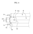
- Fig. 4 is top view of the first exemplary embodiment as shown in Fig. 3 .
- FIG. 5 is an exploded perspective view of the current collecting member and the plurality of electrode assemblies of the rechargeable battery as shown in Fig. 3 according to the first exemplary embodiment of the present invention, and
- FIG. 6 is a perspective view of the current collecting member according to the first exemplary embodiment of the present invention.
- the current collecting member 51 includes a terminal connection portion 512 fixed to the positive terminal 21, a side plate 517 formed bent from the terminal connection portion 512, and current collecting plates 513 and 515 fixed to the positive electrode uncoated region 11a.
- a fuse portion 512b having a smaller width than the periphery region is formed in the terminal connection portion 512.
- the side plate 517 is bent from the terminal connection portion 512 such that it is in parallel to the uncoated regions 11a of each of the electrode assemblies and bents from side surfaces of the terminal connection portion 512 formed in parallel to the uncoated regions 11a. In other words, side plate 517 is bent from a longitudinal side surface of the terminal connection portion 512 being formed in parallel to the long side of the battery case 30 or the long side of the electrode assembly 10.
- the current collecting member 52 formed in the negative terminal 22 is the same as the current collecting member 51 in structure, excluding the fuse portion 512b, a repeated description will be omitted.
- the terminal connection portion 512 is formed in the shape of a square plate, and a hole 512a to which the positive terminal 21 is inserted is formed in a center thereof. Further, the terminal connection portion 512 is welded to the lower portion of the positive terminal 21.
- the fuse portion 512b has a smaller width than the periphery region, and thus a hole 512c is formed in the fuse portion 512b.
- the hole 512c is extended along a width direction (y-axis direction in FIG. 5 ) of the terminal connection portion 512. Ends of lateral sides the terminal connection portion 512 are bent downward such that the terminal connection portion 512 has an arc-shaped cross-section and portions protruding downward are formed in the ends of the lateral sides of the terminal connection portion 512.
- the hole 512c is formed in a center of the terminal connection portion 512, and the protruded portions are also formed in the fuse portion 512b.
- the protruded portions support height directional stress of the current collecting member 51 so that breakage of the fuse portion 512b due to the fatigue stress can be prevented.
- the side plate 517 is perpendicularly bent toward the bottom of the case 30 from a width directional end of the terminal connection portion 512. Accordingly, the side plate 517 is disposed in parallel with the wide front side of the case 30.
- the side plate 517 is bent at a corner formed by being extended along a direction (x-axis direction) that crosses the direction (y-axis direction) along which the fuse portion 512b is extended.
- the direction along which the fuse portion 512b is extended and the corner where then side plate 517 is bent may be perpendicularly crossed.
- the fuse portion 512b When the side plate 517 is bent at a length directional end of the terminal connection portion 512, vertical directional stress applied to the fuse portion 512b is increased so that the fuse portion 512b may be broken due to vibration or impact. Thus, for stable strength of the fuse portion 512b, the fuse portion 512b should have a large width. However, when the fuse portion 512b has a large width, the fuse 512b may not be melted when the amount of current is insufficient even though the short-circuit occurred.
- the stress applied to the fuse portion 512b is decreased and thus the thickness of the fuse portion 512b can be reduced so that the fuse portion 512b can be activated with a small amount of current.
- a current collecting plate 515 is formed by being extended from a lower portion of the side plate 517, and a current collecting plate 513 is fixed to the current collecting plate 515 using supporting portions 516 and 518.
- the current collecting plates 513 and 515 are formed in the shape of a long square, and they are welded to the positive electrode uncoated region 11a.
- the supporting portion 516 is formed in upper portions of the current collecting plates 513 and 515 for connection therebetween in a fixed manner and the supporting portion 518 is formed in lower portions of the current collecting plates 513 and 515 for connection therebetween in a fixed manner.
- the supporting portion 516 provided in the upper portions of the current collecting plates 513 and 515 includes a connection portion 516a arranged opposite to the electrode assembly 10 and guiding portions 516b formed at lateral side ends of the connection portion 516a and then fixed to the current collecting plates 513 and 516.
- the guiding portions 516a are bent in the shape of an arc. Accordingly, the supporting portion 516 protrudes toward a direction (x-axis direction) facing the electrode assembly 10 from the current collecting plates 513 and 515.
- the connection portion 516a is formed in the shape of a square plate and the guiding plate 516b is formed of a curved plate having an arc-shaped cross-section.
- the supporting portion 518 provided in the lower portions of the current collecting plates 513 and 515 includes a connection portion 518a arranged opposite to the electrode assembly 10 and guiding portions 518b formed at lateral side ends of the connection portion 518a and fixed to the current collecting plates 513 and 515.
- the guiding portions 518b are bent in the shape of an arc. Accordingly, the supporting portion 518 protrudes toward a direction (x-axis) facing the electrode assembly 10 from the current collecting plates 513 and 515.
- the connection portion 518a is formed in the shape of a square plate
- the guiding portion 518b is formed of a curved plate having an arc-shaped cross-section.
- the uncoated region where the active material is not coated is thinner than the coated region where the active material is coated, and therefore an inclined face 10a is formed in a portion where the uncoated region and the coated region are connected.
- the guiding portions 516b and 518 contact the inclined face 10a formed in the electrode assembly 10 to prevent the electrode assembly 10 from moving due to impact and vibration. Movement of the electrode assembly 10 due to vibration may cause electrical contact failure between the current collecting member 51 and the positive electrode uncoated region 11a and electrical contact failure between the current collecting member 51 and the positive terminal 21. In addition, when the electrode assembly 10 is severally moved, the electrode assembly 10 contacts the case 30, thereby causing a short-circuit.
- the current collecting member 51 supports the electrode assembly 10 to prevent movement of the electrode assembly 10, and accordingly safety of the rechargeable battery 101 can be improved.
- the supporting portions 516 and 518 support the current collecting plates 513 and 515 to prevent the current collecting plates 513 and 515 from moving in a direction (y-axis direction) along which the electrode assembly 10 is layered.
- the electrical connection failure between the current collecting plates 513 and 515 and the positive electrode uncoated region 11a can be prevented.
- insulating members 55 and 57 are attached to portions facing the inside of the case 30.
- the current collecting member 51 includes a protrusion 56 protruding further to the outside than the current collecting plates 513 and 515 from the terminal connection portion 512 and the side plate 517.
- the insulating members 55 and 57 are formed as a tape type such that they are respectively attached to each end of the protrusion 56 and the current collecting plate 513.
- the insulating members 55 and 57 are provided to prevent short-circuit due to contact of the case 30 and the current collecting member 51.
- the insulating members 55 and 57 cover the side surfaces of the current collecting member 51 facing away from the electrode assembly 10 and facing toward an interior surface of the case 30. Furthermore, the uncoated regions 11a are in close contact with the current collecting plates, preferably they are arranged in direct physical contact parallel to each other.
- FIG. 7 is a perspective view of a current collecting member of a rechargeable battery according to a second exemplary embodiment of the present invention.
- the rechargeable battery according to the present exemplary embodiment is the same as the rechargeable battery of the first exemplary embodiment of the present invention, excluding a structure of a current collecting member 53, and therefore no repeated description will be provided.
- the current collecting member 53 includes a terminal connection portion 532 fixed to a positive terminal 21, a side plate 537 formed by being bent from the terminal connection portion 532, and current collecting plates 533 and 535 fixed to a positive electrode uncoated region 11a.
- a fuse portion 532b having a smaller width than the periphery region is formed.
- the current collecting member provided in a negative terminal 22 is the same as the current collecting member 53 in structure, excluding the fuse portion 532b, and therefore no repeated description will be provided.
- the terminal connection portion 532 is formed in the shape of a square plate, and a hole 532a to which the positive terminal 21 is inserted in formed in a center of the terminal connection portion 532. Further, the terminal connection portion 532 is welded to a lower portion of the positive terminal 21.
- the fuse portion 532b has a smaller width than the periphery region, and thus a hole 532c is formed in the fuse portion 532b.
- the hole 532c is formed extended to a side end of the terminal connection portion 532 from lateral side ends of the fuse portion 532b.
- the side plate 537 is perpendicularly bent toward the bottom of the case 30 from a width directional end of the terminal connection portion 532. Accordingly, the side plate 537 is disposed in parallel with a wide front side of the case 30.
- the side plate 537 is bent at a corner formed extended in a direction crossing a direction in which the fuse portion 512b is extended.
- the direction in which the fuse portion 532b is extended and the corner at which the side plate 537 is bent may be perpendicularly crossed with each other.
- the stress applied to the fuse 532b is decreased and thus the thickness of the fuse portion 532b may be decreased so that the fuse portion 532b may be activated with a small amount of current.
- the current collecting plates 535 is formed by being extended from a lower portion of the current collecting side plate 537, and a current collecting plate 533 is formed in the current collecting plate 535 in a fixed manner using the supporting portions 536 and 538.
- the current collecting plates 533 and 535 are formed in the shape of a long square plate, and they are welded to the positive electrode uncoated region 11a.
- the supporting portion 536 is formed in upper portions of the current collecting plates 533 and 535 for connection therebetween in a fixed manner and the supporting portion 538 is formed in lower portions of the current collecting plates 533 and 535 for connection therebetween in a fixed manner.
- the supporting portion 536 provided in the upper portions of the current collecting plates 533 and 535 includes a connection portion 536a arranged opposite to the electrode assembly 10 and guiding portions 536b formed at lateral side ends of the connection portion 536a and then fixed to the current collecting plates 533 and 536.
- the guiding portions 536a are bent in the shape of an arc.
- the supporting portion 536 protrudes toward a direction facing the electrode assembly 10 from the current collecting plates 533 and 535.
- the connection portion 536a is formed in the shape of a square plate and the guiding plate 536b is formed of a curved plate having an arc-shaped cross-section.
- the supporting portion 538 provided in the lower portions of the current collecting plates 533 and 535 includes a connection portion 538a arranged opposite to the electrode assembly 10 and guiding portions 538b formed at lateral side ends of the connection portion 538a and fixed to the current collecting plates 533 and 535.
- the guiding portions 538b are bent in the shape of an arc. Accordingly, the supporting portion 538 protrudes toward a direction facing the electrode assembly 10 from the current collecting plates 533 and 535.
- the connection portion 538a is formed in the shape of a square plate, and the guiding portion 538b is formed of a curved plate having an arc-shaped cross-section.
- an uncoated region where an active material is not coated is thinner than a coated region where the active material is coated, and therefore an inclined face 10a is formed in a portion where the uncoated region and the coated region are connected.
- the guiding portions 536b and 538 contact the inclined face 10a formed in the electrode assembly 10 to prevent the electrode assembly 10 from moving due to impact and vibration.
- FIG. 8 is a perspective view of a current collecting member of a rechargeable battery according to a third exemplary embodiment of the present invention.
- the rechargeable battery according to the present exemplary embodiment is the same as the rechargeable battery of the first exemplary embodiment of the present invention, excluding a structure of a current collecting member 61, and therefore no repeated description will be provided.
- the current collecting member 61 includes a terminal connection portion 612 fixed to a positive terminal 21, a side plate 617 formed by being bent from the terminal connection portion 612, and current collecting plates 613 and 615 fixed to a positive electrode uncoated region 11a.
- a fuse portion 612b having a smaller width than the periphery region is formed.
- the current collecting member provided in a negative terminal 22 is the same as the current collecting member 61 in structure, excluding the fuse portion 612b, and therefore no repeated description will be provided.
- the terminal connection portion 612 is formed in the shape of a square plate, and a hole 612a to which the positive terminal 21 is inserted in formed in a center of the terminal connection portion 612. Further, the terminal connection portion 612 is welded to a lower portion of the positive terminal 21.
- the fuse portion 612b has a smaller width than the periphery region, and thus a hole 612c is formed in the fuse portion 612b.
- the hole 612c is extended in a width direction of the terminal connection portion 612. Ends of lateral sides the terminal connection portion 612 are bent downward such that the terminal connection portion 612 has an arc-shaped cross-section and portions protruding downward are formed in the ends of the lateral sides of the terminal connection portion 612.
- the hole 612c is formed in a center of the terminal connection portion 612, and the protruded portions are also formed in the fuse portion 612b.
- the side plate 617 is perpendicularly curved toward the bottom of the case 30 from a width directional end of the terminal connection portion 612.
- the side plate 617 is disposed in parallel with a wide front side of the case 30.
- the side plate 617 is bent at a corner formed by being extended along a direction that crosses the direction along which the fuse portion 612b is extended.
- the direction along which the fuse portion 612b is extended and the corner where then side plate 617 is bent may be perpendicularly crossed.
- the stress applied to the fuse portion 612b is decreased and thus the thickness of the fuse portion 612b can be reduced so that the fuse portion 612b can be activated with a small amount of current.
- a current collecting plate 615 is formed by being extended from a lower portion of the side plate 617, and a current collecting plate 613 is fixed to the current collecting plate 615 using supporting portions 616 and 618.
- the current collecting plates 613 and 615 are formed in the shape of a long square, and they are welded to the positive electrode uncoated region 11a.
- the supporting portion 616 is formed in upper portions of the current collecting plates 613 and 615 for connection therebetween in a fixed manner and the supporting portion 618 is formed in lower portions of the current collecting plates 613 and 615 for connection therebetween in a fixed manner.
- the supporting portion 616 provided in the upper portions of the current collecting plates 613 and 615 includes a connection portion 616a disposed facing the electrode assembly 10 and extended in a direction toward the other current collecting plate 615 from one current collecting plate 613 and guiding portions 616b provided at lateral side ends of the connection portion 616a and fixed to the current collecting plates 613 and 615.
- the guiding portions 616b are inclined with respect to the connection portion 616a.
- the connection portion 616a is formed in the shape of a square plate, and the guiding portions 616b are inclined with respect to the current collecting plates 613 and 615 and the connection portion 616a.
- the supporting portion 618 provided in the lower portions of the current collecting plates 613 and 615 includes a connection portion 618a disposed facing the electrode assembly 10 and extended toward the other current collecting plate 615 from one current collecting plate 613 and guiding portions 618b provided at lateral side ends of the connection portion 618a and fixed to the current collecting plates 613 and 618.
- the guiding portions 618b are inclined with respect to the connection portion 618a.
- the supporting portion 618 is formed in the shape of a square plate, and the guiding portions 616b are inclined with respect to the current collecting plates 613 and 615 and the connection portion 616a.
- the connection portion 618a is formed in the shape of a square plate, and the guiding portions 618b are inclined with respect to the current collecting plates 613 and 615 and the connection portion 616a.
- an uncoated region where an active material is not coated is thinner than a coated region where the active material is coated, and therefore an inclined face 10a is formed in a portion where the uncoated region and the coated region are connected.
- the guiding portions 616b and 618b matches in parallel with the inclined face 10a formed in the electrode assembly 10 and contact the same.
- the guiding portions 616b and 618b support the electrode assembly 10 in the inclined face 10a to prevent the electrode assembly 10 from moving due to impact or vibration.
- the contact area between the guiding portions 616b and 681 b and the inclined face 10a is increased so that the guiding portions 616b and 618b can be further stably support the electrode assembly 10.
- FIG. 9 is a perspective view of a current collecting member of a rechargeable battery according to a fourth exemplary embodiment of the present invention.
- the rechargeable battery according to the present exemplary embodiment is the same as the rechargeable battery of the first exemplary embodiment of the present invention, excluding a structure of a current collecting member 62, and therefore no repeated description will be provided.
- the current collecting member 62 includes a terminal connection portion 622 fixed to a positive terminal 21, a side plate 627 formed by being bent from the terminal connection portion 622, and current collecting plates 623 and 625 fixed to a positive electrode uncoated region 11a.
- a fuse portion 622b having a smaller width than the periphery region is formed.
- the current collecting member provided in a negative terminal 22 is the same as the current collecting member 62 in structure, excluding the fuse portion 622b, and therefore no repeated description will be provided.
- the terminal connection portion 622 is formed in the shape of a square plate, and a hole 622a to which the positive terminal 21 is inserted in formed in a center of the terminal connection portion 622. Further, the terminal connection portion 622 is welded to a lower portion of the positive terminal 21.
- the fuse portion 622b has a smaller width than the periphery region, and thus a hole 622c is formed in the fuse portion 622b.
- the hole 622c is extended in a width direction of the terminal connection portion 622. Ends of lateral sides the terminal connection portion 622 are bent downward such that the terminal connection portion 622 has an arc-shaped cross-section and portions protruding downward are formed in the ends of the lateral sides of the terminal connection portion 622.
- the hole 622c is formed in a center of the terminal connection portion 622, and the protruded portions are also formed in the fuse portion 622b.
- the side plate 627 is perpendicularly curved toward the bottom of the case 30 from a width directional end of the terminal connection portion 622.
- the side plate 627 is disposed in parallel with a wide front side of the case 30.
- the side plate 627 is bent at a corner formed by being extended along a direction that crosses the direction along which the fuse portion 622b is extended.
- the direction along which the fuse portion 622b is extended and the corner where then side plate 627 is bent may be perpendicularly crossed.
- the stress applied to the fuse portion 622b is decreased and thus the thickness of the fuse portion 622b can be reduced so that the fuse portion 622b can be activated with a small amount of current.
- a current collecting plate 625 is formed by being extended from a lower portion of the side plate 627, and a current collecting plate 623 is fixed to the current collecting plate 625 using supporting portions 626 and 628.
- the current collecting plates 623 are formed in the shape of a long square plate, and includes a welding bar 623a welded to a positive electrode uncoated region 11a, a bent bar 623b formed in a lower portion of the welding bar 623a and bent toward the opposite current collecting plate 625, and an insertion tip 623c formed at an end portion of the bent bar 623b.
- the bent bar 623b is inclined in a direction to the outside from the center of the electrode assembly 10 to which the welding bar 623b is attached, and may be inclined with an angle of about 5° to 90° .
- the insertion tip 623c is formed at an end portion of the bent bar 623b and separated from the positive electrode uncoated region 11a.
- a distance between two facing insertion tips 623c is smaller than a distance between facing welding bars 623a.
- the insertion tip 623c is disposed further inside than the interface between the electrode assemblies 10 so that the facing insertion tips 625c do not contact.
- the current collecting member 62 can be easily inserted between the electrode assemblies 10 without causing damage to the positive electrode uncoated region 11a because the insertion is performed while the insertion tip 623c is being separated from the positive electrode uncoated region 11a.
- the welding bar 623a is designed to be closely attached to the positive electrode uncoated region 11a
- the insertion tip 623c is inserted while being separated from the positive electrode uncoated region 11a when the welding bar 623a presses the positive electrode uncoated region 11a so that the current collecting member 62 can be easily inserted.
- the current collecting member 62 is provided in a manner that makes the welding bar 623a press the positive electrode uncoated region 11a
- the welding bar 623a and the positive electrode uncoated region 11a are closely attached to each other so that a contact failure between the current collecting member 62 and the positive electrode uncoated region 11a due to external impact or vibration can be prevented.
- the current collecting plates 625 are formed in the shape of a long square plate, and includes a welding bar 625a welded to a positive electrode uncoated region 11a, a bent bar 625b formed in a lower portion of the welding bar 625a and bent toward the opposite current collecting plate 623, and an insertion tip 625c formed at an end portion of the bent bar 625b.
- the bent bar 625b is inclined in a direction to the outside from the center of the electrode assembly 10 to which the welding bar 625b is attached, and may be inclined with an angle of about 5° to 90°.
- the insertion tip 625c is formed at an end portion of the bent bar 625b and separated in the positive electrode uncoated region 11a.
- a distance between two facing insertion tips 625c is smaller than a distance between facing welding bars 625a.
- the insertion tip 625c is disposed further inside than the interface between the electrode assemblies 10 so that the facing insertion tips 623c do not contact.
- the current collecting member 62 can be easily inserted between the electrode assemblies 10 without causing damage to the positive electrode uncoated region 11a because the insertion is performed while the insertion tip 625c is being separated from the positive electrode uncoated region 11a.
- the welding bar 625a is designed to be closely attached to the positive electrode uncoated region 11a
- the insertion tip 625c is inserted while being separated from the positive electrode uncoated region 11a when the welding bar 625a presses the positive electrode uncoated region 11a so that the current collecting member 62 can be easily inserted.
- the current collecting member 62 is provided in a manner that makes the welding bar 625a press the positive electrode uncoated region 11a
- the welding bar 625a and the positive electrode uncoated region 11a are closely attached to each other so that a contact failure between the current collecting member 62 and the positive electrode uncoated region 11a due to external impact or vibration can be prevented.
- the supporting portion 626 is formed in upper portions of the current collecting plates 623 and 625 for connection therebetween in a fixed manner and the supporting portion 628 is formed in lower portions of the current collecting plates 623 and 625 for connection therebetween in a fixed manner.
- the supporting portions 626 and 628 are respectively provided in upper and lower portions of the welding bars 623a and 625a.
- FIG. 10 is a perspective view of a current collecting member of a rechargeable battery according to a fifth exemplary embodiment of the present invention.
- the rechargeable battery according to the present exemplary embodiment is the same as the rechargeable battery of the first exemplary embodiment of the present invention, excluding a structure of a current collecting member 63, and therefore no repeated description will be provided.
- the current collecting member 63 includes a terminal connection portion 632 fixed to a positive terminal 21, a side plate 637 formed by being bent from the terminal connection portion 632, and current collecting plates 633 and 635 fixed to a positive electrode uncoated region 11a.
- a fuse portion 632b having a smaller width than the periphery region is formed.
- the current collecting member provided in a negative terminal 22 is the same as the current collecting member 63 in structure, excluding the fuse portion 632b, and therefore no repeated description will be provided.
- the terminal connection portion 632 is formed in the shape of a square plate, and a hole 632a to which the positive terminal 21 is inserted in formed in a center of the terminal connection portion 632. Further, the terminal connection portion 632 is welded to a lower portion of the positive terminal 21.
- the fuse portion 632b has a smaller width than the periphery region, and thus a hole 632c is formed in the fuse portion 632b.
- the hole 63c is extended in a width direction of the terminal connection portion 632. Ends of lateral sides the terminal connection portion 632 are bent downward such that the terminal connection portion 632 has an arc-shaped cross-section and portions protruding downward are formed in the ends of the lateral sides of the terminal connection portion 632.
- the hole 632c is formed in a center of the terminal connection portion 632, and the protruded portions are also formed in the fuse portion 632b.
- the side plate 637 is perpendicularly curved toward the bottom of the case 30 from a width directional end of the terminal connection portion 632.
- the side plate 637 is disposed in parallel with a wide front side of the case 30.
- the side plate 637 is bent at a corner formed by being extended along a direction that crosses the direction along which the fuse portion 632b is extended.
- the direction along which the fuse portion 632b is extended and the corner where then side plate 637 is bent may be perpendicularly crossed.
- the stress applied to the fuse portion 632b is decreased and thus the thickness of the fuse portion 632b can be reduced so that the fuse portion 632b can be activated with a small amount of current.
- a current collecting plate 635 is formed by being extended from a lower portion of the side plate 637, and a current collecting plate 633 is fixed to the current collecting plate 635 using supporting portions 636 and 638.
- the current collecting plates 633 are formed in the shape of a long square plate, and includes a welding bar 633a welded to a positive electrode uncoated region 11a, a bent bar 633b formed in a lower portion of the welding bar 633a and bent toward the opposite current collecting plate 635, and an insertion tip 633c formed at an end portion of the bent bar 633b.
- the bent bar 633b is inclined in a direction to the outside from the center of the electrode assembly 10 to which the welding bar 633b is attached, and may be inclined with an angle of about 5° to 90°.
- the insertion tip 633c is formed at an end portion of the bent bar 633b and separated in the positive electrode uncoated region 11a.
- a distance between two facing insertion tips 633c is smaller than a distance between facing welding bars 633a.
- the insertion tip 633c is disposed further inside than the interface between the electrode assemblies 10 so that the facing insertion tips 633c do not contact.
- the current collecting member 63 can be easily inserted between the electrode assemblies 10 without causing damage to the positive electrode uncoated region 11a because the insertion is performed while the insertion tip 633c is being separated from the positive electrode uncoated region 11a.
- the welding bar 633a is designed to be closely attached to the positive electrode uncoated region 11a, the insertion tip 633c is inserted while being separated from the positive electrode uncoated region 11a when the welding bar 633a presses the positive electrode uncoated region 11a so that the current collecting member 63 can be easily inserted.
- the current collecting member 63 is provided in a manner that makes the welding bar 633a press the positive electrode uncoated region 11a, the welding bar 633a and the positive electrode uncoated region 11a are closely attached to each other so that a contact failure between the current collecting member 63 and the positive electrode uncoated region 11a due to external impact or vibration can be prevented.
- the current collecting plates 635 are formed in the shape of a long square plate, and includes a welding bar 635a welded to a positive electrode uncoated region 11a, a bent bar 635b formed in a lower portion of the welding bar 635a and bent toward the opposite current collecting plate 633, and an insertion tip 635c formed at an end portion of the bent bar 635b.
- the bent bar 635b is inclined in a direction to the outside from the center of the electrode assembly 10 to which the welding bar 635b is attached, and may be inclined with an angle of about 5° to 90°.
- the insertion tip 635c is formed at an end portion of the bent bar 635b and separated in the positive electrode uncoated region 11a.
- a distance between two facing insertion tips 635c is smaller than a distance between facing welding bars 635a.
- the insertion tip 635c is disposed further inside than the interface between the electrode assemblies 10 so that the facing insertion tips 633c do not contact.
- the current collecting member 63 can be easily inserted between the electrode assemblies 10 without causing damage to the positive electrode uncoated region 11a because the insertion is performed while the insertion tip 635c is being separated from the positive electrode uncoated region 11a.
- the welding bar 635a is designed to be closely attached to the positive electrode uncoated region 11a
- the insertion tip 635c is inserted while being separated from the positive electrode uncoated region 11a when the welding bar 635a presses the positive electrode uncoated region 11a so that the current collecting member 63 can be easily inserted.
- the current collecting member 63 is provided in a manner that makes the welding bar 635a press the positive electrode uncoated region 11a
- the welding bar 635a and the positive electrode uncoated region 11a are closely attached to each other so that a contact failure between the current collecting member 63 and the positive electrode uncoated region 11a due to external impact or vibration can be prevented.
- the supporting portion 636 is formed in upper portions of the current collecting plates 633 and 635 for connection therebetween in a fixed manner and the supporting portion 638 is formed in lower portions of the current collecting plates 633 and 635 for connection therebetween in a fixed manner.
- the supporting portion 636 is fixed to upper portions of the welding bars 623a and 625a, and the supporting portion 638 is fixed to the insertion tips 633c and 635c.
- the invention has been described with embodiments showing four electrode assemblies. However, the invention is not limited to this number.
- the current collecting members shown can be adopted to any number of electrode assemblies.
Landscapes
- Chemical & Material Sciences (AREA)
- Chemical Kinetics & Catalysis (AREA)
- Electrochemistry (AREA)
- General Chemical & Material Sciences (AREA)
- Engineering & Computer Science (AREA)
- Manufacturing & Machinery (AREA)
- Connection Of Batteries Or Terminals (AREA)
- Secondary Cells (AREA)
Abstract
a plurality of electrode assemblies each comprising a first electrode, a second electrode, and a separator interposed between the first and second electrodes, each electrode having a coated and an uncoated region, a case for mounting the plurality of electrode assemblies therein, a cap plate for closing an opening in the case, a first terminal protruding through the cap plate and being electrically coupled to a first current collecting member; the first current collecting member mechanically and electrically coupling each first electrode of the plurality of electrode assemblies to the first terminal; the first current collecting member further comprises: a plurality of current collecting plates, each current collecting plate being fixed to an uncoated region of one of the plurality of first electrodes, and a plurality of supporting portions connecting neighboring current collecting plates, wherein the first current collecting member comprises a terminal connection portion and a side plate extending from a lateral side surface of the terminal connection portion and electrically coupling the plurality of current collecting plates to the first terminal.
Description
- The described technology relates generally to a rechargeable battery. More particularly, the described technology relates generally to a rechargeable battery of which a current collecting member is improved in structure.
- A rechargeable battery can be repeatedly charged and discharged, unlike a primary battery that cannot be recharged.
- A low-capacity rechargeable battery is used for a small portable electronic device such as a mobile phone, a laptop computer, and a camcorder. A large-capacity rechargeable battery is widely used as a power supply for driving a motor of a hybrid vehicle and the like.
- Recently, a high-output rechargeable battery using a non-aqueous electrolyte solution with high energy density has been developed. The high-output rechargeable battery is configured of a large-capacity battery module in which a plurality of rechargeable batteries are connected to each other in series so as to be used to drive a motor of devices requiring large power, for example, an electric car, or the like.
- The battery module is generally configured by the plurality of rechargeable batteries that are coupled with each other in series, and each of the rechargeable batteries may be formed in a cylindrical shape, a prismatic shape, and the like.
- The above information disclosed in this Background section is only for enhancement of understanding of the background of the described technology and therefore it may contain information that does not form the prior art that is already known in this country to a person of ordinary skill in the art.
- The described technology has been made in an effort to provide a rechargeable battery improved in safety.
- A rechargeable battery according to an exemplary embodiment includes
a plurality of electrode assemblies each comprising a first electrode, a second electrode, and a separator interposed between the first and second electrodes, each electrode having a coated and an uncoated region, a case for mounting the plurality of electrode assemblies therein, a cap plate for closing an opening in the case, a first terminal protruding through the cap plate and being electrically coupled to a first current collecting member; the first current collecting member mechanically and electrically coupling each first electrode of the plurality of electrode assemblies to the first terminal; the first current collecting member further comprises: a plurality of current collecting plates, each current collecting plate being fixed to an uncoated region of one of the plurality of first electrodes, and a plurality of supporting portions connecting neighboring current collecting plates, wherein the first current collecting member comprises a terminal connection portion and a side plate extending from a lateral side surface of the terminal connection portion and electrically coupling the plurality of current collecting plates to the first terminal. - The terminal connection portion preferably comprises a fuse portion and the side plate is bent from a side formed by being extended along a direction that crosses a width direction along which the fuse portion is extended. The side where the side plate is bent from is preferably disposed at an end of the fuse portion and/or wherein a lateral projection of the fuse portion and the side plate overlaps.
- A first current collecting plate preferably extends from a lower surface of the side plate.
- Preferably, a second current collecting plate is connected to the first current collecting plate via at least one supporting portion, preferably two supporting portions.
- A first supporting portion may be formed in an upper portion of the first current collecting plate and/or a second supporting portion may be formed in the lower portion of the first current collecting plate.
- The first or second supporting portion preferably comprises a connection portion extending from a side surface of the first current collecting member facing away from the plurality of electrode assemblies; and a guiding portion formed extending from the connection portion to the second current collecting plate.
- Each first electrode comprises an inclined surface between its uncoated and its coated region, the guiding portion being in physical contact with the inclined surface. In other words, the guiding portion is in directed contact with the inclined surface. The guiding portions are preferably inclined with respect to the connection portion to closely attach to the inclined surface.
- A current collecting plate may have a stepped profile with a welding bar and a bent bar formed at a lower end of welding bar and being inclined with respect to the welding bar, and an insertion tip formed at an end portion of the bent bar such that the insertion tip is not in contact with the first electrode. Preferably, the bent bar is inclined with an angle between 5° and 90° with respect to welding bar, more preferably below 90°.
- The shortest distance between two adjacent welding bars is preferably greater than the shortest distance between two adjacent insertion tips.
- A supporting portion may connect two adjacent insertion tips.
- Insulating members are attached to portions of the first current collecting member facing the inside of the case.
- The side plate may comprise a protrusion such that the width of the side plate is larger than the width of the current collecting plates.
- According to the exemplary embodiment, the supporting portion supports movement of the electrode assembly due to impact or vibration so that a short-circuit between the electrode assembly and the case can be prevented.
-
-
FIG. 1 is a perspective view of a rechargeable battery according to a first exemplary embodiment of the present invention. -
FIG. 2 is a cross-sectional view ofFIG. 1 , taken along the line 11-11. -
FIG. 3 is a perspective view of a current collecting member and a plurality of electrode assemblies of the rechargeable battery according to the first exemplary embodiment of the present invention. -
Fig. 4 is top view of the first exemplary embodiment as shown inFig. 3 . -
FIG. 5 is an exploded perspective view of a current collecting member and a plurality of electrode assemblies of the rechargeable battery according to the first exemplary embodiment of the present invention. -
FIG. 6 is a perspective view of the current collecting member according to the first exemplary embodiment of the present invention. -
FIG. 7 is a perspective view of a current collecting member of a rechargeable battery according to a second exemplary embodiment of the present invention. -
FIG. 8 is a perspective view of a current collecting member of a rechargeable battery according to a third exemplary embodiment of the present invention. -
FIG. 9 is a perspective view of a current collecting member of a rechargeable battery according to a fourth exemplary embodiment of the present invention. -
FIG. 10 is a perspective view of a current collecting member of a rechargeable battery according to a fifth exemplary embodiment of the present invention. - The present invention will be described more fully hereinafter with reference to the accompanying drawings, in which exemplary embodiments of the invention are shown. As those skilled in the art would realize, the described embodiments may be modified in various different ways, all without departing from the scope of the present invention. Like reference numerals designate like elements throughout the specification and the drawings.
-
FIG. 1 is a perspective view of a rechargeable battery according to a first exemplary embodiment of the present invention andFIG. 2 is a cross-sectional view ofFIG. 1 , taken along the line 11-11. - Referring to
FIG. 1 andFIG. 2 , arechargeable battery 101 according to the first exemplary embodiment includes a plurality ofelectrode assemblies 10 formed by winding apositive electrode 11 and anegative electrode 12, interposing aseparator 13 therebetween, acase 30 in which theelectrode assembly 10 is installed, and acap assembly 20 coupled to an opening of thecase 30. - The
rechargeable battery 101 according to the first exemplary embodiment is exemplarily described as a lithium ion secondary battery formed in the shape of a prism. However, the present invention is not limited thereof, and the present invention may be applied to various shapes of batteries such as a lithium polymer battery or a cylindrical battery. - The
positive electrode 11 and thenegative electrode 12 include coated regions where an active material is coated to a current collector formed of a thin metal foil anduncoated regions - The positive electrode
uncoated region 11a is formed at a first side end of thepositive electrode 11 along a length direction of thepositive electrode 11, and the negativeuncoated region 12a is formed at a second side end of thenegative electrode 12 along a length direction of thenegative electrode 12. Thepositive electrode 11 and thenegative electrode 12 are spirally wound, interposing theseparator 13 therebetween. Here, theseparator 13 is an insulator. - However, the present invention is not limited thereto, and the
electrode assembly 10 may have a structure where a positive electrode and a negative electrode, each formed of a plurality of sheets are alternately layered, interposing a separator therebetween. - The
case 30 is approximately formed in the shape of a cuboid, and an opening is formed one side thereof. Thecap assembly 20 includes acap plate 25 covering the opening of thecase 30, apositive terminal 21 protruding to an outer side of thecap plate 25 and electrically connected with thepositive electrode 11, anegative terminal 22 protruding to an outer side of thecap plate 25 and electrically connected with thenegative electrode 12, and avent member 27 having anotch 27a formed to be broken according to a predetermined internal pressure. - The
cap plate 25 is formed of a thin plate, and an electrolyte injection opening is formed at one side for injection of an electrolyte solution and a sealingcap 23 is fixed to thecap plate 25 to seal the electrolyte injection opening. - Since the
positive terminal 21 is formed penetrating thecap plate 25, afirst gasket 24 formed in an upper portion of thecap plate 25 and asecond gasket 26 formed in a lower portion of theca plate 25 insulate thecap plate 25 and thepositive terminal 21. - The
positive terminal 21 is formed in the shape of a circular cylinder, anut 29 is formed in thepositive terminal 21 to support thepositive terminal 21 from an upper portion and a thread is formed in an external circumference of thepositive terminal 21 so as to be fastened with thenut 29. - The
positive terminal 21 is electrically connected with the positive electrodeuncoated region 11a through acurrent collecting member 51, and a terminal flange that supports thepositive terminal 21 and thecurrent collecting member 51 is formed in a lower end of thepositive terminal 21. - Since the
negative terminal 22 is formed penetrating thecap plate 25, afirst gasket 24 formed in an upper portion of thecap plate 25 and asecond gasket 25 formed in a lower portion of thecap plate 25 insulate thecap plate 25 and thenegative terminal 22. - The
negative terminal 22 is formed in the shape of a circular cylinder, and anut 29 is formed in thenegative terminal 22 to support thenegative terminal 22 from an upper portion thereof and a thread is formed in an external circumference of thenegative terminal 22 so as to be fastened with thenut 29. - The
negative terminal 22 is electrically connected with the negative electrodeuncoated region 12a through acurrent collecting member 52, and a terminal flange is formed in a lower end of thenegative terminal 22 to support thenegative terminal 22 and thecurrent collecting member 52. -
FIG. 3 is a perspective view of a current collecting member and a pluralities of electrode assemblies of the rechargeable battery according to the first exemplary embodiment of the present invention.Fig. 4 is top view of the first exemplary embodiment as shown inFig. 3 .FIG. 5 is an exploded perspective view of the current collecting member and the plurality of electrode assemblies of the rechargeable battery as shown inFig. 3 according to the first exemplary embodiment of the present invention, andFIG. 6 is a perspective view of the current collecting member according to the first exemplary embodiment of the present invention. - Referring to
FIG. 3 ,4 5 andFIG. 6 , the current collectingmember 51 includes aterminal connection portion 512 fixed to thepositive terminal 21, aside plate 517 formed bent from theterminal connection portion 512, andcurrent collecting plates uncoated region 11a. Afuse portion 512b having a smaller width than the periphery region is formed in theterminal connection portion 512. Theside plate 517 is bent from theterminal connection portion 512 such that it is in parallel to theuncoated regions 11a of each of the electrode assemblies and bents from side surfaces of theterminal connection portion 512 formed in parallel to theuncoated regions 11a. In other words,side plate 517 is bent from a longitudinal side surface of theterminal connection portion 512 being formed in parallel to the long side of thebattery case 30 or the long side of theelectrode assembly 10. - Since the current collecting
member 52 formed in thenegative terminal 22 is the same as the current collectingmember 51 in structure, excluding thefuse portion 512b, a repeated description will be omitted. - The
terminal connection portion 512 is formed in the shape of a square plate, and ahole 512a to which thepositive terminal 21 is inserted is formed in a center thereof. Further, theterminal connection portion 512 is welded to the lower portion of thepositive terminal 21. Thefuse portion 512b has a smaller width than the periphery region, and thus ahole 512c is formed in thefuse portion 512b. Thehole 512c is extended along a width direction (y-axis direction inFIG. 5 ) of theterminal connection portion 512. Ends of lateral sides theterminal connection portion 512 are bent downward such that theterminal connection portion 512 has an arc-shaped cross-section and portions protruding downward are formed in the ends of the lateral sides of theterminal connection portion 512. Thehole 512c is formed in a center of theterminal connection portion 512, and the protruded portions are also formed in thefuse portion 512b. As in the present exemplary embodiment, when the portions protruding downward are formed in the ends of the lateral sides of theterminal connection portion 512, the protruded portions support height directional stress of the current collectingmember 51 so that breakage of thefuse portion 512b due to the fatigue stress can be prevented. - The
side plate 517 is perpendicularly bent toward the bottom of thecase 30 from a width directional end of theterminal connection portion 512. Accordingly, theside plate 517 is disposed in parallel with the wide front side of thecase 30. - That is, the
side plate 517 is bent at a corner formed by being extended along a direction (x-axis direction) that crosses the direction (y-axis direction) along which thefuse portion 512b is extended. The direction along which thefuse portion 512b is extended and the corner where thenside plate 517 is bent may be perpendicularly crossed. - When the
side plate 517 is bent at a length directional end of theterminal connection portion 512, vertical directional stress applied to thefuse portion 512b is increased so that thefuse portion 512b may be broken due to vibration or impact. Thus, for stable strength of thefuse portion 512b, thefuse portion 512b should have a large width. However, when thefuse portion 512b has a large width, thefuse 512b may not be melted when the amount of current is insufficient even though the short-circuit occurred. - However, when the
side plate 517 is formed in the width directional end of theterminal connection portion 512 as in the present exemplary embodiment, the stress applied to thefuse portion 512b is decreased and thus the thickness of thefuse portion 512b can be reduced so that thefuse portion 512b can be activated with a small amount of current. - A
current collecting plate 515 is formed by being extended from a lower portion of theside plate 517, and acurrent collecting plate 513 is fixed to thecurrent collecting plate 515 using supportingportions current collecting plates uncoated region 11a. - The supporting
portion 516 is formed in upper portions of thecurrent collecting plates portion 518 is formed in lower portions of thecurrent collecting plates - The supporting
portion 516 provided in the upper portions of thecurrent collecting plates connection portion 516a arranged opposite to theelectrode assembly 10 and guidingportions 516b formed at lateral side ends of theconnection portion 516a and then fixed to thecurrent collecting plates portions 516a are bent in the shape of an arc. Accordingly, the supportingportion 516 protrudes toward a direction (x-axis direction) facing theelectrode assembly 10 from thecurrent collecting plates connection portion 516a is formed in the shape of a square plate and the guidingplate 516b is formed of a curved plate having an arc-shaped cross-section. - The supporting
portion 518 provided in the lower portions of thecurrent collecting plates connection portion 518a arranged opposite to theelectrode assembly 10 and guidingportions 518b formed at lateral side ends of theconnection portion 518a and fixed to thecurrent collecting plates portions 518b are bent in the shape of an arc. Accordingly, the supportingportion 518 protrudes toward a direction (x-axis) facing theelectrode assembly 10 from thecurrent collecting plates connection portion 518a is formed in the shape of a square plate, and the guidingportion 518b is formed of a curved plate having an arc-shaped cross-section. - In the
electrode assembly 10, the uncoated region where the active material is not coated is thinner than the coated region where the active material is coated, and therefore aninclined face 10a is formed in a portion where the uncoated region and the coated region are connected. - The guiding
portions inclined face 10a formed in theelectrode assembly 10 to prevent theelectrode assembly 10 from moving due to impact and vibration. Movement of theelectrode assembly 10 due to vibration may cause electrical contact failure between the current collectingmember 51 and the positive electrodeuncoated region 11a and electrical contact failure between the current collectingmember 51 and thepositive terminal 21. In addition, when theelectrode assembly 10 is severally moved, theelectrode assembly 10 contacts thecase 30, thereby causing a short-circuit. - However, according to the present exemplary embodiment, the current collecting
member 51 supports theelectrode assembly 10 to prevent movement of theelectrode assembly 10, and accordingly safety of therechargeable battery 101 can be improved. - Further, the supporting
portions current collecting plates current collecting plates electrode assembly 10 is layered. Thus, the electrical connection failure between thecurrent collecting plates uncoated region 11a can be prevented. - In the current collecting
member 51, insulatingmembers case 30. The current collectingmember 51 includes aprotrusion 56 protruding further to the outside than thecurrent collecting plates terminal connection portion 512 and theside plate 517. The insulatingmembers protrusion 56 and thecurrent collecting plate 513. - As in the present exemplary embodiment, the insulating
members case 30 and the current collectingmember 51. - As can be seen from
Fig. 4 , the insulatingmembers member 51 facing away from theelectrode assembly 10 and facing toward an interior surface of thecase 30. Furthermore, theuncoated regions 11a are in close contact with the current collecting plates, preferably they are arranged in direct physical contact parallel to each other. -
FIG. 7 is a perspective view of a current collecting member of a rechargeable battery according to a second exemplary embodiment of the present invention. - The rechargeable battery according to the present exemplary embodiment is the same as the rechargeable battery of the first exemplary embodiment of the present invention, excluding a structure of a current collecting
member 53, and therefore no repeated description will be provided. - Referring to
FIG. 7 , the current collectingmember 53 includes aterminal connection portion 532 fixed to apositive terminal 21, aside plate 537 formed by being bent from theterminal connection portion 532, andcurrent collecting plates uncoated region 11a. In theterminal connection portion 532, afuse portion 532b having a smaller width than the periphery region is formed. - The current collecting member provided in a
negative terminal 22 is the same as the current collectingmember 53 in structure, excluding thefuse portion 532b, and therefore no repeated description will be provided. - The
terminal connection portion 532 is formed in the shape of a square plate, and ahole 532a to which thepositive terminal 21 is inserted in formed in a center of theterminal connection portion 532. Further, theterminal connection portion 532 is welded to a lower portion of thepositive terminal 21. Thefuse portion 532b has a smaller width than the periphery region, and thus ahole 532c is formed in thefuse portion 532b. Thehole 532c is formed extended to a side end of theterminal connection portion 532 from lateral side ends of thefuse portion 532b. - The
side plate 537 is perpendicularly bent toward the bottom of thecase 30 from a width directional end of theterminal connection portion 532. Accordingly, theside plate 537 is disposed in parallel with a wide front side of thecase 30. - That is, the
side plate 537 is bent at a corner formed extended in a direction crossing a direction in which thefuse portion 512b is extended. The direction in which thefuse portion 532b is extended and the corner at which theside plate 537 is bent may be perpendicularly crossed with each other. - When the
side plate 537 is bent at a length directional end of theterminal connection portion 532, a vertical directional stress applied to thefuse portion 532b is increased so that thefuse portion 532b may be broken due to vibration or impact. - However, when the
side plate 537 is formed in the width directional end of theterminal connection portion 532 as in the present exemplary embodiment, the stress applied to thefuse 532b is decreased and thus the thickness of thefuse portion 532b may be decreased so that thefuse portion 532b may be activated with a small amount of current. - The
current collecting plates 535 is formed by being extended from a lower portion of the current collectingside plate 537, and acurrent collecting plate 533 is formed in thecurrent collecting plate 535 in a fixed manner using the supportingportions current collecting plates uncoated region 11a. - The supporting
portion 536 is formed in upper portions of thecurrent collecting plates portion 538 is formed in lower portions of thecurrent collecting plates - The supporting
portion 536 provided in the upper portions of thecurrent collecting plates connection portion 536a arranged opposite to theelectrode assembly 10 and guidingportions 536b formed at lateral side ends of theconnection portion 536a and then fixed to thecurrent collecting plates portions 536a are bent in the shape of an arc. Thus, the supportingportion 536 protrudes toward a direction facing theelectrode assembly 10 from thecurrent collecting plates connection portion 536a is formed in the shape of a square plate and the guidingplate 536b is formed of a curved plate having an arc-shaped cross-section. - The supporting
portion 538 provided in the lower portions of thecurrent collecting plates connection portion 538a arranged opposite to theelectrode assembly 10 and guidingportions 538b formed at lateral side ends of theconnection portion 538a and fixed to thecurrent collecting plates portions 538b are bent in the shape of an arc. Accordingly, the supportingportion 538 protrudes toward a direction facing theelectrode assembly 10 from thecurrent collecting plates connection portion 538a is formed in the shape of a square plate, and the guidingportion 538b is formed of a curved plate having an arc-shaped cross-section. - In the
electrode assembly 10, an uncoated region where an active material is not coated is thinner than a coated region where the active material is coated, and therefore aninclined face 10a is formed in a portion where the uncoated region and the coated region are connected. - The guiding
portions inclined face 10a formed in theelectrode assembly 10 to prevent theelectrode assembly 10 from moving due to impact and vibration. -
FIG. 8 is a perspective view of a current collecting member of a rechargeable battery according to a third exemplary embodiment of the present invention. - The rechargeable battery according to the present exemplary embodiment is the same as the rechargeable battery of the first exemplary embodiment of the present invention, excluding a structure of a current collecting
member 61, and therefore no repeated description will be provided. - Referring to
FIG. 8 , the current collectingmember 61 includes aterminal connection portion 612 fixed to apositive terminal 21, aside plate 617 formed by being bent from theterminal connection portion 612, andcurrent collecting plates uncoated region 11a. In theterminal connection portion 612, afuse portion 612b having a smaller width than the periphery region is formed. - The current collecting member provided in a
negative terminal 22 is the same as the current collectingmember 61 in structure, excluding thefuse portion 612b, and therefore no repeated description will be provided. - The
terminal connection portion 612 is formed in the shape of a square plate, and ahole 612a to which thepositive terminal 21 is inserted in formed in a center of theterminal connection portion 612. Further, theterminal connection portion 612 is welded to a lower portion of thepositive terminal 21. Thefuse portion 612b has a smaller width than the periphery region, and thus ahole 612c is formed in thefuse portion 612b. Thehole 612c is extended in a width direction of theterminal connection portion 612. Ends of lateral sides theterminal connection portion 612 are bent downward such that theterminal connection portion 612 has an arc-shaped cross-section and portions protruding downward are formed in the ends of the lateral sides of theterminal connection portion 612. Thehole 612c is formed in a center of theterminal connection portion 612, and the protruded portions are also formed in thefuse portion 612b. - Meanwhile, the
side plate 617 is perpendicularly curved toward the bottom of thecase 30 from a width directional end of theterminal connection portion 612. Thus, theside plate 617 is disposed in parallel with a wide front side of thecase 30. - That is, the
side plate 617 is bent at a corner formed by being extended along a direction that crosses the direction along which thefuse portion 612b is extended. The direction along which thefuse portion 612b is extended and the corner where thenside plate 617 is bent may be perpendicularly crossed. - When the
side plate 617 is bent at a length directional end of theterminal connection portion 612, vertical directional stress applied to thefuse portion 612b is increased so that thefuse portion 612b may be broken due to vibration or impact. - However, when the
side plate 617 is formed in the width directional end of theterminal connection portion 612 as in the present exemplary embodiment, the stress applied to thefuse portion 612b is decreased and thus the thickness of thefuse portion 612b can be reduced so that thefuse portion 612b can be activated with a small amount of current. - A
current collecting plate 615 is formed by being extended from a lower portion of theside plate 617, and acurrent collecting plate 613 is fixed to thecurrent collecting plate 615 using supportingportions current collecting plates uncoated region 11a. - The supporting
portion 616 is formed in upper portions of thecurrent collecting plates portion 618 is formed in lower portions of thecurrent collecting plates - The supporting
portion 616 provided in the upper portions of thecurrent collecting plates connection portion 616a disposed facing theelectrode assembly 10 and extended in a direction toward the othercurrent collecting plate 615 from onecurrent collecting plate 613 and guidingportions 616b provided at lateral side ends of theconnection portion 616a and fixed to thecurrent collecting plates portions 616b are inclined with respect to theconnection portion 616a. Thus, the supportingportion 616 protrudes toward a direction facing theelectrode assembly 10 from thecurrent collecting plates connection portion 616a is formed in the shape of a square plate, and the guidingportions 616b are inclined with respect to thecurrent collecting plates connection portion 616a. - The supporting
portion 618 provided in the lower portions of thecurrent collecting plates connection portion 618a disposed facing theelectrode assembly 10 and extended toward the othercurrent collecting plate 615 from onecurrent collecting plate 613 and guidingportions 618b provided at lateral side ends of theconnection portion 618a and fixed to thecurrent collecting plates portions 618b are inclined with respect to theconnection portion 618a. The supportingportion 618 is formed in the shape of a square plate, and the guidingportions 616b are inclined with respect to thecurrent collecting plates connection portion 616a. Theconnection portion 618a is formed in the shape of a square plate, and the guidingportions 618b are inclined with respect to thecurrent collecting plates connection portion 616a. - In the
electrode assembly 10, an uncoated region where an active material is not coated is thinner than a coated region where the active material is coated, and therefore aninclined face 10a is formed in a portion where the uncoated region and the coated region are connected. - The guiding
portions inclined face 10a formed in theelectrode assembly 10 and contact the same. The guidingportions electrode assembly 10 in theinclined face 10a to prevent theelectrode assembly 10 from moving due to impact or vibration. According to the present exemplary embodiment, the contact area between the guidingportions 616b and 681 b and theinclined face 10a is increased so that the guidingportions electrode assembly 10. -
FIG. 9 is a perspective view of a current collecting member of a rechargeable battery according to a fourth exemplary embodiment of the present invention. - The rechargeable battery according to the present exemplary embodiment is the same as the rechargeable battery of the first exemplary embodiment of the present invention, excluding a structure of a current collecting
member 62, and therefore no repeated description will be provided. - Referring to
FIG. 9 , the current collectingmember 62 includes aterminal connection portion 622 fixed to apositive terminal 21, aside plate 627 formed by being bent from theterminal connection portion 622, andcurrent collecting plates uncoated region 11a. In theterminal connection portion 622, afuse portion 622b having a smaller width than the periphery region is formed. - The current collecting member provided in a
negative terminal 22 is the same as the current collectingmember 62 in structure, excluding thefuse portion 622b, and therefore no repeated description will be provided. - The
terminal connection portion 622 is formed in the shape of a square plate, and ahole 622a to which thepositive terminal 21 is inserted in formed in a center of theterminal connection portion 622. Further, theterminal connection portion 622 is welded to a lower portion of thepositive terminal 21. Thefuse portion 622b has a smaller width than the periphery region, and thus ahole 622c is formed in thefuse portion 622b. Thehole 622c is extended in a width direction of theterminal connection portion 622. Ends of lateral sides theterminal connection portion 622 are bent downward such that theterminal connection portion 622 has an arc-shaped cross-section and portions protruding downward are formed in the ends of the lateral sides of theterminal connection portion 622. Thehole 622c is formed in a center of theterminal connection portion 622, and the protruded portions are also formed in thefuse portion 622b. - Meanwhile, the
side plate 627 is perpendicularly curved toward the bottom of thecase 30 from a width directional end of theterminal connection portion 622. Thus, theside plate 627 is disposed in parallel with a wide front side of thecase 30. - That is, the
side plate 627 is bent at a corner formed by being extended along a direction that crosses the direction along which thefuse portion 622b is extended. The direction along which thefuse portion 622b is extended and the corner where thenside plate 627 is bent may be perpendicularly crossed. - When the
side plate 627 is bent at a length directional end of theterminal connection portion 622, vertical directional stress applied to thefuse portion 622b is increased so that thefuse portion 622b may be broken due to vibration or impact. - However, when the
side plate 627 is formed in the width directional end of theterminal connection portion 622 as in the present exemplary embodiment, the stress applied to thefuse portion 622b is decreased and thus the thickness of thefuse portion 622b can be reduced so that thefuse portion 622b can be activated with a small amount of current. - A
current collecting plate 625 is formed by being extended from a lower portion of theside plate 627, and acurrent collecting plate 623 is fixed to thecurrent collecting plate 625 using supportingportions - The
current collecting plates 623 are formed in the shape of a long square plate, and includes awelding bar 623a welded to a positive electrodeuncoated region 11a, abent bar 623b formed in a lower portion of thewelding bar 623a and bent toward the oppositecurrent collecting plate 625, and aninsertion tip 623c formed at an end portion of thebent bar 623b. Thebent bar 623b is inclined in a direction to the outside from the center of theelectrode assembly 10 to which thewelding bar 623b is attached, and may be inclined with an angle of about 5° to 90° . Theinsertion tip 623c is formed at an end portion of thebent bar 623b and separated from the positive electrodeuncoated region 11a. Thus, a distance between two facinginsertion tips 623c is smaller than a distance between facingwelding bars 623a. However, theinsertion tip 623c is disposed further inside than the interface between theelectrode assemblies 10 so that the facinginsertion tips 625c do not contact. - Thus, the current collecting
member 62 can be easily inserted between theelectrode assemblies 10 without causing damage to the positive electrodeuncoated region 11a because the insertion is performed while theinsertion tip 623c is being separated from the positive electrodeuncoated region 11a. - Further, since the
welding bar 623a is designed to be closely attached to the positive electrodeuncoated region 11a, theinsertion tip 623c is inserted while being separated from the positive electrodeuncoated region 11a when thewelding bar 623a presses the positive electrodeuncoated region 11a so that the current collectingmember 62 can be easily inserted. As described, when the current collectingmember 62 is provided in a manner that makes thewelding bar 623a press the positive electrodeuncoated region 11a, thewelding bar 623a and the positive electrodeuncoated region 11a are closely attached to each other so that a contact failure between the current collectingmember 62 and the positive electrodeuncoated region 11a due to external impact or vibration can be prevented. - The
current collecting plates 625 are formed in the shape of a long square plate, and includes awelding bar 625a welded to a positive electrodeuncoated region 11a, abent bar 625b formed in a lower portion of thewelding bar 625a and bent toward the oppositecurrent collecting plate 623, and aninsertion tip 625c formed at an end portion of thebent bar 625b. Thebent bar 625b is inclined in a direction to the outside from the center of theelectrode assembly 10 to which thewelding bar 625b is attached, and may be inclined with an angle of about 5° to 90°. Theinsertion tip 625c is formed at an end portion of thebent bar 625b and separated in the positive electrodeuncoated region 11a. Thus, a distance between two facinginsertion tips 625c is smaller than a distance between facingwelding bars 625a. However, theinsertion tip 625c is disposed further inside than the interface between theelectrode assemblies 10 so that the facinginsertion tips 623c do not contact. - Thus, the current collecting
member 62 can be easily inserted between theelectrode assemblies 10 without causing damage to the positive electrodeuncoated region 11a because the insertion is performed while theinsertion tip 625c is being separated from the positive electrodeuncoated region 11a. - Further, since the
welding bar 625a is designed to be closely attached to the positive electrodeuncoated region 11a, theinsertion tip 625c is inserted while being separated from the positive electrodeuncoated region 11a when thewelding bar 625a presses the positive electrodeuncoated region 11a so that the current collectingmember 62 can be easily inserted. As described, when the current collectingmember 62 is provided in a manner that makes thewelding bar 625a press the positive electrodeuncoated region 11a, thewelding bar 625a and the positive electrodeuncoated region 11a are closely attached to each other so that a contact failure between the current collectingmember 62 and the positive electrodeuncoated region 11a due to external impact or vibration can be prevented. - The supporting
portion 626 is formed in upper portions of thecurrent collecting plates portion 628 is formed in lower portions of thecurrent collecting plates portions welding bars -
FIG. 10 is a perspective view of a current collecting member of a rechargeable battery according to a fifth exemplary embodiment of the present invention. - The rechargeable battery according to the present exemplary embodiment is the same as the rechargeable battery of the first exemplary embodiment of the present invention, excluding a structure of a current collecting
member 63, and therefore no repeated description will be provided. - Referring to
FIG. 10 , the current collectingmember 63 includes aterminal connection portion 632 fixed to apositive terminal 21, aside plate 637 formed by being bent from theterminal connection portion 632, and current collecting plates 633 and 635 fixed to a positive electrodeuncoated region 11a. In theterminal connection portion 632, afuse portion 632b having a smaller width than the periphery region is formed. - The current collecting member provided in a
negative terminal 22 is the same as the current collectingmember 63 in structure, excluding thefuse portion 632b, and therefore no repeated description will be provided. - The
terminal connection portion 632 is formed in the shape of a square plate, and ahole 632a to which thepositive terminal 21 is inserted in formed in a center of theterminal connection portion 632. Further, theterminal connection portion 632 is welded to a lower portion of thepositive terminal 21. Thefuse portion 632b has a smaller width than the periphery region, and thus ahole 632c is formed in thefuse portion 632b. The hole 63c is extended in a width direction of theterminal connection portion 632. Ends of lateral sides theterminal connection portion 632 are bent downward such that theterminal connection portion 632 has an arc-shaped cross-section and portions protruding downward are formed in the ends of the lateral sides of theterminal connection portion 632. Thehole 632c is formed in a center of theterminal connection portion 632, and the protruded portions are also formed in thefuse portion 632b. - Meanwhile, the
side plate 637 is perpendicularly curved toward the bottom of thecase 30 from a width directional end of theterminal connection portion 632. Thus, theside plate 637 is disposed in parallel with a wide front side of thecase 30. - That is, the
side plate 637 is bent at a corner formed by being extended along a direction that crosses the direction along which thefuse portion 632b is extended. The direction along which thefuse portion 632b is extended and the corner where thenside plate 637 is bent may be perpendicularly crossed. - When the
side plate 637 is bent at a length directional end of theterminal connection portion 632, vertical directional stress applied to thefuse portion 632b is increased so that thefuse portion 632b may be broken due to vibration or impact. - However, when the
side plate 637 is formed in the width directional end of theterminal connection portion 632 as in the present exemplary embodiment, the stress applied to thefuse portion 632b is decreased and thus the thickness of thefuse portion 632b can be reduced so that thefuse portion 632b can be activated with a small amount of current. - A current collecting plate 635 is formed by being extended from a lower portion of the
side plate 637, and a current collecting plate 633 is fixed to the current collecting plate 635 using supportingportions - The current collecting plates 633 are formed in the shape of a long square plate, and includes a
welding bar 633a welded to a positive electrodeuncoated region 11a, abent bar 633b formed in a lower portion of thewelding bar 633a and bent toward the opposite current collecting plate 635, and aninsertion tip 633c formed at an end portion of thebent bar 633b. Thebent bar 633b is inclined in a direction to the outside from the center of theelectrode assembly 10 to which thewelding bar 633b is attached, and may be inclined with an angle of about 5° to 90°. Theinsertion tip 633c is formed at an end portion of thebent bar 633b and separated in the positive electrodeuncoated region 11a. Thus, a distance between two facinginsertion tips 633c is smaller than a distance between facingwelding bars 633a. However, theinsertion tip 633c is disposed further inside than the interface between theelectrode assemblies 10 so that the facinginsertion tips 633c do not contact. - Thus, the current collecting
member 63 can be easily inserted between theelectrode assemblies 10 without causing damage to the positive electrodeuncoated region 11a because the insertion is performed while theinsertion tip 633c is being separated from the positive electrodeuncoated region 11a. - Further, since the
welding bar 633a is designed to be closely attached to the positive electrodeuncoated region 11a, theinsertion tip 633c is inserted while being separated from the positive electrodeuncoated region 11a when thewelding bar 633a presses the positive electrodeuncoated region 11a so that the current collectingmember 63 can be easily inserted. As described, when the current collectingmember 63 is provided in a manner that makes thewelding bar 633a press the positive electrodeuncoated region 11a, thewelding bar 633a and the positive electrodeuncoated region 11a are closely attached to each other so that a contact failure between the current collectingmember 63 and the positive electrodeuncoated region 11a due to external impact or vibration can be prevented. - The current collecting plates 635 are formed in the shape of a long square plate, and includes a
welding bar 635a welded to a positive electrodeuncoated region 11a, abent bar 635b formed in a lower portion of thewelding bar 635a and bent toward the opposite current collecting plate 633, and aninsertion tip 635c formed at an end portion of thebent bar 635b. Thebent bar 635b is inclined in a direction to the outside from the center of theelectrode assembly 10 to which thewelding bar 635b is attached, and may be inclined with an angle of about 5° to 90°. Theinsertion tip 635c is formed at an end portion of thebent bar 635b and separated in the positive electrodeuncoated region 11a. Thus, a distance between two facinginsertion tips 635c is smaller than a distance between facingwelding bars 635a. However, theinsertion tip 635c is disposed further inside than the interface between theelectrode assemblies 10 so that the facinginsertion tips 633c do not contact. - Thus, the current collecting
member 63 can be easily inserted between theelectrode assemblies 10 without causing damage to the positive electrodeuncoated region 11a because the insertion is performed while theinsertion tip 635c is being separated from the positive electrodeuncoated region 11a. - Further, since the
welding bar 635a is designed to be closely attached to the positive electrodeuncoated region 11a, theinsertion tip 635c is inserted while being separated from the positive electrodeuncoated region 11a when thewelding bar 635a presses the positive electrodeuncoated region 11a so that the current collectingmember 63 can be easily inserted. As described, when the current collectingmember 63 is provided in a manner that makes thewelding bar 635a press the positive electrodeuncoated region 11a, thewelding bar 635a and the positive electrodeuncoated region 11a are closely attached to each other so that a contact failure between the current collectingmember 63 and the positive electrodeuncoated region 11a due to external impact or vibration can be prevented. - The supporting
portion 636 is formed in upper portions of the current collecting plates 633 and 635 for connection therebetween in a fixed manner and the supportingportion 638 is formed in lower portions of the current collecting plates 633 and 635 for connection therebetween in a fixed manner. Here, the supportingportion 636 is fixed to upper portions of thewelding bars portion 638 is fixed to theinsertion tips - The invention has been described with embodiments showing four electrode assemblies. However, the invention is not limited to this number. The current collecting members shown can be adopted to any number of electrode assemblies.
- While this invention has been described in connection with what is presently considered to be practical exemplary embodiments, it is to be understood that the invention is not limited to the disclosed embodiments, but, on the contrary, is intended to cover various modifications and equivalent arrangements included within the scope of the appended claims.
Claims (15)
- A rechargeable battery (101) comprising:a plurality of electrode assemblies (10) each comprising a first electrode (11), a second electrode (12), and a separator (13) interposed between the first and second electrodes (11, 12), each electrode (11, 12) having a coated and an uncoated region (11a, 12a);a case (30) for mounting the plurality of electrode assemblies (10) therein;a cap plate (25) for closing an opening in the case (30);a first terminal (21) protruding through the cap plate (25) and being electrically coupled to a first current collecting member (51);the first current collecting member (51) mechanically and electrically coupling each first electrode (11) of the plurality of electrode assemblies (10) to the first terminal (21);the first current collecting member (51) further comprises:a plurality of current collecting plates (513, 515), each current collecting plate (513, 515) being fixed to an uncoated region (11 a) of one of the plurality of first electrodes (11), anda plurality of supporting portions (516) connecting neighboring current collecting plates (513, 515),whereinthe first current collecting member (51) comprises a terminal connection portion (512) and a side plate (517) extending from a lateral side surface of the terminal connection portion (512) and electrically coupling the plurality of current collecting plates (513, 515) to the first terminal (21).
- The rechargeable battery (101) of claim 1, wherein the terminal connection portion (512) comprises a fuse portion (512b) and the side plate (517) is bent from a side formed by being extended along a direction that crosses a width direction along which the fuse portion is extended.
- The rechargeable battery (101) of claim 2, wherein the side the side plate (517) is bent from is disposed at an end of the fuse portion (512b) and/or wherein a lateral projection of the fuse portion and the side plate (517) overlaps .
- The rechargeable battery (101) of one of the previous claims, wherein a first current collecting plate (515) extends from a lower surface of the side plate (517).
- The rechargeable battery (101) of claim 4, wherein a second current collecting plate (513) is connected to the first current collecting plate (515) via at least one supporting portion (516, 518), preferably two supporting portions (516, 518).
- The rechargeable battery (101) of claim 5, wherein a first supporting portion (516) is formed in an upper portion of the first current collecting plate (515) and/or a second supporting portion (518) is formed in the lower portion of the first current collecting plate (515).
- The rechargeable battery (101) of claims 5 or 6, wherein the supporting portion (516) comprises:a connection portion (516a) extending from a side surface of the first current collecting member (515) facing away from the plurality of electrode assemblies (10); anda guiding portion (516b) formed extending from the connection portion (516a) to the second current collecting plate (513).
- The rechargeable battery (101) of claim 7, wherein each first electrode (11) comprises an inclined surface (10a) between its uncoated (11 a) and its coated region, the guiding portion (516b) being in physical contact with the inclined surface (10a).
- The rechargeable battery (101) of claim 8, wherein the guiding portions (616b) are inclined with respect to the connection portion (616a) to closely attach to the inclined surface (10a).
- The rechargeable battery (101) of any of the previous claims, wherein a current collecting plate (613) has a stepped profile with a welding bar (623a) and a bent bar (623b) formed at a lower end of welding bar (623a) and being inclined with respect to the welding bar (623a), and an insertion tip (623c) formed at an end portion of the bent bar (623b) such that the insertion tip (623c) is not in contact with the first electrode (11).
- The rechargeable battery (101) of claim 12, wherein the bent bar (623b) is inclined with an angle between 5° and 90° with respect to welding bar (623a).
- The rechargeable battery (101) of claims 12 or 13, wherein the shortest distance between two adjacent welding bars (623a) is greater than the shortest distance between two adjacent insertion tips (623c).
- The rechargeable battery (101) of any of claims 10 to 12, wherein a supporting portion (638) connects two adjacent insertion tips (623c).
- The rechargeable battery (101) of any of the previous claims, wherein insulating members (55, 57) are attached to portions of the first current collecting member (51) facing the inside of the case (30).
- The rechargeable battery (101) of any of the previous claims, wherein the side plate (517) comprises a protrusion (56) such that the width of the side plate (517) is larger than the width of the current collecting plates (513, 515).
Applications Claiming Priority (2)
| Application Number | Priority Date | Filing Date | Title |
|---|---|---|---|
| US201161546644P | 2011-10-13 | 2011-10-13 | |
| US13/403,066 US8889292B2 (en) | 2011-10-13 | 2012-02-23 | Rechargeable battery |
Publications (2)
| Publication Number | Publication Date |
|---|---|
| EP2581965A1 true EP2581965A1 (en) | 2013-04-17 |
| EP2581965B1 EP2581965B1 (en) | 2015-09-09 |
Family
ID=45936748
Family Applications (1)
| Application Number | Title | Priority Date | Filing Date |
|---|---|---|---|
| EP12159200.0A Active EP2581965B1 (en) | 2011-10-13 | 2012-03-13 | Rechargeable battery |
Country Status (5)
| Country | Link |
|---|---|
| US (1) | US8889292B2 (en) |
| EP (1) | EP2581965B1 (en) |
| JP (1) | JP6131014B2 (en) |
| KR (1) | KR101711980B1 (en) |
| CN (1) | CN103050656B (en) |
Cited By (4)
| Publication number | Priority date | Publication date | Assignee | Title |
|---|---|---|---|---|
| EP2819204A1 (en) * | 2013-06-25 | 2014-12-31 | Samsung SDI Co., Ltd. | Rechargeable battery |
| EP3149789A4 (en) * | 2014-06-30 | 2017-05-17 | BYD Company Limited | Connector for battery and battery comprising the same |
| EP3331052A1 (en) * | 2016-12-02 | 2018-06-06 | Contemporary Amperex Technology Co., Limited | Secondary battery |
| US10333113B2 (en) | 2013-06-19 | 2019-06-25 | Samsung Sdi Co., Ltd. | Rechargeable battery having retainer |
Families Citing this family (27)
| Publication number | Priority date | Publication date | Assignee | Title |
|---|---|---|---|---|
| JP6014990B2 (en) * | 2010-12-10 | 2016-10-26 | 株式会社Gsユアサ | Battery, current collector, and current collector manufacturing method |
| JP5663415B2 (en) * | 2011-06-24 | 2015-02-04 | 日立オートモティブシステムズ株式会社 | Secondary battery |
| DE102012222776A1 (en) * | 2012-12-11 | 2014-06-12 | Robert Bosch Gmbh | Current collector for electrochemical energy store e.g. lithium ion battery, has connection portion that arranged between first support and second support and is configured to connect first support with second support |
| KR20140137180A (en) | 2013-05-22 | 2014-12-02 | 삼성에스디아이 주식회사 | Rechargeable battery |
| KR101775540B1 (en) * | 2013-07-02 | 2017-09-06 | 삼성에스디아이 주식회사 | Rechargeable battery with electrode assemblies |
| JP6268812B2 (en) * | 2013-08-23 | 2018-01-31 | 株式会社Gsユアサ | Storage element and current collector |
| KR101754609B1 (en) * | 2013-11-20 | 2017-07-06 | 삼성에스디아이 주식회사 | Rechargeable battery having fuse |
| KR102257678B1 (en) * | 2014-03-28 | 2021-05-28 | 삼성에스디아이 주식회사 | Secondary battery |
| JP6454994B2 (en) * | 2014-06-30 | 2019-01-23 | エリーパワー株式会社 | Battery manufacturing apparatus and battery manufacturing method |
| KR102395480B1 (en) * | 2015-09-03 | 2022-05-06 | 삼성에스디아이 주식회사 | Battery module |
| CN105374974B (en) * | 2015-09-30 | 2017-05-31 | 比亚迪股份有限公司 | Connector, electrokinetic cell module for electrokinetic cell, electrokinetic cell bag, automobile |
| US10573876B1 (en) * | 2016-07-22 | 2020-02-25 | Qingcheng Zeng | Fuse design for a lithium-ion battery |
| JP6768418B2 (en) * | 2016-08-31 | 2020-10-14 | 三洋電機株式会社 | Square secondary battery |
| WO2018194296A1 (en) * | 2017-04-18 | 2018-10-25 | 주식회사 엘지화학 | Battery module |
| KR102043969B1 (en) | 2017-04-18 | 2019-11-12 | 주식회사 엘지화학 | Battery module |
| KR20180126934A (en) * | 2017-05-19 | 2018-11-28 | 삼성에스디아이 주식회사 | Secondary Battery |
| KR102727851B1 (en) * | 2017-08-31 | 2024-11-11 | 삼성에스디아이 주식회사 | Secondary Battery |
| JP7024286B2 (en) * | 2017-09-27 | 2022-02-24 | 株式会社Gsユアサ | Power storage element |
| CN108428849B (en) * | 2017-11-22 | 2024-01-16 | 宁德时代新能源科技股份有限公司 | Electrode member, electrode assembly, and rechargeable battery |
| JP7171183B2 (en) * | 2017-12-19 | 2022-11-15 | 三洋電機株式会社 | Secondary battery and assembled battery using the same |
| CN108258180B (en) * | 2018-01-16 | 2020-09-29 | 宁德时代新能源科技股份有限公司 | Current collectors and batteries |
| JP7169748B2 (en) | 2018-03-02 | 2022-11-11 | 三洋電機株式会社 | Secondary battery and assembled battery using the same |
| KR102596537B1 (en) * | 2018-03-07 | 2023-10-30 | 삼성에스디아이 주식회사 | Rechargeable battery |
| CN109119582A (en) * | 2018-08-24 | 2019-01-01 | 深圳市科达利实业股份有限公司 | The preparation method of current collector structure, battery structure and current collector structure |
| DE102018132179A1 (en) * | 2018-12-13 | 2020-06-18 | Bayerische Motoren Werke Aktiengesellschaft | Energy storage cell, manufacturing method and device for carrying out such |
| CN111384351B (en) * | 2018-12-29 | 2024-10-01 | 宁德时代新能源科技股份有限公司 | Secondary battery and battery module |
| CN117203850A (en) * | 2021-09-07 | 2023-12-08 | 株式会社东芝 | Battery |
Citations (6)
| Publication number | Priority date | Publication date | Assignee | Title |
|---|---|---|---|---|
| US20030129479A1 (en) * | 2001-12-18 | 2003-07-10 | Noriyoshi Munenaga | Cell |
| US20060051664A1 (en) * | 2002-05-27 | 2006-03-09 | Hiroshi Tasai | Battery |
| US20110177387A1 (en) * | 2010-01-15 | 2011-07-21 | Sang-Won Byun | Rechargeable battery |
| US20110183165A1 (en) * | 2010-01-26 | 2011-07-28 | Sangwon Byun | Secondary battery |
| EP2375475A1 (en) * | 2010-04-12 | 2011-10-12 | SB LiMotive Co., Ltd. | Rechargeable battery |
| EP2458659A1 (en) * | 2010-11-25 | 2012-05-30 | SB LiMotive Co., Ltd. | Rechargeable battery |
Family Cites Families (8)
| Publication number | Priority date | Publication date | Assignee | Title |
|---|---|---|---|---|
| JPH11354095A (en) | 1998-06-08 | 1999-12-24 | Japan Storage Battery Co Ltd | Battery |
| JP5034135B2 (en) | 2000-09-22 | 2012-09-26 | 株式会社デンソー | Battery and manufacturing method thereof |
| BRPI0911250A2 (en) * | 2008-04-14 | 2015-10-06 | A123 Systems Inc | Flexible voltage housed battery module design |
| KR101147171B1 (en) * | 2009-04-21 | 2012-05-25 | 에스비리모티브 주식회사 | Rechargeable battery |
| US8232000B2 (en) * | 2010-01-12 | 2012-07-31 | Sb Limotive Co., Ltd. | Rechargeable battery with terminal junction and prong |
| KR101130294B1 (en) * | 2010-03-30 | 2012-08-23 | 에스비리모티브 주식회사 | Rechargeable Battery |
| US8501341B2 (en) * | 2010-06-30 | 2013-08-06 | Samsung Sdi Co., Ltd. | Rechargeable battery |
| JP6014990B2 (en) * | 2010-12-10 | 2016-10-26 | 株式会社Gsユアサ | Battery, current collector, and current collector manufacturing method |
-
2012
- 2012-02-23 US US13/403,066 patent/US8889292B2/en active Active
- 2012-03-13 EP EP12159200.0A patent/EP2581965B1/en active Active
- 2012-04-02 KR KR1020120033939A patent/KR101711980B1/en active Active
- 2012-07-20 CN CN201210252166.3A patent/CN103050656B/en active Active
- 2012-09-13 JP JP2012201264A patent/JP6131014B2/en active Active
Patent Citations (6)
| Publication number | Priority date | Publication date | Assignee | Title |
|---|---|---|---|---|
| US20030129479A1 (en) * | 2001-12-18 | 2003-07-10 | Noriyoshi Munenaga | Cell |
| US20060051664A1 (en) * | 2002-05-27 | 2006-03-09 | Hiroshi Tasai | Battery |
| US20110177387A1 (en) * | 2010-01-15 | 2011-07-21 | Sang-Won Byun | Rechargeable battery |
| US20110183165A1 (en) * | 2010-01-26 | 2011-07-28 | Sangwon Byun | Secondary battery |
| EP2375475A1 (en) * | 2010-04-12 | 2011-10-12 | SB LiMotive Co., Ltd. | Rechargeable battery |
| EP2458659A1 (en) * | 2010-11-25 | 2012-05-30 | SB LiMotive Co., Ltd. | Rechargeable battery |
Cited By (8)
| Publication number | Priority date | Publication date | Assignee | Title |
|---|---|---|---|---|
| US10333113B2 (en) | 2013-06-19 | 2019-06-25 | Samsung Sdi Co., Ltd. | Rechargeable battery having retainer |
| EP2819204A1 (en) * | 2013-06-25 | 2014-12-31 | Samsung SDI Co., Ltd. | Rechargeable battery |
| US9608256B2 (en) | 2013-06-25 | 2017-03-28 | Samsung Sdi Co., Ltd. | Rechargeable battery |
| EP3149789A4 (en) * | 2014-06-30 | 2017-05-17 | BYD Company Limited | Connector for battery and battery comprising the same |
| US10505173B2 (en) | 2014-06-30 | 2019-12-10 | Byd Company Limited | Connector having a narrow transition part disposed between two adjacent winding electrode cores of battery, and battery comprising the same |
| EP3331052A1 (en) * | 2016-12-02 | 2018-06-06 | Contemporary Amperex Technology Co., Limited | Secondary battery |
| US10916756B2 (en) | 2016-12-02 | 2021-02-09 | Contemporary Amperex Technology Co., Limited | Secondary battery |
| US11557816B2 (en) | 2016-12-02 | 2023-01-17 | Contemporary Amperex Technology Co., Limited | Secondary battery |
Also Published As
| Publication number | Publication date |
|---|---|
| EP2581965B1 (en) | 2015-09-09 |
| JP6131014B2 (en) | 2017-05-17 |
| CN103050656B (en) | 2016-08-31 |
| CN103050656A (en) | 2013-04-17 |
| KR20130040114A (en) | 2013-04-23 |
| US8889292B2 (en) | 2014-11-18 |
| JP2013089592A (en) | 2013-05-13 |
| US20130095372A1 (en) | 2013-04-18 |
| KR101711980B1 (en) | 2017-03-14 |
Similar Documents
| Publication | Publication Date | Title |
|---|---|---|
| EP2581965B1 (en) | Rechargeable battery | |
| EP2228852B1 (en) | Rechargeable battery comprising current collecting plates with improved structure | |
| KR101107082B1 (en) | Secondary battery | |
| US11063303B2 (en) | Rechargeable battery having current collector | |
| KR101155888B1 (en) | Rechargeable battery | |
| US9287550B2 (en) | Rechargeable battery | |
| US8501341B2 (en) | Rechargeable battery | |
| EP2244328B1 (en) | Rechargeable battery having a current collecting plate | |
| US9634299B2 (en) | Rechargeable battery | |
| US10109838B2 (en) | Rechargeable battery and manufacturing method thereof | |
| US8728643B2 (en) | Fuse unit for rechargeable battery with supporting member | |
| US11081753B2 (en) | Rechargeable battery | |
| KR101649135B1 (en) | Rechargeable battery | |
| US9343726B2 (en) | Rechargeable battery | |
| US10553836B2 (en) | Rechargeable battery and rechargeable battery module using the same | |
| US20130130072A1 (en) | Rechargeable battery | |
| KR102361705B1 (en) | Rechargeable battery having cover | |
| US9490470B2 (en) | Secondary battery | |
| EP2846380A1 (en) | Rechargeable battery having short-circuit member | |
| KR20120028078A (en) | Rechargeable battery | |
| KR20130065574A (en) | Secondary battery | |
| KR20120020908A (en) | Rechargeable battery | |
| US20140242856A1 (en) | Rechargeable battery | |
| US10205154B2 (en) | Rechargeable battery having short-circuit protrusion | |
| US20110136003A1 (en) | Rechargeable Battery |
Legal Events
| Date | Code | Title | Description |
|---|---|---|---|
| PUAI | Public reference made under article 153(3) epc to a published international application that has entered the european phase |
Free format text: ORIGINAL CODE: 0009012 |
|
| AK | Designated contracting states |
Kind code of ref document: A1 Designated state(s): AL AT BE BG CH CY CZ DE DK EE ES FI FR GB GR HR HU IE IS IT LI LT LU LV MC MK MT NL NO PL PT RO RS SE SI SK SM TR |
|
| AX | Request for extension of the european patent |
Extension state: BA ME |
|
| 17P | Request for examination filed |
Effective date: 20131017 |
|
| RBV | Designated contracting states (corrected) |
Designated state(s): AL AT BE BG CH CY CZ DE DK EE ES FI FR GB GR HR HU IE IS IT LI LT LU LV MC MK MT NL NO PL PT RO RS SE SI SK SM TR |
|
| 17Q | First examination report despatched |
Effective date: 20131126 |
|
| GRAP | Despatch of communication of intention to grant a patent |
Free format text: ORIGINAL CODE: EPIDOSNIGR1 |
|
| INTG | Intention to grant announced |
Effective date: 20150401 |
|
| GRAS | Grant fee paid |
Free format text: ORIGINAL CODE: EPIDOSNIGR3 |
|
| GRAA | (expected) grant |
Free format text: ORIGINAL CODE: 0009210 |
|
| AK | Designated contracting states |
Kind code of ref document: B1 Designated state(s): AL AT BE BG CH CY CZ DE DK EE ES FI FR GB GR HR HU IE IS IT LI LT LU LV MC MK MT NL NO PL PT RO RS SE SI SK SM TR |
|
| REG | Reference to a national code |
Ref country code: GB Ref legal event code: FG4D |
|
| REG | Reference to a national code |
Ref country code: AT Ref legal event code: REF Ref document number: 748766 Country of ref document: AT Kind code of ref document: T Effective date: 20150915 Ref country code: CH Ref legal event code: EP |
|
| REG | Reference to a national code |
Ref country code: IE Ref legal event code: FG4D |
|
| REG | Reference to a national code |
Ref country code: DE Ref legal event code: R096 Ref document number: 602012010247 Country of ref document: DE |
|
| REG | Reference to a national code |
Ref country code: NL Ref legal event code: MP Effective date: 20150909 |
|
| PG25 | Lapsed in a contracting state [announced via postgrant information from national office to epo] |
Ref country code: GR Free format text: LAPSE BECAUSE OF FAILURE TO SUBMIT A TRANSLATION OF THE DESCRIPTION OR TO PAY THE FEE WITHIN THE PRESCRIBED TIME-LIMIT Effective date: 20151210 Ref country code: FI Free format text: LAPSE BECAUSE OF FAILURE TO SUBMIT A TRANSLATION OF THE DESCRIPTION OR TO PAY THE FEE WITHIN THE PRESCRIBED TIME-LIMIT Effective date: 20150909 Ref country code: LV Free format text: LAPSE BECAUSE OF FAILURE TO SUBMIT A TRANSLATION OF THE DESCRIPTION OR TO PAY THE FEE WITHIN THE PRESCRIBED TIME-LIMIT Effective date: 20150909 Ref country code: LT Free format text: LAPSE BECAUSE OF FAILURE TO SUBMIT A TRANSLATION OF THE DESCRIPTION OR TO PAY THE FEE WITHIN THE PRESCRIBED TIME-LIMIT Effective date: 20150909 Ref country code: NO Free format text: LAPSE BECAUSE OF FAILURE TO SUBMIT A TRANSLATION OF THE DESCRIPTION OR TO PAY THE FEE WITHIN THE PRESCRIBED TIME-LIMIT Effective date: 20151209 |
|
| REG | Reference to a national code |
Ref country code: LT Ref legal event code: MG4D |
|
| REG | Reference to a national code |
Ref country code: AT Ref legal event code: MK05 Ref document number: 748766 Country of ref document: AT Kind code of ref document: T Effective date: 20150909 |
|
| REG | Reference to a national code |
Ref country code: FR Ref legal event code: PLFP Year of fee payment: 5 |
|
| PG25 | Lapsed in a contracting state [announced via postgrant information from national office to epo] |
Ref country code: HR Free format text: LAPSE BECAUSE OF FAILURE TO SUBMIT A TRANSLATION OF THE DESCRIPTION OR TO PAY THE FEE WITHIN THE PRESCRIBED TIME-LIMIT Effective date: 20150909 Ref country code: RS Free format text: LAPSE BECAUSE OF FAILURE TO SUBMIT A TRANSLATION OF THE DESCRIPTION OR TO PAY THE FEE WITHIN THE PRESCRIBED TIME-LIMIT Effective date: 20150909 Ref country code: ES Free format text: LAPSE BECAUSE OF FAILURE TO SUBMIT A TRANSLATION OF THE DESCRIPTION OR TO PAY THE FEE WITHIN THE PRESCRIBED TIME-LIMIT Effective date: 20150909 Ref country code: SE Free format text: LAPSE BECAUSE OF FAILURE TO SUBMIT A TRANSLATION OF THE DESCRIPTION OR TO PAY THE FEE WITHIN THE PRESCRIBED TIME-LIMIT Effective date: 20150909 |
|
| PG25 | Lapsed in a contracting state [announced via postgrant information from national office to epo] |
Ref country code: NL Free format text: LAPSE BECAUSE OF FAILURE TO SUBMIT A TRANSLATION OF THE DESCRIPTION OR TO PAY THE FEE WITHIN THE PRESCRIBED TIME-LIMIT Effective date: 20150909 |
|
| PG25 | Lapsed in a contracting state [announced via postgrant information from national office to epo] |
Ref country code: SK Free format text: LAPSE BECAUSE OF FAILURE TO SUBMIT A TRANSLATION OF THE DESCRIPTION OR TO PAY THE FEE WITHIN THE PRESCRIBED TIME-LIMIT Effective date: 20150909 Ref country code: IT Free format text: LAPSE BECAUSE OF FAILURE TO SUBMIT A TRANSLATION OF THE DESCRIPTION OR TO PAY THE FEE WITHIN THE PRESCRIBED TIME-LIMIT Effective date: 20150909 Ref country code: IS Free format text: LAPSE BECAUSE OF FAILURE TO SUBMIT A TRANSLATION OF THE DESCRIPTION OR TO PAY THE FEE WITHIN THE PRESCRIBED TIME-LIMIT Effective date: 20160109 Ref country code: CZ Free format text: LAPSE BECAUSE OF FAILURE TO SUBMIT A TRANSLATION OF THE DESCRIPTION OR TO PAY THE FEE WITHIN THE PRESCRIBED TIME-LIMIT Effective date: 20150909 Ref country code: EE Free format text: LAPSE BECAUSE OF FAILURE TO SUBMIT A TRANSLATION OF THE DESCRIPTION OR TO PAY THE FEE WITHIN THE PRESCRIBED TIME-LIMIT Effective date: 20150909 |
|
| PG25 | Lapsed in a contracting state [announced via postgrant information from national office to epo] |
Ref country code: AT Free format text: LAPSE BECAUSE OF FAILURE TO SUBMIT A TRANSLATION OF THE DESCRIPTION OR TO PAY THE FEE WITHIN THE PRESCRIBED TIME-LIMIT Effective date: 20150909 Ref country code: RO Free format text: LAPSE BECAUSE OF FAILURE TO SUBMIT A TRANSLATION OF THE DESCRIPTION OR TO PAY THE FEE WITHIN THE PRESCRIBED TIME-LIMIT Effective date: 20150909 Ref country code: PT Free format text: LAPSE BECAUSE OF FAILURE TO SUBMIT A TRANSLATION OF THE DESCRIPTION OR TO PAY THE FEE WITHIN THE PRESCRIBED TIME-LIMIT Effective date: 20160111 Ref country code: PL Free format text: LAPSE BECAUSE OF FAILURE TO SUBMIT A TRANSLATION OF THE DESCRIPTION OR TO PAY THE FEE WITHIN THE PRESCRIBED TIME-LIMIT Effective date: 20150909 |
|
| REG | Reference to a national code |
Ref country code: DE Ref legal event code: R097 Ref document number: 602012010247 Country of ref document: DE |
|
| PLBE | No opposition filed within time limit |
Free format text: ORIGINAL CODE: 0009261 |
|
| STAA | Information on the status of an ep patent application or granted ep patent |
Free format text: STATUS: NO OPPOSITION FILED WITHIN TIME LIMIT |
|
| 26N | No opposition filed |
Effective date: 20160610 |
|
| PG25 | Lapsed in a contracting state [announced via postgrant information from national office to epo] |
Ref country code: DK Free format text: LAPSE BECAUSE OF FAILURE TO SUBMIT A TRANSLATION OF THE DESCRIPTION OR TO PAY THE FEE WITHIN THE PRESCRIBED TIME-LIMIT Effective date: 20150909 Ref country code: BE Free format text: LAPSE BECAUSE OF NON-PAYMENT OF DUE FEES Effective date: 20160331 Ref country code: SI Free format text: LAPSE BECAUSE OF FAILURE TO SUBMIT A TRANSLATION OF THE DESCRIPTION OR TO PAY THE FEE WITHIN THE PRESCRIBED TIME-LIMIT Effective date: 20150909 |
|
| PG25 | Lapsed in a contracting state [announced via postgrant information from national office to epo] |
Ref country code: MC Free format text: LAPSE BECAUSE OF FAILURE TO SUBMIT A TRANSLATION OF THE DESCRIPTION OR TO PAY THE FEE WITHIN THE PRESCRIBED TIME-LIMIT Effective date: 20150909 Ref country code: LU Free format text: LAPSE BECAUSE OF FAILURE TO SUBMIT A TRANSLATION OF THE DESCRIPTION OR TO PAY THE FEE WITHIN THE PRESCRIBED TIME-LIMIT Effective date: 20160313 |
|
| REG | Reference to a national code |
Ref country code: CH Ref legal event code: PL |
|
| REG | Reference to a national code |
Ref country code: IE Ref legal event code: MM4A |
|
| PG25 | Lapsed in a contracting state [announced via postgrant information from national office to epo] |
Ref country code: BE Free format text: LAPSE BECAUSE OF FAILURE TO SUBMIT A TRANSLATION OF THE DESCRIPTION OR TO PAY THE FEE WITHIN THE PRESCRIBED TIME-LIMIT Effective date: 20150909 |
|
| PG25 | Lapsed in a contracting state [announced via postgrant information from national office to epo] |
Ref country code: LI Free format text: LAPSE BECAUSE OF NON-PAYMENT OF DUE FEES Effective date: 20160331 Ref country code: IE Free format text: LAPSE BECAUSE OF NON-PAYMENT OF DUE FEES Effective date: 20160313 Ref country code: CH Free format text: LAPSE BECAUSE OF NON-PAYMENT OF DUE FEES Effective date: 20160331 |
|
| REG | Reference to a national code |
Ref country code: FR Ref legal event code: PLFP Year of fee payment: 6 |
|
| PG25 | Lapsed in a contracting state [announced via postgrant information from national office to epo] |
Ref country code: MT Free format text: LAPSE BECAUSE OF FAILURE TO SUBMIT A TRANSLATION OF THE DESCRIPTION OR TO PAY THE FEE WITHIN THE PRESCRIBED TIME-LIMIT Effective date: 20150909 |
|
| REG | Reference to a national code |
Ref country code: FR Ref legal event code: PLFP Year of fee payment: 7 |
|
| PG25 | Lapsed in a contracting state [announced via postgrant information from national office to epo] |
Ref country code: HU Free format text: LAPSE BECAUSE OF FAILURE TO SUBMIT A TRANSLATION OF THE DESCRIPTION OR TO PAY THE FEE WITHIN THE PRESCRIBED TIME-LIMIT; INVALID AB INITIO Effective date: 20120313 Ref country code: SM Free format text: LAPSE BECAUSE OF FAILURE TO SUBMIT A TRANSLATION OF THE DESCRIPTION OR TO PAY THE FEE WITHIN THE PRESCRIBED TIME-LIMIT Effective date: 20150909 Ref country code: CY Free format text: LAPSE BECAUSE OF FAILURE TO SUBMIT A TRANSLATION OF THE DESCRIPTION OR TO PAY THE FEE WITHIN THE PRESCRIBED TIME-LIMIT Effective date: 20150909 |
|
| PG25 | Lapsed in a contracting state [announced via postgrant information from national office to epo] |
Ref country code: TR Free format text: LAPSE BECAUSE OF FAILURE TO SUBMIT A TRANSLATION OF THE DESCRIPTION OR TO PAY THE FEE WITHIN THE PRESCRIBED TIME-LIMIT Effective date: 20150909 Ref country code: MT Free format text: LAPSE BECAUSE OF FAILURE TO SUBMIT A TRANSLATION OF THE DESCRIPTION OR TO PAY THE FEE WITHIN THE PRESCRIBED TIME-LIMIT Effective date: 20160331 Ref country code: MK Free format text: LAPSE BECAUSE OF FAILURE TO SUBMIT A TRANSLATION OF THE DESCRIPTION OR TO PAY THE FEE WITHIN THE PRESCRIBED TIME-LIMIT Effective date: 20150909 |
|
| PG25 | Lapsed in a contracting state [announced via postgrant information from national office to epo] |
Ref country code: BG Free format text: LAPSE BECAUSE OF FAILURE TO SUBMIT A TRANSLATION OF THE DESCRIPTION OR TO PAY THE FEE WITHIN THE PRESCRIBED TIME-LIMIT Effective date: 20150909 |
|
| PG25 | Lapsed in a contracting state [announced via postgrant information from national office to epo] |
Ref country code: AL Free format text: LAPSE BECAUSE OF FAILURE TO SUBMIT A TRANSLATION OF THE DESCRIPTION OR TO PAY THE FEE WITHIN THE PRESCRIBED TIME-LIMIT Effective date: 20150909 |
|
| REG | Reference to a national code |
Ref country code: DE Ref legal event code: R079 Ref document number: 602012010247 Country of ref document: DE Free format text: PREVIOUS MAIN CLASS: H01M0002180000 Ipc: H01M0050463000 |
|
| P01 | Opt-out of the competence of the unified patent court (upc) registered |
Effective date: 20230530 |
|
| PGFP | Annual fee paid to national office [announced via postgrant information from national office to epo] |
Ref country code: GB Payment date: 20260303 Year of fee payment: 15 |
|
| PGFP | Annual fee paid to national office [announced via postgrant information from national office to epo] |
Ref country code: DE Payment date: 20260305 Year of fee payment: 15 |
|
| PGFP | Annual fee paid to national office [announced via postgrant information from national office to epo] |
Ref country code: FR Payment date: 20260309 Year of fee payment: 15 |