EP3330961A1 - Information processing system, information processing device, output device, program and recording medium - Google Patents
Information processing system, information processing device, output device, program and recording medium Download PDFInfo
- Publication number
- EP3330961A1 EP3330961A1 EP16843992.5A EP16843992A EP3330961A1 EP 3330961 A1 EP3330961 A1 EP 3330961A1 EP 16843992 A EP16843992 A EP 16843992A EP 3330961 A1 EP3330961 A1 EP 3330961A1
- Authority
- EP
- European Patent Office
- Prior art keywords
- image data
- corrected image
- information
- display portion
- output apparatus
- Prior art date
- Legal status (The legal status is an assumption and is not a legal conclusion. Google has not performed a legal analysis and makes no representation as to the accuracy of the status listed.)
- Pending
Links
Images


Classifications
-
- G—PHYSICS
- G06—COMPUTING OR CALCULATING; COUNTING
- G06T—IMAGE DATA PROCESSING OR GENERATION, IN GENERAL
- G06T5/00—Image enhancement or restoration
- G06T5/80—Geometric correction
-
- G—PHYSICS
- G09—EDUCATION; CRYPTOGRAPHY; DISPLAY; ADVERTISING; SEALS
- G09G—ARRANGEMENTS OR CIRCUITS FOR CONTROL OF INDICATING DEVICES USING STATIC MEANS TO PRESENT VARIABLE INFORMATION
- G09G3/00—Control arrangements or circuits, of interest only in connection with visual indicators other than cathode-ray tubes
- G09G3/001—Control arrangements or circuits, of interest only in connection with visual indicators other than cathode-ray tubes using specific devices not provided for in groups G09G3/02 - G09G3/36, e.g. using an intermediate record carrier such as a film slide; Projection systems; Display of non-alphanumerical information, solely or in combination with alphanumerical information, e.g. digital display on projected diapositive as background
- G09G3/003—Control arrangements or circuits, of interest only in connection with visual indicators other than cathode-ray tubes using specific devices not provided for in groups G09G3/02 - G09G3/36, e.g. using an intermediate record carrier such as a film slide; Projection systems; Display of non-alphanumerical information, solely or in combination with alphanumerical information, e.g. digital display on projected diapositive as background to produce spatial visual effects
-
- G—PHYSICS
- G02—OPTICS
- G02B—OPTICAL ELEMENTS, SYSTEMS OR APPARATUS
- G02B27/00—Optical systems or apparatus not provided for by any of the groups G02B1/00 - G02B26/00, G02B30/00
- G02B27/01—Head-up displays
- G02B27/017—Head mounted
-
- G—PHYSICS
- G06—COMPUTING OR CALCULATING; COUNTING
- G06F—ELECTRIC DIGITAL DATA PROCESSING
- G06F3/00—Input arrangements for transferring data to be processed into a form capable of being handled by the computer; Output arrangements for transferring data from processing unit to output unit, e.g. interface arrangements
- G06F3/14—Digital output to display device ; Cooperation and interconnection of the display device with other functional units
- G06F3/147—Digital output to display device ; Cooperation and interconnection of the display device with other functional units using display panels
-
- H—ELECTRICITY
- H04—ELECTRIC COMMUNICATION TECHNIQUE
- H04N—PICTORIAL COMMUNICATION, e.g. TELEVISION
- H04N5/00—Details of television systems
- H04N5/64—Constructional details of receivers, e.g. cabinets or dust covers
-
- H—ELECTRICITY
- H04—ELECTRIC COMMUNICATION TECHNIQUE
- H04N—PICTORIAL COMMUNICATION, e.g. TELEVISION
- H04N5/00—Details of television systems
- H04N5/66—Transforming electric information into light information
-
- G—PHYSICS
- G02—OPTICS
- G02B—OPTICAL ELEMENTS, SYSTEMS OR APPARATUS
- G02B27/00—Optical systems or apparatus not provided for by any of the groups G02B1/00 - G02B26/00, G02B30/00
- G02B27/01—Head-up displays
- G02B27/0101—Head-up displays characterised by optical features
- G02B2027/011—Head-up displays characterised by optical features comprising device for correcting geometrical aberrations, distortion
-
- G—PHYSICS
- G02—OPTICS
- G02B—OPTICAL ELEMENTS, SYSTEMS OR APPARATUS
- G02B27/00—Optical systems or apparatus not provided for by any of the groups G02B1/00 - G02B26/00, G02B30/00
- G02B27/01—Head-up displays
- G02B27/0101—Head-up displays characterised by optical features
- G02B2027/014—Head-up displays characterised by optical features comprising information/image processing systems
-
- G—PHYSICS
- G02—OPTICS
- G02B—OPTICAL ELEMENTS, SYSTEMS OR APPARATUS
- G02B27/00—Optical systems or apparatus not provided for by any of the groups G02B1/00 - G02B26/00, G02B30/00
- G02B27/02—Viewing or reading apparatus
-
- G—PHYSICS
- G09—EDUCATION; CRYPTOGRAPHY; DISPLAY; ADVERTISING; SEALS
- G09G—ARRANGEMENTS OR CIRCUITS FOR CONTROL OF INDICATING DEVICES USING STATIC MEANS TO PRESENT VARIABLE INFORMATION
- G09G2340/00—Aspects of display data processing
- G09G2340/04—Changes in size, position or resolution of an image
- G09G2340/0464—Positioning
-
- G—PHYSICS
- G09—EDUCATION; CRYPTOGRAPHY; DISPLAY; ADVERTISING; SEALS
- G09G—ARRANGEMENTS OR CIRCUITS FOR CONTROL OF INDICATING DEVICES USING STATIC MEANS TO PRESENT VARIABLE INFORMATION
- G09G2340/00—Aspects of display data processing
- G09G2340/14—Solving problems related to the presentation of information to be displayed
-
- G—PHYSICS
- G09—EDUCATION; CRYPTOGRAPHY; DISPLAY; ADVERTISING; SEALS
- G09G—ARRANGEMENTS OR CIRCUITS FOR CONTROL OF INDICATING DEVICES USING STATIC MEANS TO PRESENT VARIABLE INFORMATION
- G09G2354/00—Aspects of interface with display user
Definitions
- the present invention relates to an information processing system, an information processing apparatus, an output apparatus, a program, and a recording medium.
- an output apparatus which a user mounts on his/her head to use.
- Such an output apparatus is provided with a pair of displays which are individually disposed in front of the left and right eyes of the user, and presents images displayed on the displays to the user. Since such an output apparatus enables the user to visually recognize a picture having realistic sensation, the output apparatus is utilized in a virtual reality technique and the like.
- images displayed on the displays can be dared to be formed in front of the eyes of the user through lenses each having a strong distortion.
- the images displayed on the displays are not the images themselves presented to the user. That is to say, corrected images for which a distortion reverse to a lens distortion is previously given to the original images (source images) are produced, and the corrected images are displayed.
- the images which are visually recognized by the user through the lenses become ones corresponding to the source images.
- the present invention has been made in the light of the actual situation described above, and one of objects thereof is to provide an information processing system, an information processing apparatus, an output apparatus, a program, and a recording medium each of which is capable of presenting an intended sense of distance to a user.
- the present invention made in order to solve the problems in the past example is an information processing system having an output apparatus and an information processing apparatus.
- the output apparatus includes a display portion including a plurality of sub-pixels every pixel, a lens disposed on a display surface side of the display portion, and means for outputting information, on an assembly error, representing position shift between an optical axis of the lens and a center of the display portion.
- the information processing apparatus acquires the information on the assembly error from the output apparatus and includes corrected image data producing means, and mean for outputting second corrected image data produced by the corrected image data producing means.
- the corrected image data producing means produces second corrected image data which is obtained by further moving in parallel corrected image data produced by carrying out predetermined correction based on source image data becoming an object of display, based on the information on the assembly error acquired.
- the output apparatus displays the second corrected image data output by the information processing apparatus on the display portion.
- an intended sense of distance can be presented to a user.
- An information processing system 10 includes an information processing apparatus 11 and an output apparatus 12.
- the information processing apparatus 11 is computer-based equipment such as a home-use video game system.
- the information processing apparatus 11 includes a control portion 21, a memory portion 22, and an interface portion 23.
- the output apparatus 12, for example, is a head-mounted display.
- the output apparatus 12 includes a control portion 31, a memory portion 32, an input/output (I/O) interface portion 33, a pair of display portions 34L and 34R, and a pair of lenses 35L and 35R.
- an assembly error of a pair of display portions 34L and 34R (hereinafter collectively written as the display portion 34 when it is unnecessary to make a distinction), and the lens 35 (the lens 35L on the left eye side, and the lens 35R on the right eye side) is measured.
- This measurement can be carried out by using the generally known method. Specifically, this measurement is carried out as follows.
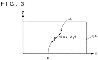
- the markers displayed on the respective display portions 34L and 34R are photographed by using a camera for measurement installed in a state in which an optical axis of the camera is made to align with each of central axes A of the ideal assembly positions of the display portion 34L and the lens 35L, and the display portion 34R and the lens 35R.
- a shift d( ⁇ x, ⁇ y) (represented by the coordinates of the display portion 34) between the images displayed on the corresponding display portions 34L and 34R visually recognized through the lenses 35L and 35R, and a point of view is measured.
- a row direction of the pixels is assigned an X-axis
- a direction orthogonally intersecting the X-axis is assigned a Y-axis.
- the control portion 21 of the information processing apparatus 11 is a program-controlled device such as a central processing unit (CPU) which operates in accordance with a program stored in the memory portion 22, or a graphics processing unit (GPU) as an image processing module.
- the control portion 21 of the present embodiment receives source image data becoming an object of display in the output apparatus 12, and produces corrected image data which is obtained by correcting a distortion of the lens 35 included in the output apparatus 12 through a predetermined conversion expression based on the source image data thus received.
- the control portion 21 outputs the resulting corrected image data to the output apparatus 12. An operation of the control portion 21 will be described later in detail.
- the memory portion 22 is a memory device, a disc device or the like.
- a program which is to be executed by the control portion 21 is stored in the memory portion 22.
- This program may be one which is stored in a computer readable and non-transitory recording medium such as a digital versatile disc read-only memory (DVD-ROM) in order to be presented, and may be stored in the memory portion 22.
- the memory portion 22 may operate as a work memory as well of the control portion 21, and a frame buffer area in which image data becoming an object of processing is stored, for example, may be set in the memory portion 22.
- the interface portion 23 for example, is a high-definition multimedia interface (HDMI) (registered trademark) port, a universal serial bus (USB) port or the like, and is connected to the output apparatus 12.
- HDMI high-definition multimedia interface
- USB universal serial bus
- the interface portion 23 outputs data (such as image data) to the output apparatus 12 in accordance with an instruction inputted thereto from the control portion 21.
- the interface portion 23 outputs information inputted thereto from the output apparatus 12 to the control portion 21.
- the control portion 31 of the output apparatus 12 is a program-controlled device, such as a CPU, which operates in accordance with the program stored in the memory portion 32.
- the control portion 31 executes processing for outputting corrected image data which is inputted from the information processing apparatus 11 through the I/O interface portion 33 to the display portion 34.
- the control portion 31 may execute processing for receiving a request for the information on the assembly error stored in the memory portion 32 from the outside (such as the information processing apparatus 11), reading out the information on the requested assembly error from the memory portion 32, and sending the information on the assembly error to the information processing apparatus 11 or the like as the requestor. An operation of the control portion 31 will be described later.
- the memory portion 32 is a memory device or the like, and a program which is to be executed by the control portion 31 is stored in the memory portion 32.
- This program may be one which is stored in a computer readable and non-transitory recording medium such as a DVD-ROM in order to be presented, and may be stored in the memory portion 32.
- the memory portion 32 may operate as a work memory as well of the control portion 31, and, for example, an area in which the corrected image data for display is to be stored may be set in the memory portion 32.
- the information on the assembly error which had been measured at the time of factory shipment is stored in the memory portion 32.
- the I/O interface portion 33 for example, is an HDMI (registered trademark) port, a USB port or the like, and is connected to the information processing apparatus 11 and the like.
- a pair of display portions 34L and 34R is a liquid crystal display or the like, and, as exemplified in FIG. 2 , is provided so as to correspond to each of the left and right eyes of the user (hereinafter, collectively written as the display portion 34 when it is unnecessary to make a distinction).
- Each of the display portions 34 includes a plurality of pixels 341.
- Each of the pixels 341 is further provided with sub-pixels 342 which emit light of R, light of G, and light of B.
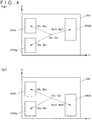
- the sub-pixels 342 are arranged in positions as exemplified in FIG. 4(a) or FIG. 4(b) every pixel 341.
- a center of a sub-pixel 342r of R is located in a position (Cx + Rx, Cy + Ry) which is (Rx, Ry) apart from a central coordinate (Cx, Cy) of the pixel 342 in both FIG. 4(a) and FIG. 4(b) .
- a center of a sub-pixel 342g of G is also located in a position (Cx + Gx, Cy + Gy) which is (Gx, Gy) apart from the central coordinate (Cx, Cy) of the pixel 342 in both FIG. 4(a) and FIG. 4(b) .
- a center of a sub-pixel 342b of B is located in a position (Cx + Bx1, Cy + By1) which is (Bx1, By1) apart from the central coordinate (Cx, Cy) of the pixel 342 in FIG. 4(a) .
- the central coordinate is determined as a point within either the pixel 341 or the sub-pixel 342 in advance like a point at which diagonals of a bounding rectangle of either the pixel 341 or the sub-pixel 342 cross each other.
- a pair of lenses 35L and 35R is arranged between the corresponding display portions 34L and 34R, and the eyes of the user who sees the images displayed on the display portions 34L and 34R concerned (that is, a display surface side of the display portion 34) (hereinafter, collectively written as the lens 35 when it is unnecessary to make a distinction).
- the lens 35 causes a predetermined distortion (for example, a pincushion distortion which contracts in a pincushion shape toward a central portion when a grid surface is displayed) to be generated in an image (an image corresponding to the corrected image data) displayed on the corresponding display portion 34, and causes the eye of the user to recognize the resulting image.
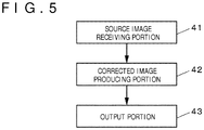
- the control portion 21 includes a source image receiving portion 41, a corrected image producing portion 42, and an output portion 42.
- the source image receiving portion 41 receives inputs of a pair of source image data for the left eye and the right eye.
- the control portion 21 executes processing as well (other pieces of processing), such as processing for a game, different from the correction of the image in parallel (in a time division manner).
- the source image receiving portion 41 may also receive the source image data from the other pieces of processing concerned.
- the corrected image producing portion 42 subjects each of a pair of source image data to conversion determined by a predetermined conversion expression (for example, an arithmetic expression of conversion for providing a barrel type distortion) for cancelling the distortion of the lens 35, and produces the corrected image data.
- a predetermined conversion expression for example, an arithmetic expression of conversion for providing a barrel type distortion
- the corrected image producing portion 42 successively selects the respective pixels constituting the corrected image data with respect to a pair of corrected image data for the left eye and the right eye, and obtains the pixel (the pixel coming out in the position of the pixel, on the corrected image data, selected by the conversion expression) on the source image data corresponding to the pixel on the corrected image data concerned through an arithmetic operation by the information on the position of the selected pixel, and the conversion expression described above. Then, the corrected image producing portion 42 determines the luminance of the selected pixel on the corrected image data, thereby producing the corrected image data based on the pixel value of the corresponding pixel on the source image.
- the corrected image producing portion 42 sends a request for the information on the assembly error to the output apparatus 12, and receives the information on the assembly error which the output apparatus 12 outputs in response to the request concerned to store the information on the assembly error in the memory portion 22.
- a timing at which the information on the assembly error is obtained may be set at any time as long as the timing is set until before next processing is executed.
- the corrected image producing portion 42 reads out the information on the assembly error about the lens 35L and the display portion 34L on the left eye side from the memory portion 22, and moves in parallel the corrected image data on the left eye by an amount corresponding to the information on the error thus read out. That is to say, the corrected image producing portion 42 moves in parallel the whole of the corrected image data for the left eye in such a way that the pixel to be displayed at the center of the display portion 34L of the corrected image data becomes in position the pixel of the display portion 34L on the optical axis of the line of sight of the user visually recognized through the lens 35L. Thus, the corrected image producing portion 42 obtains second corrected image data for the left eye.
- the corrected image producing portion 42 reads out the information on the assembly error about the lens 35R and the display portion 34R on the right eye side from the memory portion 22, and moves in parallel the corrected image data on the left eye by an amount corresponding to the information on the error thus read out.
- the corrected image producing portion 42 moves in parallel the whole of the corrected image data for the right eye in such a way that the pixel to be displayed at the center of the display portion 34R of the corrected image data becomes in position the pixel of the display portion 34R on the optical axis of the line of sight of the user visually recognized through the lens 35R.
- the corrected image producing portion 42 obtains second corrected image data for the right eye.
- the output portion 43 outputs second corrected image data produced in the corrected image processing portion 42.
- the information processing system of the present embodiment includes the configuration described above, and operates as follows.
- the control portion 21 of the information processing apparatus 11 sends the request for the information on the assembly error to the output apparatus 12, and receives the information on the assembly error which the output apparatus 12 outputs in response to the request concerned to store the information on the assembly error in the memory portion 22.
- control portion 21 secures an area in which the corrected image data corresponding to a pair of source image data, for the left eye and the right eye, produced in the processing for a game is to be stored in the memory portion 22.
- the control portion 21 executes the following processing with respect to each of a pair of corrected image data. That is to say, the control portion 21 successively selects the pixels contained in the corrected image data. The control portion 21 calculates the central coordinate of the selected pixel.
- the control portion 21 obtains the coordinate on the source image data which is converted into the central coordinate of the pixel concerned by the conversion expression serving to cancel a distortion of the lens 35 as the corresponding coordinate through the arithmetic operation. Then, the control portion 21 determines the luminance of the selected sub-pixel based on the pixel value (a component of the pixel value corresponding to the color of the selected sub-pixel) in the pixel (there may be a plurality of pixels) falling within a predetermined range with the corresponding coordinates as a center on the source image data. The control portion 21 executes this processing every pixel, thereby obtaining the pixel values of the respective pixels contained in the corrected image data. In addition, the control portion 21 individually executes these pieces of processing with respect to the left eye and the right eye, thereby producing a pair of corrected image data for the left eye and the right eye.
- control portion 21 reads out the information on the assembly error with respect to the lens 35L and the display portion 34L on the left eye side from the memory portion 22, and moves in parallel the corrected image data for the left eye by the amount corresponding to the information on the error thus read out to obtain the second corrected image data for the left eye.
- control portion 21 reads out the information on the assembly error with respect to the lens 35R and the display portion 34R on the right eye side from the memory portion 22, and moves in parallel the corrected image data for the right eye by the amount corresponding to the information on the error thus read out to obtain the second corrected image data for the right eye.
- control portion 21 outputs a pair of second corrected image data thus produced to the output apparatus 12 through the interface portion 23.
- the second corrected image data for the left eye thus inputted is displayed on the display portion 34L for the left eye
- the second corrected image data for the right eye thus inputted is displayed on the display portion 34R for the right eye.
- the image (the image represented by the corrected image data) displayed on the display portion 34 of the output apparatus 12 differs in position in units of a pixel every output apparatus 12 in some cases (becomes the same between the output apparatus 12 with which the errors at the time of the assembly agree with each other every corner).
- the corrected image producing portion 42 may execute the processing in which it is taken into consideration that the central position of the sub-pixel and the central position of the pixel are shifted from each other.
- the processing for producing the corrected image data by the corrected image producing portion 42 is as follows. That is to say, the corrected image producing portion 42 executes next processing for producing the corrected image data with respect to each of a pair of source image data.
- the corrected image producing portion 42 executes next processing for producing the corrected image data with respect to any of the source image data, as exemplified in FIG. 6 .
- the corrected image producing portion 42 secures an area in which the corrected image data is to be stored in the memory portion 22 (S1). This area is secured in correspondence to the number of pixels in the display portion 34 of the output apparatus 12.
- the corrected image producing portion 42 selects one of the pixels 341 of the corrected image data (S2). It is only necessary that this selection, for example, is carried out in the order of scanning line from the pixel in a top-left corner. In other words, it is only necessary that the pixels are successively selected from the left to the right in a row of the pixels located in the uppermost side, and next, the selection is shifted for next row therebelow (one row therebelow), and the pixels are successively selected from the left to the right again, and so forth.
- the selection of the pixels is by no means limited to this order, and the pixels may be selected in the arbitrary order.
- a plurality of pixels is selected in parallel to execute next processing.
- the corrected image producing portion 42 selects one of the pixels 341 corresponding to the corrected image data, the corrected image producing portion 42 successively selects the sub-pixels 342 included in the pixel thus selected (S3). Specifically, it is only necessary to select the sub-pixels in a predetermined order such as an order of R, G, and B.
- the corrected image producing portion 42 calculates the position of the central coordinate of the sub-pixel 342 selected in the processing S3 by using the central coordinate (Cx, Cy) of the pixel 341 selected in the processing S2 (S4).
- the central coordinate of the sub-pixel 342 can be calculated by referring to information which represents how much far the central coordinate of each of the sub-pixels 342 is located apart from the central coordinate of the pixel 341 and is stored in the memory portion 22 in advance.
- the central coordinate of at least one sub-pixel 342 is different depending on the pixels 341 (for example, as exemplified in FIGS. 4(a) and 4(b) , when there are two kinds of arrangements, and so forth)
- the information representing how much far the central coordinate of each of the sub-pixels 342 is located apart from the central coordinate of the pixel 341 is stored in the memory portion 22.
- information specifying the pixel 341 and information representing which kind of arrangement the sub-pixel 342 takes in the pixel 341 specified by that information are stored in the memory portion 22 with being assembled with each other every pixel 341.
- the corrected image producing portion 42 specifies the kind of arrangement in the pixel 341 selected in the processing S2 based on the information concerned.
- the corrected image producing portion 42 calculates the positions of the central coordinates of the respective sub-pixels 342 by referring to the information (the information on the position of the sub-pixel 342 representing how much far the central coordinate of the sub-pixel 342 is located apart from the central coordinate of the pixel 341) on the central coordinates of the respective sub-pixels 342 in the arrangement having the kind thus specified.
- the central coordinate of at least one sub-pixel 342 is different depending on the pixel 341 (for example, as exemplified in FIGS. 4(a) and 4(b) , when there are the two kinds of arrangements, and so forth), the information representing how much far the central coordinate of each of the sub-pixels 342 is located apart from the central coordinate of the pixel 341 with respect to each of the pixels 341 may be averaged to obtain the average central coordinate of the respective sub-pixels 342.
- the resulting average central coordinate of the sub-pixel 342 may be stored in the memory portion 22 in advance.
- the corrected image producing portion 42 reads out the information (average information) representing how much far it is located apart from the central coordinate of the pixel 341 selected in the processing S2 from the memory portion 22 and refers to that information, thereby calculating the positions of the central coordinates of the respective sub-pixels 342.
- the corrected image producing portion 42 obtains the corresponding coordinate on the source image data, corresponding to the central coordinate of the sub-pixel 342 through the arithmetic operation, calculated in the processing S4 (S5). With that arithmetic operation, the coordinate on the source image data which is converted into the central coordinate of the sub-pixel 342 selected by a predetermined conversion expression is obtained as the corresponding coordinate through the arithmetic operation by using the predetermined conversion expression, cancelling the distortion of lens 35, for obtaining the corrected image data from the source image data, and the central coordinate of the sub-pixel 342 calculated in the processing S4. Since the concrete calculating method is generally known, a detailed description thereof is omitted herein.
- the corrected image producing portion 42 determines the luminance of the sub-pixel 342 selected in the processing S3 based on the pixel values (the component of the pixel value corresponding to the color of the sub-pixel 342 selected in the processing S3) in the pixel (there may be a plurality of pixels) falling within the predetermined range on the source image data with the corresponding coordinate on the source image data obtained as the center (S6).
- the luminance of the sub-pixel 342 selected in the processing S3 is determined based on the red color component (the value of R of RGB values) of the pixel value of the pixel falling within a predetermined range on the source image data with the corresponding coordinate on the source image as the center.
- the value of the corresponding coordinate obtained from the processing S5 is not located at the center of any of the pixels. Therefore, the determination of the luminance herein is obtained by interpolating the pixel values in the pixels falling within the predetermined range with the resulting corresponding coordinate on the source image data as the center.
- the interpolations which are generally known, such as nearest neighbor interpolation, bilinear interpolation, and bicubic interpolation can be used as this interpolation method.
- the arithmetic operation relating to the processing S5 and S6 can be carried out by utilizing lens distortion correcting processing using software such as an Open CV.
- the corrected image producing portion 42 repeatedly executes the processing from S3 to S6 with respect to the respective sub-pixels 342.
- the luminances of the sub-pixels 342 included in the pixel 341 selected in the processing S2 are individually determined, and the pixel value of the pixel 341 concerned is determined. That is to say, in the example of the present embodiment, one of the features is such that the corresponding pixel within the source image data is specified based on the position within the pixel not every pixel, but every sub-pixel, and the luminance of the sub-pixel is determined by using the color component of the sub-pixel of the pixel value of the specified pixel concerned, thereby obtaining the corrected image data.
- the corrected image producing portion 42 repeatedly executes the processing from the processing S2 to the processing S6 with respect to the respective pixels 341. As a result, the corrected image producing portion 42 successively obtains the pixel values, of the respective pixels 341, contained in the corrected image data. In addition, the corrected image producing portion 42 executes the processing described above with respect to the left eye and the right eye, thereby producing a pair of corrected image data for the left eye and the right eye.
- the arrangement of the sub-pixels for example, is one depicted in FIG. 4(a) or FIG. 4(b)
- the arrangement of the sub-pixels is asymmetric with respect to the horizontal line. Therefore, when a pair of images which is symmetric with respect to the horizontal line is made the source image data, the resulting pieces of corrected image data obtained therefrom become the results different from each other.
- the correction processing for the assembly error of the display and the lens, and the correction processing coping with the position shift between the pixel center and the sub-pixel center are individually executed, these pieces of correction processing may be executed as one correction processing once.
- the information on the positions of the sub-pixels within the respective pixels in the display portion 34 of the output apparatus 12 is stored in the memory portion 22.
- the information on the positions of the sub-pixels may also be stored at the time of installation of the driver of the output apparatus 12.
- the information processing apparatus 11 may acquire the information on the positions of the sub-pixels from the output apparatus 12, and may store the information on the positions of the sub-pixels in the memory portion 22.
- the information (either the information representing how much far the central coordinates of the respective sub-pixels 342 are located apart from the central coordinates of the respective pixels 341, or the information representing how much far the central coordinates of the respective sub-pixels 342 are located in average apart from the central coordinates of the pixels 341) representing the positions of the sub-pixels within the pixels in the display portion 34 is stored in the memory portion 32 of the output apparatus 12. That information, for example, is written to the memory portion 32 at the time of the factory shipment or the like.
- control portion 31 of the output apparatus 12 receives the request for the information on the positions of the sub-pixels from the outside (such as the information processing apparatus 11), the control portion 31 outputs the information on the positions of the sub-pixels stored in the memory portion 32 to the information processing apparatus 11 as the request source in response to the request concerned.
- the information processing apparatus 11 acquires the information on the positions of the sub-pixels from the output apparatus 12 in the stage, before the processing for producing the corrected image data is executed, at the timing at which the output apparatus 12 is connected, or the like, and stores the information on the positions of the sub-pixels in the memory portion 22.
- the information processing apparatus 11 uses the information on the positions of the sub-pixels in the processing for producing the corrected image data.
- the processing for producing the corrected image data may be executed on the assumption that the central coordinates of all the sub-pixels are located at the centers of the respective pixels of the source image data.
- the processing for image deformation which has been general in the past can be used, a detailed description is omitted herein.
- the output apparatus 12 sends the information, on the assembly error of the lens 35, which had been written at the time of the factory shipment to the information processing apparatus 11 in response to the request.
- the present embodiment is by no means limited thereto.
- the output apparatus 12 may be provided with a device for measuring the position shift between the optical axis of the lens 35 and the center of the corresponding display portion 34.
- a device for measuring the position shift between the optical axis of the lens 35 and the center of the corresponding display portion 34 Specifically, an auto-collimator which is generally known may be used as this device.
- the measurement of the assembly error may be one for measuring the position shift with respect to an ideal optical axis, or may be one for measuring the relative position shift between the optical axis of the lens and the center of the display portion 34.
- the control portion 31 of the output apparatus 12 instead of reading out the information on the assembly error stored in the memory portion 32 in response to the request for the information on the assembly error from the outside (such as the information processing apparatus 11), the control portion 31 of the output apparatus 12 measures the position shift between the optical axes of the lenses 35L and 35R, and the centers of the corresponding display portions 34L and 34R, and outputs the information on the assembly error thus measured to the information processing apparatus 11 or the like as the request source.
Landscapes
- Engineering & Computer Science (AREA)
- Physics & Mathematics (AREA)
- General Physics & Mathematics (AREA)
- Theoretical Computer Science (AREA)
- Multimedia (AREA)
- Signal Processing (AREA)
- Optics & Photonics (AREA)
- Human Computer Interaction (AREA)
- General Engineering & Computer Science (AREA)
- Computer Hardware Design (AREA)
- Image Processing (AREA)
- Transforming Electric Information Into Light Information (AREA)
- Controls And Circuits For Display Device (AREA)
- Geometry (AREA)
Abstract
Description
- The present invention relates to an information processing system, an information processing apparatus, an output apparatus, a program, and a recording medium.
- In recent years, for example, like a head-mounted display or a smart glass, there has been an output apparatus which a user mounts on his/her head to use. Such an output apparatus is provided with a pair of displays which are individually disposed in front of the left and right eyes of the user, and presents images displayed on the displays to the user. Since such an output apparatus enables the user to visually recognize a picture having realistic sensation, the output apparatus is utilized in a virtual reality technique and the like.
- With such an output apparatus, in order to widen a viewing angle thereof, images displayed on the displays can be dared to be formed in front of the eyes of the user through lenses each having a strong distortion. When such lenses are used, the images displayed on the displays are not the images themselves presented to the user. That is to say, corrected images for which a distortion reverse to a lens distortion is previously given to the original images (source images) are produced, and the corrected images are displayed. As a result, the images which are visually recognized by the user through the lenses become ones corresponding to the source images.
- However, if there was an error in mounting position when this lens was mounted at the time of manufacture, and an optical axis of the lens and the center of the display was shifted, then, the centers of the respective images which were seen by the left and right eyes of the user were shifted. Thus, there was the case where the directions of the lines of sight of the left and the right did not cross each other (becoming outward), or there was the case where the lines of sight became inward. For this reason, heretofore, there was a problem that the intended sense of distance could not be presented to the user.
- The present invention has been made in the light of the actual situation described above, and one of objects thereof is to provide an information processing system, an information processing apparatus, an output apparatus, a program, and a recording medium each of which is capable of presenting an intended sense of distance to a user.
- The present invention made in order to solve the problems in the past example is an information processing system having an output apparatus and an information processing apparatus. The output apparatus includes a display portion including a plurality of sub-pixels every pixel, a lens disposed on a display surface side of the display portion, and means for outputting information, on an assembly error, representing position shift between an optical axis of the lens and a center of the display portion. The information processing apparatus acquires the information on the assembly error from the output apparatus and includes corrected image data producing means, and mean for outputting second corrected image data produced by the corrected image data producing means. The corrected image data producing means produces second corrected image data which is obtained by further moving in parallel corrected image data produced by carrying out predetermined correction based on source image data becoming an object of display, based on the information on the assembly error acquired. The output apparatus displays the second corrected image data output by the information processing apparatus on the display portion.
- According to the present invention, an intended sense of distance can be presented to a user.
-
- [
FIG. 1 ]
FIG. 1 is a configuration block diagram representing an example of an information processing system according to an embodiment of the present invention. - [
FIG. 2 ]
FIG. 2 is a configuration block diagram representing an example of an output apparatus according to the embodiment of the present invention. - [
FIG. 3 ]
FIG. 3 is an explanatory diagram representing an example of a method of measuring an assembly error of a lens in the output apparatus according to the embodiment of the present invention. - [
FIG. 4 ]
FIG. 4 depicts explanatory diagrams representing an example of arrangement positions of sub-pixels of a display portion of the output apparatus according to the embodiment of the present invention. - [
FIG. 5 ]
FIG. 5 is a functional block diagram representing an example of an information processing apparatus according to the embodiment of the present invention. - [
FIG. 6 ]
FIG. 6 is a flow chart representing a processing example of the information processing apparatus according to the embodiment of the present invention. - An embodiment of the present invention will be described with reference to the drawings. An information processing system 10 according to the embodiment of the present invention, as exemplified in
FIG. 1 , includes aninformation processing apparatus 11 and anoutput apparatus 12. - In an example of the present embodiment, the
information processing apparatus 11, for example, is computer-based equipment such as a home-use video game system. Specifically, as depicted inFIG. 1 , theinformation processing apparatus 11 includes acontrol portion 21, amemory portion 22, and aninterface portion 23. In addition, theoutput apparatus 12, for example, is a head-mounted display. As schematically exemplified inFIG. 2 , theoutput apparatus 12 includes acontrol portion 31, amemory portion 32, an input/output (I/O)interface portion 33, a pair ofdisplay portions lenses - In addition, in the present embodiment, for the
output apparatus 12, at the time of factory shipment, an assembly error of a pair ofdisplay portions display portion 34 when it is unnecessary to make a distinction), and the lens 35 (thelens 35L on the left eye side, and thelens 35R on the right eye side) is measured. This measurement can be carried out by using the generally known method. Specifically, this measurement is carried out as follows. Firstly, after thedisplay portions display portions respective display portions - Next, the markers displayed on the
respective display portions display portion 34L and thelens 35L, and thedisplay portion 34R and thelens 35R. - Then, how much far the cross point c represented by the images of the markers thus photographed is shifted from the position corresponding to the optical axis of the camera for measurement is measured.
- As a result, a shift d(Δx, Δy) (represented by the coordinates of the display portion 34) between the images displayed on the
corresponding display portions lenses lens 35L and thedisplay portion 34L on the left eye side, and the set oflens 35R and thedisplay portion 34R on the right eye side) are stored as information on the assembly error in thememory portion 32. - The
control portion 21 of theinformation processing apparatus 11 is a program-controlled device such as a central processing unit (CPU) which operates in accordance with a program stored in thememory portion 22, or a graphics processing unit (GPU) as an image processing module. Thecontrol portion 21 of the present embodiment receives source image data becoming an object of display in theoutput apparatus 12, and produces corrected image data which is obtained by correcting a distortion of the lens 35 included in theoutput apparatus 12 through a predetermined conversion expression based on the source image data thus received. In addition, thecontrol portion 21 outputs the resulting corrected image data to theoutput apparatus 12. An operation of thecontrol portion 21 will be described later in detail. - The
memory portion 22 is a memory device, a disc device or the like. A program which is to be executed by thecontrol portion 21 is stored in thememory portion 22. This program may be one which is stored in a computer readable and non-transitory recording medium such as a digital versatile disc read-only memory (DVD-ROM) in order to be presented, and may be stored in thememory portion 22. In addition, thememory portion 22 may operate as a work memory as well of thecontrol portion 21, and a frame buffer area in which image data becoming an object of processing is stored, for example, may be set in thememory portion 22. - The
interface portion 23, for example, is a high-definition multimedia interface (HDMI) (registered trademark) port, a universal serial bus (USB) port or the like, and is connected to theoutput apparatus 12. In addition, theinterface portion 23 outputs data (such as image data) to theoutput apparatus 12 in accordance with an instruction inputted thereto from thecontrol portion 21. In addition, theinterface portion 23 outputs information inputted thereto from theoutput apparatus 12 to thecontrol portion 21. - The
control portion 31 of theoutput apparatus 12 is a program-controlled device, such as a CPU, which operates in accordance with the program stored in thememory portion 32. In the present embodiment, thecontrol portion 31 executes processing for outputting corrected image data which is inputted from theinformation processing apparatus 11 through the I/O interface portion 33 to thedisplay portion 34. In addition, thecontrol portion 31 may execute processing for receiving a request for the information on the assembly error stored in thememory portion 32 from the outside (such as the information processing apparatus 11), reading out the information on the requested assembly error from thememory portion 32, and sending the information on the assembly error to theinformation processing apparatus 11 or the like as the requestor. An operation of thecontrol portion 31 will be described later. - The
memory portion 32 is a memory device or the like, and a program which is to be executed by thecontrol portion 31 is stored in thememory portion 32. This program may be one which is stored in a computer readable and non-transitory recording medium such as a DVD-ROM in order to be presented, and may be stored in thememory portion 32. In addition, thememory portion 32 may operate as a work memory as well of thecontrol portion 31, and, for example, an area in which the corrected image data for display is to be stored may be set in thememory portion 32. Moreover, as previously stated in the present embodiment, the information on the assembly error which had been measured at the time of factory shipment is stored in thememory portion 32. - The I/
O interface portion 33, for example, is an HDMI (registered trademark) port, a USB port or the like, and is connected to theinformation processing apparatus 11 and the like. - A pair of
display portions FIG. 2 , is provided so as to correspond to each of the left and right eyes of the user (hereinafter, collectively written as thedisplay portion 34 when it is unnecessary to make a distinction). Each of thedisplay portions 34 includes a plurality ofpixels 341. Each of thepixels 341 is further provided with sub-pixels 342 which emit light of R, light of G, and light of B. The sub-pixels 342 are arranged in positions as exemplified inFIG. 4(a) or FIG. 4(b) everypixel 341. In this example, a center of a sub-pixel 342r of R is located in a position (Cx + Rx, Cy + Ry) which is (Rx, Ry) apart from a central coordinate (Cx, Cy) of the pixel 342 in bothFIG. 4(a) and FIG. 4(b) . In addition, a center of a sub-pixel 342g of G is also located in a position (Cx + Gx, Cy + Gy) which is (Gx, Gy) apart from the central coordinate (Cx, Cy) of the pixel 342 in bothFIG. 4(a) and FIG. 4(b) . On the other hand, a center of a sub-pixel 342b of B is located in a position (Cx + Bx1, Cy + By1) which is (Bx1, By1) apart from the central coordinate (Cx, Cy) of the pixel 342 inFIG. 4(a) . InFIG. 4(b) , the center of the sub-pixel 342b of B is located in a position (Cx + Bx2, Cy + By2) which is (Bx2, By2) (Bx1 = Bx2 and By1 ≠ By2 in the examples ofFIGS. 4(a) and 4(b) ) apart from the central coordinate (Cx, Cy) of the pixel 342. It should be noted that here, the central coordinate is determined as a point within either thepixel 341 or the sub-pixel 342 in advance like a point at which diagonals of a bounding rectangle of either thepixel 341 or the sub-pixel 342 cross each other. - A pair of
lenses corresponding display portions display portions corresponding display portion 34, and causes the eye of the user to recognize the resulting image. - Here, a description will be given with respect to an operation of the
control portion 21 of theinformation processing apparatus 11. Thecontrol portion 21, as exemplified functionally inFIG. 5 , includes a sourceimage receiving portion 41, a correctedimage producing portion 42, and anoutput portion 42. Here, the sourceimage receiving portion 41 receives inputs of a pair of source image data for the left eye and the right eye. In an example of the present embodiment, thecontrol portion 21 executes processing as well (other pieces of processing), such as processing for a game, different from the correction of the image in parallel (in a time division manner). Thus, the sourceimage receiving portion 41 may also receive the source image data from the other pieces of processing concerned. - The corrected
image producing portion 42 subjects each of a pair of source image data to conversion determined by a predetermined conversion expression (for example, an arithmetic expression of conversion for providing a barrel type distortion) for cancelling the distortion of the lens 35, and produces the corrected image data. - Specifically, the corrected
image producing portion 42 successively selects the respective pixels constituting the corrected image data with respect to a pair of corrected image data for the left eye and the right eye, and obtains the pixel (the pixel coming out in the position of the pixel, on the corrected image data, selected by the conversion expression) on the source image data corresponding to the pixel on the corrected image data concerned through an arithmetic operation by the information on the position of the selected pixel, and the conversion expression described above. Then, the correctedimage producing portion 42 determines the luminance of the selected pixel on the corrected image data, thereby producing the corrected image data based on the pixel value of the corresponding pixel on the source image. - In addition, the corrected
image producing portion 42 sends a request for the information on the assembly error to theoutput apparatus 12, and receives the information on the assembly error which theoutput apparatus 12 outputs in response to the request concerned to store the information on the assembly error in thememory portion 22. A timing at which the information on the assembly error is obtained may be set at any time as long as the timing is set until before next processing is executed. - The corrected
image producing portion 42 reads out the information on the assembly error about thelens 35L and thedisplay portion 34L on the left eye side from thememory portion 22, and moves in parallel the corrected image data on the left eye by an amount corresponding to the information on the error thus read out. That is to say, the correctedimage producing portion 42 moves in parallel the whole of the corrected image data for the left eye in such a way that the pixel to be displayed at the center of thedisplay portion 34L of the corrected image data becomes in position the pixel of thedisplay portion 34L on the optical axis of the line of sight of the user visually recognized through thelens 35L. Thus, the correctedimage producing portion 42 obtains second corrected image data for the left eye. In addition, the correctedimage producing portion 42 reads out the information on the assembly error about thelens 35R and thedisplay portion 34R on the right eye side from thememory portion 22, and moves in parallel the corrected image data on the left eye by an amount corresponding to the information on the error thus read out. In other words, the correctedimage producing portion 42 moves in parallel the whole of the corrected image data for the right eye in such a way that the pixel to be displayed at the center of thedisplay portion 34R of the corrected image data becomes in position the pixel of thedisplay portion 34R on the optical axis of the line of sight of the user visually recognized through thelens 35R. Thus, the correctedimage producing portion 42 obtains second corrected image data for the right eye. - The
output portion 43 outputs second corrected image data produced in the correctedimage processing portion 42. - The information processing system of the present embodiment includes the configuration described above, and operates as follows.
- The
control portion 21 of theinformation processing apparatus 11 sends the request for the information on the assembly error to theoutput apparatus 12, and receives the information on the assembly error which theoutput apparatus 12 outputs in response to the request concerned to store the information on the assembly error in thememory portion 22. - Then, the
control portion 21 secures an area in which the corrected image data corresponding to a pair of source image data, for the left eye and the right eye, produced in the processing for a game is to be stored in thememory portion 22. - The
control portion 21 executes the following processing with respect to each of a pair of corrected image data. That is to say, thecontrol portion 21 successively selects the pixels contained in the corrected image data. Thecontrol portion 21 calculates the central coordinate of the selected pixel. - The
control portion 21 obtains the coordinate on the source image data which is converted into the central coordinate of the pixel concerned by the conversion expression serving to cancel a distortion of the lens 35 as the corresponding coordinate through the arithmetic operation. Then, thecontrol portion 21 determines the luminance of the selected sub-pixel based on the pixel value (a component of the pixel value corresponding to the color of the selected sub-pixel) in the pixel (there may be a plurality of pixels) falling within a predetermined range with the corresponding coordinates as a center on the source image data. Thecontrol portion 21 executes this processing every pixel, thereby obtaining the pixel values of the respective pixels contained in the corrected image data. In addition, thecontrol portion 21 individually executes these pieces of processing with respect to the left eye and the right eye, thereby producing a pair of corrected image data for the left eye and the right eye. - Further, the
control portion 21 reads out the information on the assembly error with respect to thelens 35L and thedisplay portion 34L on the left eye side from thememory portion 22, and moves in parallel the corrected image data for the left eye by the amount corresponding to the information on the error thus read out to obtain the second corrected image data for the left eye. In addition, thecontrol portion 21 reads out the information on the assembly error with respect to thelens 35R and thedisplay portion 34R on the right eye side from thememory portion 22, and moves in parallel the corrected image data for the right eye by the amount corresponding to the information on the error thus read out to obtain the second corrected image data for the right eye. - Then, the
control portion 21 outputs a pair of second corrected image data thus produced to theoutput apparatus 12 through theinterface portion 23. In theoutput apparatus 12, the second corrected image data for the left eye thus inputted is displayed on thedisplay portion 34L for the left eye, and the second corrected image data for the right eye thus inputted is displayed on thedisplay portion 34R for the right eye. - These pieces of second corrected image data thus displayed are obtained through such correction as to cancel the distortion of the lens 35 as described above. These pieces of second corrected image data thus displayed suffer the distortion of the lens 35 through the corresponding
lenses display 34 and the lens 35 are arranged off the desired positions at the time of the assembly, the image which is displayed on thedisplay 34 is corrected in such a way that the center of the original source image data is located on the optical axis of the line of sight of the user through the lens 35. Therefore, it is possible to provide the intended sense of perspective for the user. - In the example of the present embodiment, the image (the image represented by the corrected image data) displayed on the
display portion 34 of theoutput apparatus 12 differs in position in units of a pixel everyoutput apparatus 12 in some cases (becomes the same between theoutput apparatus 12 with which the errors at the time of the assembly agree with each other every corner). - Processing in which it is taken into consideration that central position of sub-pixel and central position of pixel are shifted Moreover, in a certain example of the present embodiment, in carrying out the correction for cancelling the distortion of the lens 35, the corrected
image producing portion 42 may execute the processing in which it is taken into consideration that the central position of the sub-pixel and the central position of the pixel are shifted from each other. - In this case, the processing for producing the corrected image data by the corrected
image producing portion 42 is as follows. That is to say, the correctedimage producing portion 42 executes next processing for producing the corrected image data with respect to each of a pair of source image data. When the correctedimage producing portion 42 starts the processing for producing the corrected image data with respect to any of the source image data, as exemplified inFIG. 6 , the correctedimage producing portion 42 secures an area in which the corrected image data is to be stored in the memory portion 22 (S1). This area is secured in correspondence to the number of pixels in thedisplay portion 34 of theoutput apparatus 12. - The corrected
image producing portion 42 selects one of thepixels 341 of the corrected image data (S2). It is only necessary that this selection, for example, is carried out in the order of scanning line from the pixel in a top-left corner. In other words, it is only necessary that the pixels are successively selected from the left to the right in a row of the pixels located in the uppermost side, and next, the selection is shifted for next row therebelow (one row therebelow), and the pixels are successively selected from the left to the right again, and so forth. Of course, the selection of the pixels is by no means limited to this order, and the pixels may be selected in the arbitrary order. In addition, by utilizing a GPU, a plurality of pixels is selected in parallel to execute next processing. - When the corrected
image producing portion 42 selects one of thepixels 341 corresponding to the corrected image data, the correctedimage producing portion 42 successively selects the sub-pixels 342 included in the pixel thus selected (S3). Specifically, it is only necessary to select the sub-pixels in a predetermined order such as an order of R, G, and B. The correctedimage producing portion 42 calculates the position of the central coordinate of the sub-pixel 342 selected in the processing S3 by using the central coordinate (Cx, Cy) of thepixel 341 selected in the processing S2 (S4). - If the arrangements of the sub-pixels 342 are identical to one another in all the
pixels 341, the central coordinate of the sub-pixel 342 can be calculated by referring to information which represents how much far the central coordinate of each of the sub-pixels 342 is located apart from the central coordinate of thepixel 341 and is stored in thememory portion 22 in advance. - In addition, when the central coordinate of at least one sub-pixel 342 is different depending on the pixels 341 (for example, as exemplified in
FIGS. 4(a) and 4(b) , when there are two kinds of arrangements, and so forth), the information representing how much far the central coordinate of each of the sub-pixels 342 is located apart from the central coordinate of thepixel 341 is stored in thememory portion 22. In addition, information specifying thepixel 341 and information representing which kind of arrangement the sub-pixel 342 takes in thepixel 341 specified by that information are stored in thememory portion 22 with being assembled with each other everypixel 341. The correctedimage producing portion 42 specifies the kind of arrangement in thepixel 341 selected in the processing S2 based on the information concerned. In addition, the correctedimage producing portion 42 calculates the positions of the central coordinates of the respective sub-pixels 342 by referring to the information (the information on the position of the sub-pixel 342 representing how much far the central coordinate of the sub-pixel 342 is located apart from the central coordinate of the pixel 341) on the central coordinates of the respective sub-pixels 342 in the arrangement having the kind thus specified. - Moreover, when the central coordinate of at least one sub-pixel 342 is different depending on the pixel 341 (for example, as exemplified in
FIGS. 4(a) and 4(b) , when there are the two kinds of arrangements, and so forth), the information representing how much far the central coordinate of each of the sub-pixels 342 is located apart from the central coordinate of thepixel 341 with respect to each of thepixels 341 may be averaged to obtain the average central coordinate of the respective sub-pixels 342. The resulting average central coordinate of the sub-pixel 342 may be stored in thememory portion 22 in advance. In this case, the correctedimage producing portion 42 reads out the information (average information) representing how much far it is located apart from the central coordinate of thepixel 341 selected in the processing S2 from thememory portion 22 and refers to that information, thereby calculating the positions of the central coordinates of the respective sub-pixels 342. - The corrected
image producing portion 42 obtains the corresponding coordinate on the source image data, corresponding to the central coordinate of the sub-pixel 342 through the arithmetic operation, calculated in the processing S4 (S5). With that arithmetic operation, the coordinate on the source image data which is converted into the central coordinate of the sub-pixel 342 selected by a predetermined conversion expression is obtained as the corresponding coordinate through the arithmetic operation by using the predetermined conversion expression, cancelling the distortion of lens 35, for obtaining the corrected image data from the source image data, and the central coordinate of the sub-pixel 342 calculated in the processing S4. Since the concrete calculating method is generally known, a detailed description thereof is omitted herein. - The corrected
image producing portion 42 determines the luminance of the sub-pixel 342 selected in the processing S3 based on the pixel values (the component of the pixel value corresponding to the color of the sub-pixel 342 selected in the processing S3) in the pixel (there may be a plurality of pixels) falling within the predetermined range on the source image data with the corresponding coordinate on the source image data obtained as the center (S6). For example, when the color of the sub-pixel 342 selected in the processing S3 is R (red), in this case, the luminance of the sub-pixel 342 selected in the processing S3 is determined based on the red color component (the value of R of RGB values) of the pixel value of the pixel falling within a predetermined range on the source image data with the corresponding coordinate on the source image as the center. - In general, the value of the corresponding coordinate obtained from the processing S5 is not located at the center of any of the pixels. Therefore, the determination of the luminance herein is obtained by interpolating the pixel values in the pixels falling within the predetermined range with the resulting corresponding coordinate on the source image data as the center. The interpolations, which are generally known, such as nearest neighbor interpolation, bilinear interpolation, and bicubic interpolation can be used as this interpolation method. As an example, the arithmetic operation relating to the processing S5 and S6 can be carried out by utilizing lens distortion correcting processing using software such as an Open CV.
- The corrected
image producing portion 42 repeatedly executes the processing from S3 to S6 with respect to the respective sub-pixels 342. As a result, the luminances of the sub-pixels 342 included in thepixel 341 selected in the processing S2 are individually determined, and the pixel value of thepixel 341 concerned is determined. That is to say, in the example of the present embodiment, one of the features is such that the corresponding pixel within the source image data is specified based on the position within the pixel not every pixel, but every sub-pixel, and the luminance of the sub-pixel is determined by using the color component of the sub-pixel of the pixel value of the specified pixel concerned, thereby obtaining the corrected image data. - The corrected
image producing portion 42 repeatedly executes the processing from the processing S2 to the processing S6 with respect to therespective pixels 341. As a result, the correctedimage producing portion 42 successively obtains the pixel values, of therespective pixels 341, contained in the corrected image data. In addition, the correctedimage producing portion 42 executes the processing described above with respect to the left eye and the right eye, thereby producing a pair of corrected image data for the left eye and the right eye. - In the corrected image data produced by the
information processing apparatus 11 according to the example of the present embodiment, when the arrangement of the sub-pixels, for example, is one depicted inFIG. 4(a) or FIG. 4(b) , since the sub-pixels of R and G are arranged in the longitudinal direction, the arrangement of the sub-pixels is asymmetric with respect to the horizontal line. Therefore, when a pair of images which is symmetric with respect to the horizontal line is made the source image data, the resulting pieces of corrected image data obtained therefrom become the results different from each other. In addition, in this case, although the correction processing for the assembly error of the display and the lens, and the correction processing coping with the position shift between the pixel center and the sub-pixel center are individually executed, these pieces of correction processing may be executed as one correction processing once. - In the present embodiment, the information on the positions of the sub-pixels within the respective pixels in the
display portion 34 of theoutput apparatus 12 is stored in thememory portion 22. However, the information on the positions of the sub-pixels, for example, may also be stored at the time of installation of the driver of theoutput apparatus 12. - In another example of the present embodiment, when the
output apparatus 12 is connected, theinformation processing apparatus 11 may acquire the information on the positions of the sub-pixels from theoutput apparatus 12, and may store the information on the positions of the sub-pixels in thememory portion 22. In this example, the information (either the information representing how much far the central coordinates of the respective sub-pixels 342 are located apart from the central coordinates of therespective pixels 341, or the information representing how much far the central coordinates of the respective sub-pixels 342 are located in average apart from the central coordinates of the pixels 341) representing the positions of the sub-pixels within the pixels in thedisplay portion 34 is stored in thememory portion 32 of theoutput apparatus 12. That information, for example, is written to thememory portion 32 at the time of the factory shipment or the like. - Then, when the
control portion 31 of theoutput apparatus 12 receives the request for the information on the positions of the sub-pixels from the outside (such as the information processing apparatus 11), thecontrol portion 31 outputs the information on the positions of the sub-pixels stored in thememory portion 32 to theinformation processing apparatus 11 as the request source in response to the request concerned. - In this example, the
information processing apparatus 11 acquires the information on the positions of the sub-pixels from theoutput apparatus 12 in the stage, before the processing for producing the corrected image data is executed, at the timing at which theoutput apparatus 12 is connected, or the like, and stores the information on the positions of the sub-pixels in thememory portion 22. Theinformation processing apparatus 11 uses the information on the positions of the sub-pixels in the processing for producing the corrected image data. - Incidentally, even when the information on the positions of the sub-pixels cannot be acquired even if the request is output to the
output apparatus 12 in this example, the processing for producing the corrected image data may be executed on the assumption that the central coordinates of all the sub-pixels are located at the centers of the respective pixels of the source image data. In this case, specifically, since the processing for image deformation which has been general in the past can be used, a detailed description is omitted herein. - In addition, in the description until now, when the processing in which the assembly error of the displays or the lenses is taken into consideration is executed, the
output apparatus 12 sends the information, on the assembly error of the lens 35, which had been written at the time of the factory shipment to theinformation processing apparatus 11 in response to the request. However, the present embodiment is by no means limited thereto. - That is to say, in the present embodiment, the
output apparatus 12 may be provided with a device for measuring the position shift between the optical axis of the lens 35 and the center of thecorresponding display portion 34. Specifically, an auto-collimator which is generally known may be used as this device. Incidentally, in the present embodiment, the measurement of the assembly error may be one for measuring the position shift with respect to an ideal optical axis, or may be one for measuring the relative position shift between the optical axis of the lens and the center of thedisplay portion 34. - In this example, instead of reading out the information on the assembly error stored in the
memory portion 32 in response to the request for the information on the assembly error from the outside (such as the information processing apparatus 11), thecontrol portion 31 of theoutput apparatus 12 measures the position shift between the optical axes of thelenses corresponding display portions information processing apparatus 11 or the like as the request source. - If such a procedure is adopted, after the factory shipment, for example, when the user drops the
output apparatus 12, and so forth to apply the shock to theoutput apparatus 12, the processing in which the position shift is taken into consideration can be executed even if thedisplay 34 or the lens 35 is shifted in position. -
- 10 Information processing system, 11 Information processing apparatus, 12 Output apparatus, 21, 31 Control portion, 22, 32 Memory portion, 23 Interface portion, 33 I/O interface portion, 34 Display portion, 35 Lens, 41 Source image receiving portion, 42 Corrected image producing portion, 43 Output portion, 341 Pixel, 342 Sub-pixel.
Claims (7)
- An information processing system comprising:an output apparatus; andan information processing apparatus,the output apparatus includinga display portion including a plurality of sub-pixels every pixel,a lens arranged on a display surface side of the display portion, andmeans for outputting information on an assembly error representing position shift between an optical axis of the lens and a center of the display portion,the information processing apparatus serving to acquire the information on the assembly error from the output apparatus, includingcorrected image data producing means for producing second corrected image data obtained by further moving in parallel corrected image data produced by carrying out predetermined correction based on source image data becoming an object of display, based on the information on the assembly error acquired, andmeans for outputting the second corrected image data produced by the corrected image data producing means to the output apparatus,wherein the output apparatus displays the second corrected image data output from the information processing apparatus on the display portion.
- An information processing apparatus including a display portion including a plurality of sub-pixels every pixel, and a lens arranged on a display surface side of the display portion, connected to an output apparatus for outputting information on an assembly error representing position shift between an optical axis of the lens and a center of the display portion, and serving to produce an image to be displayed on the display portion, the information processing apparatus comprising:corrected image data producing means for producing second corrected image data obtained by further moving in parallel corrected image data produced by carrying out predetermined correction based on source image data becoming an object of display, based on the information on the assembly error acquired; andmeans for outputting the second corrected image data produced by the corrected image data producing means to the output apparatus.
- An output apparatus comprising:a display portion including a plurality of sub-pixels every pixel;a lens arranged on a display surface side of the display portion; andmeans for outputting information on an assembly error representing position shift between an optical axis of the lens and a center of the display portion.
- The output apparatus according to claim 3, further comprising:memory means for storing information on the assembly error, representing the position shift between the optical axis of the lens and the center of the display portion, obtained through measurement,wherein the means for outputting information on an assembly error outputs the information on the assembly error stored in the memory means.
- The output apparatus according to claim 3, further comprising:measurement means for measuring the assembly error representing the position shift between the optical axis of the lens and the center of the display portion,wherein the means for outputting information on an assembly error outputs the information on the assembly error measured by the measurement means.
- A program in accordance with which an information processing apparatus including a display portion including a plurality of sub-pixels every pixel, and a lens arranged on a display surface side of the display portion, connected to an output apparatus for outputting information on an assembly error representing position shift between an optical axis of the lens and a center of the display portion, and serving to produce an image to be displayed on the display portion functions as:corrected image data producing means for producing second corrected image data obtained by further moving in parallel corrected image data produced by carrying out predetermined correction based on source image data becoming an object of display, based on the information on the assembly error acquired; andmeans for outputting the second corrected image data produced by the corrected image data producing means to the output apparatus.
- A computer readable recording medium for storing a program in accordance with which an information processing apparatus including a display portion including a plurality of sub-pixels every pixel, and a lens arranged on a display surface side of the display portion, connected to an output apparatus for outputting information on an assembly error representing position shift between an optical axis of the lens and a center of the display portion, and serving to produce an image to be displayed on the display portion functions as:corrected image data producing means for producing second corrected image data obtained by further moving in parallel corrected image data produced by carrying out predetermined correction based on source image data becoming an object of display, based on the information on the assembly error acquired; andmeans for outputting the second corrected image data produced by the corrected image data producing means to the output apparatus.
Applications Claiming Priority (2)
| Application Number | Priority Date | Filing Date | Title |
|---|---|---|---|
| JP2015175862 | 2015-09-07 | ||
| PCT/JP2016/064870 WO2017043126A1 (en) | 2015-09-07 | 2016-05-19 | Information processing system, information processing device, output device, program and recording medium |
Publications (2)
| Publication Number | Publication Date |
|---|---|
| EP3330961A1 true EP3330961A1 (en) | 2018-06-06 |
| EP3330961A4 EP3330961A4 (en) | 2019-04-03 |
Family
ID=58239492
Family Applications (1)
| Application Number | Title | Priority Date | Filing Date |
|---|---|---|---|
| EP16843992.5A Pending EP3330961A4 (en) | 2015-09-07 | 2016-05-19 | INFORMATION PROCESSING SYSTEM, INFORMATION PROCESSING DEVICE, OUTPUT DEVICE, PROGRAM, AND RECORDING MEDIUM |
Country Status (5)
| Country | Link |
|---|---|
| US (1) | US10672110B2 (en) |
| EP (1) | EP3330961A4 (en) |
| JP (1) | JP6545270B2 (en) |
| CN (1) | CN108292493A (en) |
| WO (1) | WO2017043126A1 (en) |
Families Citing this family (5)
| Publication number | Priority date | Publication date | Assignee | Title |
|---|---|---|---|---|
| CN108021346A (en) * | 2017-12-26 | 2018-05-11 | 歌尔科技有限公司 | VR helmets show method, VR helmets and the system of image |
| US10535319B2 (en) * | 2018-02-23 | 2020-01-14 | Facebook Technologies, Llc | Apparatus, systems, and methods for displaying images in rotated display regions of display screens |
| WO2020059157A1 (en) | 2018-09-20 | 2020-03-26 | 株式会社ソニー・インタラクティブエンタテインメント | Display system, program, display method, and head-mounted device |
| JP2020182127A (en) * | 2019-04-25 | 2020-11-05 | 株式会社ソニー・インタラクティブエンタテインメント | Calibration device, calibration system, and calibration method of display device |
| CN116107421A (en) * | 2021-11-11 | 2023-05-12 | 华为技术有限公司 | Display method and electronic equipment |
Family Cites Families (23)
| Publication number | Priority date | Publication date | Assignee | Title |
|---|---|---|---|---|
| JP3120767B2 (en) | 1998-01-16 | 2000-12-25 | 日本電気株式会社 | Appearance inspection device, appearance inspection method, and recording medium recording appearance inspection program |
| JPH11298924A (en) * | 1998-04-14 | 1999-10-29 | Sharp Corp | Head-mounted display |
| JP2001147486A (en) * | 1999-11-19 | 2001-05-29 | Olympus Optical Co Ltd | Image display device |
| KR100341149B1 (en) | 1999-11-24 | 2002-06-20 | 이준욱 | Optical System for Head Mount Display |
| JP2004233869A (en) | 2003-01-31 | 2004-08-19 | Nikon Corp | Image display device |
| KR100711199B1 (en) * | 2005-04-29 | 2007-04-24 | 한국과학기술원 | Incorrect Alignment Error Detection and Image Distortion Compensation Method |
| US8159495B2 (en) | 2006-06-06 | 2012-04-17 | Microsoft Corporation | Remoting sub-pixel resolved characters |
| US8588830B2 (en) * | 2007-02-02 | 2013-11-19 | Inovus Solar, Inc | Wireless autonomous solar-powered outdoor lighting and energy and information management network |
| WO2008139577A1 (en) | 2007-05-09 | 2008-11-20 | Fujitsu Microelectronics Limited | Image processor, imager, and image distortion correcting method |
| JP5251036B2 (en) | 2007-08-22 | 2013-07-31 | 船井電機株式会社 | Display output device |
| JP4987810B2 (en) * | 2008-07-09 | 2012-07-25 | 株式会社東芝 | 3D image display apparatus inspection apparatus and 3D image display apparatus manufacturing method |
| JP5341462B2 (en) | 2008-10-14 | 2013-11-13 | キヤノン株式会社 | Aberration correction method, image processing apparatus, and image processing system |
| JP2010103886A (en) | 2008-10-27 | 2010-05-06 | Seiko Epson Corp | Image processor, image display, and image processing method |
| JP5353361B2 (en) | 2009-03-26 | 2013-11-27 | ブラザー工業株式会社 | Color image display device |
| JP5241698B2 (en) | 2009-12-25 | 2013-07-17 | キヤノン株式会社 | Image processing apparatus and image processing method |
| CN102053367B (en) * | 2010-09-28 | 2012-07-04 | 中航华东光电有限公司 | Image calibration method for binocular helmet display |
| US8810600B2 (en) * | 2012-01-23 | 2014-08-19 | Microsoft Corporation | Wearable display device calibration |
| JP6128113B2 (en) | 2012-02-22 | 2017-05-24 | ソニー株式会社 | Display device, image processing device, image processing method, and computer program |
| JP2013192193A (en) | 2012-03-15 | 2013-09-26 | Sony Corp | Display device, image processing device, image processing method, and computer program |
| EP2688060A4 (en) | 2012-03-22 | 2015-08-05 | Sony Corp | DISPLAY DEVICE, IMAGE PROCESSING DEVICE, AND IMAGE PROCESSING METHOD, AND COMPUTER PROGRAM |
| JP5990998B2 (en) | 2012-04-23 | 2016-09-14 | セイコーエプソン株式会社 | Virtual image display device |
| KR102247831B1 (en) * | 2014-02-06 | 2021-05-04 | 삼성전자 주식회사 | Electronic device including flexible display and operation method thereof |
| TWI511086B (en) | 2014-04-18 | 2015-12-01 | Altek Semiconductor Corp | Lens distortion calibration method |
-
2016
- 2016-05-19 WO PCT/JP2016/064870 patent/WO2017043126A1/en not_active Ceased
- 2016-05-19 EP EP16843992.5A patent/EP3330961A4/en active Pending
- 2016-05-19 US US15/753,118 patent/US10672110B2/en active Active
- 2016-05-19 CN CN201680050437.3A patent/CN108292493A/en active Pending
- 2016-05-19 JP JP2017538886A patent/JP6545270B2/en active Active
Also Published As
| Publication number | Publication date |
|---|---|
| US10672110B2 (en) | 2020-06-02 |
| EP3330961A4 (en) | 2019-04-03 |
| WO2017043126A1 (en) | 2017-03-16 |
| CN108292493A (en) | 2018-07-17 |
| JPWO2017043126A1 (en) | 2018-02-22 |
| JP6545270B2 (en) | 2019-07-17 |
| US20180247392A1 (en) | 2018-08-30 |
Similar Documents
| Publication | Publication Date | Title |
|---|---|---|
| US10672110B2 (en) | Information processing system, information processing apparatus, output apparatus, program, and recording medium | |
| JP5388534B2 (en) | Image processing apparatus and method, head-mounted display, program, and recording medium | |
| US20090079728A1 (en) | Apparatus, method, and computer program product for generating multiview data | |
| US10777014B2 (en) | Method and apparatus for real-time virtual reality acceleration | |
| US11960086B2 (en) | Image generation device, head-mounted display, and image generation method | |
| CN109920004B (en) | Image processing method, device, calibration object combination, terminal equipment and calibration system | |
| US20170163949A1 (en) | Apparatus using a projector, method, and storage medium | |
| US9766458B2 (en) | Image generating system, image generating method, and information storage medium | |
| US20130063575A1 (en) | System and method for viewing angle compensation for polarized three dimensional display | |
| US7583307B2 (en) | Autostereoscopic display | |
| CN110662012A (en) | Naked eye 3D display effect optimization drawing arranging method and system and electronic equipment | |
| WO2021238423A1 (en) | Image processing method, near-eye display device, computer device and storage medium | |
| CN104851406B (en) | A kind of method for displaying image, device and triangular arrangement show equipment | |
| TWI663427B (en) | Head mounted display and chroma aberration compensation method using sub-pixel shifting | |
| EP3349475B1 (en) | Information processing system, information processing device, output device, program and recording medium | |
| US20190122643A1 (en) | Image processing system, image processing apparatus, and program | |
| WO2014119555A1 (en) | Image processing device, display device and program | |
| CN112802110A (en) | Method and device for determining display offset information and electronic equipment | |
| JP4642431B2 (en) | Map display device, map display system, map display method and program | |
| TWI503788B (en) | Method, device and system for restoring resized depth frame into original depth frame | |
| EP3886426A1 (en) | Video display system, video display device, and video display method | |
| EP2811454A1 (en) | Image transformation | |
| JP6283297B2 (en) | Method, apparatus and system for resizing and restoring original depth frame | |
| CN115210749B (en) | Error handling in the geometry correction engine | |
| TWI573114B (en) | Display system and driving method |
Legal Events
| Date | Code | Title | Description |
|---|---|---|---|
| STAA | Information on the status of an ep patent application or granted ep patent |
Free format text: STATUS: THE INTERNATIONAL PUBLICATION HAS BEEN MADE |
|
| PUAI | Public reference made under article 153(3) epc to a published international application that has entered the european phase |
Free format text: ORIGINAL CODE: 0009012 |
|
| STAA | Information on the status of an ep patent application or granted ep patent |
Free format text: STATUS: REQUEST FOR EXAMINATION WAS MADE |
|
| 17P | Request for examination filed |
Effective date: 20180228 |
|
| AK | Designated contracting states |
Kind code of ref document: A1 Designated state(s): AL AT BE BG CH CY CZ DE DK EE ES FI FR GB GR HR HU IE IS IT LI LT LU LV MC MK MT NL NO PL PT RO RS SE SI SK SM TR |
|
| AX | Request for extension of the european patent |
Extension state: BA ME |
|
| DAV | Request for validation of the european patent (deleted) | ||
| DAX | Request for extension of the european patent (deleted) | ||
| A4 | Supplementary search report drawn up and despatched |
Effective date: 20190306 |
|
| RIC1 | Information provided on ipc code assigned before grant |
Ipc: H04N 5/66 20060101ALI20190227BHEP Ipc: G02B 27/02 20060101ALI20190227BHEP Ipc: H04N 5/64 20060101ALI20190227BHEP Ipc: G02B 27/01 20060101AFI20190227BHEP |
|
| STAA | Information on the status of an ep patent application or granted ep patent |
Free format text: STATUS: EXAMINATION IS IN PROGRESS |
|
| 17Q | First examination report despatched |
Effective date: 20210601 |