EP3330849A1 - Electronic device - Google Patents
Electronic device Download PDFInfo
- Publication number
- EP3330849A1 EP3330849A1 EP16790508.2A EP16790508A EP3330849A1 EP 3330849 A1 EP3330849 A1 EP 3330849A1 EP 16790508 A EP16790508 A EP 16790508A EP 3330849 A1 EP3330849 A1 EP 3330849A1
- Authority
- EP
- European Patent Office
- Prior art keywords
- reading speed
- program
- memory controller
- boot
- electronic apparatus
- Prior art date
- Legal status (The legal status is an assumption and is not a legal conclusion. Google has not performed a legal analysis and makes no representation as to the accuracy of the status listed.)
- Withdrawn
Links
Images



Classifications
-
- H—ELECTRICITY
- H04—ELECTRIC COMMUNICATION TECHNIQUE
- H04N—PICTORIAL COMMUNICATION, e.g. TELEVISION
- H04N1/00—Scanning, transmission or reproduction of documents or the like, e.g. facsimile transmission; Details thereof
- H04N1/00912—Arrangements for controlling a still picture apparatus or components thereof not otherwise provided for
- H04N1/00938—Software related arrangements, e.g. loading applications
-
- G—PHYSICS
- G06—COMPUTING OR CALCULATING; COUNTING
- G06F—ELECTRIC DIGITAL DATA PROCESSING
- G06F9/00—Arrangements for program control, e.g. control units
- G06F9/06—Arrangements for program control, e.g. control units using stored programs, i.e. using an internal store of processing equipment to receive or retain programs
- G06F9/44—Arrangements for executing specific programs
- G06F9/445—Program loading or initiating
-
- G—PHYSICS
- G06—COMPUTING OR CALCULATING; COUNTING
- G06F—ELECTRIC DIGITAL DATA PROCESSING
- G06F12/00—Accessing, addressing or allocating within memory systems or architectures
- G06F12/02—Addressing or allocation; Relocation
- G06F12/06—Addressing a physical block of locations, e.g. base addressing, module addressing, memory dedication
- G06F12/0638—Combination of memories, e.g. ROM and RAM such as to permit replacement or supplementing of words in one module by words in another module
-
- G—PHYSICS
- G06—COMPUTING OR CALCULATING; COUNTING
- G06F—ELECTRIC DIGITAL DATA PROCESSING
- G06F9/00—Arrangements for program control, e.g. control units
- G06F9/06—Arrangements for program control, e.g. control units using stored programs, i.e. using an internal store of processing equipment to receive or retain programs
- G06F9/44—Arrangements for executing specific programs
- G06F9/4401—Bootstrapping
- G06F9/4406—Loading of operating system
-
- G—PHYSICS
- G06—COMPUTING OR CALCULATING; COUNTING
- G06F—ELECTRIC DIGITAL DATA PROCESSING
- G06F9/00—Arrangements for program control, e.g. control units
- G06F9/06—Arrangements for program control, e.g. control units using stored programs, i.e. using an internal store of processing equipment to receive or retain programs
- G06F9/44—Arrangements for executing specific programs
- G06F9/4401—Bootstrapping
- G06F9/4411—Configuring for operating with peripheral devices; Loading of device drivers
-
- H—ELECTRICITY
- H04—ELECTRIC COMMUNICATION TECHNIQUE
- H04N—PICTORIAL COMMUNICATION, e.g. TELEVISION
- H04N1/00—Scanning, transmission or reproduction of documents or the like, e.g. facsimile transmission; Details thereof
- H04N1/00912—Arrangements for controlling a still picture apparatus or components thereof not otherwise provided for
- H04N1/00928—Initialisation or control of normal start-up or shut-down, i.e. non failure or error related
-
- G—PHYSICS
- G06—COMPUTING OR CALCULATING; COUNTING
- G06F—ELECTRIC DIGITAL DATA PROCESSING
- G06F2212/00—Indexing scheme relating to accessing, addressing or allocation within memory systems or architectures
- G06F2212/20—Employing a main memory using a specific memory technology
- G06F2212/205—Hybrid memory, e.g. using both volatile and non-volatile memory
-
- H—ELECTRICITY
- H04—ELECTRIC COMMUNICATION TECHNIQUE
- H04N—PICTORIAL COMMUNICATION, e.g. TELEVISION
- H04N2201/00—Indexing scheme relating to scanning, transmission or reproduction of documents or the like, and to details thereof
- H04N2201/0077—Types of the still picture apparatus
- H04N2201/0094—Multifunctional device, i.e. a device capable of all of reading, reproducing, copying, facsimile transception, file transception
Definitions
- FIG. 3 is a block diagram of functions of the control portion 20.
- the time required for loading the entirety of the boot program 17a is about 45 msec according to the following formula. 4 KB / 500 KB + 124 KB / 3.5 MB / sec ⁇ 45 msec
- the time required for loading the entirety of the boot program 17a can be significantly shortened as compared to the case where the memory controller 18 is caused to read the entirety of the boot program 17a at the first reading speed of the initial setting 18a.
Landscapes
- Engineering & Computer Science (AREA)
- Software Systems (AREA)
- Theoretical Computer Science (AREA)
- Physics & Mathematics (AREA)
- General Engineering & Computer Science (AREA)
- General Physics & Mathematics (AREA)
- Computer Security & Cryptography (AREA)
- Multimedia (AREA)
- Signal Processing (AREA)
- Stored Programmes (AREA)
Abstract
Description
- The present invention relates to an electronic apparatus that loads a boot program.
- Conventionally, an electronic apparatus that loads a boot program has been known (see, e.g., Patent Literature 1 and 2).
-
- [PTL 1] Japanese Laid-Open Patent Publication No.
2012-098972 - [PTL 2] Japanese Laid-Open Patent Publication No.
2013-246630 - However, in the conventional electronic apparatus, there is a possibility that a reading speed at which the boot program is read is set to be lower than an optimum speed. In recent years, the boot program not only has been a program for boot-up but also has supported various functions such as countermeasures for security, and thus has an increased size. Therefore, in the case where the reading speed at which the boot program is read is set to be lower than the optimum speed, the conventional electronic apparatus has a problem that the time required for loading the entirety of the boot program is long.
- Therefore, an object of the present invention is to provide an electronic apparatus and a boot program with which a time required for loading the entirety of the boot program can be shortened
- An electronic apparatus according to an aspect of the present invention includes: a non-volatile memory supporting at least a first reading speed and a second reading speed higher than the first reading speed and that stores a boot program; and a memory controller for which the first reading speed is initially set. The boot program includes an initial load program that is initially read by the memory controller and loaded, and a subsequent load program that is read by the memory controller and loaded after the initial load program. The electronic apparatus functions as a reading speed setting portion that sets a reading speed of the memory controller to the second reading speed, by executing the loaded initial load program.
- With the electronic apparatus and the boot program of the present invention, the time required for loading the entirety of the boot program can be shortened.
-
- [
FIG. 1] FIG. 1 is a block diagram of an MFP according to an embodiment of the present invention. - [
FIG. 2] FIG. 2 is a diagram showing an example of a boot program shown inFIG. 1 . - [
FIG. 3] FIG. 3 is a block diagram of functions of a control portion shown inFIG. 1 . - [
FIG. 4] FIG. 4 is a flowchart of an operation upon boot-up of the MFP shown inFIG. 1 . - [
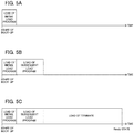
FIG. 5A] FIG. 5A is a diagram showing a time course of load of programs by the control portion shown inFIG. 1 . - [
FIG. 5B] FIG. 5B is a diagram showing the time course of load of the programs by the control portion shown inFIG. 1 . - [
FIG. 5C] FIG. 5C is a diagram showing the time course of load of the programs by the control portion shown inFIG. 1 . - [
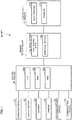
FIG. 6] FIG. 6 is a block diagram of the MFP shown inFIG. 1 at a time when boot-up is started. - [
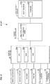
FIG. 7] FIG. 7 is a block diagram of the MFP shown inFIG. 1 when a reading speed is changed. - Hereinafter, an embodiment of the present invention will be described with reference to the drawings.
- First, the configuration of an MFP (multifunction peripheral) as an electronic apparatus according to the present embodiment will be described.
-
FIG. 1 is a block diagram of theMFP 10 according to the present embodiment. - As shown in
FIG. 1 , theMFP 10 includes: anoperation portion 11 that is an input device such as a button with which various operations are inputted; adisplay portion 12 that is a display device such as an LCD (liquid crystal display) which displays various types of information; ascanner 13 that is a reading device which reads an image from a document; aprinter 14 that is a printing device which executes printing on a recording medium such as a sheet; afax communication portion 15 that is a fax device which performs fax communication with an external facsimile apparatus, which is not shown, via a communication line such as a public telephone line; acommunication portion 16 that is a network communication device which performs communication with an external apparatus via a network such as a LAN (local area network); anon-volatile memory 17 such as a semiconductor memory, an HDD (hard disk drive), or the like which stores various types of information; amemory controller 18 that controls thenon-volatile memory 17; and acontrol portion 20 that controls the entirety of theMFP 10. - The
non-volatile memory 17 supports at least a first reading speed and a second reading speed higher than the first reading speed. For example, the first reading speed and the second reading speed are 500 KB/sec and 3.5 MB/sec, respectively. - The
non-volatile memory 17 has stored therein aboot program 17a andfirmware 17d. Each of theboot program 17a and thefirmware 17d may be installed into theMFP 10 during manufacture of theMFP 10, may be additionally installed into theMFP 10 from an external storage medium such as a CD, a DVD, an SD card, a USB (universal serial bus) memory, or the like, or may be additionally installed into theMFP 10 from a network. -
FIG. 2 is a diagram showing an example of theboot program 17a. - As shown in
FIG. 2 , theboot program 17a includes: aninitial load program 17b that is initially read by the memory controller 18 (seeFIG. 1 ) and loaded; and asubsequent load program 17c that is read by thememory controller 18 and loaded after theinitial load program 17b. - The
initial load program 17b is a program only for setting the reading speed of thememory controller 18 to the second reading speed. Theinitial load program 17b may be incorporated into hardware in the form of a microcode or the like. - The
subsequent load program 17c is a program for performing processing other than processing performed by execution of theinitial load program 17b, among processing performed by execution of theboot program 17a. - As shown in
FIG. 1 , thememory controller 18 has stored therein aninitial setting 18a as a reading speed. Thememory controller 18 sets, as theinitial setting 18a, a lowest first reading speed supported by various types of non-volatile memories among the reading speeds supported by thememory controller 18, such that various types of non-volatile memories that are mountable on theMFP 10 are enabled to be controlled. - The
memory controller 18 is capable of storing anadditional setting 18b as a reading speed. - The
control portion 20 includes, for example, a CPU (central processing unit) 20a, a ROM (read only memory) 20b that has stored therein programs and various types of data, and a RAM (random access memory) 20c that is used as a working area for theCPU 20a. TheCPU 20a executes a program stored in thenon-volatile memory 17 or theROM 20b. -
FIG. 3 is a block diagram of functions of thecontrol portion 20. - As shown in
FIG. 3 , thecontrol portion 20 functions as aboot loader 21 by executing theboot program 17a (seeFIG. 2 ). Specifically, thecontrol portion 20 functions as a (1st)boot loader 22 of theboot loader 21 by executing the loadedinitial load program 17b (seeFIG. 2 ), and functions as a (2nd)program loader 23 of theboot loader 21 by executing the loadedsubsequent load program 17c (seeFIG. 2 ). - The (1st)
boot loader 22 sets the reading speed of thememory controller 18 to the second reading speed and functions as a reading speed setting portion of the present invention. - The (2nd)
program loader 23 functions as: adevice setting portion 24 that performs setting of various devices such as theoperation portion 11, thedisplay portion 12, thescanner 13, theprinter 14, thefax communication portion 15, and thecommunication portion 16, etc.; and a firmwareload starting section 25 that starts load of thefirmware 17d. - Next, operation of the MFP 10 will be described.
-
FIG. 4 is a flowchart of an operation at boot-up of theMFP 10.FIG. 5 shows diagrams showing a time course of load of programs by thecontrol portion 20. - As shown in
FIG. 4 , when boot-up is started, thecontrol portion 20 causes thememory controller 18 to read theinitial load program 17b of theboot program 17a from thenon-volatile memory 17 and writes theinitial load program 17b read by thememory controller 18, into theRAM 20c, thereby loading theinitial load program 17b (S51) as shown inFIG. 5A . Here, since theadditional setting 18b (seeFIG. 1 ) has not been made as shown inFIG. 6 at the time when boot-up is started, thememory controller 18 reads theinitial load program 17b at the first reading speed of theinitial setting 18a. - Next, the (1st)
boot loader 22, which functions by thecontrol portion 20 executing the loadedinitial load program 17b, sets the reading speed of thememory controller 18 to the second reading speed as theadditional setting 18b (S52) as shown inFIG. 7 . Here, the (1st)boot loader 22 can set, as the second reading speed, the highest speed among the reading speeds supported by thenon-volatile memory 17 in which theboot program 17a is stored. - Next, the (1st)
boot loader 22 starts load of thesubsequent load program 17c (S53). - Accordingly, the
control portion 20 causes thememory controller 18 to read thesubsequent load program 17c of theboot program 17a from thenon-volatile memory 17 and writes thesubsequent load program 17c read by thememory controller 18, into theRAM 20c, thereby loading thesubsequent load program 17c (S54) as shown inFIG. 5B . Here, since theadditional setting 18b has been made as shown inFIG. 7 , thememory controller 18 reads thesubsequent load program 17c at the second reading speed of theadditional setting 18b. - Next, the
device setting portion 24 of the (2nd)program loader 23, which functions by thecontrol portion 20 executing the loadedsubsequent load program 17c, performs setting of various devices (S55). - Next, the firmware
load starting section 25 of the (2nd)program loader 23, which functions by thecontrol portion 20 executing the loadedsubsequent load program 17c, starts load of thefirmware 17d (S56). - Accordingly, the
control portion 20 causes thememory controller 18 to read thefirmware 17d from thenon-volatile memory 17 and writes thefirmware 17d read by thememory controller 18, into theRAM 20c, thereby loading thefirmware 17d (S57) as shown inFIG. 5C . Here, since theadditional setting 18b has been made as shown inFIG. 7 , thememory controller 18 reads thefirmware 17d at the second reading speed of theadditional setting 18b. - As described above, after the
MFP 10 sets, by causing thememory controller 18 to read theinitial load program 17b of theboot program 17a at the first reading speed of theinitial setting 18a and loading theinitial load program 17b (S51), the reading speed of thememory controller 18 to the second reading speed higher than the first reading speed (S52), theMFP 10 causes thememory controller 18 to read thesubsequent load program 17c of theboot program 17a different from theinitial load program 17b at the second reading speed and loads thesubsequent load program 17c (S54). Thus, theMFP 10 can shorten the time required for loading the entirety of theboot program 17a. - The case where, for example, the sizes of the
initial load program 17b and thesubsequent load program 17c are 4 KB and 124 KB, respectively, and the first reading speed and the second reading speed are 500 KB/sec and 3.5 MB/sec, respectively, will be described. - When the
memory controller 18 is caused to read the entirety of theboot program 17a at the first reading speed of theinitial setting 18a, the time required for loading the entirety of theboot program 17a is about 250 msec according to the following formula.
- Meanwhile, when the
memory controller 18 is caused to read theinitial load program 17b of theboot program 17a at the first reading speed of theinitial setting 18a and read thesubsequent load program 17c of theboot program 17a at the second reading speed of theadditional setting 18b, the time required for loading the entirety of theboot program 17a is about 45 msec according to the following formula.
- As shown in the above example, when the
memory controller 18 is caused to read theinitial load program 17b of theboot program 17a at the first reading speed of theinitial setting 18a and read thesubsequent load program 17c of theboot program 17a at the second reading speed of theadditional setting 18b, the time required for loading the entirety of theboot program 17a can be significantly shortened as compared to the case where thememory controller 18 is caused to read the entirety of theboot program 17a at the first reading speed of theinitial setting 18a. - The
MFP 10 can shorten the time required for loading the entirety of theboot program 17a. Thus, as a result, theMFP 10 can shorten a boot-up time. The case upon boot-up of theMFP 10 has been described above, but the same applies to a time when theMFP 10 returns from a power saving mode to a normal mode. That is, theMFP 10 can also shorten a return time from the power saving mode to the normal mode. - The
MFP 10 causes thememory controller 18 to read thefirmware 17d at the second reading speed and loads thefirmware 17d. Thus, theMFP 10 can also shorten the time required for loading thefirmware 17d. - The electronic apparatus of the present invention is the MFP in the present embodiment, but may be an image forming apparatus other than the MFP, such as a copying machine, a printer, a FAX apparatus, and a scanner, or may be an electronic apparatus other than the image forming apparatus, such as a personal computer (PC).
- In the electronic apparatus of the present invention, the subsequent load program may be at least a program for starting load of firmware, and the firmware may be stored in the non-volatile memory.
- With this configuration, the electronic apparatus of the present invention causes the memory controller to read the firmware at the second reading speed and loads the firmware, and thus can shorten the time required for loading the firmware.
- In the electronic apparatus of the present invention, the first reading speed is the lowest speed supported by the non-volatile memory among the reading speeds supported by the memory controller, and the second reading speed is the highest speed among the reading speeds supported by the non-volatile memory.
- In addition, the boot program according to the present invention is a boot program executed by an electronic apparatus including: a non-volatile memory supporting at least a first reading speed and a second reading speed higher than the first reading speed and that stores the boot program; and a memory controller for which the first reading speed is initially set, the boot program including an initial load program that is initially read by the memory controller and loaded and a subsequent load program that is read by the memory controller and loaded after the initial load program, wherein the electronic apparatus is caused to function as a reading speed setting portion that sets a reading speed of the memory controller to the second reading speed, by the loaded initial load program being executed by the electronic apparatus.
- With this configuration, the electronic apparatus of the present invention is capable of controlling various types of non-volatile memories that are mountable on the electronic apparatus, at the lowest speed, and causes the memory controller to read the subsequent load program at the highest speed and loads the subsequent load program. Thus, the electronic apparatus can shorten the time required for loading the entirety of the boot program.
Claims (3)
- An electronic apparatus comprising:a non-volatile memory supporting at least a first reading speed and a second reading speed higher than the first reading speed and that stores a boot program; anda memory controller for which the first reading speed is initially set, whereinthe boot program includes an initial load program that is initially read by the memory controller and loaded, and a subsequent load program that is read by the memory controller and loaded after the initial load program, andthe electronic apparatus functions as a reading speed setting portion that sets a reading speed of the memory controller to the second reading speed, by executing the loaded initial load program.
- The electronic apparatus according to claim 1, wherein
the subsequent load program is at least a program for starting load of firmware, and
the firmware is stored in the non-volatile memory. - The electronic apparatus according to claim 1, wherein
the first reading speed is a lowest speed supported by the non-volatile memory among reading speeds supported by the memory controller, and
the second reading speed is a highest speed among reading speeds supported by the non-volatile memory.
Applications Claiming Priority (2)
| Application Number | Priority Date | Filing Date | Title |
|---|---|---|---|
| JP2015151954 | 2015-07-31 | ||
| PCT/JP2016/065162 WO2017022300A1 (en) | 2015-07-31 | 2016-05-23 | Electronic device |
Publications (2)
| Publication Number | Publication Date |
|---|---|
| EP3330849A1 true EP3330849A1 (en) | 2018-06-06 |
| EP3330849A4 EP3330849A4 (en) | 2018-07-25 |
Family
ID=57942844
Family Applications (1)
| Application Number | Title | Priority Date | Filing Date |
|---|---|---|---|
| EP16790508.2A Withdrawn EP3330849A4 (en) | 2015-07-31 | 2016-05-23 | Electronic device |
Country Status (5)
| Country | Link |
|---|---|
| US (1) | US20170177376A1 (en) |
| EP (1) | EP3330849A4 (en) |
| JP (1) | JP6104481B1 (en) |
| CN (1) | CN106664347A (en) |
| WO (1) | WO2017022300A1 (en) |
Families Citing this family (2)
| Publication number | Priority date | Publication date | Assignee | Title |
|---|---|---|---|---|
| JP7242233B2 (en) * | 2018-09-28 | 2023-03-20 | キヤノン株式会社 | Information processing device and its control method and program |
| CN116501401A (en) * | 2022-01-18 | 2023-07-28 | 北京有竹居网络技术有限公司 | Program loading method, device, computer readable medium and electronic device |
Family Cites Families (10)
| Publication number | Priority date | Publication date | Assignee | Title |
|---|---|---|---|---|
| JPS63153635A (en) * | 1986-09-16 | 1988-06-27 | Hitachi Ltd | Specification system for data transfer speed |
| US20060009336A1 (en) * | 2004-07-08 | 2006-01-12 | Millet Juan D | Wing-T |
| US7522840B2 (en) * | 2004-10-29 | 2009-04-21 | Finisar Corporation | Adjustable boot speed in an optical transceiver |
| JP2008134736A (en) * | 2006-11-27 | 2008-06-12 | Fujifilm Corp | Electronics |
| TWI378384B (en) * | 2008-10-15 | 2012-12-01 | Phison Electronics Corp | Mother board system, storage device for booting up thereof and connector |
| JP2012015812A (en) * | 2010-06-30 | 2012-01-19 | Kyocera Mita Corp | Image formation device |
| JP5200085B2 (en) | 2010-11-04 | 2013-05-15 | レノボ・シンガポール・プライベート・リミテッド | Method and computer for starting computer in a short time |
| JP2013246630A (en) | 2012-05-25 | 2013-12-09 | Panasonic Corp | Boot system and system initializing method |
| JP2015022516A (en) * | 2013-07-19 | 2015-02-02 | ソニー株式会社 | Storage control device, storage device, information processing system, and storage control method |
| JP5996513B2 (en) * | 2013-11-27 | 2016-09-21 | 京セラドキュメントソリューションズ株式会社 | Electronics |
-
2016
- 2016-05-23 WO PCT/JP2016/065162 patent/WO2017022300A1/en not_active Ceased
- 2016-05-23 JP JP2016567435A patent/JP6104481B1/en not_active Expired - Fee Related
- 2016-05-23 EP EP16790508.2A patent/EP3330849A4/en not_active Withdrawn
- 2016-05-23 CN CN201680001378.0A patent/CN106664347A/en active Pending
- 2016-05-23 US US15/311,167 patent/US20170177376A1/en not_active Abandoned
Also Published As
| Publication number | Publication date |
|---|---|
| WO2017022300A1 (en) | 2017-02-09 |
| US20170177376A1 (en) | 2017-06-22 |
| CN106664347A (en) | 2017-05-10 |
| JPWO2017022300A1 (en) | 2017-08-03 |
| JP6104481B1 (en) | 2017-03-29 |
| EP3330849A4 (en) | 2018-07-25 |
Similar Documents
| Publication | Publication Date | Title |
|---|---|---|
| US9507584B2 (en) | Electronic device including a memory technology device | |
| US9524177B2 (en) | Information processing apparatus, method for controlling information processing apparatus, and storage medium | |
| US11327769B2 (en) | Control device, image forming apparatus, and start-up method thereof | |
| US20190095259A1 (en) | Electronic Device and Log Application | |
| US9454386B2 (en) | Image forming apparatus and method that realize function by installed application | |
| EP3293626A1 (en) | Information processing apparatus and method of controlling the same | |
| US20150062613A1 (en) | Image forming apparatus capable of preventing data leakage and control method therefor, and storage medium | |
| US20170177376A1 (en) | Electronic apparatus | |
| US10356256B2 (en) | Communication apparatus, control method for communication apparatus, and storage medium for changing a version of an encryption communication protocol used for communication | |
| US20180115675A1 (en) | Image forming apparatus that installs applications, control method therefor, and storage medium | |
| US9348295B2 (en) | Printing apparatus, method for controlling printing apparatus, and storage medium | |
| US20110157645A1 (en) | Image forming apparatus, method for controlling image forming apparatus, and storage medium | |
| US9652304B2 (en) | Electronic apparatus that uses program from another program working on different platforms, and method | |
| JP5996513B2 (en) | Electronics | |
| US20180146111A1 (en) | Image forming apparatus, control method therefor, and storage medium | |
| US9626143B2 (en) | Image forming device that improves usage efficiency of memory, management method, and recording medium | |
| US12474860B2 (en) | Information processing apparatus, control method of information processing apparatus, and non-transitory storage medium | |
| US10701237B2 (en) | Information processing apparatus and data storage program | |
| US10437488B2 (en) | Electronic device and non-transitory computer readable storage medium | |
| JP6414554B2 (en) | Image forming apparatus and data processing program | |
| US9930201B2 (en) | Image forming apparatus | |
| US8643860B2 (en) | Image forming apparatus performing network communication | |
| US20200174876A1 (en) | Electronic apparatus equipped with hdd, control method therefor, and storage medium | |
| EP3101550B1 (en) | Image formation device and image formation method | |
| JP6169026B2 (en) | Electronic device and display control program |
Legal Events
| Date | Code | Title | Description |
|---|---|---|---|
| PUAI | Public reference made under article 153(3) epc to a published international application that has entered the european phase |
Free format text: ORIGINAL CODE: 0009012 |
|
| 17P | Request for examination filed |
Effective date: 20161114 |
|
| AK | Designated contracting states |
Kind code of ref document: A1 Designated state(s): AL AT BE BG CH CY CZ DE DK EE ES FI FR GB GR HR HU IE IS IT LI LT LU LV MC MK MT NL NO PL PT RO RS SE SI SK SM TR |
|
| AX | Request for extension of the european patent |
Extension state: BA ME |
|
| A4 | Supplementary search report drawn up and despatched |
Effective date: 20180626 |
|
| RIC1 | Information provided on ipc code assigned before grant |
Ipc: G06F 9/4401 20180101ALI20180620BHEP Ipc: G06F 12/06 20060101ALI20180620BHEP Ipc: G06F 9/445 20180101AFI20180620BHEP |
|
| DAV | Request for validation of the european patent (deleted) | ||
| DAX | Request for extension of the european patent (deleted) | ||
| 17Q | First examination report despatched |
Effective date: 20190215 |
|
| STAA | Information on the status of an ep patent application or granted ep patent |
Free format text: STATUS: THE APPLICATION IS DEEMED TO BE WITHDRAWN |
|
| 18D | Application deemed to be withdrawn |
Effective date: 20200207 |