EP3330761B1 - Fan-out joint for fiberoptic cables - Google Patents
Fan-out joint for fiberoptic cables Download PDFInfo
- Publication number
- EP3330761B1 EP3330761B1 EP17205563.4A EP17205563A EP3330761B1 EP 3330761 B1 EP3330761 B1 EP 3330761B1 EP 17205563 A EP17205563 A EP 17205563A EP 3330761 B1 EP3330761 B1 EP 3330761B1
- Authority
- EP
- European Patent Office
- Prior art keywords
- tube
- fiberoptic
- cables
- splice joint
- splice
- Prior art date
- Legal status (The legal status is an assumption and is not a legal conclusion. Google has not performed a legal analysis and makes no representation as to the accuracy of the status listed.)
- Active
Links
Images


Classifications
-
- G—PHYSICS
- G02—OPTICS
- G02B—OPTICAL ELEMENTS, SYSTEMS OR APPARATUS
- G02B6/00—Light guides; Structural details of arrangements comprising light guides and other optical elements, e.g. couplings
- G02B6/24—Coupling light guides
- G02B6/36—Mechanical coupling means
- G02B6/38—Mechanical coupling means having fibre to fibre mating means
- G02B6/3807—Dismountable connectors, i.e. comprising plugs
- G02B6/381—Dismountable connectors, i.e. comprising plugs of the ferrule type, e.g. fibre ends embedded in ferrules, connecting a pair of fibres
- G02B6/3817—Dismountable connectors, i.e. comprising plugs of the ferrule type, e.g. fibre ends embedded in ferrules, connecting a pair of fibres containing optical and electrical conductors
-
- G—PHYSICS
- G02—OPTICS
- G02B—OPTICAL ELEMENTS, SYSTEMS OR APPARATUS
- G02B6/00—Light guides; Structural details of arrangements comprising light guides and other optical elements, e.g. couplings
- G02B6/44—Mechanical structures for providing tensile strength and external protection for fibres, e.g. optical transmission cables
- G02B6/4439—Auxiliary devices
- G02B6/4471—Terminating devices ; Cable clamps
- G02B6/44715—Fan-out devices
-
- G—PHYSICS
- G02—OPTICS
- G02B—OPTICAL ELEMENTS, SYSTEMS OR APPARATUS
- G02B6/00—Light guides; Structural details of arrangements comprising light guides and other optical elements, e.g. couplings
- G02B6/24—Coupling light guides
- G02B6/255—Splicing of light guides, e.g. by fusion or bonding
- G02B6/2558—Reinforcement of splice joint
-
- G—PHYSICS
- G02—OPTICS
- G02B—OPTICAL ELEMENTS, SYSTEMS OR APPARATUS
- G02B6/00—Light guides; Structural details of arrangements comprising light guides and other optical elements, e.g. couplings
- G02B6/24—Coupling light guides
- G02B6/36—Mechanical coupling means
- G02B6/38—Mechanical coupling means having fibre to fibre mating means
- G02B6/3807—Dismountable connectors, i.e. comprising plugs
- G02B6/3833—Details of mounting fibres in ferrules; Assembly methods; Manufacture
- G02B6/3855—Details of mounting fibres in ferrules; Assembly methods; Manufacture characterised by the method of anchoring or fixing the fibre within the ferrule
- G02B6/3861—Adhesive bonding
-
- G—PHYSICS
- G02—OPTICS
- G02B—OPTICAL ELEMENTS, SYSTEMS OR APPARATUS
- G02B6/00—Light guides; Structural details of arrangements comprising light guides and other optical elements, e.g. couplings
- G02B6/44—Mechanical structures for providing tensile strength and external protection for fibres, e.g. optical transmission cables
- G02B6/4439—Auxiliary devices
- G02B6/4471—Terminating devices ; Cable clamps
- G02B6/4472—Manifolds
-
- G—PHYSICS
- G02—OPTICS
- G02B—OPTICAL ELEMENTS, SYSTEMS OR APPARATUS
- G02B6/00—Light guides; Structural details of arrangements comprising light guides and other optical elements, e.g. couplings
- G02B6/44—Mechanical structures for providing tensile strength and external protection for fibres, e.g. optical transmission cables
- G02B6/4439—Auxiliary devices
- G02B6/444—Systems or boxes with surplus lengths
- G02B6/44528—Patch-cords; Connector arrangements in the system or in the box
-
- G—PHYSICS
- G02—OPTICS
- G02B—OPTICAL ELEMENTS, SYSTEMS OR APPARATUS
- G02B6/00—Light guides; Structural details of arrangements comprising light guides and other optical elements, e.g. couplings
- G02B6/44—Mechanical structures for providing tensile strength and external protection for fibres, e.g. optical transmission cables
- G02B6/4439—Auxiliary devices
- G02B6/4471—Terminating devices ; Cable clamps
- G02B6/44765—Terminating devices ; Cable clamps with means for strain-relieving to exterior cable layers
Definitions
- the present invention relates generally to optical fiber communications, and particularly to fiberoptic cables and methods for their production.
- Fiberoptic cables commonly contain multiple fibers bundled together in an outer protective jacket. At the ends of the cable, all of the fibers may be connected to respective pins of a single optical connector, but in some cases, the fibers in the cable are fanned out into multiple, separate terminations, each with its own connector. Typically, after fanning out the fibers from the main cable, the fibers that are to be attached to each connector are fed through a separate protective jacket of their own. This process generally limits the fan-out point to locations near the end of the cable.
- U.S. Patent Publication No. 8737786B1 discloses a fiber optic cable assembly includes leg assemblies, a trunk assembly, a splice assembly, and a furcation assembly.
- U.S. Patent Application Publication No. 2016/049782 discloses a cable breakout assembly comprising a plurality of environmentally sealed, flexible conduits extending from a multi-port gland.
- U.S. Patent Application Publication No. 2011/262084 discloses a fiber optic cable assembly including a main fiber optic cable and a pre-connectorized fiber optic cable assembly.
- U.S. Patent Application Publication No. 2005/265672 discloses a fiber optic distribution cable having articulated optical connection nodes.
- a method for producing a fiberoptic fan-out which includes creating a splice joint between a first fiberoptic cable and two or more second fiberoptic cables, such that at the splice joint, each of a plurality of first optical fibers in the first fiberoptic cable is spliced to a respective second optical fiber in one of the second fiberoptic cables, wherein creating the splice joint comprises fitting a tubular splice protector over the splice joint.
- a tube slides over the cables to a position at which the splice joint is contained inside the tube, wherein the tube contains an internal shoulder, and wherein sliding the tube comprises sliding the tubular splice protector into the tube until an end of the tubular splice protector engages the internal shoulder. While the splice joint is contained inside the tube, the tube is filled with a fixative so as to fix the splice joint in the position.
- the first and second fiberoptic cables have respective first and second ends, wherein the first ends of the first and second fiberoptic cables are joined together at the splice joint, and the method includes terminating the second end of the first fiberoptic cable with a first connector of a first type, and terminating the second ends of the second fiberoptic cables with second connectors of a second type, different from the first type.
- the tube includes an outer wall enclosing an inner lumen into which the splice joint is inserted and having one or more holes formed transversely through the outer wall into the inner lumen, and filling the tube includes injecting the fixative through the one or more holes.
- the fixative includes an epoxy, which is injected through the one or more holes in a fluid form and hardens inside the tube.
- the tube has first and second ends, through which the first and second cables respectively protrude after positioning the splice joint inside the tube, and the method includes attaching first and second strain-relief boots, fitting over the first and second cables, respectively, to the first and second ends of the tube.
- the two or more second fiberoptic cables include four second fiberoptic cables, which are joined to the first fiberoptic cable at the splice joint.
- fiberoptic apparatus including a first fiberoptic cable, including a plurality of first optical fibers, and two or more second fiberoptic cables, including second optical fibers.
- first optical fibers in the first fiberoptic cable is spliced at a splice joint to a respective second optical fiber in one of the second fiberoptic cables.
- a tube is fitted over the cables and containing the splice joint inside the tube, and a fixative fills the tube so as to fix the splice joint in position in the tube.
- the apparatus comprise a tubular splice protector, which fits over the first and second optical fibers and is contained inside the tube.
- the tube comprises an internal shoulder, which engages an end of the tubular splice protector inside the tube.
- the tube may comprise an outer wall enclosing an inner lumen into which the splice joint is inserted and having one or more holes formed transversely through the outer wall into the inner lumen, wherein the fixative is injected into the tube through the one or more holes.
- the fixative may comprise an epoxy, which is injected through the one or more holes in a fluid form and hardens inside the tube.
- the tube may have first and second ends, through which the first and second cables respectively protrude after positioning the splice joint inside the tube, and the apparatus may comprise first and second strain-relief boots, fitting over the first and second cables, respectively, and attached to the first and second ends of the tube.
- the two or more second fiberoptic cables may comprise four second fiberoptic cables, which are joined to the first fiberoptic cable at the splice joint.
- Embodiments of the present invention that are described herein provide novel methods for fabrication of fan-out cables, as well as cables produced by such methods. These methods make it practical to create a reliable fan-out joint anywhere along the length of a cable, without limitation to locations near the ends of the cable as in methods that are known in the art.
- a cable of this sort can thus be connected, for example, to a single, multi-pin communication socket at one end, while fanning out at the other end to connect to multiple smaller sockets in different locations, which may be spaced several meters apart.
- a splice joint is created between a multi-fiber fiberoptic cable and two or more smaller fiberoptic cables.
- each of the optical fibers in the multi-fiber fiberoptic cable is spliced to a respective optical fiber in one of the smaller fiberoptic cables.
- a special-purpose tube referred to in the description that follows as a "fan-out tube,” is slid over the cables to a position at which the splice joint is contained inside the tube. With the splice joint in position inside the tube, the tube is filled with a fixative, such as a suitable epoxy, which fixes the splice joint in position.
- Fig. 1 is a schematic pictorial illustration of a fiberoptic cable 20 of this sort with a fan-out assembly 22, in accordance with an embodiment of the invention.
- cable 20 comprises an eight-fiber cable 24, which terminates in a multi-pin connector 26 at one end (such as an SFP-type connector).
- the ends of the optical fibers in cable 24 are spliced within fan-out assembly 22 to the ends of corresponding fibers in four two-fiber cables 30, which terminate in respective passive optical connectors 32.
- Cables 30 may be contained together in a protective jacket over a part of their lengths, but the use and extent of such a jacket are optional.
- Fig. 1 certain particular types and numbers of cables and their respective terminations are shown in Fig. 1 only by way of example; and the components and techniques that are described herein may be applied, mutatis mutandis, in creating fan-outs between substantially any suitable types of fiberoptic cables with any numbers of optical fibers.
- FIG. 2A is an exploded view of the components of the fan-out assembly
- Fig. 2B shows details of a splice joint in assembly 22.
- each optical fiber 42 in cable 24 is connected to a corresponding fiber 44 in one of cables 30.
- These splice connections can be made using techniques that are well known in the art, such as fusion splicing, with tools that are commercially available from various vendors.
- a tubular splice protector 40 is slid over the splice joint.
- Splice protector 40 typically comprises a plastic tube with a stiffening member to avoid excessive bending of the spliced fibers.
- splice protector 40 may comprise an inner tube made from a meltable adhesive, such as ethylene vinyl acetate (EVA), which is contained, together with a stainless steel stiffening wire, inside an outer tube made from a heat-shrinkable plastic, such as polyolefin. After this splice protector is slid over the splice joint, it is heated to activate the inner tube adhesive and shrink the outer tube to fit tightly over the splice and stiffening wire. Splice protectors of this sort are available from various vendors, and the details of their design are beyond the scope of the present disclosure.
- a meltable adhesive such as ethylene vinyl acetate (EVA)
- EVA ethylene vinyl acetate
- a fan-out tube 46 is slid over cables 24 and 30 to a position at which splice protector 40 is contained inside tube 46.
- a shoulder 54 inside tube 46 ensures that splice protector 40 stops at precisely the correct location within tube 46 and does not inadvertently pass through to the other side.
- Fan-out tube 46 is then filled with a fixative, such as a suitable epoxy, to fix splice protector 40 permanently in place and fix all of the cables together to the fan-out tube.
- Strain relief boots 48 and 49 are fitted over cables 24 and 30 (which protrude respectively from the two ends of fan-out tube 46) to the ends of the fan-out tube.
- Boot 49 in the present example has a larger inner diameter than boot 48, since boot 48 accommodates only the single cable 24, while boot 49 accommodates all four of cables 30.
- Boots 48 and 49 prevent possible damage to the optical fibers that could otherwise result due to unintended bending of cables 24 and 30 against the ends of the fan-out tube.
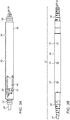
- Figs. 3A is a schematic side view, with a partial cutaway, of fan-out tube 46 with splice protector 40 fitted inside, in accordance with an embodiment of the invention.
- the inner lumen of fan-out tube 46 is designed to snugly contain splice protector 40.
- tube 46 contains internal shoulder 54, with a smaller diameter than splice protector 40.
- the splice protector is slid into fan-out tube 46 (from the right side in the view shown in Fig. 3A ) until the end of the splice protector engages shoulder 54. This shoulder thus ensures that the splice joint will be properly positioned inside tube 46.
- Fig. 3B is a schematic side view of fan-out assembly 22 (with fan-out tube 46 rotated by 90° relative to the view shown in Fig. 3A ), in accordance with an embodiment of the invention.
- Fan-out tube 46 has a number of holes 50 that are formed transversely through the outer wall of the tube to the inner lumen where splice protector 40 is contained.
- a fixative such as an epoxy, is injected through holes 50 in fluid form and hardens inside, thus fixing splice protector 40 and cables 24 and 30 in place.
- the fixative is typically injected through a nozzle or nozzles (not shown) that fit tightly into holes 50, so that the fixative spreads evenly through the inner lumen without leaking out.
- fan-out tube 46 may be heated after injection of the fixative for the purpose of thermal curing.
- Strain-relief boots 48 and 49 are fitted over external shoulders 52 at the ends of tube 46 ( Fig. 3A ), either before or after fixation of splice protector 40 inside the tube.
Landscapes
- Physics & Mathematics (AREA)
- General Physics & Mathematics (AREA)
- Optics & Photonics (AREA)
- Engineering & Computer Science (AREA)
- Plasma & Fusion (AREA)
- Light Guides In General And Applications Therefor (AREA)
- Processing Of Terminals (AREA)
- Media Introduction/Drainage Providing Device (AREA)
Description
- The present invention relates generally to optical fiber communications, and particularly to fiberoptic cables and methods for their production.
- Fiberoptic cables commonly contain multiple fibers bundled together in an outer protective jacket. At the ends of the cable, all of the fibers may be connected to respective pins of a single optical connector, but in some cases, the fibers in the cable are fanned out into multiple, separate terminations, each with its own connector. Typically, after fanning out the fibers from the main cable, the fibers that are to be attached to each connector are fed through a separate protective jacket of their own. This process generally limits the fan-out point to locations near the end of the cable.
-
U.S. Patent Publication No. 8737786B1 discloses a fiber optic cable assembly includes leg assemblies, a trunk assembly, a splice assembly, and a furcation assembly. -
U.S. Patent Application Publication No. 2016/049782 discloses a cable breakout assembly comprising a plurality of environmentally sealed, flexible conduits extending from a multi-port gland. -
U.S. Patent Application Publication No. 2011/262084 discloses a fiber optic cable assembly including a main fiber optic cable and a pre-connectorized fiber optic cable assembly. -
U.S. Patent Application Publication No. 2005/265672 discloses a fiber optic distribution cable having articulated optical connection nodes. - Aspects and embodiments of the present invention are set out in the appended claims. These and other aspects and embodiments of the invention are also described herein. Embodiments of the present invention that are described hereinbelow provide improved methods for production of fiberoptic cables, as well as cables produced by such methods.
- There is therefore provided, in accordance with an embodiment of the invention, a method for producing a fiberoptic fan-out, which includes creating a splice joint between a first fiberoptic cable and two or more second fiberoptic cables, such that at the splice joint, each of a plurality of first optical fibers in the first fiberoptic cable is spliced to a respective second optical fiber in one of the second fiberoptic cables, wherein creating the splice joint comprises fitting a tubular splice protector over the splice joint. A tube slides over the cables to a position at which the splice joint is contained inside the tube, wherein the tube contains an internal shoulder, and wherein sliding the tube comprises sliding the tubular splice protector into the tube until an end of the tubular splice protector engages the internal shoulder. While the splice joint is contained inside the tube, the tube is filled with a fixative so as to fix the splice joint in the position.
- In a disclosed embodiment, the first and second fiberoptic cables have respective first and second ends, wherein the first ends of the first and second fiberoptic cables are joined together at the splice joint, and the method includes terminating the second end of the first fiberoptic cable with a first connector of a first type, and terminating the second ends of the second fiberoptic cables with second connectors of a second type, different from the first type.
- Additionally or alternatively, the tube includes an outer wall enclosing an inner lumen into which the splice joint is inserted and having one or more holes formed transversely through the outer wall into the inner lumen, and filling the tube includes injecting the fixative through the one or more holes. In a disclosed embodiment, the fixative includes an epoxy, which is injected through the one or more holes in a fluid form and hardens inside the tube.
- Further additionally or alternatively, the tube has first and second ends, through which the first and second cables respectively protrude after positioning the splice joint inside the tube, and the method includes attaching first and second strain-relief boots, fitting over the first and second cables, respectively, to the first and second ends of the tube.
- In one embodiment, the two or more second fiberoptic cables include four second fiberoptic cables, which are joined to the first fiberoptic cable at the splice joint.
- There is also provided, in accordance with an embodiment of the invention, fiberoptic apparatus, including a first fiberoptic cable, including a plurality of first optical fibers, and two or more second fiberoptic cables, including second optical fibers. Each of the first optical fibers in the first fiberoptic cable is spliced at a splice joint to a respective second optical fiber in one of the second fiberoptic cables. A tube is fitted over the cables and containing the splice joint inside the tube, and a fixative fills the tube so as to fix the splice joint in position in the tube.
- The apparatus comprise a tubular splice protector, which fits over the first and second optical fibers and is contained inside the tube. The tube comprises an internal shoulder, which engages an end of the tubular splice protector inside the tube.
- The tube may comprise an outer wall enclosing an inner lumen into which the splice joint is inserted and having one or more holes formed transversely through the outer wall into the inner lumen, wherein the fixative is injected into the tube through the one or more holes.
- The fixative may comprise an epoxy, which is injected through the one or more holes in a fluid form and hardens inside the tube.
- The tube may have first and second ends, through which the first and second cables respectively protrude after positioning the splice joint inside the tube, and the apparatus may comprise first and second strain-relief boots, fitting over the first and second cables, respectively, and attached to the first and second ends of the tube.
- The two or more second fiberoptic cables may comprise four second fiberoptic cables, which are joined to the first fiberoptic cable at the splice joint.
- The present invention will be more fully understood from the following detailed description of the embodiments thereof, taken together with the drawings in which:
-
-
Fig. 1 is a schematic pictorial illustration of a fiberoptic cable, in accordance with an embodiment of the invention; -
Fig. 2A is a schematic, exploded view of the components of a fan-out assembly incorporated in a fiberoptic cable, in accordance with an embodiment of the invention; -
Fig. 2B is a schematic detail view of a splice joint in the fan-out assembly ofFig. 2A ; -
Fig. 3A is a schematic side view, with a partial cutaway, of a fan-out tube used in a fiberoptic cable, in accordance with an embodiment of the invention; and -
Fig. 3B is a schematic side view of a fan-out assembly incorporating the fan-out tube ofFig. 3A , in accordance with an embodiment of the invention. - Embodiments of the present invention that are described herein provide novel methods for fabrication of fan-out cables, as well as cables produced by such methods. These methods make it practical to create a reliable fan-out joint anywhere along the length of a cable, without limitation to locations near the ends of the cable as in methods that are known in the art. A cable of this sort can thus be connected, for example, to a single, multi-pin communication socket at one end, while fanning out at the other end to connect to multiple smaller sockets in different locations, which may be spaced several meters apart.
- In the disclosed methods, a splice joint is created between a multi-fiber fiberoptic cable and two or more smaller fiberoptic cables. At the splice joint, each of the optical fibers in the multi-fiber fiberoptic cable is spliced to a respective optical fiber in one of the smaller fiberoptic cables. A special-purpose tube, referred to in the description that follows as a "fan-out tube," is slid over the cables to a position at which the splice joint is contained inside the tube. With the splice joint in position inside the tube, the tube is filled with a fixative, such as a suitable epoxy, which fixes the splice joint in position.
-
Fig. 1 is a schematic pictorial illustration of afiberoptic cable 20 of this sort with a fan-out assembly 22, in accordance with an embodiment of the invention. In this example,cable 20 comprises an eight-fiber cable 24, which terminates in amulti-pin connector 26 at one end (such as an SFP-type connector). The ends of the optical fibers incable 24 are spliced within fan-out assembly 22 to the ends of corresponding fibers in four two-fiber cables 30, which terminate in respective passiveoptical connectors 32.Cables 30 may be contained together in a protective jacket over a part of their lengths, but the use and extent of such a jacket are optional. - More generally speaking, certain particular types and numbers of cables and their respective terminations are shown in
Fig. 1 only by way of example; and the components and techniques that are described herein may be applied, mutatis mutandis, in creating fan-outs between substantially any suitable types of fiberoptic cables with any numbers of optical fibers. - Reference is now made to
Figs. 2A and 2B , which schematically show details of fan-out assembly 22, in accordance with an embodiment of the invention.Fig. 2A is an exploded view of the components of the fan-out assembly, whileFig. 2B shows details of a splice joint inassembly 22. - At the splice joint, each
optical fiber 42 incable 24 is connected to acorresponding fiber 44 in one ofcables 30. These splice connections can be made using techniques that are well known in the art, such as fusion splicing, with tools that are commercially available from various vendors. Afterfibers tubular splice protector 40 is slid over the splice joint.Splice protector 40 typically comprises a plastic tube with a stiffening member to avoid excessive bending of the spliced fibers. For example,splice protector 40 may comprise an inner tube made from a meltable adhesive, such as ethylene vinyl acetate (EVA), which is contained, together with a stainless steel stiffening wire, inside an outer tube made from a heat-shrinkable plastic, such as polyolefin. After this splice protector is slid over the splice joint, it is heated to activate the inner tube adhesive and shrink the outer tube to fit tightly over the splice and stiffening wire. Splice protectors of this sort are available from various vendors, and the details of their design are beyond the scope of the present disclosure. - After fitting
splice protector 40 over the splice joint, a fan-outtube 46 is slid overcables protector 40 is contained insidetube 46. In the present embodiment, ashoulder 54 inside tube 46 (shown inFig. 3A ) ensures thatsplice protector 40 stops at precisely the correct location withintube 46 and does not inadvertently pass through to the other side. Fan-outtube 46 is then filled with a fixative, such as a suitable epoxy, to fixsplice protector 40 permanently in place and fix all of the cables together to the fan-out tube. Strain relief boots 48 and 49 are fitted overcables 24 and 30 (which protrude respectively from the two ends of fan-out tube 46) to the ends of the fan-out tube. (Boot 49 in the present example has a larger inner diameter thanboot 48, sinceboot 48 accommodates only thesingle cable 24, whileboot 49 accommodates all four ofcables 30.)Boots cables -
Figs. 3A is a schematic side view, with a partial cutaway, of fan-outtube 46 withsplice protector 40 fitted inside, in accordance with an embodiment of the invention. The inner lumen of fan-outtube 46 is designed to snugly containsplice protector 40. As noted earlier,tube 46 containsinternal shoulder 54, with a smaller diameter thansplice protector 40. After splicingfibers fitting splice protector 40 over the splice joint, the splice protector is slid into fan-out tube 46 (from the right side in the view shown inFig. 3A ) until the end of the splice protector engagesshoulder 54. This shoulder thus ensures that the splice joint will be properly positioned insidetube 46. -
Fig. 3B is a schematic side view of fan-out assembly 22 (with fan-outtube 46 rotated by 90° relative to the view shown inFig. 3A ), in accordance with an embodiment of the invention. Fan-outtube 46 has a number ofholes 50 that are formed transversely through the outer wall of the tube to the inner lumen wheresplice protector 40 is contained. A fixative, such as an epoxy, is injected throughholes 50 in fluid form and hardens inside, thus fixingsplice protector 40 andcables holes 50, so that the fixative spreads evenly through the inner lumen without leaking out. Optionally, fan-outtube 46 may be heated after injection of the fixative for the purpose of thermal curing. - Strain-
relief boots external shoulders 52 at the ends of tube 46 (Fig. 3A ), either before or after fixation ofsplice protector 40 inside the tube. - It will be appreciated that the embodiments described above are cited by way of example, and that the present invention is not limited to what has been particularly shown and described hereinabove. Rather, the scope of the present invention includes both combinations and subcombinations of the various features described hereinabove, as well as variations and modifications thereof which would occur to persons skilled in the art upon reading the foregoing description and which are not disclosed in the prior art.
- It will be understood that the invention has been described above purely by way of example, and modifications of detail can be made within the scope of the invention.
- Each feature disclosed in the description, and (where appropriate) the claims and drawings may be provided independently or in any appropriate combination.
- Reference numerals appearing in the claims are by way of illustration only and shall have no limiting effect on the scope of the claims.
Claims (12)
- A method for producing a fiberoptic fan-out, comprising:creating a splice joint between a first fiberoptic cable (24) and two or more second fiberoptic cables (42), such that at the splice joint, each of a plurality of first optical fibers (42) in the first fiberoptic cable is spliced to a respective second optical fiber (44) in one of the second fiberoptic cables, wherein creating the splice joint comprises fitting a tubular splice protector (40) over the splice joint;sliding a tube (46) over the cables to a position at which the splice joint is contained inside the tube, wherein the tube contains an internal shoulder (54), and wherein sliding the tube comprises sliding the tubular splice protector into the tube until an end of the tubular splice protector engages the internal shoulder; andwhile the splice joint is contained inside the tube, filling the tube with a fixative so as to fix the splice joint in the position.
- The method according to claim 1, wherein the first and second fiberoptic cables (24, 30) have respective first and second ends, wherein the first ends of the first and second fiberoptic cables are joined together at the splice joint, and
wherein the method comprises terminating the second end of the first fiberoptic cable (24) with a first connector (26) of a first type, and terminating the second ends of the second fiberoptic cables (30) with second connectors (32) of a second type, different from the first type. - The method according to any preceding claim, wherein the tube (46) comprises an outer wall enclosing an inner lumen into which the splice joint is inserted and having one or more holes (50) formed transversely through the outer wall into the inner lumen, and wherein filling the tube comprises injecting the fixative through the one or more holes.
- The method according to claim 3, wherein the fixative comprises an epoxy, which is injected through the one or more holes (50) in a fluid form and hardens inside the tube.
- The method according to any preceding claim, wherein the tube (46) has first and second ends, through which the first and second cables (24, 30) respectively protrude after positioning the splice joint inside the tube, and wherein the method comprises attaching first and second strain-relief boots (48, 49), fitting over the first and second cables, respectively, to the first and second ends of the tube.
- The method according to any preceding claim, wherein the two or more second fiberoptic cables (30) comprise four second fiberoptic cables, which are joined to the first fiberoptic cable (24) at the splice joint.
- Fiberoptic apparatus (20), comprising:a first fiberoptic cable (24), comprising a plurality of first optical fibers (42);two or more second fiberoptic cables (30), comprising second optical fibers (44);a splice joint, at which each of the first optical fibers in the first fiberoptic cable is spliced to a respective second optical fiber in one of the second fiberoptic cables;a tubular splice protector (40), which fits over the first and second optical fibers (42, 44);a tube (46) fitted over the cables and containing the splice joint inside the tube, wherein the tube comprises an internal shoulder (54), which engages an end of the tubular splice protector inside the tube; anda fixative filling the tube so as to fix the splice joint in position in the tube.
- The apparatus (20) according to claim 7, wherein the first and second fiberoptic cables (24, 30) have respective first and second ends, wherein the first ends of the first and second fiberoptic cables are joined together at the splice joint, and
wherein the apparatus comprises a first connector (26) of a first type terminating the second end of the first fiberoptic cable (24), and second connectors (32) of a second type, different from the first type, terminating the second ends of the second fiberoptic cables (30). - The apparatus (20) according to claim 7 or 8, wherein the tube (46) comprises an outer wall enclosing an inner lumen into which the splice joint is inserted and having one or more holes (50) formed transversely through the outer wall into the inner lumen, wherein the fixative is injected into the tube through the one or more holes.
- The apparatus (20) according to claim 9, wherein the fixative comprises an epoxy, which is injected through the one or more holes (50) in a fluid form and hardens inside the tube (46).
- The apparatus (20) according to any of claims 7 to 10, wherein the tube (46) has first and second ends, through which the first and second cables (24, 30) respectively protrude after positioning the splice joint inside the tube, and wherein the apparatus comprises first and second strain-relief boots (48, 49), fitting over the first and second cables, respectively, and attached to the first and second ends of the tube.
- The apparatus (20) according to any of claims 7 to 11, wherein the two or more second fiberoptic cables (30) comprise four second fiberoptic cables, which are joined to the first fiberoptic cable (24) at the splice joint.
Applications Claiming Priority (1)
| Application Number | Priority Date | Filing Date | Title |
|---|---|---|---|
| US15/368,721 US10018783B2 (en) | 2016-12-05 | 2016-12-05 | Fan-out joint for fiberoptic cables |
Publications (2)
| Publication Number | Publication Date |
|---|---|
| EP3330761A1 EP3330761A1 (en) | 2018-06-06 |
| EP3330761B1 true EP3330761B1 (en) | 2020-10-21 |
Family
ID=60627451
Family Applications (1)
| Application Number | Title | Priority Date | Filing Date |
|---|---|---|---|
| EP17205563.4A Active EP3330761B1 (en) | 2016-12-05 | 2017-12-05 | Fan-out joint for fiberoptic cables |
Country Status (3)
| Country | Link |
|---|---|
| US (1) | US10018783B2 (en) |
| EP (1) | EP3330761B1 (en) |
| CN (1) | CN108152893B (en) |
Families Citing this family (4)
| Publication number | Priority date | Publication date | Assignee | Title |
|---|---|---|---|---|
| US11327231B2 (en) * | 2019-12-05 | 2022-05-10 | Commscope Technologies Llc | Flexible splice protector assembly and method for preparing same |
| US11579393B2 (en) * | 2020-04-15 | 2023-02-14 | Commscope Technologies Llc | Fiber optic cable breakout assembly |
| US11808983B2 (en) * | 2020-11-24 | 2023-11-07 | Corning Research & Development Corporation | Multi-fiber splice protector with compact splice-on furcation housing |
| WO2024091488A1 (en) * | 2022-10-25 | 2024-05-02 | Afl Telecommunications Llc | Active optical cable bundling |
Family Cites Families (14)
| Publication number | Priority date | Publication date | Assignee | Title |
|---|---|---|---|---|
| US4585304A (en) * | 1983-09-06 | 1986-04-29 | Virginia | Technique for repairing and joining small diameter optical fiber cables |
| US4930859A (en) * | 1986-10-08 | 1990-06-05 | Hoffman Iii Arthur J | Fiber optic splice assembly |
| JPH05157929A (en) * | 1991-12-06 | 1993-06-25 | Furukawa Electric Co Ltd:The | Method for coating optical fiber juncture |
| US7136555B2 (en) | 2004-05-27 | 2006-11-14 | Corning Cable Systems Llc | Distribution cable having articulated optical connection nodes |
| US7467899B2 (en) * | 2007-01-31 | 2008-12-23 | The Furukawa Electric Co., Ltd. | Ferrule transfer method and ferrule holder |
| US7738759B2 (en) * | 2007-03-16 | 2010-06-15 | 3M Innovative Properties Company | Optical fiber cable inlet device |
| EP2558892A2 (en) | 2010-04-16 | 2013-02-20 | ADC Telecommunications, Inc. | Fiber optic cable assembly and method of making the same |
| BR112013008105A2 (en) * | 2010-09-21 | 2016-08-09 | Huber+Suhner Ag | Environmentally sealed cable break assemblies |
| CN202693845U (en) * | 2012-05-15 | 2013-01-23 | 河北恒辉通信设备股份有限公司 | Optical fiber welding protection box |
| CN102981218B (en) * | 2012-11-27 | 2015-01-21 | 深圳盛凌电子股份有限公司 | Protective device for optical fibers |
| US20140219621A1 (en) * | 2013-02-06 | 2014-08-07 | Corning Cable Systems Llc | Fiber optic multiport |
| US8737786B1 (en) | 2013-02-14 | 2014-05-27 | Corning Cable Systems Llc | Fiber optic cable assembly |
| JPWO2014132989A1 (en) * | 2013-02-26 | 2017-02-02 | 古河電気工業株式会社 | Connection structure between multi-core fiber and optical fiber bundle structure, connection structure between multi-core fibers, excitation method of rare-earth-doped multi-core fiber, and multi-core optical fiber amplifier |
| CN107407786B (en) * | 2015-01-12 | 2020-06-26 | 内森·J·布斯塔曼特 | Optical Fiber Fan-Out/Branch Component Package/Enclosure |
-
2016
- 2016-12-05 US US15/368,721 patent/US10018783B2/en active Active
-
2017
- 2017-11-28 CN CN201711214426.7A patent/CN108152893B/en active Active
- 2017-12-05 EP EP17205563.4A patent/EP3330761B1/en active Active
Non-Patent Citations (1)
| Title |
|---|
| None * |
Also Published As
| Publication number | Publication date |
|---|---|
| EP3330761A1 (en) | 2018-06-06 |
| US10018783B2 (en) | 2018-07-10 |
| US20180156975A1 (en) | 2018-06-07 |
| CN108152893B (en) | 2021-02-09 |
| CN108152893A (en) | 2018-06-12 |
Similar Documents
| Publication | Publication Date | Title |
|---|---|---|
| US8155490B2 (en) | Fiber optic cable furcation assemblies and methods | |
| US7658549B2 (en) | Pre-connectorized fiber optic distribution cable having overmolded access location | |
| JP4733115B2 (en) | Wiring cable assembly with composite molded intermediate branch point | |
| US7590321B2 (en) | Mid-span breakout with helical fiber routing | |
| US9229174B2 (en) | Methods for forming connnectorized fiber optic cabling | |
| US7088893B2 (en) | Pre-connectorized fiber optic distribution cable having multifiber connector | |
| US7660501B2 (en) | Distribution cable assembly having overmolded mid-span access location | |
| US7489843B2 (en) | Polyurethane to polyethylene adhesion process | |
| CN102171598A (en) | Fanout cable assembly and method | |
| US11137564B2 (en) | Hardened fan-out arrangement | |
| EP3330761A1 (en) | Fan-out joint for fiberoptic cables | |
| CN101111790A (en) | Overmolded multi-port optical connection terminal with features to accommodate excess fiber length | |
| US20140140662A1 (en) | Fiber optic cable assemblies having a connector with a stable fiber length therein | |
| US11906782B2 (en) | Terminating a cable assembly with connectorized pigtails | |
| US8317410B2 (en) | Attachment of a connector to a fiber optic cable | |
| KR100393606B1 (en) | Branch device for fanout block | |
| RU201115U1 (en) | Optical cable assembly | |
| BR112021001770A2 (en) | fan-out distribution box with insulating fiber chamber | |
| AU2011203294A1 (en) | A tap point for connecting fiber optic cable |
Legal Events
| Date | Code | Title | Description |
|---|---|---|---|
| PUAI | Public reference made under article 153(3) epc to a published international application that has entered the european phase |
Free format text: ORIGINAL CODE: 0009012 |
|
| STAA | Information on the status of an ep patent application or granted ep patent |
Free format text: STATUS: THE APPLICATION HAS BEEN PUBLISHED |
|
| AK | Designated contracting states |
Kind code of ref document: A1 Designated state(s): AL AT BE BG CH CY CZ DE DK EE ES FI FR GB GR HR HU IE IS IT LI LT LU LV MC MK MT NL NO PL PT RO RS SE SI SK SM TR |
|
| AX | Request for extension of the european patent |
Extension state: BA ME |
|
| STAA | Information on the status of an ep patent application or granted ep patent |
Free format text: STATUS: REQUEST FOR EXAMINATION WAS MADE |
|
| 17P | Request for examination filed |
Effective date: 20181108 |
|
| RBV | Designated contracting states (corrected) |
Designated state(s): AL AT BE BG CH CY CZ DE DK EE ES FI FR GB GR HR HU IE IS IT LI LT LU LV MC MK MT NL NO PL PT RO RS SE SI SK SM TR |
|
| GRAP | Despatch of communication of intention to grant a patent |
Free format text: ORIGINAL CODE: EPIDOSNIGR1 |
|
| STAA | Information on the status of an ep patent application or granted ep patent |
Free format text: STATUS: GRANT OF PATENT IS INTENDED |
|
| INTG | Intention to grant announced |
Effective date: 20200511 |
|
| GRAS | Grant fee paid |
Free format text: ORIGINAL CODE: EPIDOSNIGR3 |
|
| GRAA | (expected) grant |
Free format text: ORIGINAL CODE: 0009210 |
|
| STAA | Information on the status of an ep patent application or granted ep patent |
Free format text: STATUS: THE PATENT HAS BEEN GRANTED |
|
| RIN1 | Information on inventor provided before grant (corrected) |
Inventor name: GER, ANDREY Inventor name: YASIN, SAMER Inventor name: SERI, HEN |
|
| AK | Designated contracting states |
Kind code of ref document: B1 Designated state(s): AL AT BE BG CH CY CZ DE DK EE ES FI FR GB GR HR HU IE IS IT LI LT LU LV MC MK MT NL NO PL PT RO RS SE SI SK SM TR |
|
| REG | Reference to a national code |
Ref country code: GB Ref legal event code: FG4D |
|
| REG | Reference to a national code |
Ref country code: CH Ref legal event code: EP |
|
| REG | Reference to a national code |
Ref country code: IE Ref legal event code: FG4D |
|
| REG | Reference to a national code |
Ref country code: DE Ref legal event code: R096 Ref document number: 602017025771 Country of ref document: DE |
|
| REG | Reference to a national code |
Ref country code: AT Ref legal event code: REF Ref document number: 1326386 Country of ref document: AT Kind code of ref document: T Effective date: 20201115 |
|
| REG | Reference to a national code |
Ref country code: DE Ref legal event code: R082 Ref document number: 602017025771 Country of ref document: DE Representative=s name: MATHYS & SQUIRE EUROPE PATENTANWAELTE PARTNERS, DE Ref country code: DE Ref legal event code: R082 Ref document number: 602017025771 Country of ref document: DE Representative=s name: MATHYS & SQUIRE GBR, DE |
|
| REG | Reference to a national code |
Ref country code: AT Ref legal event code: MK05 Ref document number: 1326386 Country of ref document: AT Kind code of ref document: T Effective date: 20201021 |
|
| REG | Reference to a national code |
Ref country code: NL Ref legal event code: MP Effective date: 20201021 |
|
| PG25 | Lapsed in a contracting state [announced via postgrant information from national office to epo] |
Ref country code: FI Free format text: LAPSE BECAUSE OF FAILURE TO SUBMIT A TRANSLATION OF THE DESCRIPTION OR TO PAY THE FEE WITHIN THE PRESCRIBED TIME-LIMIT Effective date: 20201021 Ref country code: GR Free format text: LAPSE BECAUSE OF FAILURE TO SUBMIT A TRANSLATION OF THE DESCRIPTION OR TO PAY THE FEE WITHIN THE PRESCRIBED TIME-LIMIT Effective date: 20210122 Ref country code: PT Free format text: LAPSE BECAUSE OF FAILURE TO SUBMIT A TRANSLATION OF THE DESCRIPTION OR TO PAY THE FEE WITHIN THE PRESCRIBED TIME-LIMIT Effective date: 20210222 Ref country code: RS Free format text: LAPSE BECAUSE OF FAILURE TO SUBMIT A TRANSLATION OF THE DESCRIPTION OR TO PAY THE FEE WITHIN THE PRESCRIBED TIME-LIMIT Effective date: 20201021 Ref country code: NO Free format text: LAPSE BECAUSE OF FAILURE TO SUBMIT A TRANSLATION OF THE DESCRIPTION OR TO PAY THE FEE WITHIN THE PRESCRIBED TIME-LIMIT Effective date: 20210121 |
|
| REG | Reference to a national code |
Ref country code: LT Ref legal event code: MG4D |
|
| PG25 | Lapsed in a contracting state [announced via postgrant information from national office to epo] |
Ref country code: AT Free format text: LAPSE BECAUSE OF FAILURE TO SUBMIT A TRANSLATION OF THE DESCRIPTION OR TO PAY THE FEE WITHIN THE PRESCRIBED TIME-LIMIT Effective date: 20201021 Ref country code: ES Free format text: LAPSE BECAUSE OF FAILURE TO SUBMIT A TRANSLATION OF THE DESCRIPTION OR TO PAY THE FEE WITHIN THE PRESCRIBED TIME-LIMIT Effective date: 20201021 Ref country code: BG Free format text: LAPSE BECAUSE OF FAILURE TO SUBMIT A TRANSLATION OF THE DESCRIPTION OR TO PAY THE FEE WITHIN THE PRESCRIBED TIME-LIMIT Effective date: 20210121 Ref country code: PL Free format text: LAPSE BECAUSE OF FAILURE TO SUBMIT A TRANSLATION OF THE DESCRIPTION OR TO PAY THE FEE WITHIN THE PRESCRIBED TIME-LIMIT Effective date: 20201021 Ref country code: IS Free format text: LAPSE BECAUSE OF FAILURE TO SUBMIT A TRANSLATION OF THE DESCRIPTION OR TO PAY THE FEE WITHIN THE PRESCRIBED TIME-LIMIT Effective date: 20210221 Ref country code: LV Free format text: LAPSE BECAUSE OF FAILURE TO SUBMIT A TRANSLATION OF THE DESCRIPTION OR TO PAY THE FEE WITHIN THE PRESCRIBED TIME-LIMIT Effective date: 20201021 Ref country code: SE Free format text: LAPSE BECAUSE OF FAILURE TO SUBMIT A TRANSLATION OF THE DESCRIPTION OR TO PAY THE FEE WITHIN THE PRESCRIBED TIME-LIMIT Effective date: 20201021 |
|
| PG25 | Lapsed in a contracting state [announced via postgrant information from national office to epo] |
Ref country code: NL Free format text: LAPSE BECAUSE OF FAILURE TO SUBMIT A TRANSLATION OF THE DESCRIPTION OR TO PAY THE FEE WITHIN THE PRESCRIBED TIME-LIMIT Effective date: 20201021 Ref country code: HR Free format text: LAPSE BECAUSE OF FAILURE TO SUBMIT A TRANSLATION OF THE DESCRIPTION OR TO PAY THE FEE WITHIN THE PRESCRIBED TIME-LIMIT Effective date: 20201021 |
|
| REG | Reference to a national code |
Ref country code: DE Ref legal event code: R097 Ref document number: 602017025771 Country of ref document: DE |
|
| PG25 | Lapsed in a contracting state [announced via postgrant information from national office to epo] |
Ref country code: RO Free format text: LAPSE BECAUSE OF FAILURE TO SUBMIT A TRANSLATION OF THE DESCRIPTION OR TO PAY THE FEE WITHIN THE PRESCRIBED TIME-LIMIT Effective date: 20201021 Ref country code: SK Free format text: LAPSE BECAUSE OF FAILURE TO SUBMIT A TRANSLATION OF THE DESCRIPTION OR TO PAY THE FEE WITHIN THE PRESCRIBED TIME-LIMIT Effective date: 20201021 Ref country code: SM Free format text: LAPSE BECAUSE OF FAILURE TO SUBMIT A TRANSLATION OF THE DESCRIPTION OR TO PAY THE FEE WITHIN THE PRESCRIBED TIME-LIMIT Effective date: 20201021 Ref country code: CZ Free format text: LAPSE BECAUSE OF FAILURE TO SUBMIT A TRANSLATION OF THE DESCRIPTION OR TO PAY THE FEE WITHIN THE PRESCRIBED TIME-LIMIT Effective date: 20201021 Ref country code: EE Free format text: LAPSE BECAUSE OF FAILURE TO SUBMIT A TRANSLATION OF THE DESCRIPTION OR TO PAY THE FEE WITHIN THE PRESCRIBED TIME-LIMIT Effective date: 20201021 Ref country code: LT Free format text: LAPSE BECAUSE OF FAILURE TO SUBMIT A TRANSLATION OF THE DESCRIPTION OR TO PAY THE FEE WITHIN THE PRESCRIBED TIME-LIMIT Effective date: 20201021 |
|
| REG | Reference to a national code |
Ref country code: CH Ref legal event code: PL |
|
| PLBE | No opposition filed within time limit |
Free format text: ORIGINAL CODE: 0009261 |
|
| STAA | Information on the status of an ep patent application or granted ep patent |
Free format text: STATUS: NO OPPOSITION FILED WITHIN TIME LIMIT |
|
| PG25 | Lapsed in a contracting state [announced via postgrant information from national office to epo] |
Ref country code: MC Free format text: LAPSE BECAUSE OF FAILURE TO SUBMIT A TRANSLATION OF THE DESCRIPTION OR TO PAY THE FEE WITHIN THE PRESCRIBED TIME-LIMIT Effective date: 20201021 Ref country code: DK Free format text: LAPSE BECAUSE OF FAILURE TO SUBMIT A TRANSLATION OF THE DESCRIPTION OR TO PAY THE FEE WITHIN THE PRESCRIBED TIME-LIMIT Effective date: 20201021 |
|
| REG | Reference to a national code |
Ref country code: BE Ref legal event code: MM Effective date: 20201231 |
|
| 26N | No opposition filed |
Effective date: 20210722 |
|
| PG25 | Lapsed in a contracting state [announced via postgrant information from national office to epo] |
Ref country code: AL Free format text: LAPSE BECAUSE OF FAILURE TO SUBMIT A TRANSLATION OF THE DESCRIPTION OR TO PAY THE FEE WITHIN THE PRESCRIBED TIME-LIMIT Effective date: 20201021 Ref country code: IE Free format text: LAPSE BECAUSE OF NON-PAYMENT OF DUE FEES Effective date: 20201205 Ref country code: IT Free format text: LAPSE BECAUSE OF FAILURE TO SUBMIT A TRANSLATION OF THE DESCRIPTION OR TO PAY THE FEE WITHIN THE PRESCRIBED TIME-LIMIT Effective date: 20201021 Ref country code: LU Free format text: LAPSE BECAUSE OF NON-PAYMENT OF DUE FEES Effective date: 20201205 |
|
| PG25 | Lapsed in a contracting state [announced via postgrant information from national office to epo] |
Ref country code: LI Free format text: LAPSE BECAUSE OF NON-PAYMENT OF DUE FEES Effective date: 20201231 Ref country code: CH Free format text: LAPSE BECAUSE OF NON-PAYMENT OF DUE FEES Effective date: 20201231 Ref country code: SI Free format text: LAPSE BECAUSE OF FAILURE TO SUBMIT A TRANSLATION OF THE DESCRIPTION OR TO PAY THE FEE WITHIN THE PRESCRIBED TIME-LIMIT Effective date: 20201021 |
|
| PG25 | Lapsed in a contracting state [announced via postgrant information from national office to epo] |
Ref country code: IS Free format text: LAPSE BECAUSE OF FAILURE TO SUBMIT A TRANSLATION OF THE DESCRIPTION OR TO PAY THE FEE WITHIN THE PRESCRIBED TIME-LIMIT Effective date: 20210221 Ref country code: TR Free format text: LAPSE BECAUSE OF FAILURE TO SUBMIT A TRANSLATION OF THE DESCRIPTION OR TO PAY THE FEE WITHIN THE PRESCRIBED TIME-LIMIT Effective date: 20201021 Ref country code: MT Free format text: LAPSE BECAUSE OF FAILURE TO SUBMIT A TRANSLATION OF THE DESCRIPTION OR TO PAY THE FEE WITHIN THE PRESCRIBED TIME-LIMIT Effective date: 20201021 Ref country code: CY Free format text: LAPSE BECAUSE OF FAILURE TO SUBMIT A TRANSLATION OF THE DESCRIPTION OR TO PAY THE FEE WITHIN THE PRESCRIBED TIME-LIMIT Effective date: 20201021 |
|
| PG25 | Lapsed in a contracting state [announced via postgrant information from national office to epo] |
Ref country code: MK Free format text: LAPSE BECAUSE OF FAILURE TO SUBMIT A TRANSLATION OF THE DESCRIPTION OR TO PAY THE FEE WITHIN THE PRESCRIBED TIME-LIMIT Effective date: 20201021 |
|
| PG25 | Lapsed in a contracting state [announced via postgrant information from national office to epo] |
Ref country code: BE Free format text: LAPSE BECAUSE OF NON-PAYMENT OF DUE FEES Effective date: 20201231 |
|
| P01 | Opt-out of the competence of the unified patent court (upc) registered |
Effective date: 20230518 |
|
| PGFP | Annual fee paid to national office [announced via postgrant information from national office to epo] |
Ref country code: DE Payment date: 20251126 Year of fee payment: 9 |
|
| PGFP | Annual fee paid to national office [announced via postgrant information from national office to epo] |
Ref country code: GB Payment date: 20251119 Year of fee payment: 9 |
|
| PGFP | Annual fee paid to national office [announced via postgrant information from national office to epo] |
Ref country code: FR Payment date: 20251120 Year of fee payment: 9 |