EP3330724A1 - Verfahren und vorrichtung zur simultanen impedanzprüfung - Google Patents
Verfahren und vorrichtung zur simultanen impedanzprüfung Download PDFInfo
- Publication number
- EP3330724A1 EP3330724A1 EP17199360.3A EP17199360A EP3330724A1 EP 3330724 A1 EP3330724 A1 EP 3330724A1 EP 17199360 A EP17199360 A EP 17199360A EP 3330724 A1 EP3330724 A1 EP 3330724A1
- Authority
- EP
- European Patent Office
- Prior art keywords
- channels
- input signal
- impedance
- reference channel
- signal
- Prior art date
- Legal status (The legal status is an assumption and is not a legal conclusion. Google has not performed a legal analysis and makes no representation as to the accuracy of the status listed.)
- Granted
Links
- 238000012360 testing method Methods 0.000 title claims description 63
- 238000000034 method Methods 0.000 claims abstract description 35
- 238000005259 measurement Methods 0.000 description 15
- 238000010586 diagram Methods 0.000 description 10
- 230000010363 phase shift Effects 0.000 description 9
- 238000002847 impedance measurement Methods 0.000 description 8
- 230000000903 blocking effect Effects 0.000 description 4
- 230000002596 correlated effect Effects 0.000 description 3
- 238000002565 electrocardiography Methods 0.000 description 3
- 238000000537 electroencephalography Methods 0.000 description 3
- 238000002567 electromyography Methods 0.000 description 3
- 238000012544 monitoring process Methods 0.000 description 3
- 230000000875 corresponding effect Effects 0.000 description 2
- 208000015181 infectious disease Diseases 0.000 description 2
- 208000012902 Nervous system disease Diseases 0.000 description 1
- 208000025966 Neurological disease Diseases 0.000 description 1
- 101150105184 Selenos gene Proteins 0.000 description 1
- 238000005299 abrasion Methods 0.000 description 1
- 239000010836 blood and blood product Substances 0.000 description 1
- 229940125691 blood product Drugs 0.000 description 1
- 210000004556 brain Anatomy 0.000 description 1
- 230000007177 brain activity Effects 0.000 description 1
- 210000005013 brain tissue Anatomy 0.000 description 1
- 238000005314 correlation function Methods 0.000 description 1
- 239000003792 electrolyte Substances 0.000 description 1
- 210000002216 heart Anatomy 0.000 description 1
- 230000007794 irritation Effects 0.000 description 1
- 230000007774 longterm Effects 0.000 description 1
- 238000013507 mapping Methods 0.000 description 1
- 238000012986 modification Methods 0.000 description 1
- 230000004048 modification Effects 0.000 description 1
- 210000003205 muscle Anatomy 0.000 description 1
- 230000004118 muscle contraction Effects 0.000 description 1
- 244000052769 pathogen Species 0.000 description 1
- 230000001717 pathogenic effect Effects 0.000 description 1
- 206010040872 skin infection Diseases 0.000 description 1
- 230000000638 stimulation Effects 0.000 description 1
- 210000001519 tissue Anatomy 0.000 description 1
- 101150105992 vimp gene Proteins 0.000 description 1
Images


Classifications
-
- G—PHYSICS
- G01—MEASURING; TESTING
- G01R—MEASURING ELECTRIC VARIABLES; MEASURING MAGNETIC VARIABLES
- G01R27/00—Arrangements for measuring resistance, reactance, impedance, or electric characteristics derived therefrom
- G01R27/28—Measuring attenuation, gain, phase shift or derived characteristics of electric four pole networks, i.e. two-port networks; Measuring transient response
-
- A—HUMAN NECESSITIES
- A61—MEDICAL OR VETERINARY SCIENCE; HYGIENE
- A61B—DIAGNOSIS; SURGERY; IDENTIFICATION
- A61B5/00—Measuring for diagnostic purposes; Identification of persons
- A61B5/24—Detecting, measuring or recording bioelectric or biomagnetic signals of the body or parts thereof
- A61B5/30—Input circuits therefor
- A61B5/304—Switching circuits
-
- A—HUMAN NECESSITIES
- A61—MEDICAL OR VETERINARY SCIENCE; HYGIENE
- A61B—DIAGNOSIS; SURGERY; IDENTIFICATION
- A61B5/00—Measuring for diagnostic purposes; Identification of persons
- A61B5/72—Signal processing specially adapted for physiological signals or for diagnostic purposes
- A61B5/7235—Details of waveform analysis
- A61B5/7246—Details of waveform analysis using correlation, e.g. template matching or determination of similarity
-
- G—PHYSICS
- G01—MEASURING; TESTING
- G01R—MEASURING ELECTRIC VARIABLES; MEASURING MAGNETIC VARIABLES
- G01R27/00—Arrangements for measuring resistance, reactance, impedance, or electric characteristics derived therefrom
-
- G—PHYSICS
- G01—MEASURING; TESTING
- G01R—MEASURING ELECTRIC VARIABLES; MEASURING MAGNETIC VARIABLES
- G01R27/00—Arrangements for measuring resistance, reactance, impedance, or electric characteristics derived therefrom
- G01R27/02—Measuring real or complex resistance, reactance, impedance, or other two-pole characteristics derived therefrom, e.g. time constant
-
- A—HUMAN NECESSITIES
- A61—MEDICAL OR VETERINARY SCIENCE; HYGIENE
- A61B—DIAGNOSIS; SURGERY; IDENTIFICATION
- A61B5/00—Measuring for diagnostic purposes; Identification of persons
- A61B5/24—Detecting, measuring or recording bioelectric or biomagnetic signals of the body or parts thereof
- A61B5/316—Modalities, i.e. specific diagnostic methods
- A61B5/369—Electroencephalography [EEG]
-
- A—HUMAN NECESSITIES
- A61—MEDICAL OR VETERINARY SCIENCE; HYGIENE
- A61B—DIAGNOSIS; SURGERY; IDENTIFICATION
- A61B5/00—Measuring for diagnostic purposes; Identification of persons
- A61B5/24—Detecting, measuring or recording bioelectric or biomagnetic signals of the body or parts thereof
- A61B5/316—Modalities, i.e. specific diagnostic methods
- A61B5/389—Electromyography [EMG]
Definitions
- the present embodiment relates in general to impedance testing methods. More specifically, the present disclosure relates to an apparatus and method that increases the speed in which the impedance of a plurality of electrodes can be measured.
- Electrodes may also come into contact with blood products when skin is abraded. As a result, a risk of an infection with a blood-born pathogen exists.
- Electrode contact impedance is a relevant factor while considering the signal quality. Electrode contact impedance is expected to have a relationship to electrode contact noise, which consists of thermal noise generated at the resistive elements of the contact, metal-electrolyte noise and electrolyte-skin noise. Thermal noise generated at the electrode contact is proportional to the resistive part of the electrode contact impedance. However, total noise generated at the electrode contact is generally significantly larger than expected thermal noise. Hence to get a better signal quality for biopotential measurements the electrode contact impedance must be minimized by minimizing the total noise generated at the electrode contact.
- Biopotential measurements allow a user to measure electrode impedance in order to verify proper electrode application.
- One method to measure impedance involves injecting a sine wave current (typically 20Hz) into an electrode and measuring the resulting amplitude, then calculating impedance. This measurement process requires a certain amount of time to complete. As the number of electrodes in use continues to increase (128->256->512 channels), the time required to cycle through and measure all electrodes becomes very long (minutes).
- CM common mode
- One existing apparatus and method for determining electrode impedances of a bioelectric signal-monitoring/recording system includes an amplifier and electrodes connected between a subject and the amplifier.
- An example apparatus includes: a voltage source outputting a voltage signal; a switching arrangement including an input electrically connected with the voltage source for receiving the voltage signal; an output electrically connected with the amplifier and the electrodes; switches between the input and the output; and a controller for opening and closing the switches to establish signal paths between the voltage source and the output.
- the controller calculates the electrode impedances relative to voltage outputs of the amplifier for each signal path.
- this apparatus and method do not reduce the common mode voltage across the electrode and can result in an error in the measurement of impedance as the number of electrodes is increased.
- Another existing system discloses a wireless system for brain monitoring/mapping of patients with neurological-disorders. It includes a plurality of electrodes each configured for surface abutment of brain tissue and main circuitry for placement outside the patient's body configured to transmit power at radio frequencies and send and receive data using infrared energy.
- This system includes a remote circuitry having multiple analog switches configured to enable each electrode to be selected to deliver a selected amount of electrical current to the selected electrode.
- An analog switch integrated circuit is configured to select an electrode for delivery of stimulation current.
- the measurement of impedance is done by selecting a pair of electrodes, one selected electrode and a reference electrode, to complete the circuit in which the impedance measurement is performed. Hence this method tends to take a significant amount of time to complete.
- by measuring the electrical impedance of multiple pairs of selected electrodes with a reference electrode errors can occur in the measurement of impedance.
- the apparatus includes at least three electrodes selectively connected to a patient for sensing an electrophysiological signal representing a patient parameter.
- a current source is connected to each of at least three electrodes, and the current source is able to apply both a positive current and a negative current.
- a control processor is connected to the current source and the electrodes. The control processor identifies a number of unique electrode pairs and controls the current source to simultaneously apply a positive current to one electrode and a negative current to another electrode of each identified electrode pair to determine the connection quality.
- impedance for each electrode is calculated using the current and voltage differentials for each electrode pair and a connection quality for each electrode is determined by comparing the impedance for each electrode to a threshold impedance which gives an inaccurate value.
- the preferred embodiment of the present invention provides an apparatus and a method that increases the speed in which the impedance of a plurality of electrodes can be measured.
- the apparatus can be utilized in biopotential measurements involving a plurality of electrodes such as in electroencephalography (EEG), electromyography (EMG), electrocardiography (ECG), polysomnography (PSG) etc.
- the apparatus comprises a plurality of channels having a plurality of first channels and a plurality of second channels, at least one reference channel, a signal generator electrically connected to the plurality of channels, a reference signal generator connected to the reference channel, at least one amplifier connected to each of the plurality of channels and the reference channel and at least one filter connected to an output of the at least one amplifier to filter the signal from the at least one amplifier.
- the signal generator is configured to provide a plurality of input signals to the plurality of channels.
- Each of the plurality of first channels is connected to the positive terminal of the at least one amplifier of the apparatus and supplied with a first input signal.
- Each of the plurality of second channels is connected to the positive terminal of the at least one amplifier and supplied with a second input signal.
- the first input signal and the second input signal are opposite in phase by connecting an inverter in parallel with the output of the signal generator.
- the reference signal generator provides an input signal to the negative terminal of the at least one amplifier through the reference channel.
- the plurality of channels, the reference and the patient ground (GND) are connected to the patient through a plurality of patient electrodes. As the first input signal, the second input signal and the input signal are applied to the plurality of channels and the reference channel, the common mode voltage across the plurality of channels is minimized.
- the method for determining the impedance of the plurality of channels involves providing the apparatus for testing the impedance comprising the plurality of channels having the plurality of first channels and the plurality of second channels, at least one reference channel, the signal generator connected to the plurality of channels, the reference signal generator connected to the reference channel, at least one amplifier connected to each of the plurality of channels and the reference channel and at least one filter arrangement connected to an output of the at least one amplifier to filter the signal from the at least one amplifier.
- the method further involves (1) applying the first input signal to the plurality of first channels, (2) simultaneously applying the second input signal to the plurality of second channels such that the second input signal is opposite the phase of the first input signal, (3) simultaneously applying the input signal from the reference signal generator to the reference channel such that the frequency of the input signal is different from the frequency of the first input signal and the second input signal, and (4) measuring the output signal from the at least one filter arrangement and determining the impedance of the plurality of first channels, the plurality of second channels and the reference channel.
- the filter arrangement includes a first filter and a second filter utilized to filter a signal having different frequencies.
- the first filter and the second filter can be a notch filter with different notch frequencies.
- the reference channel is configured as a reference potential with respect to the plurality of channels.
- the input signal, the first input signal and the second input signal can be selected from a group consisting of: a sinusoidal alternating current, an oscillating electric potential and a periodically varying voltage with high internal resistance.
- the input signal, the first input signal and the second input signal minimize the common mode voltage across the plurality of channels and the reference channel.
- a first objective of the present invention is to provide an apparatus and a method that increases the speed in which the impedance of a plurality of electrodes can be measured.
- a second objective of the present invention is to provide a method and an apparatus for measuring impedance of a plurality of channels that would minimize the errors in impedance measurement providing an accurate result.
- a third objective of the present invention is to provide a method for measuring impedance that would reduce the common mode voltage and minimize the noise in the signal.
- a fourth objective of the present invention is to provide a method and apparatus that are safe for a patient and do not cause damage to the skin by eliminating possible excessive current through the patient ground electrode during the high channel count configuration.
- Another objective of the present invention is to provide a method and apparatus that provide an efficient means of measuring impedance in a reduced amount of time.
- inventive features described herein may each be used independently of one another or in combination with other features. However, any single inventive feature may not address any of the problems discussed above or only address one of the problems discussed above. Further, one or more of the problems discussed above may not be fully addressed by any of the features described below.
- the present invention relates to an apparatus 100 and method that increases the speed of determining the impedance of a plurality of electrodes 102.
- the apparatus 100 for measuring contact impedance automatically measures, calculates and quantifies the quality of a connection between the electrode and a patient.
- the connection quality is determined by measuring impedance at the interface between an electrode connected to the patient and the skin of the patient. This is known as the contact impedance and the apparatus 100 advantageously measures and determines the contact impedance for each of the plurality of electrodes 102 during the course of patient monitoring.
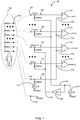
- FIG. 1 a schematic circuit diagram illustrating an impedance measurement apparatus 100 for determining impedance of a plurality of channels 104 , 106 and a patient impedance model 130 according to the preferred embodiment of the present invention is illustrated.
- the apparatus 100 can be utilized in biopotential measurements involving a plurality of electrodes 102 such as in electroencephalography (EEG), electromyography (EMG), electrocardiography (ECG), polysomnography (PSG) etc.
- EEG electroencephalography
- EMG electromyography
- ECG electrocardiography
- PSG polysomnography
- the apparatus 100 for determining impedance of a plurality of electrodes 102 comprises a plurality of channels 104 , 106 having a plurality of first channels 104 and a plurality of second channels 106 , at least one reference channel 108 , a signal generator 112 electrically connected to the plurality of channels 104 , 106 , a reference signal generator 114 connected to the reference channel 108 , at least one amplifier 110 connected to each of the plurality of channels 104 , 106 and the reference channel 108 and at least one filter arrangement 124 (see FIG. 2 ) connected to the output of the at least one amplifier 110 to filter the output signal from the at least one amplifier 110.
- the signal generator 112 is configured to provide a plurality of input signals 116 , 118 to the plurality of channels 104 , 106 .
- the plurality of first channels 104 may include 1 ... m channels and the plurality of second channels 106 may contain (m+1) ... n channels as illustrated in FIG. 1 .
- Each of the plurality of first channels 104 is connected to the positive terminal of the at least one amplifier 110 and supplied with a first input signal 116.
- Each of the plurality of second channels 106 is connected to the positive terminal of the at least on amplifier 110 and supplied with a second input signal 118.
- the signal generator 112 provides the first input signal 116 and the second input signal 118 such that the first input signal 116 is opposite the phase with the second input signal 118 . This is achieved by connecting an inverter 122 in parallel with the output of the signal generator 112 so that the first input signal 116 and the second input signal 118 are in opposite phase.
- a very low input potential for example, Vin(1) ...Vin(m) may be developed at the channels from 1 ...m and Vin(m+1) ... Vin(n) may be developed at the channels from m+1 ...n and Vref for the reference channel 108 .
- the at least one amplifier 110 can be a differential amplifier. The total noise generated at the electrode contact is generally significantly larger than expected thermal noise.
- the differential amplifier should have a common mode rejection factor sufficient to reduce unwanted differential output signals (as an equivalent differential input noise).
- the reference signal generator 114 is configured to provide an input signal 120 to the reference channel 108 such that the input signal 120 is orthogonal with respect to the first input signal 116 and the second input signal 118 .
- the input signal 120 is applied to the negative terminal of the at least one amplifier 110 through the reference channel 108.
- the reference channel 108 is configured as a reference potential for the plurality of channels 104 , 106.
- the plurality of channels 104, 106 , the reference 108 and the patient ground (GND) 132 are connected to the patient through a plurality of patient electrodes 134 .
- the first input signal 116, the second input signal 118 and the input signal 120 can be selected from a group consisting of: a sinusoidal alternating current, an oscillating electric potential and a periodically varying voltage with high internal resistance.
- the first input signal 116 , the second input signal 118 and the input signal 120 may be a symmetrical alternating current (AC) or a symmetrical direct current (DC). If it is not symmetrical, it at least has to be relatively symmetrical, such as DC levels centered around an arbitrary level instead of around a zero point or varying DC levels centered around an arbitrary level and not centered around a zero point.
- the corresponding amplified output voltages for example, can be V1...Vm and Vm+1 ... Vn.
- the first input signal 116, the second input signal 118 and the input signal 120 are applied to the plurality of channels 104, 106 and the reference channel 108 , the common mode voltage across the plurality of channels 104, 106 is minimized.
- the first input signal 116 is applied to the plurality of first channels 104 and the second input signal 118 opposite/inverse of the first input signal 116 is applied to the plurality of second channels 106 .
- the input signal 120 having a different frequency with respect to the first input signal 116 and second input signal 118 is applied to the reference channel 108 .
- the output from the at least one amplifier 110 contains an amplified signal from each of the plurality of channels 104, 106 and the reference channel 108 .
- the amplified signal contains mixed frequencies of signals from the at least one of the plurality of channels 104, 106 and the reference channel 108 .
- the output from the at least one amplifier 110 is given to a filter arrangement 124 as illustrated in FIG. 2 .
- the first input signal 116 is applied to the plurality of first channels 104 and the second input signal 118 opposite/inverse of the first input signal 116 is applied to the plurality of second channels 106 .
- the input signal 120 having a phase shift with respect to the first input signal 116 and second input signal 118, is applied to the reference channel 108 .
- the reference channel 108 is provided with the input signal 120 which has an orthogonal phase shift with respect to the first input signal 116 and the second input signal 118 .
- the output from the at least one amplifier 110 contains an amplified signal from each of the plurality of channels 104 , 106 and the reference channel 108 .
- the amplified signal after multiple cycles of cross correlation operation with the first input signal 116 gives the cross-correlated output signal corresponding to the first input signal 116 from which the impedance can be calculated. More information is illustrated in FIG. 3 and described in the associated text. Similarly, the impedance of each of the plurality of channels 104 , 106 can be calculated.
- FIG. 2 illustrates a block diagram of a filter arrangement 124 to determine the impedance of the plurality of channels 104, 106 according to the preferred embodiment of the present invention.
- the filter arrangement 124 includes a first filter 126 and a second filter 128 utilized to filter a signal having different frequencies.
- the first filter 126 and the second filter 128 can be a notch filter with different notch frequencies.
- the output from the at least one amplifier 110 is given to the filter arrangement 124.
- the first filter 126 may have a notch frequency the same as the input signal 120 given to the reference channel 108 thereby blocking the input signal frequency and providing an output signal having the frequency of the at least one of the plurality of channels 104, 106.
- the second filter 128 may have a notch frequency the same as the frequency of the at least one of the plurality of channels 104, 106 thereby blocking the frequency of the at least one of the plurality of channels 104, 106 and providing an output signal having the frequency of the input signal given to the reference channel 108 .
- the plurality of first channels 104 may include 1 ... m channels and the plurality of second channels 106 may contain (m+1) ... n channels.
- the output from the at least one amplifier 110 for the first channel is VI.
- the V1 is passed through the filter arrangement 124.
- the first filter 126 may have a notch frequency the same as the input signal 120 given to the reference channel 108 thereby blocking the reference frequency and providing an output signal Vch_1 having the frequency of the first input signal 116 of the first channel.
- the second filter 128 may have a notch frequency the same as the frequency of the first input signal 116 of the first channel thereby blocking the first input signal frequency and providing an output signal Vimp_1 having the frequency of the input signal 120 given to the reference channel 108 .
- Vn is the input to the filter arrangement 124, which gives an output Vch_n having the signal frequency of the n th channel and Vimp_n having the frequency of the input signal 120 of the reference channel 108 .
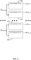
- FIG. 3 illustrates a block diagram of the output obtained after performing a cross correlation procedure to determine the impedance of the plurality of channels 104, 106 according to the preferred embodiment of the present invention.
- the first input signal 116 is applied to the plurality of first channels 104 and the second input signal 118 opposite of the first input signal 116 is applied to the plurality of second channels 106.
- the input signal 120 having a phase shift with respect to the first input signal 116 and second input signal 118, is applied to the reference channel 108.
- the reference channel 108 is provided with the input signal 120, which is orthogonal with respect to the first input signal 116 and the second input signal 118.
- the output from the at least one amplifier 110 contains an amplified signal from each of the plurality of channels 104, 106 and the reference channel 108 . After multiple cycles of cross correlation operation with the first input signal 116, the uncorrelated signal is removed from the reference signal and gives the cross correlated output signal for each of the plurality of first channels 104 from which the impedance can be calculated.
- the output signal V1 from the at least one amplifier 110 of the 1 st channel undergoes multiple cycles of cross correlation operation with the first input signal 116 and gives the cross correlated output signal Pch_1 as illustrated by block 300.
- the cross correlation operation of VI is performed with the input signal 120 of the reference channel 108 which gives the cross correlated output signal Pimp_1 as illustrated by block 302.
- Vn undergoes multiple cycles of cross correlation operation and gives outputs Pch_n and Pimp_n as illustrated by block 304 and 306 respectively.
- Sr[m]
- FIG. 4 illustrates a block diagram of a method for determining the impedance of the plurality of channels 104, 106 according to the preferred embodiment of the present invention.
- the simultaneous impedance testing method of a plurality of electrodes 102 comprises the steps of: providing an apparatus 100 for testing the impedance comprising a plurality of channels 104, 106 having a plurality of first channels 104 and a plurality of second channels 106, at least one reference channel 108, a signal generator 112 connected to the plurality of channels 104, 106 , a reference signal generator 108 connected to the reference channel 120, at least one amplifier 110 connected to each of the plurality of channels 104, 106 and the reference channel 108 and at least one filter 124 arrangement connected to an output of the at least one amplifier 110 to filter the signal from the at least one amplifier 110 as shown in block 400.
- the frequency of the input signal 120, the first input signal 116 and the second input signal 118 are different.
- the reference channel 108 is configured as a reference potential with respect to the plurality of channels 104, 106 .
- the input signal 120, the first input signal 116 and the second input signal 118 can be selected from a group consisting of: a sinusoidal alternating current, an oscillating electric potential and a periodically varying voltage with high internal resistance.
- the input signal 120, the first input signal 116 and the second input signal 118 minimize the common mode voltage across the plurality of channels 104, 106 and the reference channel 108.
- the impedance of the plurality of channels 104, 106 is determined by applying the first input signal 116 to the plurality of first channels 104 and simultaneously applying the second input signal 118 inverse of the first input signal 116 to the plurality of second channels 106 . Simultaneously determining the impedance of the reference channel 108 by applying the input signal 120 to the reference channel 108 such that the input signal 120 has an orthogonal phase shift with respect to the first input signal 116 and the second input signal 118 .
- the impedance of the plurality of channels 104, 106 is determined by applying the input signal 120 to the reference channel 108 from the reference signal generator 114. Then, applying the first input signal 116 to the plurality of first channels 104 and simultaneously applying the second input signal 118 to the plurality of second channels 106 such that the second input signal 118 has an opposite phase with respect to the first input signal 116 .
- the impedance of the reference channel 108 and the plurality of first channels 104 and the plurality of second channels 106 are determined from the cross correlation function.
- the impedance is determined by simultaneously applying a plurality of input signals 116, 118 to the plurality of channels 104, 106 such that the common mode voltage of the plurality of channels 104, 106 with respect to the reference channel 108 is minimized. Simultaneously, applying an input signal 120 to the reference channel 108 such that the input signal 120 has a different frequency with respect to the plurality of input signals 116, 118 . Then, determining the impedance of the plurality of channels 104, 106 and the reference channel 108 by measuring the output from the at least one filter arrangement 124 connected therewith.
- the impedance is determined by simultaneously applying a plurality of input signals 116, 118 to the plurality of channels 104, 106 such that the common mode voltage of the plurality of channels 104, 106 with respect to the reference channel 108 is minimized. Simultaneously, applying an input signal 120 to the reference channel 108 such that the input signal 120 has a phase shift relative to the plurality of input signals 116, 118. Then, determining the impedance of the plurality of channels 104, 106 and the reference channel 108 by measuring the output after multiple cycles of cross correlation.
- the impedance is determined by applying an input signal 120 from the reference signal generator 114 to the reference channel 108. Then, by applying the first input signal 116 to the plurality of first channels 104 and simultaneously applying the second input signal 118 to the plurality of second channels 106 such that second input signal 118 has a phase opposite of the first input signal 116 and the frequency of the second input signal 118 is different from the frequency of the first input signal 116.
- the impedance of the reference channel 108, the plurality of first channels 104 and the plurality of second channels 106 can be determined.
- FIG. 5 is a schematic circuit diagram illustrating an impedance measurement apparatus 200 for determining impedance of a plurality of channels 204, 206 according to one embodiment of the present invention.
- the apparatus 200 for determining impedance of a plurality of electrodes 202 comprises a plurality of channels 204, 206 having a plurality of first channels 204 and a plurality of second channels 206, at least one reference channel 208, a signal generator 212 electrically connected to the plurality of channels 204, 206 and the reference channel 208 by means of a switching arrangement 214, at least one amplifier 210 connected to each of the plurality of channels 204, 206 and the reference channel 208 and at least one filter 124 (see FIG.
- the plurality of electrodes 202 is attached to the plurality of patient electrodes 234 as illustrated by the patient impedance model 230 .
- the signal generator 212 is configured to provide a plurality of input signals 216, 218 and 220 to the plurality of channels 204, 206 and the reference channel 208 by means of the switching arrangement 214 .
- the switching arrangement 214 is a single pole double throw switch.
- the switching arrangement 214 has a first contact point 236 and a second contact point 238 as illustrated in FIG. 5 .
- the plurality of first channels 204 may include from 1 to m channels and the plurality of second channels may contain (m+1) to n channels.
- Each of the plurality of first channels 204 and each of the plurality of second channels 206 is connected to the positive terminal of the at least one amplifier 210.
- the signal generator 210 When the switching arrangement 214 is at the first contact point 236, the signal generator 210 provides a first input signal 216 to the plurality of first channels 204 and a second input signal 218 to the plurality of second channels 206 such that the first input signal 216 is opposite the phase with the second input signal 218. This is achieved by connecting an inverter 222 connected in parallel after the first contact point 236 so that the first input signal 216 and the second input signal 218 are in opposite phase.
- the at least one amplifier 210 may be a differential amplifier comprising a common mode rejection factor sufficient to reduce unwanted differential output signals (as an equivalent differential input noise).
- the input signal 220 is provided to the reference channel 208 such that the input signal 220 has a different frequency with respect to the first input signal 216 and the second input signal 218 .
- the input signal 220 may be applied to the negative terminal of the at least one amplifier 210 connected through the reference channel 208.
- the reference channel 208 is configured as a reference potential for the plurality of channels 204, 206.
- the plurality of channels 204, 206 , the reference 208 and the patient ground (GND) 232 are connected to the patient through the plurality of patient electrodes 234.
- the first input signal 216, the second input signal 218 and the input signal 220 may be selected from the group consisting of: a sinusoidal alternating current, an oscillating electric potential and a periodically varying voltage with high internal resistance.
- the first input signal 216, the second input signal 218 and the input signal 220 may be a symmetrical alternating current (AC) or a symmetrical direct current (DC). If it is not symmetrical, it at least has to be the relatively symmetrical, such as DC levels centered around an arbitrary level instead of around a zero point or varying DC levels centered around an arbitrary level and not centered around a zero point.
- the impedance of the plurality of channels 204, 206 is determined by applying the plurality of input signals 216, 218 to the plurality of channels 204, 206 such that the common mode voltage of the plurality of channels 204, 206 with respect to the reference channel 208 is minimized.
- the impedance of the reference channel 208 is determined by applying an input signal 220 to the reference channel 208 .
- the switching arrangement 214 is positioned at the first contact point 236. Then, by applying the plurality of input signals 216 , 218 to the plurality of channels 204 , 206 and measuring the amplified signal from the at least one amplifier 210 connected to each of the plurality of channels 204, 206. And calculating the impedance for each of the plurality of channels 204, 206. To determine the impedance of the reference channel 208, the switching arrangement 214 is positioned at the second contact point 238. Then, by applying the input signal 220 to the reference channel 208 and measuring the amplified signal from the at least one amplifier 210 connected to each of the plurality of channels 204, 206 .
- the amplified signal from each of the plurality of channels 204, 206 contains either signals from the reference channel 108 or signal from each of the plurality of channels 204, 206 depending on the switching arrangement 214 positions.
- the impedances can be calculated through the following formula:
Applications Claiming Priority (3)
| Application Number | Priority Date | Filing Date | Title |
|---|---|---|---|
| US14/521,382 US9594104B2 (en) | 2014-10-22 | 2014-10-22 | Simultaneous impedance testing method and apparatus |
| PCT/US2015/042144 WO2016064456A1 (en) | 2014-10-22 | 2015-07-25 | Simultaneous impedance testing method and apparatus |
| EP15851703.7A EP3209197B1 (de) | 2014-10-22 | 2015-07-25 | Verfahren und vorrichtung zur simultanen impedanzprüfung |
Related Parent Applications (2)
| Application Number | Title | Priority Date | Filing Date |
|---|---|---|---|
| EP15851703.7A Division EP3209197B1 (de) | 2014-10-22 | 2015-07-25 | Verfahren und vorrichtung zur simultanen impedanzprüfung |
| EP15851703.7A Division-Into EP3209197B1 (de) | 2014-10-22 | 2015-07-25 | Verfahren und vorrichtung zur simultanen impedanzprüfung |
Publications (2)
| Publication Number | Publication Date |
|---|---|
| EP3330724A1 true EP3330724A1 (de) | 2018-06-06 |
| EP3330724B1 EP3330724B1 (de) | 2022-11-16 |
Family
ID=55761292
Family Applications (2)
| Application Number | Title | Priority Date | Filing Date |
|---|---|---|---|
| EP17199360.3A Active EP3330724B1 (de) | 2014-10-22 | 2015-07-25 | Verfahren und vorrichtung zur simultanen impedanzprüfung |
| EP15851703.7A Active EP3209197B1 (de) | 2014-10-22 | 2015-07-25 | Verfahren und vorrichtung zur simultanen impedanzprüfung |
Family Applications After (1)
| Application Number | Title | Priority Date | Filing Date |
|---|---|---|---|
| EP15851703.7A Active EP3209197B1 (de) | 2014-10-22 | 2015-07-25 | Verfahren und vorrichtung zur simultanen impedanzprüfung |
Country Status (5)
| Country | Link |
|---|---|
| US (1) | US9594104B2 (de) |
| EP (2) | EP3330724B1 (de) |
| CN (1) | CN106572800B (de) |
| DK (2) | DK3209197T3 (de) |
| WO (1) | WO2016064456A1 (de) |
Cited By (1)
| Publication number | Priority date | Publication date | Assignee | Title |
|---|---|---|---|---|
| WO2024047076A1 (en) * | 2022-08-30 | 2024-03-07 | Kite Medical Limited | System and method for measuring common-mode signal |
Families Citing this family (6)
| Publication number | Priority date | Publication date | Assignee | Title |
|---|---|---|---|---|
| US10799161B2 (en) * | 2016-04-04 | 2020-10-13 | Technische Universität Berlin | Biosignal acquisition device and system, method for acquisition of biosignals |
| JP7011730B2 (ja) * | 2017-12-04 | 2022-01-27 | エアロジェット ロケットダイン インコーポレイテッド | 負荷インピーダンステスターおよび測定方法 |
| US10874318B2 (en) * | 2018-03-06 | 2020-12-29 | Cardioinsight Technologies, Inc. | Channel integrity detection and reconstruction of electrophysiological signals |
| CN110811618B (zh) * | 2019-11-24 | 2023-09-12 | 西北机器有限公司 | 一种电阻抗断层成像数据采集系统及方法 |
| CN110974210B (zh) * | 2019-12-09 | 2022-05-20 | 武汉联影智融医疗科技有限公司 | 生理信号采集通路阻抗校正方法及装置 |
| CN113504438B (zh) * | 2021-06-08 | 2023-11-28 | 漳州科华电气技术有限公司 | 用于列头柜绝缘阻抗检测的方法、装置及列头柜 |
Citations (8)
| Publication number | Priority date | Publication date | Assignee | Title |
|---|---|---|---|---|
| US4409987A (en) * | 1978-06-09 | 1983-10-18 | Beckman Instruments, Inc. | Electroencephalograph |
| US5020541A (en) * | 1988-07-13 | 1991-06-04 | Physio-Control Corporation | Apparatus for sensing lead and transthoracic impedances |
| EP0800787A1 (de) * | 1996-04-12 | 1997-10-15 | Siemens-Elema AB | Vorrichtung zur Überwachung von Messelektroden, zum Erfassen von physiologischen Signalen, und deren Leitern |
| US20060020218A1 (en) * | 2004-02-26 | 2006-01-26 | Warwick Freeman | Method and apparatus for continuous electrode impedance monitoring |
| US20070038257A1 (en) * | 2005-08-11 | 2007-02-15 | Gray James M | Impedance measurement apparatus for assessment of biomedical electrode interface quality |
| US20090043221A1 (en) * | 2007-08-10 | 2009-02-12 | Consolidated Research, Inc. | Apparatus and method for high-speed determination of bioelectric electrode impedances |
| EP2294979A1 (de) * | 2009-09-14 | 2011-03-16 | Imec | Verfahren und elektronisches medizinisches Gerät für simultane Messung sowie Impedanz und Biopotenzialsignal |
| US8086300B2 (en) * | 2006-11-10 | 2011-12-27 | Koninklijke Philips Electronics N.V. | ECG electrode contact quality measurement system |
Family Cites Families (22)
| Publication number | Priority date | Publication date | Assignee | Title |
|---|---|---|---|---|
| DE19755418A1 (de) | 1997-12-12 | 1999-06-24 | Fraunhofer Ges Forschung | Sensorelement und Vorrichtung zur Messung komplexer Impedanzen sowie Verwendung der Vorrichtung |
| TW436276B (en) | 1999-06-30 | 2001-05-28 | Ind Tech Res Inst | Device for detecting leads-off condition in a multi-electrode medical diagnosis system and method thereof |
| US6525522B1 (en) | 2001-06-07 | 2003-02-25 | Tektronix, Inc. | System for determining the phase and magnitude of an incident signal relative to a cyclical reference signal |
| US6625487B2 (en) | 2001-07-17 | 2003-09-23 | Koninklijke Philips Electronics N.V. | Bioelectrical impedance ECG measurement and defibrillator implementing same |
| WO2004075738A2 (en) | 2003-02-26 | 2004-09-10 | Compumedics Usa, Inc. | Method and apparatus for continuous electrode impedance monitoring |
| JP3833199B2 (ja) * | 2003-07-24 | 2006-10-11 | 沖電気工業株式会社 | 相補信号発生回路 |
| JP2005080720A (ja) | 2003-09-05 | 2005-03-31 | Tanita Corp | 生体電気インピーダンス測定装置 |
| US8150643B1 (en) | 2004-12-21 | 2012-04-03 | Battelle Energy Alliance, Llc | Method of detecting system function by measuring frequency response |
| GB2433326B (en) | 2005-12-16 | 2009-10-28 | Orrcam Ltd | Measuring electrical impedance at various frequencies |
| WO2007121756A2 (en) | 2006-04-24 | 2007-11-01 | Oü Eliko Tehnoloogia Arenduskeskus | Method and device for multichannel multifrequency analysis of an object |
| WO2008063195A1 (en) | 2006-10-12 | 2008-05-29 | St. Jude Medical, Atrial Fibrillation Division, Inc. | Assessment of electrode coupling for tissue ablation |
| FR2908973A1 (fr) | 2006-11-24 | 2008-05-30 | Yves Faisandier | Dispositif d'enregistrement de signaux electriques physiologiques associant les donnees et les valeurs d'impedance des lignes d'entree dans le flux enregistre |
| US9788750B2 (en) | 2007-04-30 | 2017-10-17 | Medtronic, Inc. | Seizure prediction |
| WO2009023334A2 (en) | 2007-05-18 | 2009-02-19 | University Of Southern California | Biomimetic tactile sensor for control of grip |
| CN101951832B (zh) * | 2007-06-22 | 2013-06-12 | Cmte开发有限公司 | 头皮电势测量方法和设备 |
| US8738139B2 (en) | 2007-08-01 | 2014-05-27 | Bruce Lanning | Wireless system for epilepsy monitoring and measurement |
| KR101007558B1 (ko) | 2008-10-08 | 2011-01-14 | 한국과학기술연구원 | 실험용 동물 eeg 측정용 박막형 다채널 미세전극 및 미세전극을 이용한 실험용 동물 eeg 측정 방법 |
| EE01061U1 (et) * | 2009-02-12 | 2012-01-16 | JR Medical O� | Mitmekanaliline impedantskardiograaf |
| IT1394636B1 (it) * | 2009-06-23 | 2012-07-05 | St Microelectronics Rousset | Circuito di generazione di un segnale di riferimento per un convertitore a/d di un trasduttore acustico microelettromeccanico e relativo metodo |
| KR101123539B1 (ko) | 2010-07-09 | 2012-03-16 | 한국해양대학교 산학협력단 | 접지임피던스의 고정도 측정장치 |
| NL2008441C2 (en) * | 2012-03-09 | 2013-09-10 | Twente Medical Systems Internat B V | Apparatus for processing signals. |
| US9113805B2 (en) | 2013-03-04 | 2015-08-25 | Mortara Instrument, Inc. | Impedance measurement system |
-
2014
- 2014-10-22 US US14/521,382 patent/US9594104B2/en active Active
-
2015
- 2015-07-25 EP EP17199360.3A patent/EP3330724B1/de active Active
- 2015-07-25 DK DK15851703.7T patent/DK3209197T3/da active
- 2015-07-25 WO PCT/US2015/042144 patent/WO2016064456A1/en active Application Filing
- 2015-07-25 EP EP15851703.7A patent/EP3209197B1/de active Active
- 2015-07-25 CN CN201580042332.9A patent/CN106572800B/zh active Active
- 2015-07-25 DK DK17199360.3T patent/DK3330724T3/da active
Patent Citations (8)
| Publication number | Priority date | Publication date | Assignee | Title |
|---|---|---|---|---|
| US4409987A (en) * | 1978-06-09 | 1983-10-18 | Beckman Instruments, Inc. | Electroencephalograph |
| US5020541A (en) * | 1988-07-13 | 1991-06-04 | Physio-Control Corporation | Apparatus for sensing lead and transthoracic impedances |
| EP0800787A1 (de) * | 1996-04-12 | 1997-10-15 | Siemens-Elema AB | Vorrichtung zur Überwachung von Messelektroden, zum Erfassen von physiologischen Signalen, und deren Leitern |
| US20060020218A1 (en) * | 2004-02-26 | 2006-01-26 | Warwick Freeman | Method and apparatus for continuous electrode impedance monitoring |
| US20070038257A1 (en) * | 2005-08-11 | 2007-02-15 | Gray James M | Impedance measurement apparatus for assessment of biomedical electrode interface quality |
| US8086300B2 (en) * | 2006-11-10 | 2011-12-27 | Koninklijke Philips Electronics N.V. | ECG electrode contact quality measurement system |
| US20090043221A1 (en) * | 2007-08-10 | 2009-02-12 | Consolidated Research, Inc. | Apparatus and method for high-speed determination of bioelectric electrode impedances |
| EP2294979A1 (de) * | 2009-09-14 | 2011-03-16 | Imec | Verfahren und elektronisches medizinisches Gerät für simultane Messung sowie Impedanz und Biopotenzialsignal |
Cited By (1)
| Publication number | Priority date | Publication date | Assignee | Title |
|---|---|---|---|---|
| WO2024047076A1 (en) * | 2022-08-30 | 2024-03-07 | Kite Medical Limited | System and method for measuring common-mode signal |
Also Published As
| Publication number | Publication date |
|---|---|
| CN106572800B (zh) | 2020-07-14 |
| EP3330724B1 (de) | 2022-11-16 |
| EP3209197A1 (de) | 2017-08-30 |
| US9594104B2 (en) | 2017-03-14 |
| DK3209197T3 (da) | 2022-03-21 |
| EP3209197B1 (de) | 2022-01-26 |
| CN106572800A (zh) | 2017-04-19 |
| WO2016064456A1 (en) | 2016-04-28 |
| US20160116516A1 (en) | 2016-04-28 |
| DK3330724T3 (da) | 2023-01-23 |
| EP3209197A4 (de) | 2018-06-13 |
Similar Documents
| Publication | Publication Date | Title |
|---|---|---|
| EP3209197B1 (de) | Verfahren und vorrichtung zur simultanen impedanzprüfung | |
| US8089283B2 (en) | Apparatus and method for high-speed determination of bioelectric electrode impedances | |
| US20150241505A1 (en) | System And Method For Measuring Contact Impedance Of An Electrode | |
| JP6234795B2 (ja) | マルチチャンネルecg測定 | |
| US9291654B2 (en) | Patient electrode impedance measurement | |
| EP2896360B1 (de) | Vorrichtung und Verfahren zur Messung der Bioimpedanz | |
| Ibrahim et al. | Bio-impedance spectroscopy (BIS) measurement system for wearable devices | |
| IL275215B2 (en) | Expanding ECG acquisition capabilities in a catheter-based cardiac system | |
| Assambo et al. | Determination of the parameters of the skin-electrode impedance model for ECG measurement | |
| US20130338529A1 (en) | Bioelectric signal measurement apparatus | |
| US20170020405A1 (en) | Ecg electrode and leadwire connection integrity detection | |
| RU2732344C2 (ru) | Система, регистратор и способ поверхностной электромиографии | |
| Spinelli et al. | A practical approach to electrode-skin impedance unbalance measurement | |
| Saadi et al. | Electrode-gel-skin interface characterization and modeling for surface biopotential recording: Impedance measurements and noise | |
| WO2014051590A1 (en) | System and method for detecting a status of electrodes of a patient monitoring device | |
| CN108055823A (zh) | 流体水平确定 | |
| Gracia et al. | Multilead measurement system for the time-domain analysis of bioimpedance magnitude | |
| Vargas Luna et al. | Comparison of twitch responses during current‐or voltage‐controlled transcutaneous neuromuscular electrical stimulation | |
| Crandall et al. | Characterization of the Analog Device Inc (ADI) MAX30009 Bioimpedance Analog Front End Chip | |
| Patel et al. | Evaluating ECG capturing using sound-card of PC/laptop | |
| Kadir et al. | A multi-frequency focused impedance measurement system based on analogue synchronous peak detection | |
| Birok et al. | Design of Low Cost Bio-impedance Measuring Instrument | |
| Marszałek et al. | Investigations of real conditions properties of the biomedical electrodes with integrated electrode contact quality monitoring system for recording electrocardiographic signals | |
| Uiniversity | BIOMEDICAL INSTRUMENTATION | |
| Pandey | An Embedded Design Example: A Thorax Simulator for Testing and Calibration of Impedance Cardiographs |
Legal Events
| Date | Code | Title | Description |
|---|---|---|---|
| PUAI | Public reference made under article 153(3) epc to a published international application that has entered the european phase |
Free format text: ORIGINAL CODE: 0009012 |
|
| STAA | Information on the status of an ep patent application or granted ep patent |
Free format text: STATUS: THE APPLICATION HAS BEEN PUBLISHED |
|
| AC | Divisional application: reference to earlier application |
Ref document number: 3209197 Country of ref document: EP Kind code of ref document: P |
|
| AK | Designated contracting states |
Kind code of ref document: A1 Designated state(s): AL AT BE BG CH CY CZ DE DK EE ES FI FR GB GR HR HU IE IS IT LI LT LU LV MC MK MT NL NO PL PT RO RS SE SI SK SM TR |
|
| AX | Request for extension of the european patent |
Extension state: BA ME |
|
| STAA | Information on the status of an ep patent application or granted ep patent |
Free format text: STATUS: REQUEST FOR EXAMINATION WAS MADE |
|
| 17P | Request for examination filed |
Effective date: 20181205 |
|
| RBV | Designated contracting states (corrected) |
Designated state(s): AL AT BE BG CH CY CZ DE DK EE ES FI FR GB GR HR HU IE IS IT LI LT LU LV MC MK MT NL NO PL PT RO RS SE SI SK SM TR |
|
| STAA | Information on the status of an ep patent application or granted ep patent |
Free format text: STATUS: REQUEST FOR EXAMINATION WAS MADE |
|
| GRAP | Despatch of communication of intention to grant a patent |
Free format text: ORIGINAL CODE: EPIDOSNIGR1 |
|
| STAA | Information on the status of an ep patent application or granted ep patent |
Free format text: STATUS: GRANT OF PATENT IS INTENDED |
|
| RIC1 | Information provided on ipc code assigned before grant |
Ipc: A61B 5/369 20210101ALI20211203BHEP Ipc: G01R 27/00 20060101ALI20211203BHEP Ipc: G01R 27/02 20060101ALI20211203BHEP Ipc: A61B 5/304 20210101ALI20211203BHEP Ipc: G01R 27/28 20060101AFI20211203BHEP |
|
| INTG | Intention to grant announced |
Effective date: 20211220 |
|
| GRAJ | Information related to disapproval of communication of intention to grant by the applicant or resumption of examination proceedings by the epo deleted |
Free format text: ORIGINAL CODE: EPIDOSDIGR1 |
|
| STAA | Information on the status of an ep patent application or granted ep patent |
Free format text: STATUS: REQUEST FOR EXAMINATION WAS MADE |
|
| INTC | Intention to grant announced (deleted) | ||
| GRAP | Despatch of communication of intention to grant a patent |
Free format text: ORIGINAL CODE: EPIDOSNIGR1 |
|
| STAA | Information on the status of an ep patent application or granted ep patent |
Free format text: STATUS: GRANT OF PATENT IS INTENDED |
|
| INTG | Intention to grant announced |
Effective date: 20220613 |
|
| GRAS | Grant fee paid |
Free format text: ORIGINAL CODE: EPIDOSNIGR3 |
|
| GRAA | (expected) grant |
Free format text: ORIGINAL CODE: 0009210 |
|
| STAA | Information on the status of an ep patent application or granted ep patent |
Free format text: STATUS: THE PATENT HAS BEEN GRANTED |
|
| AC | Divisional application: reference to earlier application |
Ref document number: 3209197 Country of ref document: EP Kind code of ref document: P |
|
| AK | Designated contracting states |
Kind code of ref document: B1 Designated state(s): AL AT BE BG CH CY CZ DE DK EE ES FI FR GB GR HR HU IE IS IT LI LT LU LV MC MK MT NL NO PL PT RO RS SE SI SK SM TR |
|
| REG | Reference to a national code |
Ref country code: GB Ref legal event code: FG4D |
|
| REG | Reference to a national code |
Ref country code: CH Ref legal event code: EP |
|
| REG | Reference to a national code |
Ref country code: DE Ref legal event code: R096 Ref document number: 602015081642 Country of ref document: DE |
|
| REG | Reference to a national code |
Ref country code: IE Ref legal event code: FG4D |
|
| REG | Reference to a national code |
Ref country code: AT Ref legal event code: REF Ref document number: 1532071 Country of ref document: AT Kind code of ref document: T Effective date: 20221215 |
|
| REG | Reference to a national code |
Ref country code: DK Ref legal event code: T3 Effective date: 20230118 |
|
| REG | Reference to a national code |
Ref country code: LT Ref legal event code: MG9D |
|
| REG | Reference to a national code |
Ref country code: NL Ref legal event code: MP Effective date: 20221116 |
|
| REG | Reference to a national code |
Ref country code: AT Ref legal event code: MK05 Ref document number: 1532071 Country of ref document: AT Kind code of ref document: T Effective date: 20221116 |
|
| PG25 | Lapsed in a contracting state [announced via postgrant information from national office to epo] |
Ref country code: SE Free format text: LAPSE BECAUSE OF FAILURE TO SUBMIT A TRANSLATION OF THE DESCRIPTION OR TO PAY THE FEE WITHIN THE PRESCRIBED TIME-LIMIT Effective date: 20221116 Ref country code: PT Free format text: LAPSE BECAUSE OF FAILURE TO SUBMIT A TRANSLATION OF THE DESCRIPTION OR TO PAY THE FEE WITHIN THE PRESCRIBED TIME-LIMIT Effective date: 20230316 Ref country code: NO Free format text: LAPSE BECAUSE OF FAILURE TO SUBMIT A TRANSLATION OF THE DESCRIPTION OR TO PAY THE FEE WITHIN THE PRESCRIBED TIME-LIMIT Effective date: 20230216 Ref country code: LT Free format text: LAPSE BECAUSE OF FAILURE TO SUBMIT A TRANSLATION OF THE DESCRIPTION OR TO PAY THE FEE WITHIN THE PRESCRIBED TIME-LIMIT Effective date: 20221116 Ref country code: FI Free format text: LAPSE BECAUSE OF FAILURE TO SUBMIT A TRANSLATION OF THE DESCRIPTION OR TO PAY THE FEE WITHIN THE PRESCRIBED TIME-LIMIT Effective date: 20221116 Ref country code: ES Free format text: LAPSE BECAUSE OF FAILURE TO SUBMIT A TRANSLATION OF THE DESCRIPTION OR TO PAY THE FEE WITHIN THE PRESCRIBED TIME-LIMIT Effective date: 20221116 Ref country code: AT Free format text: LAPSE BECAUSE OF FAILURE TO SUBMIT A TRANSLATION OF THE DESCRIPTION OR TO PAY THE FEE WITHIN THE PRESCRIBED TIME-LIMIT Effective date: 20221116 |
|
| PG25 | Lapsed in a contracting state [announced via postgrant information from national office to epo] |
Ref country code: RS Free format text: LAPSE BECAUSE OF FAILURE TO SUBMIT A TRANSLATION OF THE DESCRIPTION OR TO PAY THE FEE WITHIN THE PRESCRIBED TIME-LIMIT Effective date: 20221116 Ref country code: PL Free format text: LAPSE BECAUSE OF FAILURE TO SUBMIT A TRANSLATION OF THE DESCRIPTION OR TO PAY THE FEE WITHIN THE PRESCRIBED TIME-LIMIT Effective date: 20221116 Ref country code: LV Free format text: LAPSE BECAUSE OF FAILURE TO SUBMIT A TRANSLATION OF THE DESCRIPTION OR TO PAY THE FEE WITHIN THE PRESCRIBED TIME-LIMIT Effective date: 20221116 Ref country code: IS Free format text: LAPSE BECAUSE OF FAILURE TO SUBMIT A TRANSLATION OF THE DESCRIPTION OR TO PAY THE FEE WITHIN THE PRESCRIBED TIME-LIMIT Effective date: 20230316 Ref country code: HR Free format text: LAPSE BECAUSE OF FAILURE TO SUBMIT A TRANSLATION OF THE DESCRIPTION OR TO PAY THE FEE WITHIN THE PRESCRIBED TIME-LIMIT Effective date: 20221116 Ref country code: GR Free format text: LAPSE BECAUSE OF FAILURE TO SUBMIT A TRANSLATION OF THE DESCRIPTION OR TO PAY THE FEE WITHIN THE PRESCRIBED TIME-LIMIT Effective date: 20230217 |
|
| P01 | Opt-out of the competence of the unified patent court (upc) registered |
Effective date: 20230507 |
|
| PG25 | Lapsed in a contracting state [announced via postgrant information from national office to epo] |
Ref country code: NL Free format text: LAPSE BECAUSE OF FAILURE TO SUBMIT A TRANSLATION OF THE DESCRIPTION OR TO PAY THE FEE WITHIN THE PRESCRIBED TIME-LIMIT Effective date: 20221116 |
|
| PG25 | Lapsed in a contracting state [announced via postgrant information from national office to epo] |
Ref country code: SM Free format text: LAPSE BECAUSE OF FAILURE TO SUBMIT A TRANSLATION OF THE DESCRIPTION OR TO PAY THE FEE WITHIN THE PRESCRIBED TIME-LIMIT Effective date: 20221116 Ref country code: RO Free format text: LAPSE BECAUSE OF FAILURE TO SUBMIT A TRANSLATION OF THE DESCRIPTION OR TO PAY THE FEE WITHIN THE PRESCRIBED TIME-LIMIT Effective date: 20221116 Ref country code: EE Free format text: LAPSE BECAUSE OF FAILURE TO SUBMIT A TRANSLATION OF THE DESCRIPTION OR TO PAY THE FEE WITHIN THE PRESCRIBED TIME-LIMIT Effective date: 20221116 Ref country code: CZ Free format text: LAPSE BECAUSE OF FAILURE TO SUBMIT A TRANSLATION OF THE DESCRIPTION OR TO PAY THE FEE WITHIN THE PRESCRIBED TIME-LIMIT Effective date: 20221116 |
|
| REG | Reference to a national code |
Ref country code: DE Ref legal event code: R097 Ref document number: 602015081642 Country of ref document: DE |
|
| PG25 | Lapsed in a contracting state [announced via postgrant information from national office to epo] |
Ref country code: SK Free format text: LAPSE BECAUSE OF FAILURE TO SUBMIT A TRANSLATION OF THE DESCRIPTION OR TO PAY THE FEE WITHIN THE PRESCRIBED TIME-LIMIT Effective date: 20221116 Ref country code: AL Free format text: LAPSE BECAUSE OF FAILURE TO SUBMIT A TRANSLATION OF THE DESCRIPTION OR TO PAY THE FEE WITHIN THE PRESCRIBED TIME-LIMIT Effective date: 20221116 |
|
| PLBE | No opposition filed within time limit |
Free format text: ORIGINAL CODE: 0009261 |
|
| STAA | Information on the status of an ep patent application or granted ep patent |
Free format text: STATUS: NO OPPOSITION FILED WITHIN TIME LIMIT |
|
| 26N | No opposition filed |
Effective date: 20230817 |
|
| PGFP | Annual fee paid to national office [announced via postgrant information from national office to epo] |
Ref country code: GB Payment date: 20230824 Year of fee payment: 9 |
|
| PG25 | Lapsed in a contracting state [announced via postgrant information from national office to epo] |
Ref country code: SI Free format text: LAPSE BECAUSE OF FAILURE TO SUBMIT A TRANSLATION OF THE DESCRIPTION OR TO PAY THE FEE WITHIN THE PRESCRIBED TIME-LIMIT Effective date: 20221116 |
|
| PGFP | Annual fee paid to national office [announced via postgrant information from national office to epo] |
Ref country code: FR Payment date: 20230824 Year of fee payment: 10 Ref country code: DK Payment date: 20230926 Year of fee payment: 9 Ref country code: DE Payment date: 20230929 Year of fee payment: 9 |
|
| PG25 | Lapsed in a contracting state [announced via postgrant information from national office to epo] |
Ref country code: MC Free format text: LAPSE BECAUSE OF FAILURE TO SUBMIT A TRANSLATION OF THE DESCRIPTION OR TO PAY THE FEE WITHIN THE PRESCRIBED TIME-LIMIT Effective date: 20221116 |
|
| PG25 | Lapsed in a contracting state [announced via postgrant information from national office to epo] |
Ref country code: MC Free format text: LAPSE BECAUSE OF FAILURE TO SUBMIT A TRANSLATION OF THE DESCRIPTION OR TO PAY THE FEE WITHIN THE PRESCRIBED TIME-LIMIT Effective date: 20221116 |
|
| REG | Reference to a national code |
Ref country code: CH Ref legal event code: PL |
|
| REG | Reference to a national code |
Ref country code: BE Ref legal event code: MM Effective date: 20230731 |
|
| PG25 | Lapsed in a contracting state [announced via postgrant information from national office to epo] |
Ref country code: LU Free format text: LAPSE BECAUSE OF NON-PAYMENT OF DUE FEES Effective date: 20230725 |
|
| PG25 | Lapsed in a contracting state [announced via postgrant information from national office to epo] |
Ref country code: LU Free format text: LAPSE BECAUSE OF NON-PAYMENT OF DUE FEES Effective date: 20230725 |
|
| PG25 | Lapsed in a contracting state [announced via postgrant information from national office to epo] |
Ref country code: CH Free format text: LAPSE BECAUSE OF NON-PAYMENT OF DUE FEES Effective date: 20230731 |