EP3330665A2 - Dual-vibratory pattern resonator gyroscope - Google Patents
Dual-vibratory pattern resonator gyroscope Download PDFInfo
- Publication number
- EP3330665A2 EP3330665A2 EP17202551.2A EP17202551A EP3330665A2 EP 3330665 A2 EP3330665 A2 EP 3330665A2 EP 17202551 A EP17202551 A EP 17202551A EP 3330665 A2 EP3330665 A2 EP 3330665A2
- Authority
- EP
- European Patent Office
- Prior art keywords
- resonator
- vibration pattern
- gyroscope
- resonator gyroscope
- rotation
- Prior art date
- Legal status (The legal status is an assumption and is not a legal conclusion. Google has not performed a legal analysis and makes no representation as to the accuracy of the status listed.)
- Granted
Links
- 230000000737 periodic effect Effects 0.000 claims abstract description 32
- 238000005259 measurement Methods 0.000 claims description 30
- 238000000034 method Methods 0.000 claims description 22
- 238000010586 diagram Methods 0.000 description 4
- 238000006073 displacement reaction Methods 0.000 description 3
- 230000000694 effects Effects 0.000 description 2
- 230000010354 integration Effects 0.000 description 2
- SGTNSNPWRIOYBX-UHFFFAOYSA-N 2-(3,4-dimethoxyphenyl)-5-{[2-(3,4-dimethoxyphenyl)ethyl](methyl)amino}-2-(propan-2-yl)pentanenitrile Chemical compound C1=C(OC)C(OC)=CC=C1CCN(C)CCCC(C#N)(C(C)C)C1=CC=C(OC)C(OC)=C1 SGTNSNPWRIOYBX-UHFFFAOYSA-N 0.000 description 1
- 230000004075 alteration Effects 0.000 description 1
- 230000009977 dual effect Effects 0.000 description 1
- 239000011521 glass Substances 0.000 description 1
- 238000002347 injection Methods 0.000 description 1
- 239000007924 injection Substances 0.000 description 1
- 239000000463 material Substances 0.000 description 1
- 238000012986 modification Methods 0.000 description 1
- 230000004048 modification Effects 0.000 description 1
- 238000007619 statistical method Methods 0.000 description 1
Images


Classifications
-
- G—PHYSICS
- G01—MEASURING; TESTING
- G01C—MEASURING DISTANCES, LEVELS OR BEARINGS; SURVEYING; NAVIGATION; GYROSCOPIC INSTRUMENTS; PHOTOGRAMMETRY OR VIDEOGRAMMETRY
- G01C19/00—Gyroscopes; Turn-sensitive devices using vibrating masses; Turn-sensitive devices without moving masses; Measuring angular rate using gyroscopic effects
- G01C19/56—Turn-sensitive devices using vibrating masses, e.g. vibratory angular rate sensors based on Coriolis forces
- G01C19/567—Turn-sensitive devices using vibrating masses, e.g. vibratory angular rate sensors based on Coriolis forces using the phase shift of a vibration node or antinode
- G01C19/5677—Turn-sensitive devices using vibrating masses, e.g. vibratory angular rate sensors based on Coriolis forces using the phase shift of a vibration node or antinode of essentially two-dimensional vibrators, e.g. ring-shaped vibrators
-
- G—PHYSICS
- G01—MEASURING; TESTING
- G01C—MEASURING DISTANCES, LEVELS OR BEARINGS; SURVEYING; NAVIGATION; GYROSCOPIC INSTRUMENTS; PHOTOGRAMMETRY OR VIDEOGRAMMETRY
- G01C25/00—Manufacturing, calibrating, cleaning, or repairing instruments or devices referred to in the other groups of this subclass
Definitions
- This disclosure relates generally to sensing systems, and more specifically to a self-calibrating resonator gyroscope.
- gyroscopes that are configured to calculate rotation about a sensitive (i.e., input) axis.
- One type of gyroscope is a Coriolis vibratory gyroscope (CVG).
- CVG Coriolis vibratory gyroscope
- One example of a CVG is a tuning fork gyroscope in which two masses (e.g. tines) can vibrate in plane along a drive axis.
- Coriolis forces cause the tines to vibrate out of plane along a sense axis (e.g., 90° relative to a drive axis).
- the amplitude of the out-of-plane motion in open loop instruments or the force required to rebalance and null the out-of-plane motion in closed-loop instruments can correspond to a measure of the angular rate applied about the input axis.
- a CVG is a Resonator gyroscope in which a "wine glass" shaped resonator is caused to vibrate at a fundamental resonant frequency.
- force-rebalance operation one of the antinodes can be maintained along a drive axis.
- an angular rotation applied about the axis of symmetry of the resonator can cause the standing wave to lag in angular displacement relative to the housing, which can thus be indicative of rotation of the resonator gyroscope about the sensitive axis.
- the resonator gyroscope includes a sensing system comprising a plurality of electrodes arranged about a sensitive axis and configured to electrostatically force a resonator into a substantially periodic motion based on a plurality of forcer signals applied to the plurality of electrodes, and configured to provide an indication of rotation about a sensitive axis of the resonator gyroscope.
- the resonator gyroscope further includes a controller configured to generate the plurality of forcer signals to provide the substantially periodic motion of the resonator concurrently in each of a plurality of separate vibration pattern modes to measure the rotation of the resonator gyroscope about the sensitive axis in response to a plurality of pickoff signals associated with the substantially periodic motion.
- the resonator gyroscope is configured as a hemispherical resonator gyroscope.
- Another example includes a method for controlling a resonator gyroscope.
- the method includes generating a first set of forcer signals having a first frequency and generating a second set of forcer signals having a second frequency that is greater than the first frequency.
- the method also includes providing each of the first and second sets of forcer signals concurrently to at least a portion of a plurality of electrodes associated with the resonator gyroscope.
- the plurality of electrodes can be arranged about the sensitive axis to provide a substantially periodic motion of a resonator concurrently in each of a first vibration pattern mode and a second vibration pattern mode, respectively.
- the method further includes measuring pickoff signals associated with at least a portion of the plurality of electrodes in response to the substantially periodic motion of the resonator to measure rotation about the sensitive axis.
- Another example includes a multi-axis gyroscope system.
- the system includes a first resonator gyroscope configured to measure rotation of the multi-axis gyroscope system about an X-axis, a second resonator gyroscope configured to measure rotation of the multi-axis gyroscope system about a Y-axis, and a third resonator gyroscope configured to measure rotation of the multi-axis gyroscope system about a Z-axis.
- Each of the first, second, and third resonator gyroscopes includes a sensing system comprising a plurality of electrodes arranged about the respective one of the X, Y, and Z axes and configured to electrostatically force a resonator into a substantially periodic motion based on a plurality of forcer signals applied to the plurality of electrodes, and configured to provide an indication of rotation about the respective one of the X, Y, and Z axes of the respective one of the first, second, and third resonator gyroscopes.
- Each of the first, second, and third resonator gyroscopes also includes a controller configured to generate the plurality of forcer signals to provide the substantially periodic motion of the resonator concurrently in each of a plurality of separate vibration pattern modes to measure the rotation of the respective one of the first, second, and third resonator gyroscopes about the respective one of the X, Y, and Z axes in response to a plurality of pickoff signals associated with the substantially periodic motion.
- the controller is configured to alternate between calibration of the respective one of the first, second, and third resonator gyroscopes via the second of the vibration pattern modes while measuring the rotation of the respective one of the first, second, and third resonator gyroscopes about the respective one of the X, Y, and Z axes via the first of the vibration pattern modes and calibration of the respective one of the first, second, and third resonator gyroscopes via the first of the vibration pattern modes while measuring the rotation of the respective one of the first, second, and third resonator gyroscopes about the respective one of the X, Y, and Z axes via the second of the vibration pattern modes.
- the controller is configured to provide a first measurement of the rotation about the respective one of the X, Y, and Z axes of the respective one of the first, second, and third resonator gyroscopes in a force rebalance manner via a first of the vibration pattern modes and to provide a second measurement of the rotation about the respective one of the X, Y, and Z axes of the respective one of the first, second, and third resonator gyroscopes in a whole angle manner via a second of the vibration pattern modes, wherein the controller is further configured to implement an algorithm to combine the first and second measurements to measure the rotation of the respective one of the first, second, and third resonator gyroscopes about the respective one of the X, Y, and Z axes.
- the controller is configured to provide a first calibration of the respective one of the first, second, and third resonator gyroscopes via a first of the vibration pattern modes concurrently with a second calibration of the respective one of the first, second, and third resonator gyroscopes via a second of the vibration pattern modes, wherein the controller is further configured to implement an algorithm to combine the first and second calibrations to calibrate the respective one of the first, second, and third resonator gyroscopes.
- a resonator gyroscope can include a sensing system and a controller.
- the sensing system includes a plurality of electrodes (e.g., eight electrodes) arranged about a sensitive axis.
- the electrodes are configured to electrostatically force a resonator (e.g., a hemispherical resonator) into a substantially periodic motion based on the application of the forcer signals to the electrodes.
- the electrodes can also be configured to provide an indication of rotation about a sensitive axis of the resonator gyroscope based on pickoff signals.
- the controller can generate the forcer signals to provide the substantially periodic motion of the resonator concurrently in each of a plurality of separate vibration pattern modes.
- the forcer signals can be generated to have separate frequencies, such that the vibration pattern modes do not interfere with each other with respect to the forcer signals and the associated pickoff signals.
- the resonator gyroscope can provide efficient and accurate operation.
- the resonator gyroscope can operate to measure rotation of the resonator gyroscope about the sensitive axis via first pickoff signals associated with a first vibration pattern mode while concurrently being calibrated (e.g., via a calibration signal) via second pickoff signals associated with the second vibration pattern mode.
- the resonator gyroscope can operate to measure rotation of the resonator gyroscope about the sensitive axis in a force-rebalance manner via the first pickoff signals associated with the first vibration pattern mode while concurrently measuring rotation of the resonator gyroscope about the sensitive axis in a whole-angle manner via the second pickoff signals associated with the second vibration pattern mode.
- the resonator gyroscope can be calibrated via the first pickoff signals associated with the first vibration pattern mode while concurrently being calibrated via the second pickoff signals associated with the second vibration pattern mode. Therefore, the resonator gyroscope can operate in a variety of ways based on operating concurrently in separate vibration pattern modes.
- FIG. 1 illustrates an example of a resonator gyroscope 10.
- the resonator gyroscope 10 can correspond to any of a variety of different types of gyroscopes that implement vibratory motion, such as a Coriolis vibratory gyroscope (CVG).
- CVG Coriolis vibratory gyroscope
- the resonator gyroscope 10 can be implemented in any of a variety of applications with which accurate measurement of rotation about a sensitive axis may be necessary, such as aerospace and nautical navigation.
- the resonator gyroscope 10 includes a sensing system 12 and a controller 14.
- the sensing system 12 includes a resonator 16 that can be arranged as a deformable material having an elastic property and being provided in one of a variety of different forms.
- the resonator 16 can be an elastic hemisphere, an elastic ring, a disk, or any of a variety of other types of resonators that can provide periodic motion in an axi-symmetric manner with respect to the sensitive axis.
- the sensing system 12 also includes a set of electrodes 18 that are arranged with respect to the resonator 16.
- the electrodes 18 can be arranged in an annular arrangement between the sensitive axis and the resonator 16, such that the resonator 16 substantially surrounds the electrodes 18.
- the electrodes 18 are configured to generate electrostatic force in response to forcer signals FRC provided by the controller 14 to provide deformation or motion of the resonator 16, such as to provide a periodic motion of the resonator 16 in a plurality of vibration pattern modes concurrently.
- the vibration pattern modes can be provided via the forcer signals FRC at different frequencies based on the frequencies of the forcer signals FRC.
- the frequencies of each of the separate sets of forcer signals can have a difference that is greater than a desired measurement bandwidth of the resonator gyroscope 10. Therefore, perturbations that affect the pickoff signals of only one of the vibration pattern modes does not affect the pickoff signals associated with other vibration pattern mode(s) across the frequency response of the associated pickoff signals.
- the electrodes 18 can be implemented to provide force-rebalance of the angular displacement of the standing wave on the resonator 16 and concurrently provide nulling of the quadrature effects that can degrade or otherwise affect the standing wave.
- the electrodes 18 can include and/or can be implemented as pickoff electrodes that can provide pickoff signals PO corresponding to the motion of the resonator 16 to measure the rotation of the sensing system 12 about the sensitive axis, demonstrated in the example of FIG. 1 as ROT.
- the electrodes 18 can include dedicated forcer electrodes and pickoff electrodes, or as a second example, the electrodes 18 could implement dual forcer and pickoff functionality.
- the controller 14 includes a processor 22 and a signal generator 24.
- the signal generator 24 is configured to generate the forcer signals FRC that are provided to the electrodes 18 based on the pickoff signals PO that are provided to the sensing system 12 (e.g., via the signal generator 24) for capacitive measurement of the of the deformation of the resonator 16 with respect to the electrodes 18 via the processor 22.
- one set of the forcer signals FRC can be generated by the signal generator 24 based on a set of equations, such as described in U.S. Patent Application No. 15/296,774 (Attorney Docket No. NG(NSD)-025345), which is incorporated herein by reference in its entirety.
- the controller 14 includes a calibration component 26 that is configured to generate a calibration signal CAL.
- the calibration signal CAL can correspond to any of a variety of methods of self-calibration of a resonator gyroscope, such as a predetermined signal injected into the force rebalance signals FRC to implement bias and/or scale-factor calibration, mode-reversal, or other types of self-calibration implementations, such as described in U.S. Patent Application No. 15/256,168 (Attorney Docket No. NG(NSD)-025094), which is incorporated herein by reference in its entirety.
- the controller 14 can be configured to measure the rotation ROT of the resonator gyroscope 10 about the sensitive axis in a force-rebalance manner and/or a whole-angle manner.
- the forcer signals FRC can be provided to a first portion of the electrodes 18 to provide the periodic motion of the resonator 16 in response to one or more of the pickoff signals PO.
- the pickoff signals PO can be provided to the processor 22 that generates the forcer signals FRC, such as based on disparate phases of respective resultant electrostatic forces provided via the electrodes 18.
- the forcer signals FRC can control the amplitudes of the electrostatic forces and provide a measure of the rate of angular rotation ROT of the sensing system 12 about the sensitive axis (e.g., in the example of force-rebalance operation), and also control quadrature effects.
- the controller 14 can provide the measurement of the angular rate of rotation ROT about the input axis as an output signal ROT based on the pickoff signals.
- the resonator gyroscope 10 can provide efficient and accurate operation.
- the controller 14 can be configured to measure rotation ROT of the resonator gyroscope 10 about the sensitive axis via the first pickoff signals PO 1 associated with a first vibration pattern mode and concurrently calibrate the resonator gyroscope 10 via the second pickoff signals PO 2 associated with the second vibration pattern mode during a first time duration.
- the controller 14 can thus calibrate the resonator gyroscope 10 via the first pickoff signals PO 1 associated with the first vibration pattern mode and concurrently measure rotation ROT of the resonator gyroscope 10 about the sensitive axis via the second pickoff signals PO 2 associated with second vibration pattern mode during a second time duration.
- the controller 14 can substantially continuously alternate between the first time duration and the second time duration, such that the resonator gyroscope 10 can be substantially continuously calibrated and can continue to measure the rotation ROT of the resonator gyroscope 10 about the sensitive axis in an uninterrupted manner.
- the controller 14 can operate to obtain a first measurement of rotation ROT of the resonator gyroscope 10 about the sensitive axis in a force-rebalance manner via the first pickoff signals PO 1 associated with the first vibration pattern mode while concurrently obtaining a second measurement of rotation ROT of the resonator gyroscope about the sensitive axis in a whole-angle manner via the second pickoff signals PO 2 associated with the second vibration pattern mode.
- the force-rebalance manner can thus correspond to one manner of calculating rotation ROT of the resonator gyroscope 10 about the sensitive axis, while the whole-angle manner (e.g., integration manner) can correspond to another different manner of calculating rotation ROT of the resonator gyroscope 10 about the sensitive axis.
- the processor 22 can be configured to implement an algorithm that is configured to combine the first and second measurements to measure the rotation ROT of the resonator gyroscope 10 about the sensitive axis.
- the processor 22 can generate a single measurement of the rotation ROT of the resonator gyroscope 10 about the sensitive axis based on the first and second measurements of the rotation ROT of the resonator gyroscope 10 about the sensitive axis.
- the algorithm can be configured to provide integration of the first and second measurements, statistical analysis/comparison of the first and second measurements, or any other ways to combine the first and second measurements to obtain a single measurement of the rotation ROT of the resonator gyroscope 10 about the sensitive axis.
- Such redundant measurement of rotation ROT can thus provide a more accurate and/or improved performance of the measurement of the rotation ROT of the resonator gyroscope 10 about the sensitive axis, and/or can provide improved stability with respect to bias and/or scale-factor errors.
- the controller 14 can be configured to obtain a calibration of the resonator gyroscope 10 via the first pickoff signals PO 1 associated with the first vibration pattern mode while concurrently obtaining a calibration of the resonator gyroscope 10 via the second pickoff signals PO 2 associated with the second vibration pattern mode.
- the calibration component 26 can be configured to provide the same or different calibration methodologies (e.g., self-calibration, mode reversal, signal-injection, or other calibration techniques) to calibrate the resonator gyroscope 10 in each of the first and second vibration pattern modes (e.g., via the signal(s) CAL).
- the controller 14 can be configured to implement any combination of and/or alternate between the measurement and calibration procedures described herein.
- the controller 14 can provide any combination of measuring rotation ROT of the resonator gyroscope 10 about the sensitive axis in each of the first and second vibration pattern modes, measuring the rotation ROT of the resonator gyroscope 10 about the sensitive axis in one of the vibration pattern modes while concurrently calibrating the resonator gyroscope 10 in another of the vibration pattern modes, and calibrating the resonator gyroscope 10 in both of the vibration pattern modes.
- the resonator gyroscope 10 can operate in a variety of ways based on operating concurrently in separate vibration pattern modes.
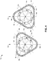
- FIG. 2 illustrates an example of a sensing system 50.
- the sensing system 50 can correspond to the sensing system 12 in the example of FIG. 1 . Therefore, reference is to be made to the example of FIG. 1 in the following description of the example of FIG. 2 .
- the sensing system 50 includes a resonator 52 that substantially surrounds a plurality of electrodes.
- the resonator 52 can be configured as an elastic hemispherical shell, but could have other geometric arrangements (e.g., an elastic ring).
- the plurality of electrodes includes a first electrode 54, a second electrode 56, a third electrode 58, a fourth electrode 60, a fifth electrode 62, a sixth electrode 64, a seventh electrode 66, and an eighth electrode 68.
- the electrodes 54, 56, 58, 60, 62, 64, 66, and 68 are demonstrated as arranged in an oppositely-disposed symmetrical annular arrangement about a sensitive axis 70, demonstrated as perpendicular to the plane of the page of FIG.
- the sensing system 50 is not limited to eight electrodes, or an oppositely-disposed symmetrical annular arrangement of the electrodes 54, 56, 58, 60, 62, 64, 66, and 68 about the sensitive axis 70.
- the electrodes 54, 56, 58, 60, 62, 64, 66, and 68 are provided signals ⁇ that can correspond to forcer signals and/or pickoff signals.
- a first signal ⁇ 0 is demonstrated as being provided to the first electrode 54
- a second signal ⁇ 1 is demonstrated as being provided to the second electrode 56
- a third signal ⁇ 3 is demonstrated as being provided to the third electrode 58
- a fourth signal ⁇ 3 is demonstrated as being provided to the fourth electrode 60.
- a fifth signal ⁇ 4 is demonstrated as being provided to the fifth electrode 62
- a sixth signal ⁇ 5 is demonstrated as being provided to the sixth electrode 64
- a seventh signal ⁇ 6 is demonstrated as being provided to the seventh electrode 66
- an eighth signal ⁇ 7 is demonstrated as being provided to the eighth electrode 68. While the example of FIG.
- a signal ⁇ is provided to each of the electrodes 54, 56, 58, 60, 62, 64, 66, and 68
- a proper subset of the signals ⁇ can be provided as forcer voltages ⁇ to a respective proper subset of the electrodes 54, 56, 58, 60, 62, 64, 66, and 68, such as in the example of some of the electrodes 54, 56, 58, 60, 62, 64, 66, and 68 being dedicated to pickoff.
- the electrodes 54, 56, 58, 60, 62, 64, 66, and 68 can provide an electrostatic force that acts upon the resonator 52.
- the resonator 52 is electrostatically attracted to the electrodes 54, 56, 58, 60, 62, 64, 66, and 68 based on a relative phase of the forcer voltages ⁇ , and thus a relative phase of the electrostatic forces.
- the forcer voltages ⁇ can, for example, have two separate sets of signals modulated together and applied at separate frequencies (e.g., across one or more orders of magnitude) and concurrently applied to the electrodes 54, 56, 58, 60, 62, 64, 66, and 68.
- the resonator 52 is deformed in each of two or more vibration pattern modes.
- the state of the resonator 52 in response to the application of the forcer voltages ⁇ is demonstrated in the examples of FIGS. 3 and 4 .
- the first state is demonstrated in the example of FIG. 4 at 152 and the second state is demonstrated at 154.
- the resonator 52 is demonstrated as being extended and contracted along three 120° axes, demonstrated as 156, 158, and 160, which are relative to the axes 106, 108, 110, and 112 defined by the electrodes 54, 56, 58, 60, 62, 64, 66, and 68.
- the axis 156 is demonstrated as being collinear with the axis 108.
- FIG. 5 illustrates an example of a three-axis gyroscope system 200 in accordance with an aspect of the invention.
- the three-axis gyroscope system 200 can be implemented in any of a variety of navigation control systems, such as for aircraft and/or spacecraft, or device to monitor yaw, pitch, and roll rotational motion information.
- the three-axis gyroscope system 200 includes an X-axis gyroscope system 202, a Y-axis gyroscope system 204, and a Z-axis gyroscope system 206.
- each of the X-axis, Y-axis, and Z-axis gyroscope systems 202, 204, and 206 can be configured substantially similar to the resonator gyroscope 10 in the example of FIG. 1 .
- FIG. 1 In the example of FIG.
- the X-axis gyroscope system 202 can have a sensitive axis about the X-axis
- the Y-axis gyroscope system 204 can have a sensitive axis about the Y-axis
- the Z-axis gyroscope system 206 can have a sensitive axis about the Z-axis.
- the sensitive axes of rotation of the respective resonator gyroscopes 202, 204, and 206 are indicated in the example of FIG. 5 by a Cartesian coordinate system 208.
- each of the X-axis, Y-axis, and Z-axis gyroscope systems 202, 204, and 206 are demonstrated as outputting signals that include the respective rotation measurements ROT X , ROT Y , and ROT Z to a motion sensor 210.
- the motion sensor 210 can thus be configured to determine an aggregate three-axis rotational motion of the associated vehicle or device that includes the three-axis gyroscope system 200. Therefore, the yaw, pitch, and roll of the associated vehicle or device that includes the three-axis gyroscope system 200 can be determined. Accordingly, the motion sensor 210 can be configured to display, output, and/or report the three-axis rotational motion of the associated vehicle or device that includes the three-axis gyroscope system 200.
- Each of the X-axis, Y-axis, and Z-axis resonator gyroscopes 202, 204, and 206 can include electrodes that are configured to generate electrostatic force in response to forcer signals (e.g., the forcer signals FRC) provided by respective controllers to provide deformation or motion of respective resonators, such as to provide a periodic motion of each of the respective resonators in a plurality of vibration pattern modes concurrently.
- forcer signals e.g., the forcer signals FRC
- the three-axis gyroscope system 200 can provide the rotation measurements ROT X , ROT Y , and ROT Z about all three of the sensitive axes, and can be calibrated in each of the three orthogonal axes substantially concurrently to provide the rotation measurements ROT X , ROT Y , and ROT Z about all three of the sensitive axes in a more accurate and uninterrupted manner, similar to as described previously.
- each of the X-axis, Y-axis, and Z-axis gyroscope systems 202, 204, and 206 can provide redundant calibrations of the X-axis, Y-axis, and Z-axis gyroscope systems 202, 204, and 206 or the rotation measurements ROT X , ROT Y , and ROT Z about the respective X-axis, Y-axis, and Z-axis gyroscope systems 202, 204, and 206 in a redundant manner, similar to as described previously.
- the three-axis gyroscope system 200 can be implemented instead of typical three-axis gyroscope systems that require four or six separate gyroscopes to provide calibration and measurement in all three respective axes.
- FIG. 6 a method in accordance with various aspects of the present disclosure will be better appreciated with reference to FIG. 6 . While, for purposes of simplicity of explanation, the method of FIG. 6 is shown and described as executing serially, it is to be understood and appreciated that the present disclosure is not limited by the illustrated order, as some aspects could, in accordance with the present disclosure, occur in different orders and/or concurrently with other aspects from that shown and described herein. Moreover, not all illustrated features may be required to implement a method in accordance with an aspect of the present disclosure.
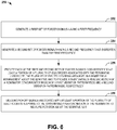
- FIG. 6 illustrates a method 250 for controlling a resonator gyroscope (e.g., the resonator gyroscope 10).
- a first set of forcer signals e.g., the forcer signals FRC 1
- a second set of forcer signals e.g., the forcer signals FRC 2
- each of the first and second sets of forcer signals is provided concurrently to at least a portion of a plurality of electrodes (e.g., the electrodes 18) associated with the resonator gyroscope.
Abstract
Description
- This disclosure relates generally to sensing systems, and more specifically to a self-calibrating resonator gyroscope.
- There are a number different types of gyroscopes that are configured to calculate rotation about a sensitive (i.e., input) axis. One type of gyroscope is a Coriolis vibratory gyroscope (CVG). One example of a CVG is a tuning fork gyroscope in which two masses (e.g. tines) can vibrate in plane along a drive axis. In response to an applied angular rate about an input axis parallel to the tines of the tuning fork, Coriolis forces cause the tines to vibrate out of plane along a sense axis (e.g., 90° relative to a drive axis). The amplitude of the out-of-plane motion in open loop instruments or the force required to rebalance and null the out-of-plane motion in closed-loop instruments can correspond to a measure of the angular rate applied about the input axis. Another example of a CVG is a Resonator gyroscope in which a "wine glass" shaped resonator is caused to vibrate at a fundamental resonant frequency. In a fundamental or N=2 mode, the displacement of points on the vibrating resonator is in the form of a standing wave with antinodes and nodes that are separated by 45° in the circumferential direction. In force-rebalance operation, one of the antinodes can be maintained along a drive axis. In a resonator gyroscope, an angular rotation applied about the axis of symmetry of the resonator (e.g., input axis) can cause the standing wave to lag in angular displacement relative to the housing, which can thus be indicative of rotation of the resonator gyroscope about the sensitive axis.
- One example includes a resonator gyroscope. The resonator gyroscope includes a sensing system comprising a plurality of electrodes arranged about a sensitive axis and configured to electrostatically force a resonator into a substantially periodic motion based on a plurality of forcer signals applied to the plurality of electrodes, and configured to provide an indication of rotation about a sensitive axis of the resonator gyroscope. The resonator gyroscope further includes a controller configured to generate the plurality of forcer signals to provide the substantially periodic motion of the resonator concurrently in each of a plurality of separate vibration pattern modes to measure the rotation of the resonator gyroscope about the sensitive axis in response to a plurality of pickoff signals associated with the substantially periodic motion. In an embodiment the resonator gyroscope is configured as a hemispherical resonator gyroscope.
- Another example includes a method for controlling a resonator gyroscope. The method includes generating a first set of forcer signals having a first frequency and generating a second set of forcer signals having a second frequency that is greater than the first frequency. The method also includes providing each of the first and second sets of forcer signals concurrently to at least a portion of a plurality of electrodes associated with the resonator gyroscope. The plurality of electrodes can be arranged about the sensitive axis to provide a substantially periodic motion of a resonator concurrently in each of a first vibration pattern mode and a second vibration pattern mode, respectively. The method further includes measuring pickoff signals associated with at least a portion of the plurality of electrodes in response to the substantially periodic motion of the resonator to measure rotation about the sensitive axis.
- Another example includes a multi-axis gyroscope system. The system includes a first resonator gyroscope configured to measure rotation of the multi-axis gyroscope system about an X-axis, a second resonator gyroscope configured to measure rotation of the multi-axis gyroscope system about a Y-axis, and a third resonator gyroscope configured to measure rotation of the multi-axis gyroscope system about a Z-axis. Each of the first, second, and third resonator gyroscopes includes a sensing system comprising a plurality of electrodes arranged about the respective one of the X, Y, and Z axes and configured to electrostatically force a resonator into a substantially periodic motion based on a plurality of forcer signals applied to the plurality of electrodes, and configured to provide an indication of rotation about the respective one of the X, Y, and Z axes of the respective one of the first, second, and third resonator gyroscopes. Each of the first, second, and third resonator gyroscopes also includes a controller configured to generate the plurality of forcer signals to provide the substantially periodic motion of the resonator concurrently in each of a plurality of separate vibration pattern modes to measure the rotation of the respective one of the first, second, and third resonator gyroscopes about the respective one of the X, Y, and Z axes in response to a plurality of pickoff signals associated with the substantially periodic motion. In an embodiment the controller is configured to alternate between calibration of the respective one of the first, second, and third resonator gyroscopes via the second of the vibration pattern modes while measuring the rotation of the respective one of the first, second, and third resonator gyroscopes about the respective one of the X, Y, and Z axes via the first of the vibration pattern modes and calibration of the respective one of the first, second, and third resonator gyroscopes via the first of the vibration pattern modes while measuring the rotation of the respective one of the first, second, and third resonator gyroscopes about the respective one of the X, Y, and Z axes via the second of the vibration pattern modes. In another embodiment the controller is configured to provide a first measurement of the rotation about the respective one of the X, Y, and Z axes of the respective one of the first, second, and third resonator gyroscopes in a force rebalance manner via a first of the vibration pattern modes and to provide a second measurement of the rotation about the respective one of the X, Y, and Z axes of the respective one of the first, second, and third resonator gyroscopes in a whole angle manner via a second of the vibration pattern modes, wherein the controller is further configured to implement an algorithm to combine the first and second measurements to measure the rotation of the respective one of the first, second, and third resonator gyroscopes about the respective one of the X, Y, and Z axes. In another embodiment the controller is configured to provide a first calibration of the respective one of the first, second, and third resonator gyroscopes via a first of the vibration pattern modes concurrently with a second calibration of the respective one of the first, second, and third resonator gyroscopes via a second of the vibration pattern modes, wherein the controller is further configured to implement an algorithm to combine the first and second calibrations to calibrate the respective one of the first, second, and third resonator gyroscopes.
-
-
FIG. 1 illustrates an example of a resonator gyroscope. -
FIG. 2 illustrates an example of a sensing system. -
FIG. 3 illustrates an example diagram of periodic motion of a sensing system. -
FIG. 4 illustrates another example diagram of periodic motion of a sensing system. -
FIG. 5 illustrates an example of a multi-axis resonator gyroscope. -
FIG. 6 illustrates an example of a method for controlling a resonator gyroscope. - This disclosure relates generally to sensing systems, and specifically to a self-calibrating resonator gyroscope. A resonator gyroscope can include a sensing system and a controller. The sensing system includes a plurality of electrodes (e.g., eight electrodes) arranged about a sensitive axis. The electrodes are configured to electrostatically force a resonator (e.g., a hemispherical resonator) into a substantially periodic motion based on the application of the forcer signals to the electrodes. The electrodes can also be configured to provide an indication of rotation about a sensitive axis of the resonator gyroscope based on pickoff signals. The controller can generate the forcer signals to provide the substantially periodic motion of the resonator concurrently in each of a plurality of separate vibration pattern modes. The vibration pattern modes can correspond to, for example, an N=2 vibration pattern mode and an N=3 vibration pattern mode. As an example, the forcer signals can be generated to have separate frequencies, such that the vibration pattern modes do not interfere with each other with respect to the forcer signals and the associated pickoff signals.
- Based on the operation of the forcer signals to provide the substantially periodic motion of the resonator in each of the vibration pattern modes concurrently, the resonator gyroscope can provide efficient and accurate operation. As a first example, the resonator gyroscope can operate to measure rotation of the resonator gyroscope about the sensitive axis via first pickoff signals associated with a first vibration pattern mode while concurrently being calibrated (e.g., via a calibration signal) via second pickoff signals associated with the second vibration pattern mode. As another example, the resonator gyroscope can operate to measure rotation of the resonator gyroscope about the sensitive axis in a force-rebalance manner via the first pickoff signals associated with the first vibration pattern mode while concurrently measuring rotation of the resonator gyroscope about the sensitive axis in a whole-angle manner via the second pickoff signals associated with the second vibration pattern mode. As yet another example, the resonator gyroscope can be calibrated via the first pickoff signals associated with the first vibration pattern mode while concurrently being calibrated via the second pickoff signals associated with the second vibration pattern mode. Therefore, the resonator gyroscope can operate in a variety of ways based on operating concurrently in separate vibration pattern modes.
-
FIG. 1 illustrates an example of aresonator gyroscope 10. Theresonator gyroscope 10 can correspond to any of a variety of different types of gyroscopes that implement vibratory motion, such as a Coriolis vibratory gyroscope (CVG). Theresonator gyroscope 10 can be implemented in any of a variety of applications with which accurate measurement of rotation about a sensitive axis may be necessary, such as aerospace and nautical navigation. Theresonator gyroscope 10 includes asensing system 12 and acontroller 14. - The
sensing system 12 includes aresonator 16 that can be arranged as a deformable material having an elastic property and being provided in one of a variety of different forms. For example, theresonator 16 can be an elastic hemisphere, an elastic ring, a disk, or any of a variety of other types of resonators that can provide periodic motion in an axi-symmetric manner with respect to the sensitive axis. Thesensing system 12 also includes a set ofelectrodes 18 that are arranged with respect to theresonator 16. For example, theelectrodes 18 can be arranged in an annular arrangement between the sensitive axis and theresonator 16, such that theresonator 16 substantially surrounds theelectrodes 18. Theelectrodes 18 are configured to generate electrostatic force in response to forcer signals FRC provided by thecontroller 14 to provide deformation or motion of theresonator 16, such as to provide a periodic motion of theresonator 16 in a plurality of vibration pattern modes concurrently. - For example, the vibration pattern modes can include an N=2 vibration pattern mode and an N=3 vibration pattern mode. As described herein, the term "N" describes half the number of antinodes of the vibration pattern mode. Therefore, the N=2 vibration pattern mode describes four antinodes of the
resonator 16 along four substantially equally angularly-separated principle axes, and the N=3 vibration pattern mode provides for six antinodes of theresonator 16 along six substantially equally angularly-separated principle axes. Alternatively, other vibration pattern modes (e.g., N=1, 4, 5, ...) can be implemented. As an example, the vibration pattern modes can be provided via the forcer signals FRC at different frequencies based on the frequencies of the forcer signals FRC. As an example, the frequencies of each of the separate sets of forcer signals can have a difference that is greater than a desired measurement bandwidth of theresonator gyroscope 10. Therefore, perturbations that affect the pickoff signals of only one of the vibration pattern modes does not affect the pickoff signals associated with other vibration pattern mode(s) across the frequency response of the associated pickoff signals. - As an example, the
electrodes 18 can be implemented to provide force-rebalance of the angular displacement of the standing wave on theresonator 16 and concurrently provide nulling of the quadrature effects that can degrade or otherwise affect the standing wave. In addition, theelectrodes 18 can include and/or can be implemented as pickoff electrodes that can provide pickoff signals PO corresponding to the motion of theresonator 16 to measure the rotation of thesensing system 12 about the sensitive axis, demonstrated in the example ofFIG. 1 as ROT. Thus, as a first example, theelectrodes 18 can include dedicated forcer electrodes and pickoff electrodes, or as a second example, theelectrodes 18 could implement dual forcer and pickoff functionality. - The
controller 14 includes aprocessor 22 and asignal generator 24. Thesignal generator 24 is configured to generate the forcer signals FRC that are provided to theelectrodes 18 based on the pickoff signals PO that are provided to the sensing system 12 (e.g., via the signal generator 24) for capacitive measurement of the of the deformation of theresonator 16 with respect to theelectrodes 18 via theprocessor 22. As an example, one set of the forcer signals FRC can be generated by thesignal generator 24 based on a set of equations, such as described inU.S. Patent Application No. 15/296,774 (Attorney Docket No. NG(NSD)-025345), which is incorporated herein by reference in its entirety. Therefore, the forcer signals FRC can be generated to provide a non-integer ratio between the number ofelectrodes 18 and the vibration pattern mode, such as based on implementing an N=3 vibration pattern mode with eightelectrodes 18. In addition, thecontroller 14 includes a calibration component 26 that is configured to generate a calibration signal CAL. As an example, the calibration signal CAL can correspond to any of a variety of methods of self-calibration of a resonator gyroscope, such as a predetermined signal injected into the force rebalance signals FRC to implement bias and/or scale-factor calibration, mode-reversal, or other types of self-calibration implementations, such as described inU.S. Patent Application No. 15/256,168 (Attorney Docket No. NG(NSD)-025094), which is incorporated herein by reference in its entirety. - As an example, the
controller 14 can be configured to measure the rotation ROT of theresonator gyroscope 10 about the sensitive axis in a force-rebalance manner and/or a whole-angle manner. For example, the forcer signals FRC can be provided to a first portion of theelectrodes 18 to provide the periodic motion of theresonator 16 in response to one or more of the pickoff signals PO. The pickoff signals PO can be provided to theprocessor 22 that generates the forcer signals FRC, such as based on disparate phases of respective resultant electrostatic forces provided via theelectrodes 18. Thus, the forcer signals FRC can control the amplitudes of the electrostatic forces and provide a measure of the rate of angular rotation ROT of thesensing system 12 about the sensitive axis (e.g., in the example of force-rebalance operation), and also control quadrature effects. Thus, thecontroller 14 can provide the measurement of the angular rate of rotation ROT about the input axis as an output signal ROT based on the pickoff signals. - Based on the operation of the forcer signals FRC to provide the substantially periodic motion of the
resonator 16 in each of the vibration pattern modes concurrently, theresonator gyroscope 10 can provide efficient and accurate operation. As an example, thecontroller 14 can measure rotation ROT of theresonator gyroscope 10 about the sensitive axis via first pickoff signals PO1 associated with a first vibration pattern mode (e.g., N=2) while concurrently being calibrated (e.g., via the calibration signal CAL that can control or dictate one of a variety of different calibration methods) via second pickoff signals PO2 associated with the second vibration pattern mode (e.g., N=3). For example, thecontroller 14 can be configured to measure rotation ROT of theresonator gyroscope 10 about the sensitive axis via the first pickoff signals PO1 associated with a first vibration pattern mode and concurrently calibrate theresonator gyroscope 10 via the second pickoff signals PO2 associated with the second vibration pattern mode during a first time duration. Thecontroller 14 can thus calibrate theresonator gyroscope 10 via the first pickoff signals PO1 associated with the first vibration pattern mode and concurrently measure rotation ROT of theresonator gyroscope 10 about the sensitive axis via the second pickoff signals PO2 associated with second vibration pattern mode during a second time duration. Accordingly, thecontroller 14 can substantially continuously alternate between the first time duration and the second time duration, such that theresonator gyroscope 10 can be substantially continuously calibrated and can continue to measure the rotation ROT of theresonator gyroscope 10 about the sensitive axis in an uninterrupted manner. - As a second example, the
controller 14 can operate to obtain a first measurement of rotation ROT of theresonator gyroscope 10 about the sensitive axis in a force-rebalance manner via the first pickoff signals PO1 associated with the first vibration pattern mode while concurrently obtaining a second measurement of rotation ROT of the resonator gyroscope about the sensitive axis in a whole-angle manner via the second pickoff signals PO2 associated with the second vibration pattern mode. The force-rebalance manner can thus correspond to one manner of calculating rotation ROT of theresonator gyroscope 10 about the sensitive axis, while the whole-angle manner (e.g., integration manner) can correspond to another different manner of calculating rotation ROT of theresonator gyroscope 10 about the sensitive axis. As an example, theprocessor 22 can be configured to implement an algorithm that is configured to combine the first and second measurements to measure the rotation ROT of theresonator gyroscope 10 about the sensitive axis. Therefore, theprocessor 22 can generate a single measurement of the rotation ROT of theresonator gyroscope 10 about the sensitive axis based on the first and second measurements of the rotation ROT of theresonator gyroscope 10 about the sensitive axis. For example, the algorithm can be configured to provide integration of the first and second measurements, statistical analysis/comparison of the first and second measurements, or any other ways to combine the first and second measurements to obtain a single measurement of the rotation ROT of theresonator gyroscope 10 about the sensitive axis. Such redundant measurement of rotation ROT can thus provide a more accurate and/or improved performance of the measurement of the rotation ROT of theresonator gyroscope 10 about the sensitive axis, and/or can provide improved stability with respect to bias and/or scale-factor errors. - As yet another example, the
controller 14 can be configured to obtain a calibration of theresonator gyroscope 10 via the first pickoff signals PO1 associated with the first vibration pattern mode while concurrently obtaining a calibration of theresonator gyroscope 10 via the second pickoff signals PO2 associated with the second vibration pattern mode. For example, the calibration component 26 can be configured to provide the same or different calibration methodologies (e.g., self-calibration, mode reversal, signal-injection, or other calibration techniques) to calibrate theresonator gyroscope 10 in each of the first and second vibration pattern modes (e.g., via the signal(s) CAL). Furthermore, thecontroller 14 can be configured to implement any combination of and/or alternate between the measurement and calibration procedures described herein. For example, thecontroller 14 can provide any combination of measuring rotation ROT of theresonator gyroscope 10 about the sensitive axis in each of the first and second vibration pattern modes, measuring the rotation ROT of theresonator gyroscope 10 about the sensitive axis in one of the vibration pattern modes while concurrently calibrating theresonator gyroscope 10 in another of the vibration pattern modes, and calibrating theresonator gyroscope 10 in both of the vibration pattern modes. Accordingly, theresonator gyroscope 10 can operate in a variety of ways based on operating concurrently in separate vibration pattern modes. -
FIG. 2 illustrates an example of asensing system 50. Thesensing system 50 can correspond to thesensing system 12 in the example ofFIG. 1 . Therefore, reference is to be made to the example ofFIG. 1 in the following description of the example ofFIG. 2 . - The
sensing system 50 includes aresonator 52 that substantially surrounds a plurality of electrodes. As an example, theresonator 52 can be configured as an elastic hemispherical shell, but could have other geometric arrangements (e.g., an elastic ring). The plurality of electrodes includes afirst electrode 54, asecond electrode 56, athird electrode 58, afourth electrode 60, afifth electrode 62, asixth electrode 64, aseventh electrode 66, and aneighth electrode 68. Theelectrodes sensitive axis 70, demonstrated as perpendicular to the plane of the page ofFIG. 2 , and thus perpendicular to the axes associated with the vibration pattern mode, as described in greater detail herein. However, it is to be understood that thesensing system 50 is not limited to eight electrodes, or an oppositely-disposed symmetrical annular arrangement of theelectrodes sensitive axis 70. - In the example of
FIG. 2 , theelectrodes first electrode 54, a second signal ε1 is demonstrated as being provided to thesecond electrode 56, a third signal ε3 is demonstrated as being provided to thethird electrode 58, and a fourth signal ε3 is demonstrated as being provided to thefourth electrode 60. Similarly, a fifth signal ε4 is demonstrated as being provided to the fifth
electrode 62, a sixth signal ε5 is demonstrated as being provided to thesixth electrode 64, a seventh signal ε6 is demonstrated as being provided to theseventh electrode 66, and an eighth signal ε7 is demonstrated as being provided to theeighth electrode 68. While the example ofFIG. 2 demonstrates that a signal ε is provided to each of theelectrodes electrodes electrodes - In response to the application of the signals ε provided as forcer voltages, the
electrodes resonator 52. In response, theresonator 52 is electrostatically attracted to theelectrodes electrodes resonator 52 is deformed in each of two or more vibration pattern modes. For example, a first set of forcer voltages ε can provide an N=2 vibration pattern mode at a first frequency, and a second set of forcer voltages ε can provide an N=3 vibration pattern mode. The state of theresonator 52 in response to the application of the forcer voltages ε is demonstrated in the examples ofFIGS. 3 and4 . -
FIG. 3 illustrates another example diagram 100 of N=2 periodic motion of thesensing system 50. Due to the elastic property of theresonator 52, theresonator 52 can rebound at approximately half of a period of the resonant frequency. In response, theresonator 52 oscillates between a first state corresponding to a time T=0 and a second state corresponding to a time T=1/2F1, where F1 is the vibration frequency of the first vibration pattern mode. The first state is demonstrated in the example ofFIG. 3 at 102 and the second state is demonstrated at 104. In thefirst state 102, corresponding to the time T=0, theresonator 52 is demonstrated as being extended and contracted along two orthogonal axes, demonstrated as 106 and 108, and also demonstrates two otherorthogonal axes axes axes electrodes FIG. 3 demonstrates the motion and application of forcer and pickoff signals that correspond to the N=2 vibration pattern mode. -
FIG. 4 illustrates an example diagram 150 of N=3 periodic motion of thesensing system 50. Due to the elastic property of theresonator 52, theresonator 52 can rebound at approximately half of a period of the resonant frequency. In response, theresonator 52 oscillates between a first state corresponding to a time T=0 and a second state corresponding to a time T=1/2F2, where F2 is the vibration frequency of the second vibration pattern mode, which is different from the vibration frequency F1. The first state is demonstrated in the example ofFIG. 4 at 152 and the second state is demonstrated at 154. In the first state 152, corresponding to the time T=0, theresonator 52 is demonstrated as being extended and contracted along three 120° axes, demonstrated as 156, 158, and 160, which are relative to theaxes electrodes FIG. 4 , theaxis 156 is demonstrated as being collinear with theaxis 108. Alternatively, theaxis 156 can be collinear with theaxis 106. Therefore, the example ofFIG. 4 demonstrates the motion and application of forcer and pickoff signals that correspond to the second vibration pattern mode corresponding to the N=3 vibration pattern mode, which can thus operate concurrently with the N=2 vibration pattern mode demonstrated in the example ofFIG. 3 . -
FIG. 5 illustrates an example of a three-axis gyroscope system 200 in accordance with an aspect of the invention. As an example, the three-axis gyroscope system 200 can be implemented in any of a variety of navigation control systems, such as for aircraft and/or spacecraft, or device to monitor yaw, pitch, and roll rotational motion information. - The three-
axis gyroscope system 200 includes anX-axis gyroscope system 202, a Y-axis gyroscope system 204, and a Z-axis gyroscope system 206. As an example, each of the X-axis, Y-axis, and Z-axis gyroscope systems resonator gyroscope 10 in the example ofFIG. 1 . In the example ofFIG. 5 , theX-axis gyroscope system 202 can have a sensitive axis about the X-axis, the Y-axis gyroscope system 204 can have a sensitive axis about the Y-axis, and the Z-axis gyroscope system 206 can have a sensitive axis about the Z-axis. The sensitive axes of rotation of therespective resonator gyroscopes FIG. 5 by a Cartesian coordinatesystem 208. - In the example of
FIG. 5 , each of the X-axis, Y-axis, and Z-axis gyroscope systems motion sensor 210. Themotion sensor 210 can thus be configured to determine an aggregate three-axis rotational motion of the associated vehicle or device that includes the three-axis gyroscope system 200. Therefore, the yaw, pitch, and roll of the associated vehicle or device that includes the three-axis gyroscope system 200 can be determined. Accordingly, themotion sensor 210 can be configured to display, output, and/or report the three-axis rotational motion of the associated vehicle or device that includes the three-axis gyroscope system 200. - Each of the X-axis, Y-axis, and Z-
axis resonator gyroscopes axis gyroscope system 200 can provide the rotation measurements ROTX, ROTY, and ROTZ about all three of the sensitive axes, and can be calibrated in each of the three orthogonal axes substantially concurrently to provide the rotation measurements ROTX, ROTY, and ROTZ about all three of the sensitive axes in a more accurate and uninterrupted manner, similar to as described previously. Additionally or alternatively, each of the X-axis, Y-axis, and Z-axis gyroscope systems axis gyroscope systems axis gyroscope systems axis gyroscope system 200 can be implemented instead of typical three-axis gyroscope systems that require four or six separate gyroscopes to provide calibration and measurement in all three respective axes. - In view of the foregoing structural and functional features described above, a method in accordance with various aspects of the present disclosure will be better appreciated with reference to
FIG. 6 . While, for purposes of simplicity of explanation, the method ofFIG. 6 is shown and described as executing serially, it is to be understood and appreciated that the present disclosure is not limited by the illustrated order, as some aspects could, in accordance with the present disclosure, occur in different orders and/or concurrently with other aspects from that shown and described herein. Moreover, not all illustrated features may be required to implement a method in accordance with an aspect of the present disclosure. -
FIG. 6 illustrates amethod 250 for controlling a resonator gyroscope (e.g., the resonator gyroscope 10). At 252, a first set of forcer signals (e.g., the forcer signals FRC1) having a first frequency is generated. At 254, a second set of forcer signals (e.g., the forcer signals FRC2) having a second frequency that is greater than the first frequency is generated. At 256, each of the first and second sets of forcer signals is provided concurrently to at least a portion of a plurality of electrodes (e.g., the electrodes 18) associated with the resonator gyroscope. The plurality of electrodes can be arranged about the sensitive axis to provide a substantially periodic motion of a resonator (e.g., the resonator 16) concurrently in each of a first vibration pattern mode (e.g., an N=2 vibration pattern mode) and a second vibration pattern mode (e.g., an N=3 vibration pattern mode), respectively. At 258, pickoff signals (e.g., the pickoff signals PO) associated with at least a portion of the plurality of electrodes are measured in response to the substantially periodic motion of the resonator to measure rotation about the sensitive axis. - What have been described above are examples of the disclosure. It is, of course, not possible to describe every conceivable combination of components or method for purposes of describing the disclosure, but one of ordinary skill in the art will recognize that many further combinations and permutations of the disclosure are possible. Accordingly, the disclosure is intended to embrace all such alterations, modifications, and variations that fall within the scope of this application, including the appended claims.
Claims (15)
- A resonator gyroscope (10) comprising:a sensing system (12, 50) comprising a plurality of electrodes (18, 54, 56, 58, 60, 62, 64, 66, 68) arranged about a sensitive axis (70) and configured to electrostatically force a resonator (16) into a substantially periodic motion based on a plurality of forcer signals (FRC) applied to the plurality of electrodes (18, 54, 56, 58, 60, 62, 64, 66, 68), and configured to provide an indication of rotation (ROT) about a sensitive axis (70) of the resonator gyroscope (10); anda controller (14) configured to generate the plurality of forcer signals (FRC) to provide the substantially periodic motion of the resonator (16) concurrently in each of a plurality of separate vibration pattern modes to measure the rotation (ROT) of the resonator gyroscope (10) about the sensitive axis (70) in response to a plurality of pickoff signals (PO) associated with the substantially periodic motion.
- The resonator gyroscope (10) of claim 1, wherein the vibration pattern modes comprise a first vibration pattern mode having a first frequency and a second vibration pattern mode having a second frequency that is greater than the first frequency.
- The resonator gyroscope (10) of claim 1, wherein the vibration pattern modes comprise an N=2 vibration pattern mode and an N=3 vibration pattern mode.
- The resonator gyroscope (10) of claim 1, wherein the controller (14) is configured to measure the rotation (ROT) about the sensitive axis (70) of the resonator gyroscope (10) in response to the plurality of pickoff signals (PO) in a first of the vibration pattern modes and to concurrently facilitate calibration of the resonator gyroscope (10) in a second of the vibration pattern modes.
- The resonator gyroscope (10) of claim 4, wherein the controller (14) is configured to alternate between calibration of the resonator gyroscope (10) via the second of the vibration pattern modes while measuring the rotation (ROT) of the resonator gyroscope (10) about the sensitive axis (70) via the first of the vibration pattern modes and calibration of the resonator gyroscope (10) via the first of the vibration pattern modes while measuring the rotation (ROT) of the resonator gyroscope (10) about the sensitive axis (70) via the second of the vibration pattern modes.
- The resonator gyroscope (10) of claim 1, wherein the controller (14) is configured to provide a first measurement of the rotation about the sensitive axis (70) of the resonator gyroscope (10) in a force rebalance manner via a first of the vibration pattern modes and to provide a second measurement of the rotation about the sensitive axis (70) of the resonator gyroscope (10) in a whole angle manner via a second of the vibration pattern modes, wherein the controller (14) is further configured to implement an algorithm to combine the first and second measurements to measure the rotation of the resonator gyroscope (10) about the sensitive axis (70).
- The resonator gyroscope (10) of claim 1, wherein the controller (14) is configured to provide a first calibration of the resonator gyroscope (10) via a first of the vibration pattern modes concurrently with a second calibration of the resonator gyroscope (10) via a second of the vibration pattern modes, wherein the controller (14) is further configured to implement an algorithm to combine the first and second calibrations to calibrate the resonator gyroscope (10).
- The resonator gyroscope (10) of claim 1, wherein the controller (14) is configured to generate the plurality of forcer signals (FRC) to provide the vibratory resonant motion of the resonator (16) in an axi-symmetric manner with respect to the sensitive axis (70).
- A multi-axis gyroscope system (200) comprising the resonator gyroscope (10) of claim 1 configured as a first resonator gyroscope (202) configured to measure rotation (ROT) of the multi-axis gyroscope system (200) about an X-axis, the multi-axis gyroscope system (200) further comprising:a second resonator gyroscope (204) configured to measure rotation (ROT) of the multi-axis gyroscope system (200) about a Y-axis; anda third resonator gyroscope (206) configured to measure rotation (ROT) of the multi-axis gyroscope system (200) about a Z-axis.
- A method (250) for controlling a resonator gyroscope (10), the method comprising:generating (252) a first set of forcer signals (FRC) having a first frequency;generating (254) a second set of forcer signals (FRC) having a second frequency that is greater than the first frequency;providing (256) each of the first and second sets of forcer signals (FRC) concurrently to at least a portion of a plurality of electrodes (18, 54, 56, 58, 60, 62, 64, 66, 68) associated with the resonator gyroscope (10), the plurality of electrodes (18, 54, 56, 58, 60, 62, 64, 66, 68) being arranged about the sensitive axis (70) to provide a substantially periodic motion of a resonator (16) concurrently in each of a first vibration pattern mode and a second vibration pattern mode, respectively; andmeasuring (258) pickoff signals (PO) associated with at least a portion of the plurality of electrodes in response to the substantially periodic motion of the resonator (16) to measure rotation (ROT) about the sensitive axis (70).
- The method (250) of claim 10, wherein providing the substantially periodic motion of the resonator (16) comprises providing the substantially periodic motion of the resonator (16) concurrently in each of an N=2 vibration pattern mode and an N=3 vibration pattern mode vibration.
- The method (250) of claim 10, wherein measuring the pickoff signals (PO) comprises measuring the rotation (ROT) of the resonator gyroscope (10) about the sensitive axis (70) in response to first pickoff signals associated with the first vibration pattern mode and concurrently measuring second pickoff signals associated with the second vibration pattern mode to calibrate the resonator gyroscope (10) in response to a calibration signal.
- The method (250) of claim 10, wherein measuring the pickoff signals (PO) comprises:measuring the rotation (ROT) of the resonator gyroscope (10) about the sensitive axis (70) in response to first pickoff signals associated with the first vibration pattern mode and concurrently measuring second pickoff signals associated with the second vibration pattern mode to calibrate the resonator gyroscope (10) in response to a calibration signal;measuring the rotation (ROT) of the resonator gyroscope (10) about the sensitive axis (70) in response to the second pickoff signals and concurrently measuring the second pickoff signals to calibrate the resonator gyroscope (10) in response to the calibration signal; andsequentially alternating between the first time duration and the second time duration.
- The method (250) of claim 10, wherein measuring the pickoff signals (PO) comprises:obtaining a first measurement of the rotation (ROT) of the resonator gyroscope (10) about the sensitive axis (70) in response to first pickoff signals associated with the first vibration pattern mode in a force rebalance manner and concurrently obtaining a second measurement of the rotation (ROT) of the resonator gyroscope (10) about the sensitive axis (70) in response to second pickoff signals associated with the second vibration pattern mode in a whole-angle manner; andcombining the first and second measurements via an algorithm to measure the rotation (ROT) of the resonator gyroscope (10) about the sensitive axis (70).
- The method (250) of claim 10, wherein measuring the pickoff signals (PO) comprises:measuring first pickoff signals associated with the first vibration pattern mode to obtain a first calibration of the resonator gyroscope (10) in response to a first calibration signal and concurrently measuring second pickoff signals associated with the second vibration pattern mode to obtain a second calibration of the resonator gyroscope (10) in response to a second calibration signal; andcombining the first and second calibrations via an algorithm to measure the rotation (ROT) of the resonator gyroscope (10) about the sensitive axis (70).
Applications Claiming Priority (1)
| Application Number | Priority Date | Filing Date | Title |
|---|---|---|---|
| US15/368,206 US20180156634A1 (en) | 2016-12-02 | 2016-12-02 | Dual-vibratory pattern resonator gyroscope |
Publications (3)
| Publication Number | Publication Date |
|---|---|
| EP3330665A2 true EP3330665A2 (en) | 2018-06-06 |
| EP3330665A3 EP3330665A3 (en) | 2018-07-18 |
| EP3330665B1 EP3330665B1 (en) | 2022-07-06 |
Family
ID=60409221
Family Applications (1)
| Application Number | Title | Priority Date | Filing Date |
|---|---|---|---|
| EP17202551.2A Active EP3330665B1 (en) | 2016-12-02 | 2017-11-20 | Dual-mode vibratory resonator gyroscope |
Country Status (3)
| Country | Link |
|---|---|
| US (1) | US20180156634A1 (en) |
| EP (1) | EP3330665B1 (en) |
| JP (1) | JP6518752B2 (en) |
Families Citing this family (2)
| Publication number | Priority date | Publication date | Assignee | Title |
|---|---|---|---|---|
| US11073393B2 (en) | 2019-01-16 | 2021-07-27 | Northrop Grumman Systems Corporation | Coriolis vibratory gyroscope control system |
| US11073391B2 (en) | 2019-09-26 | 2021-07-27 | Northrop Grumman Systems Corporation | Coriolis vibratory accelerometer system |
Family Cites Families (8)
| Publication number | Priority date | Publication date | Assignee | Title |
|---|---|---|---|---|
| GB0001294D0 (en) * | 2000-01-20 | 2000-03-08 | British Aerospace | Multi-axis sensing device |
| WO2004085963A1 (en) * | 2003-03-28 | 2004-10-07 | Bae Systems Plc | A rate sensing device |
| US7739896B2 (en) * | 2007-03-15 | 2010-06-22 | Northrop Grumman Guidance And Electronics Company, Inc. | Self-calibration of scale factor for dual resonator class II coriolis vibratory gyros |
| US7912664B2 (en) * | 2008-09-11 | 2011-03-22 | Northrop Grumman Guidance And Electronics Company, Inc. | Self calibrating gyroscope system |
| US8996919B2 (en) * | 2012-03-13 | 2015-03-31 | Invensense, Inc. | Method and system providng a self-test on one or more sensors coupled to a device |
| FR2991044B1 (en) * | 2012-05-24 | 2014-05-09 | Sagem Defense Securite | INERTIAL PLATFORM WITH VIBRATION GYROSCOPES MOUNTED ON A CARROUSEL AND METHOD OF ANGULAR MEASUREMENT |
| US9671247B2 (en) * | 2014-07-16 | 2017-06-06 | Innalabs Limited | Method for calibrating vibratory gyroscope |
| WO2018048710A1 (en) * | 2016-09-09 | 2018-03-15 | Nextnav, Llc | Systems and methods for calibrating unstable sensors |
-
2016
- 2016-12-02 US US15/368,206 patent/US20180156634A1/en not_active Abandoned
-
2017
- 2017-11-20 EP EP17202551.2A patent/EP3330665B1/en active Active
- 2017-11-30 JP JP2017230285A patent/JP6518752B2/en active Active
Also Published As
| Publication number | Publication date |
|---|---|
| EP3330665B1 (en) | 2022-07-06 |
| EP3330665A3 (en) | 2018-07-18 |
| JP2018091845A (en) | 2018-06-14 |
| JP6518752B2 (en) | 2019-05-22 |
| US20180156634A1 (en) | 2018-06-07 |
Similar Documents
| Publication | Publication Date | Title |
|---|---|---|
| EP3312558B1 (en) | Hemispherical resonator gyroscope | |
| US7874209B2 (en) | Capacitive bulk acoustic wave disk gyroscopes with self-calibration | |
| EP2696169B1 (en) | Force-rebalance coriolis vibratory gyroscope | |
| EP1970669B1 (en) | Self-calibration of scale factor for dual resonator class II coriolis vibratory gyros | |
| US10436588B2 (en) | Vibrating-mass gyroscope systems and method | |
| US9874459B2 (en) | Actuation and sensing platform for sensor calibration and vibration isolation | |
| EP2017576B1 (en) | Combined accelerometer and gyroscope system | |
| US9476710B2 (en) | Axially symmetric Coriolis vibratory gyroscope (variants) | |
| US11390517B2 (en) | Systems and methods for bias suppression in a non-degenerate MEMS sensor | |
| WO2018157118A1 (en) | Calibration system and method for whole angle gyroscope | |
| KR20100024516A (en) | Coriolis gyro | |
| EP3330665B1 (en) | Dual-mode vibratory resonator gyroscope | |
| EP3495772B1 (en) | Vibrating-mass gyroscope system | |
| Maslov et al. | Methods to eliminate nonlinearity of electrostatic control sensors of the wave solid-state gyroscope | |
| Chikovani et al. | Errors Compensation of Ring-Type MEMS Gyroscopes Operating in Differential Mode | |
| CN117295926A (en) | Method for correcting measurements from an angular vibration inertial sensor |
Legal Events
| Date | Code | Title | Description |
|---|---|---|---|
| PUAI | Public reference made under article 153(3) epc to a published international application that has entered the european phase |
Free format text: ORIGINAL CODE: 0009012 |
|
| STAA | Information on the status of an ep patent application or granted ep patent |
Free format text: STATUS: THE APPLICATION HAS BEEN PUBLISHED |
|
| AK | Designated contracting states |
Kind code of ref document: A2 Designated state(s): AL AT BE BG CH CY CZ DE DK EE ES FI FR GB GR HR HU IE IS IT LI LT LU LV MC MK MT NL NO PL PT RO RS SE SI SK SM TR |
|
| AX | Request for extension of the european patent |
Extension state: BA ME |
|
| PUAL | Search report despatched |
Free format text: ORIGINAL CODE: 0009013 |
|
| AK | Designated contracting states |
Kind code of ref document: A3 Designated state(s): AL AT BE BG CH CY CZ DE DK EE ES FI FR GB GR HR HU IE IS IT LI LT LU LV MC MK MT NL NO PL PT RO RS SE SI SK SM TR |
|
| AX | Request for extension of the european patent |
Extension state: BA ME |
|
| RIC1 | Information provided on ipc code assigned before grant |
Ipc: G01C 19/567 20120101AFI20180613BHEP |
|
| STAA | Information on the status of an ep patent application or granted ep patent |
Free format text: STATUS: REQUEST FOR EXAMINATION WAS MADE |
|
| 17P | Request for examination filed |
Effective date: 20180731 |
|
| RBV | Designated contracting states (corrected) |
Designated state(s): AL AT BE BG CH CY CZ DE DK EE ES FI FR GB GR HR HU IE IS IT LI LT LU LV MC MK MT NL NO PL PT RO RS SE SI SK SM TR |
|
| STAA | Information on the status of an ep patent application or granted ep patent |
Free format text: STATUS: EXAMINATION IS IN PROGRESS |
|
| RIC1 | Information provided on ipc code assigned before grant |
Ipc: G01C 19/567 20120101AFI20190521BHEP Ipc: G01C 25/00 20060101ALN20190521BHEP |
|
| 17Q | First examination report despatched |
Effective date: 20190626 |
|
| STAA | Information on the status of an ep patent application or granted ep patent |
Free format text: STATUS: EXAMINATION IS IN PROGRESS |
|
| RIC1 | Information provided on ipc code assigned before grant |
Ipc: G01C 25/00 20060101ALN20210817BHEP Ipc: G01C 19/5677 20120101AFI20210817BHEP |
|
| REG | Reference to a national code |
Ref country code: DE Ref legal event code: R079 Ref document number: 602017059179 Country of ref document: DE Free format text: PREVIOUS MAIN CLASS: G01C0019567000 Ipc: G01C0019567700 |
|
| RIC1 | Information provided on ipc code assigned before grant |
Ipc: G01C 25/00 20060101ALN20211004BHEP Ipc: G01C 19/5677 20120101AFI20211004BHEP |
|
| RIC1 | Information provided on ipc code assigned before grant |
Ipc: G01C 25/00 20060101ALN20211108BHEP Ipc: G01C 19/5677 20120101AFI20211108BHEP |
|
| GRAP | Despatch of communication of intention to grant a patent |
Free format text: ORIGINAL CODE: EPIDOSNIGR1 |
|
| STAA | Information on the status of an ep patent application or granted ep patent |
Free format text: STATUS: GRANT OF PATENT IS INTENDED |
|
| INTG | Intention to grant announced |
Effective date: 20220120 |
|
| GRAS | Grant fee paid |
Free format text: ORIGINAL CODE: EPIDOSNIGR3 |
|
| GRAA | (expected) grant |
Free format text: ORIGINAL CODE: 0009210 |
|
| STAA | Information on the status of an ep patent application or granted ep patent |
Free format text: STATUS: THE PATENT HAS BEEN GRANTED |
|
| AK | Designated contracting states |
Kind code of ref document: B1 Designated state(s): AL AT BE BG CH CY CZ DE DK EE ES FI FR GB GR HR HU IE IS IT LI LT LU LV MC MK MT NL NO PL PT RO RS SE SI SK SM TR |
|
| REG | Reference to a national code |
Ref country code: AT Ref legal event code: REF Ref document number: 1503140 Country of ref document: AT Kind code of ref document: T Effective date: 20220715 Ref country code: CH Ref legal event code: EP |
|
| REG | Reference to a national code |
Ref country code: DE Ref legal event code: R096 Ref document number: 602017059179 Country of ref document: DE |
|
| REG | Reference to a national code |
Ref country code: IE Ref legal event code: FG4D |
|
| REG | Reference to a national code |
Ref country code: LT Ref legal event code: MG9D |
|
| REG | Reference to a national code |
Ref country code: NL Ref legal event code: MP Effective date: 20220706 |
|
| PG25 | Lapsed in a contracting state [announced via postgrant information from national office to epo] |
Ref country code: SE Free format text: LAPSE BECAUSE OF FAILURE TO SUBMIT A TRANSLATION OF THE DESCRIPTION OR TO PAY THE FEE WITHIN THE PRESCRIBED TIME-LIMIT Effective date: 20220706 Ref country code: RS Free format text: LAPSE BECAUSE OF FAILURE TO SUBMIT A TRANSLATION OF THE DESCRIPTION OR TO PAY THE FEE WITHIN THE PRESCRIBED TIME-LIMIT Effective date: 20220706 Ref country code: PT Free format text: LAPSE BECAUSE OF FAILURE TO SUBMIT A TRANSLATION OF THE DESCRIPTION OR TO PAY THE FEE WITHIN THE PRESCRIBED TIME-LIMIT Effective date: 20221107 Ref country code: NO Free format text: LAPSE BECAUSE OF FAILURE TO SUBMIT A TRANSLATION OF THE DESCRIPTION OR TO PAY THE FEE WITHIN THE PRESCRIBED TIME-LIMIT Effective date: 20221006 Ref country code: NL Free format text: LAPSE BECAUSE OF FAILURE TO SUBMIT A TRANSLATION OF THE DESCRIPTION OR TO PAY THE FEE WITHIN THE PRESCRIBED TIME-LIMIT Effective date: 20220706 Ref country code: LV Free format text: LAPSE BECAUSE OF FAILURE TO SUBMIT A TRANSLATION OF THE DESCRIPTION OR TO PAY THE FEE WITHIN THE PRESCRIBED TIME-LIMIT Effective date: 20220706 Ref country code: LT Free format text: LAPSE BECAUSE OF FAILURE TO SUBMIT A TRANSLATION OF THE DESCRIPTION OR TO PAY THE FEE WITHIN THE PRESCRIBED TIME-LIMIT Effective date: 20220706 Ref country code: FI Free format text: LAPSE BECAUSE OF FAILURE TO SUBMIT A TRANSLATION OF THE DESCRIPTION OR TO PAY THE FEE WITHIN THE PRESCRIBED TIME-LIMIT Effective date: 20220706 Ref country code: ES Free format text: LAPSE BECAUSE OF FAILURE TO SUBMIT A TRANSLATION OF THE DESCRIPTION OR TO PAY THE FEE WITHIN THE PRESCRIBED TIME-LIMIT Effective date: 20220706 |
|
| REG | Reference to a national code |
Ref country code: AT Ref legal event code: MK05 Ref document number: 1503140 Country of ref document: AT Kind code of ref document: T Effective date: 20220706 |
|
| PG25 | Lapsed in a contracting state [announced via postgrant information from national office to epo] |
Ref country code: PL Free format text: LAPSE BECAUSE OF FAILURE TO SUBMIT A TRANSLATION OF THE DESCRIPTION OR TO PAY THE FEE WITHIN THE PRESCRIBED TIME-LIMIT Effective date: 20220706 Ref country code: IS Free format text: LAPSE BECAUSE OF FAILURE TO SUBMIT A TRANSLATION OF THE DESCRIPTION OR TO PAY THE FEE WITHIN THE PRESCRIBED TIME-LIMIT Effective date: 20221106 Ref country code: HR Free format text: LAPSE BECAUSE OF FAILURE TO SUBMIT A TRANSLATION OF THE DESCRIPTION OR TO PAY THE FEE WITHIN THE PRESCRIBED TIME-LIMIT Effective date: 20220706 Ref country code: GR Free format text: LAPSE BECAUSE OF FAILURE TO SUBMIT A TRANSLATION OF THE DESCRIPTION OR TO PAY THE FEE WITHIN THE PRESCRIBED TIME-LIMIT Effective date: 20221007 |
|
| REG | Reference to a national code |
Ref country code: DE Ref legal event code: R097 Ref document number: 602017059179 Country of ref document: DE |
|
| PG25 | Lapsed in a contracting state [announced via postgrant information from national office to epo] |
Ref country code: SM Free format text: LAPSE BECAUSE OF FAILURE TO SUBMIT A TRANSLATION OF THE DESCRIPTION OR TO PAY THE FEE WITHIN THE PRESCRIBED TIME-LIMIT Effective date: 20220706 Ref country code: RO Free format text: LAPSE BECAUSE OF FAILURE TO SUBMIT A TRANSLATION OF THE DESCRIPTION OR TO PAY THE FEE WITHIN THE PRESCRIBED TIME-LIMIT Effective date: 20220706 Ref country code: DK Free format text: LAPSE BECAUSE OF FAILURE TO SUBMIT A TRANSLATION OF THE DESCRIPTION OR TO PAY THE FEE WITHIN THE PRESCRIBED TIME-LIMIT Effective date: 20220706 Ref country code: CZ Free format text: LAPSE BECAUSE OF FAILURE TO SUBMIT A TRANSLATION OF THE DESCRIPTION OR TO PAY THE FEE WITHIN THE PRESCRIBED TIME-LIMIT Effective date: 20220706 Ref country code: AT Free format text: LAPSE BECAUSE OF FAILURE TO SUBMIT A TRANSLATION OF THE DESCRIPTION OR TO PAY THE FEE WITHIN THE PRESCRIBED TIME-LIMIT Effective date: 20220706 |
|
| PLBE | No opposition filed within time limit |
Free format text: ORIGINAL CODE: 0009261 |
|
| STAA | Information on the status of an ep patent application or granted ep patent |
Free format text: STATUS: NO OPPOSITION FILED WITHIN TIME LIMIT |
|
| PG25 | Lapsed in a contracting state [announced via postgrant information from national office to epo] |
Ref country code: SK Free format text: LAPSE BECAUSE OF FAILURE TO SUBMIT A TRANSLATION OF THE DESCRIPTION OR TO PAY THE FEE WITHIN THE PRESCRIBED TIME-LIMIT Effective date: 20220706 Ref country code: EE Free format text: LAPSE BECAUSE OF FAILURE TO SUBMIT A TRANSLATION OF THE DESCRIPTION OR TO PAY THE FEE WITHIN THE PRESCRIBED TIME-LIMIT Effective date: 20220706 |
|
| 26N | No opposition filed |
Effective date: 20230411 |
|
| PG25 | Lapsed in a contracting state [announced via postgrant information from national office to epo] |
Ref country code: MC Free format text: LAPSE BECAUSE OF FAILURE TO SUBMIT A TRANSLATION OF THE DESCRIPTION OR TO PAY THE FEE WITHIN THE PRESCRIBED TIME-LIMIT Effective date: 20220706 Ref country code: AL Free format text: LAPSE BECAUSE OF FAILURE TO SUBMIT A TRANSLATION OF THE DESCRIPTION OR TO PAY THE FEE WITHIN THE PRESCRIBED TIME-LIMIT Effective date: 20220706 |
|
| REG | Reference to a national code |
Ref country code: CH Ref legal event code: PL |
|
| P01 | Opt-out of the competence of the unified patent court (upc) registered |
Effective date: 20230607 |
|
| REG | Reference to a national code |
Ref country code: BE Ref legal event code: MM Effective date: 20221130 |
|
| PG25 | Lapsed in a contracting state [announced via postgrant information from national office to epo] |
Ref country code: LI Free format text: LAPSE BECAUSE OF NON-PAYMENT OF DUE FEES Effective date: 20221130 Ref country code: CH Free format text: LAPSE BECAUSE OF NON-PAYMENT OF DUE FEES Effective date: 20221130 |
|
| PG25 | Lapsed in a contracting state [announced via postgrant information from national office to epo] |
Ref country code: SI Free format text: LAPSE BECAUSE OF FAILURE TO SUBMIT A TRANSLATION OF THE DESCRIPTION OR TO PAY THE FEE WITHIN THE PRESCRIBED TIME-LIMIT Effective date: 20220706 Ref country code: LU Free format text: LAPSE BECAUSE OF NON-PAYMENT OF DUE FEES Effective date: 20221120 |
|
| PG25 | Lapsed in a contracting state [announced via postgrant information from national office to epo] |
Ref country code: IE Free format text: LAPSE BECAUSE OF NON-PAYMENT OF DUE FEES Effective date: 20221120 |
|
| PG25 | Lapsed in a contracting state [announced via postgrant information from national office to epo] |
Ref country code: BE Free format text: LAPSE BECAUSE OF NON-PAYMENT OF DUE FEES Effective date: 20221130 |
|
| PGFP | Annual fee paid to national office [announced via postgrant information from national office to epo] |
Ref country code: GB Payment date: 20231123 Year of fee payment: 7 |
|
| PGFP | Annual fee paid to national office [announced via postgrant information from national office to epo] |
Ref country code: IT Payment date: 20231124 Year of fee payment: 7 Ref country code: FR Payment date: 20231120 Year of fee payment: 7 Ref country code: DE Payment date: 20231121 Year of fee payment: 7 |
|
| PG25 | Lapsed in a contracting state [announced via postgrant information from national office to epo] |
Ref country code: HU Free format text: LAPSE BECAUSE OF FAILURE TO SUBMIT A TRANSLATION OF THE DESCRIPTION OR TO PAY THE FEE WITHIN THE PRESCRIBED TIME-LIMIT; INVALID AB INITIO Effective date: 20171120 |