EP3330630A1 - Indoor unit of air conditioner and method of assembling indoor unit of air conditioner - Google Patents
Indoor unit of air conditioner and method of assembling indoor unit of air conditioner Download PDFInfo
- Publication number
- EP3330630A1 EP3330630A1 EP17204522.1A EP17204522A EP3330630A1 EP 3330630 A1 EP3330630 A1 EP 3330630A1 EP 17204522 A EP17204522 A EP 17204522A EP 3330630 A1 EP3330630 A1 EP 3330630A1
- Authority
- EP
- European Patent Office
- Prior art keywords
- inlet
- link
- air
- main body
- opening
- Prior art date
- Legal status (The legal status is an assumption and is not a legal conclusion. Google has not performed a legal analysis and makes no representation as to the accuracy of the status listed.)
- Granted
Links
Images




Classifications
-
- F—MECHANICAL ENGINEERING; LIGHTING; HEATING; WEAPONS; BLASTING
- F24—HEATING; RANGES; VENTILATING
- F24F—AIR-CONDITIONING; AIR-HUMIDIFICATION; VENTILATION; USE OF AIR CURRENTS FOR SCREENING
- F24F13/00—Details common to, or for air-conditioning, air-humidification, ventilation or use of air currents for screening
- F24F13/08—Air-flow control members, e.g. louvres, grilles, flaps or guide plates
- F24F13/10—Air-flow control members, e.g. louvres, grilles, flaps or guide plates movable, e.g. dampers
- F24F13/14—Air-flow control members, e.g. louvres, grilles, flaps or guide plates movable, e.g. dampers built up of tilting members, e.g. louvre
-
- F—MECHANICAL ENGINEERING; LIGHTING; HEATING; WEAPONS; BLASTING
- F24—HEATING; RANGES; VENTILATING
- F24F—AIR-CONDITIONING; AIR-HUMIDIFICATION; VENTILATION; USE OF AIR CURRENTS FOR SCREENING
- F24F1/00—Room units for air-conditioning, e.g. separate or self-contained units or units receiving primary air from a central station
- F24F1/0007—Indoor units, e.g. fan coil units
- F24F1/0043—Indoor units, e.g. fan coil units characterised by mounting arrangements
- F24F1/0057—Indoor units, e.g. fan coil units characterised by mounting arrangements mounted in or on a wall
-
- F—MECHANICAL ENGINEERING; LIGHTING; HEATING; WEAPONS; BLASTING
- F24—HEATING; RANGES; VENTILATING
- F24F—AIR-CONDITIONING; AIR-HUMIDIFICATION; VENTILATION; USE OF AIR CURRENTS FOR SCREENING
- F24F13/00—Details common to, or for air-conditioning, air-humidification, ventilation or use of air currents for screening
- F24F13/20—Casings or covers
Definitions
- the present invention relates to an indoor unit of an air conditioner and a method of assembling an indoor unit of an air conditioner.
- an air conditioner on which an inlet panel that covers a suction port of an air-conditioning main body of an indoor unit so as to be openable and closable is mounted.
- an air conditioner on which an inlet panel that covers a suction port of an air-conditioning main body of an indoor unit so as to be openable and closable is mounted.
- a structure which automatically opens a suction port during operation of an air conditioner by operating an inlet panel rotatably mounted on an air-conditioning main body by a link mechanism of a driving device of the air-conditioning main body with a lower portion of the air-conditioning main body as a fulcrum.
- the inlet panel in which the inlet panel is mounted on the air-conditioning main body so as to be openable and closable, and is driven to open and close via the link mechanism, the inlet panel is assembled to the air-conditioning main body by connecting the inlet panel to the link mechanism which is provided in the air-conditioning main body in advance.
- the link mechanism it is necessary to connect the link mechanism to the inlet panel in a gap between the inlet panel and the air-conditioning main body.
- the gap between the inlet panel and the air-conditioning main body is narrowed, it is very difficult to perform the connecting operation in the narrow gap, and there is a problem in workability during assembly.
- An object of the invention is to provide an indoor unit of an air conditioner and a method of assembling an indoor unit of an air conditioner capable of easily assembling an inlet panel, which covers a suction port so as to be openable and closable, to an air-conditioning main body.
- An indoor unit of an air conditioner of a first aspect of the invention includes an air-conditioning main body; an inlet base that is provided on a front surface of the air-conditioning main body to form a suction port of air and is a member separate from the air-conditioning main body; an inlet panel that is provided on a front surface of the inlet base to cover the suction port; an opening and closing link mechanism that connects the inlet base and the inlet panel to each other to allow the suction port to be openable and closable by the inlet panel; a link case that is capable of attaching to the inlet base in a state where the opening and closing link mechanism is accommodated in or attached to the link case, and the opening and closing link mechanism is connected to the inlet panel; and a driving mechanism that is provided in the air-conditioning main body to operate the link mechanism.
- the opening and closing link mechanism that is accommodated in or attached to the link case is connected to the inlet panel in advance, each link case in which the opening and closing link mechanism is accommodated or attached is attached to the inlet base, and then the inlet panel, the opening and closing link mechanism, and the inlet base can be integrally assembled to the air-conditioning main body. Therefore, when the inlet panel is assembled to the air-conditioning main body, it is not necessary to connect the opening and closing link mechanism to the inlet panel. Therefore, it is possible to easily assemble the inlet panel to the air-conditioning main body.
- locking portions that lock and fix the link case and the inlet base to each other may be provided in the link case and the inlet base.
- the locking portions for locking the link case and the inlet base are provided, it is possible to easily attach and fix the link case to the inlet base, and to further easily perform an operation of assembling the opening and closing link mechanism connected to the inlet panel, to the air-conditioning main body via the inlet base.
- the opening and closing link mechanism may include a slide rail that is provided in the link case so as to extend in an upward and downward direction, a slider that is slidably mounted on the slide rail, an upper link that is connected to the inlet panel and the link case so as to rotate in the upward and downward direction, a lower link that is disposed below the upper link and is connected to the slider and the inlet panel so as to rotate in the upward and downward direction, and an intermediate link that is connected to the slider and an intermediate position of the upper link so as to rotate in the upward and downward direction.
- the driving mechanism may be capable of moving the slider in the upward and downward direction.
- Such an opening and closing link mechanism is provided. Therefore, when the slider is first moved upward by the driving mechanism, the intermediate link is moved upward and a connecting position of the upper link and the inlet panel is moved upward. Therefore, it is possible to separate an upper portion of the inlet panel from the inlet base and the suction port while lifting the inlet panel. At the same time, the lower link is moved upward by the slider, a lower portion of the inlet panel is pulled in a direction close to the inlet base. Therefore, it is possible to lift the inlet panel.
- the upper portion and the lower portion of the inlet panel appropriately adjust a position and a length of each link, or the like. Therefore, it is possible to determine a lifting amount and a separating amount of the inlet panel with respect to the inlet base. It is possible to easily incline the inlet panel with respect to the inlet base and the air-conditioning main body by adjusting the position and the length of each link. Therefore, it is possible to obliquely and largely open and close the suction port at the upper portion by a simple structure such as moving the slider up and down.
- hook portions which are always locked to each other so as to be displaceable, may be provided in the inlet base and the inlet panel.
- the inlet base and the inlet panel are always locked to each other so as to be displaceable at the hook portions, it is possible to support a load of the inlet panel on the inlet base via the hook portions. Therefore, it is possible to reduce a load applied from the inlet panel to the opening and closing link mechanism, to easily and smoothly operate the inlet panel, and the durability can be easily ensured.
- the inlet panel to which the opening and closing link mechanism is connected is attached to the inlet base, it is possible to perform an attaching operation while positioning the inlet base and the inlet panel by the hook portions, which leads to improvement of workability.
- the method includes a connecting step of connecting the opening and closing link mechanism to the inlet panel; a link attaching step of overlapping the inlet base and the inlet panel and thereby attaching the link case to the inlet base after the connecting step; and an assembling step of assembling the inlet base and the inlet panel to the air-conditioning main body after the link attaching step.
- the opening and closing link mechanism that is accommodated in the link case is connected to the inlet panel in advance, each link case in which the opening and closing link mechanism is accommodated or attached is attached to the inlet base, and then the inlet panel, the opening and closing link mechanism, and the inlet base can be integrally assembled to the air-conditioning main body. Therefore, when the inlet panel is assembled to the air-conditioning main body, it is not necessary to connect the opening and closing link mechanism. Therefore, it is possible to easily assemble the inlet panel to the air-conditioning main body.
- the indoor unit of the air conditioner and the method of assembling the indoor unit of the air conditioner it is possible to easily assemble the inlet panel which covers the suction port so as to be openable and closable, to the air-conditioning main body.
- An air conditioner 100 includes an indoor unit 10 that is provided in a room and an outdoor unit (not shown) that is connected to the indoor unit 10 by piping and is provided outside the room.
- the indoor unit 10 sucks air, performs adjustment of a temperature and humidity, and then blows out air to perform air conditioning in the room.
- the indoor unit 10 according to an embodiment of the invention will be described.
- the indoor unit 10 includes an air-conditioning main body 11 in which a heat exchanger 13, a blower fan 14, and the like are disposed, an inlet opening and closing mechanism 20 which forms a suction port 17 of air and is disposed on a front surface of the air-conditioning main body 11, and a driving mechanism 12 (see FIG. 3 ) which is provided in the air-conditioning main body 11 and operates the inlet opening and closing mechanism 20.
- the front surface indicates a surface on a front side in a state where the indoor unit 10 is installed.
- a shape of the air-conditioning main body 11 is not particularly limited and in the embodiment, is formed in a horizontally elongated shape extending in a lateral direction D1.
- a blowout port 15 is formed in a lower portion of the air-conditioning main body 11 and a flap 16 is mounted so as to open and close the blowout port 15.
- the inlet opening and closing mechanism 20 includes an inlet base 21 that is fixed to the front surface of the air-conditioning main body 11 and is a member separated from the air-conditioning main body 11, an inlet panel 22 that is provided on a front surface of the inlet base 21, an opening and closing link mechanism 24 that connects the inlet base 21 and the inlet panel 22, and a link case 23 that accommodates or attaches the opening and closing link mechanism 24.
- the suction port 17 is formed on the front surface of the inlet base 21 and is formed in a substantially quadrangular plate shape.
- the suction port 17 is provided on the front surface and is formed by a plurality of through openings 26 partitioned in a lattice shape in upward and downward, and rightward and leftward directions.
- Attaching holes 27 are respectively provided on both end sides of the inlet base 21 in the lateral direction D1 to extend in an upward and downward direction D3. Each of the attaching holes 27 penetrates the inlet base 21 in a plate thickness direction and has a rectangular shape when viewed from the plate thickness direction.
- a locking claw 28 is provided as a locking portion around the attaching hole 27. The locking claw 28 protrudes rearward from the attaching hole 27 to the air-conditioning main body 11.
- hinge portions 29 are provided in the upper portion of the inlet base 21 on both end sides in the lateral direction D1. As the hinge portions 29 are connected to the air-conditioning main body 11, the inlet base 21 rotates with respect to the air-conditioning main body 11 and the lower portion of the inlet base 21 is movable in a forward and rearward direction D2 and the upward and downward direction D3. Therefore, the inlet base 21 can largely open the front surface of the air-conditioning main body 11.
- hook receiving portions 31 formed of through holes or the like are provided as hook portions which penetrate the inlet base 21 in the plate thickness direction and are formed in a quadrangular shape when viewed in the plate thickness direction, in the lower portion of the inlet base 21 on the both end sides in the lateral direction D1 and below the attaching holes 27.
- the inlet panel 22 is formed in a substantially quadrangular plate shape which is equal in size and shape as those of the inlet base 21, or one size larger.
- the inlet panel 22 is provided so as to overlap the inlet base 21 from the outside (front surface side) of the inlet base 21.
- the suction port 17 provided on the front surface of the air-conditioning main body 11 can be in a closed state.
- the suction port 17 can be in an open state by separating the inlet panel 22 from the inlet base 21.
- Hooking hooks 32 which protrude rearward to the inlet base 21 as hook portions that lock the inlet base 21 and the inlet panel 22 so as to be displaceable with respect to each other, are provided in the lower portion of the inlet panel 22 on the both end sides in the lateral direction D1.
- the hooking hooks 32 are inserted into the hook receiving portions 31 of the inlet base 21 and are hooked. Even when the inlet panel 22 is in the closed state or in the open state, a state where the hooking hooks 32 are locked to the hook receiving portions 31 is always maintained.
- a pair of receiving portions 22a to which the opening and closing link mechanism 24 is connected and which is separated from each other in the upward and downward direction D3, is provided on the both end sides of the inlet panel 22 in the lateral direction D1.
- the receiving portion 22a protrudes rearward from the inlet panel 22 to the inlet base 21.
- the link case 23 is a box-shaped thin member having a groove 33 which extends in the upward and downward direction and of which one side (front side) is opened. A bottom portion (bottom surface portion on an inlet base 21 side) of the groove 33 partially penetrates and opens. In a state where the link case 23 is accommodated in the attaching hole 27 of the inlet base 21 with the opening of the groove 33 facing an inlet panel 22 side, and a part of the link case 23 protrudes on the inlet base 21 side, the link case 23 is attached and fixed to the inlet base 21.
- a flange 36 is provided at an opening end of the link case 23 and when the link case 23 is accommodated in the attaching hole 27, the flange 36 can abut against the surface of the inlet base 21 so as to be positioned.
- locking holes 37 as the locking portions which lock the link case 23 and the inlet base 21 to each other are provided on a side surface in the link case 23 by locking the locking claws 28 provided in the attaching holes 27 of the inlet base 21 to the link case 23.
- the opening and closing link mechanism 24 includes a slide rail 34 that is provided in the link case 23, a slider 38 that is slidably mounted on the slide rail 34, and an upper link 41, a lower link 42, and an intermediate link 43 which are connected to the link case 23 or the slider 38.
- the slide rail 34 is provided to extend in the upward and downward direction D3 along the bottom surface of the groove 33 of the link case 23.
- the slider 38 is supported by the slide rail 34 and is attached to the link case 23 so as to be slidable in the upward and downward direction D3.
- the slider 38 has a rack gear 51 facing the air-conditioning main body 11 side.
- the upper link 41 has a bar shape. Both ends of the upper link 41 are respectively connected to a fixed pivot portion 44 provided above the slide rail 34 of the link case 23 and an upper pivot portion 46 of the receiving portion 22a provided in the inlet panel 22 so as to rotate around an axis extending in the lateral direction D1.
- the lower link 42 has a bar shape similar to the upper link 41. Both ends of the lower link 42 are respectively connected to a movable pivot portion 47a provided in the slider 38 and a lower pivot portion 48 of the receiving portion 22a provided below the upper pivot portion 46 of the inlet panel 22 so as to rotate around the axis extending in the lateral direction D1.
- the lower link 42 is formed to be shorter than the upper link 41.
- the intermediate link 43 has a bar shape similar to the upper link 41 and the lower link 42. Both ends of the intermediate link 43 are respectively connected to a movable pivot portion 47b provided in the slider 38 and adjacent above the movable pivot portion 47a, and an intermediate pivot portion 49 provided at an intermediate position of the upper link 41 so as to rotate around the axis extending in the lateral direction D1.
- the driving mechanism 12 is provided on the air-conditioning main body 11 side and slidably moves the slider 38 with respect to the slide rail 34.
- the driving mechanism 12 includes a pinion gear 52 provided so as to mesh with the rack gear 51 of the slider 38 and a driving source such as a motor (not shown) that drives the pinion gear 52 to rotate.
- the slider 38 is slidably moved upward with respect to the link case 23 and pushes up the intermediate link 43. Then, in the upper pivot portion 46, the upper link 41 lifts the upper portion of the inlet panel 22 while rotating with respect to the inlet panel 22 and separates the inlet panel 22 forward from the suction port 17.
- the lower link 42 is also moved upward by the movement of the slider 38 upward.
- the inlet panel 22 lifts while the lower portion of the inlet panel 22 is pulled in a direction closing the inlet base 21. Therefore, the suction port 17 of the air-conditioning main body 11 is in the open state.
- each of the links 41, 42, and 43 is disposed to extend in the upward and downward direction D3 and is completely accommodated in the groove 33 of the link case 23.
- FIGS. 6 to 10 A method of assembling the indoor unit 10 by assembling the inlet opening and closing mechanism 20 to the air-conditioning main body 11 which is preliminarily manufactured will be described with reference to FIGS. 6 to 10 .
- First an opening and closing link assembling step S1 is executed.
- the opening and closing link assembling step S1 as shown in FIG. 6 , one end side of the lower link 42 and the intermediate link 43 is connected to the movable pivot portions 47a and 47b of the slider 38.
- the slider 38 is mounted on the slide rail 34 of the link case 23, and the intermediate link 43 and the lower link 42 are inserted into the bottom portion of the groove 33 of the link case 23 so as to be disposed to extend to the opening side of the groove 33.
- one end side of the upper link 41 is connected to the fixed pivot portion 44 of the link case 23.
- the other end side of the intermediate link 43 connected to the slider 38 is connected to the intermediate pivot portion 49 of the upper link 41.
- a connecting step S2 is executed. That is, as shown in FIG. 8 , the upper link 41 and the lower link 42 connected to the link case 23 or the slider 38 are respectively connected to the upper pivot portion 46 and the lower pivot portion 48 of the inlet panel 22. As described above, first, the opening and closing link mechanism 24 which is accommodated in or attached to the link case 23 is connected to the inlet panel 22 so as to rotate.
- a link attaching step S3 is executed. That is, as shown in FIG. 9 , the inlet base 21 and the inlet panel 22 are overlapped, the hooking hook 32 of the inlet panel 22 is inserted into the hook receiving portion 31 of the inlet base 21 to be positioned, and the link case 23 is inserted into the attaching hole 27 of the inlet base 21.
- the flange 36 of the link case 23 abuts against the surface of the inlet base 21.
- the link case 23 is attached and fixed to the inlet base 21 by locking the locking claw 28 provided in the attaching hole 27 to the locking hole 37 of the link case 23.
- an assembling step S4 is executed. That is, in a state where the inlet panel 22 and the inlet base 21 connected by the opening and closing link mechanism 24 and the link case 23 are overlapped, the inlet base 21 is connected to the air-conditioning main body 11 by the hinge portion 29, and the pinion gear 52 is meshed with the rack gear 51 to assemble the inlet base 21 to the air-conditioning main body 11.
- the opening and closing link mechanism 24, which is accommodated in or attached to the link case 23, is connected to the inlet panel 22 in advance and the opening and closing link mechanism 24 can be attached to the inlet base 21 together with the link case 23.
- the inlet panel 22, the opening and closing link mechanism 24, and the inlet base 21 can be integrally assembled to the air-conditioning main body 11.
- the inlet panel 22 when the inlet panel 22 is assembled to the air-conditioning main body 11, an operation of connecting the opening and closing link mechanism 24 may not be performed. That is, it is not necessary to perform an operation such as inserting a tool or the hand into a narrow gap between the inlet panel 22 and the air-conditioning main body 11 to connect the opening and closing link mechanism 24 to the inlet panel 22. Therefore, the inlet panel 22 that covers the suction port 17 so as to be openable and closable can be easily assembled to the air-conditioning main body 11, which leads to an improvement of workability.
- the locking claw 28 and the locking hole 37 for locking the link case 23 and the inlet base 21 are provided. Therefore, it is possible to easily attach and fix the link case 23 to the inlet base 21 and it is possible to further easily assemble the opening and closing link mechanism 24 to the air-conditioning main body 11 via the inlet base 21.
- a driving force from the driving mechanism 12 is transmitted to the inlet panel 22 by the upper link 41, the intermediate link 43, and the lower link 42 via the slider 38 having the rack gear 51 mounted on the slide rail 34.
- the intermediate link 43 and the upper link 41 are rotated by moving the slider 38 upward and thereby the upper portion of the inlet panel 22 can be separated from the suction port 17 to the outside to be lifted.
- the lower portion of the inlet panel 22 is not largely separated from the air-conditioning main body 11 by the lower link 42. Therefore, in a state where only the upper portion of the inlet panel 22 is separated from the air-conditioning main body 11 and is inclined with respect to the air-conditioning main body 11, it is possible to obliquely and largely open and close the suction port 17 of the air-conditioning main body 11 at the upper portion.
- the inlet base 21 and the inlet panel 22 are always locked to each other by the hook receiving portion 31 and the hooking hook 32 so as to be displaceable. Therefore, it is possible to support the load of the inlet panel 22 by the inlet base 21 via the hook receiving portion 31 and the hooking hook 32. Therefore, a burden of the load from the inlet panel 22 to the opening and closing link mechanism 24 can be reduced, the inlet panel 22 can be smoothly and easily operated, and the durability of the link mechanism 24 can be easily secured.
- the hook receiving portion 31 and the hooking hook 32 can play a role of positioning. Therefore, the assembly of the indoor unit 10 can be further facilitated.
- the configuration of the opening and closing link mechanism 24 may use another link mechanism as long as the operation capable of opening and closing the suction port 17 by the inlet panel 22 is obtained by the inlet panel 22.
- the slider 38 is driven by the rack gear 51 and the pinion gear 52, if the slider 38 can slide along the slide rail 34, the slider 38 may be driven by another driving mechanism.
- a mechanism having a cylinder may be used instead of the mechanism of the rack and pinion.
- the inlet panel 22 is not limited to covering the entire front surface of the air-conditioning main body 11 and may be provided at another position such as the upper surface. Furthermore, the opening and closing direction of the inlet panel 22 is not limited to the above-described case and the opening and closing direction may be set according to the shape and the position of the suction port 17.
- the inlet base 21 and the inlet panel 22 have the same contour as the front surface of the air-conditioning main body 11, but may have a shape different from the front surface of the air-conditioning main body 11.
- the hook receiving portion 31 may be provided in the inlet panel 22 and the hooking hook 32 may be provided in the inlet base 21.
Landscapes
- Engineering & Computer Science (AREA)
- Chemical & Material Sciences (AREA)
- Combustion & Propulsion (AREA)
- Mechanical Engineering (AREA)
- General Engineering & Computer Science (AREA)
- Air Filters, Heat-Exchange Apparatuses, And Housings Of Air-Conditioning Units (AREA)
Abstract
Description
- The present invention relates to an indoor unit of an air conditioner and a method of assembling an indoor unit of an air conditioner.
- In the related art, there is known an air conditioner on which an inlet panel that covers a suction port of an air-conditioning main body of an indoor unit so as to be openable and closable is mounted. For example, in Japanese Unexamined Patent Application, First Publication No.
2008-267777 - However, in the air conditioner of the related art, in which the inlet panel is mounted on the air-conditioning main body so as to be openable and closable, and is driven to open and close via the link mechanism, the inlet panel is assembled to the air-conditioning main body by connecting the inlet panel to the link mechanism which is provided in the air-conditioning main body in advance. In this case, it is necessary to connect the link mechanism to the inlet panel in a gap between the inlet panel and the air-conditioning main body. Particularly, if the gap between the inlet panel and the air-conditioning main body is narrowed, it is very difficult to perform the connecting operation in the narrow gap, and there is a problem in workability during assembly.
- An object of the invention is to provide an indoor unit of an air conditioner and a method of assembling an indoor unit of an air conditioner capable of easily assembling an inlet panel, which covers a suction port so as to be openable and closable, to an air-conditioning main body.
- An indoor unit of an air conditioner of a first aspect of the invention includes an air-conditioning main body; an inlet base that is provided on a front surface of the air-conditioning main body to form a suction port of air and is a member separate from the air-conditioning main body; an inlet panel that is provided on a front surface of the inlet base to cover the suction port; an opening and closing link mechanism that connects the inlet base and the inlet panel to each other to allow the suction port to be openable and closable by the inlet panel; a link case that is capable of attaching to the inlet base in a state where the opening and closing link mechanism is accommodated in or attached to the link case, and the opening and closing link mechanism is connected to the inlet panel; and a driving mechanism that is provided in the air-conditioning main body to operate the link mechanism.
- According to such an indoor unit, the opening and closing link mechanism that is accommodated in or attached to the link case is connected to the inlet panel in advance, each link case in which the opening and closing link mechanism is accommodated or attached is attached to the inlet base, and then the inlet panel, the opening and closing link mechanism, and the inlet base can be integrally assembled to the air-conditioning main body. Therefore, when the inlet panel is assembled to the air-conditioning main body, it is not necessary to connect the opening and closing link mechanism to the inlet panel. Therefore, it is possible to easily assemble the inlet panel to the air-conditioning main body.
- In addition, in the indoor unit according to a second aspect of the invention, in the first aspect, locking portions that lock and fix the link case and the inlet base to each other may be provided in the link case and the inlet base. As described above, if the locking portions for locking the link case and the inlet base are provided, it is possible to easily attach and fix the link case to the inlet base, and to further easily perform an operation of assembling the opening and closing link mechanism connected to the inlet panel, to the air-conditioning main body via the inlet base.
- In addition, in the indoor unit according to a third aspect of the invention, in the first aspect, the opening and closing link mechanism may include a slide rail that is provided in the link case so as to extend in an upward and downward direction, a slider that is slidably mounted on the slide rail, an upper link that is connected to the inlet panel and the link case so as to rotate in the upward and downward direction, a lower link that is disposed below the upper link and is connected to the slider and the inlet panel so as to rotate in the upward and downward direction, and an intermediate link that is connected to the slider and an intermediate position of the upper link so as to rotate in the upward and downward direction. The driving mechanism may be capable of moving the slider in the upward and downward direction.
- Such an opening and closing link mechanism is provided. Therefore, when the slider is first moved upward by the driving mechanism, the intermediate link is moved upward and a connecting position of the upper link and the inlet panel is moved upward. Therefore, it is possible to separate an upper portion of the inlet panel from the inlet base and the suction port while lifting the inlet panel. At the same time, the lower link is moved upward by the slider, a lower portion of the inlet panel is pulled in a direction close to the inlet base. Therefore, it is possible to lift the inlet panel.
- In this case, the upper portion and the lower portion of the inlet panel appropriately adjust a position and a length of each link, or the like. Therefore, it is possible to determine a lifting amount and a separating amount of the inlet panel with respect to the inlet base. It is possible to easily incline the inlet panel with respect to the inlet base and the air-conditioning main body by adjusting the position and the length of each link. Therefore, it is possible to obliquely and largely open and close the suction port at the upper portion by a simple structure such as moving the slider up and down.
- In addition, in the indoor unit according to a fourth aspect of the invention, in the first aspect, hook portions, which are always locked to each other so as to be displaceable, may be provided in the inlet base and the inlet panel. As described above, if the inlet base and the inlet panel are always locked to each other so as to be displaceable at the hook portions, it is possible to support a load of the inlet panel on the inlet base via the hook portions. Therefore, it is possible to reduce a load applied from the inlet panel to the opening and closing link mechanism, to easily and smoothly operate the inlet panel, and the durability can be easily ensured. Furthermore, when the inlet panel to which the opening and closing link mechanism is connected is attached to the inlet base, it is possible to perform an attaching operation while positioning the inlet base and the inlet panel by the hook portions, which leads to improvement of workability.
- In addition, in a method of assembling an indoor unit of an air conditioner according to any one of the first to fourth aspects, the method includes a connecting step of connecting the opening and closing link mechanism to the inlet panel; a link attaching step of overlapping the inlet base and the inlet panel and thereby attaching the link case to the inlet base after the connecting step; and an assembling step of assembling the inlet base and the inlet panel to the air-conditioning main body after the link attaching step.
- In such a method of assembling the indoor unit, the opening and closing link mechanism that is accommodated in the link case is connected to the inlet panel in advance, each link case in which the opening and closing link mechanism is accommodated or attached is attached to the inlet base, and then the inlet panel, the opening and closing link mechanism, and the inlet base can be integrally assembled to the air-conditioning main body. Therefore, when the inlet panel is assembled to the air-conditioning main body, it is not necessary to connect the opening and closing link mechanism. Therefore, it is possible to easily assemble the inlet panel to the air-conditioning main body.
- According to the indoor unit of the air conditioner and the method of assembling the indoor unit of the air conditioner, it is possible to easily assemble the inlet panel which covers the suction port so as to be openable and closable, to the air-conditioning main body.
-
-
FIG. 1 is a perspective view of an indoor unit of an air conditioner according to an embodiment of the invention as viewed obliquely from below. -
FIG. 2 is a sectional view of the indoor unit according to the embodiment of the invention. -
FIG. 3 is a sectional view showing a closed state in an inlet opening and closing mechanism of the indoor unit according to the embodiment of the invention. -
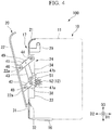
FIG. 4 is a sectional view showing an open state in the inlet opening and closing mechanism of the indoor unit according to the embodiment of the invention. -
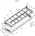
FIG. 5 is a perspective view of an inlet base and an inlet cover of the indoor unit according to the embodiment of the invention. -
FIG. 6 is a perspective view showing an assembling step of a method of assembling an indoor unit according to an embodiment of the invention. -
FIG. 7 is a perspective view showing an assembling step of the method of assembling the indoor unit according to the embodiment of the invention. -
FIG. 8 is a perspective view showing an assembling step of the method of assembling the indoor unit according to the embodiment of the invention. -
FIG. 9 is a perspective view showing an assembling step of the method of assembling the indoor unit according to the embodiment of the invention. -
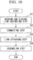
FIG. 10 is a flowchart showing a procedure of the method of assembling the indoor unit according to the embodiment of the invention. - An
air conditioner 100 includes anindoor unit 10 that is provided in a room and an outdoor unit (not shown) that is connected to theindoor unit 10 by piping and is provided outside the room. Theindoor unit 10 sucks air, performs adjustment of a temperature and humidity, and then blows out air to perform air conditioning in the room. Hereinafter, theindoor unit 10 according to an embodiment of the invention will be described. - As shown in
FIGS. 1 and 2 , theindoor unit 10 includes an air-conditioningmain body 11 in which aheat exchanger 13, ablower fan 14, and the like are disposed, an inlet opening andclosing mechanism 20 which forms asuction port 17 of air and is disposed on a front surface of the air-conditioningmain body 11, and a driving mechanism 12 (seeFIG. 3 ) which is provided in the air-conditioningmain body 11 and operates the inlet opening andclosing mechanism 20. Here, the front surface indicates a surface on a front side in a state where theindoor unit 10 is installed. - A shape of the air-conditioning
main body 11 is not particularly limited and in the embodiment, is formed in a horizontally elongated shape extending in a lateral direction D1. Ablowout port 15 is formed in a lower portion of the air-conditioningmain body 11 and aflap 16 is mounted so as to open and close theblowout port 15. - As shown in
FIGS. 3 to 5 , the inlet opening andclosing mechanism 20 includes aninlet base 21 that is fixed to the front surface of the air-conditioningmain body 11 and is a member separated from the air-conditioningmain body 11, aninlet panel 22 that is provided on a front surface of theinlet base 21, an opening andclosing link mechanism 24 that connects theinlet base 21 and theinlet panel 22, and alink case 23 that accommodates or attaches the opening andclosing link mechanism 24. - The
suction port 17 is formed on the front surface of theinlet base 21 and is formed in a substantially quadrangular plate shape. Thesuction port 17 is provided on the front surface and is formed by a plurality of throughopenings 26 partitioned in a lattice shape in upward and downward, and rightward and leftward directions. - Attaching
holes 27 are respectively provided on both end sides of theinlet base 21 in the lateral direction D1 to extend in an upward and downward direction D3. Each of the attachingholes 27 penetrates theinlet base 21 in a plate thickness direction and has a rectangular shape when viewed from the plate thickness direction. In addition, as shown inFIGS. 5 and9 , alocking claw 28 is provided as a locking portion around the attachinghole 27. Thelocking claw 28 protrudes rearward from the attachinghole 27 to the air-conditioningmain body 11. - In addition,
hinge portions 29 are provided in the upper portion of theinlet base 21 on both end sides in the lateral direction D1. As thehinge portions 29 are connected to the air-conditioningmain body 11, theinlet base 21 rotates with respect to the air-conditioningmain body 11 and the lower portion of theinlet base 21 is movable in a forward and rearward direction D2 and the upward and downward direction D3. Therefore, theinlet base 21 can largely open the front surface of the air-conditioningmain body 11. - In addition,
hook receiving portions 31 formed of through holes or the like are provided as hook portions which penetrate theinlet base 21 in the plate thickness direction and are formed in a quadrangular shape when viewed in the plate thickness direction, in the lower portion of theinlet base 21 on the both end sides in the lateral direction D1 and below the attaching holes 27. - The
inlet panel 22 is formed in a substantially quadrangular plate shape which is equal in size and shape as those of theinlet base 21, or one size larger. Theinlet panel 22 is provided so as to overlap theinlet base 21 from the outside (front surface side) of theinlet base 21. - As shown in
FIG. 3 , when theair conditioner 100 is stopped, as theinlet panel 22 close theinlet base 21, thesuction port 17 provided on the front surface of the air-conditioningmain body 11 can be in a closed state. In addition, as shown inFIG. 4 , when theair conditioner 100 is operated, thesuction port 17 can be in an open state by separating theinlet panel 22 from theinlet base 21. - Hooking hooks 32, which protrude rearward to the
inlet base 21 as hook portions that lock theinlet base 21 and theinlet panel 22 so as to be displaceable with respect to each other, are provided in the lower portion of theinlet panel 22 on the both end sides in the lateral direction D1. The hooking hooks 32 are inserted into thehook receiving portions 31 of theinlet base 21 and are hooked. Even when theinlet panel 22 is in the closed state or in the open state, a state where the hookinghooks 32 are locked to thehook receiving portions 31 is always maintained. A pair of receivingportions 22a, to which the opening andclosing link mechanism 24 is connected and which is separated from each other in the upward and downward direction D3, is provided on the both end sides of theinlet panel 22 in the lateral direction D1. The receivingportion 22a protrudes rearward from theinlet panel 22 to theinlet base 21. - The
link case 23 is a box-shaped thin member having agroove 33 which extends in the upward and downward direction and of which one side (front side) is opened. A bottom portion (bottom surface portion on aninlet base 21 side) of thegroove 33 partially penetrates and opens. In a state where thelink case 23 is accommodated in the attachinghole 27 of theinlet base 21 with the opening of thegroove 33 facing aninlet panel 22 side, and a part of thelink case 23 protrudes on theinlet base 21 side, thelink case 23 is attached and fixed to theinlet base 21. - In addition, a
flange 36 is provided at an opening end of thelink case 23 and when thelink case 23 is accommodated in the attachinghole 27, theflange 36 can abut against the surface of theinlet base 21 so as to be positioned. Furthermore, lockingholes 37 as the locking portions which lock thelink case 23 and theinlet base 21 to each other are provided on a side surface in thelink case 23 by locking the lockingclaws 28 provided in the attachingholes 27 of theinlet base 21 to thelink case 23. - As shown in
FIGS. 3 ,4 , and6 to 9 , the opening andclosing link mechanism 24 includes aslide rail 34 that is provided in thelink case 23, aslider 38 that is slidably mounted on theslide rail 34, and anupper link 41, alower link 42, and anintermediate link 43 which are connected to thelink case 23 or theslider 38. - The
slide rail 34 is provided to extend in the upward and downward direction D3 along the bottom surface of thegroove 33 of thelink case 23. - The
slider 38 is supported by theslide rail 34 and is attached to thelink case 23 so as to be slidable in the upward and downward direction D3. In addition, in the embodiment, theslider 38 has arack gear 51 facing the air-conditioningmain body 11 side. - The
upper link 41 has a bar shape. Both ends of theupper link 41 are respectively connected to a fixedpivot portion 44 provided above theslide rail 34 of thelink case 23 and anupper pivot portion 46 of the receivingportion 22a provided in theinlet panel 22 so as to rotate around an axis extending in the lateral direction D1. - The
lower link 42 has a bar shape similar to theupper link 41. Both ends of thelower link 42 are respectively connected to amovable pivot portion 47a provided in theslider 38 and alower pivot portion 48 of the receivingportion 22a provided below theupper pivot portion 46 of theinlet panel 22 so as to rotate around the axis extending in the lateral direction D1. Thelower link 42 is formed to be shorter than theupper link 41. - The
intermediate link 43 has a bar shape similar to theupper link 41 and thelower link 42. Both ends of theintermediate link 43 are respectively connected to amovable pivot portion 47b provided in theslider 38 and adjacent above themovable pivot portion 47a, and anintermediate pivot portion 49 provided at an intermediate position of theupper link 41 so as to rotate around the axis extending in the lateral direction D1. - The
driving mechanism 12 is provided on the air-conditioningmain body 11 side and slidably moves theslider 38 with respect to theslide rail 34. Thedriving mechanism 12 includes apinion gear 52 provided so as to mesh with therack gear 51 of theslider 38 and a driving source such as a motor (not shown) that drives thepinion gear 52 to rotate. - As shown in
FIGS. 3 and4 , in the opening andclosing link mechanism 24, as thepinion gear 52 is rotated by thedriving mechanism 12, theslider 38 is slidably moved upward with respect to thelink case 23 and pushes up theintermediate link 43. Then, in theupper pivot portion 46, theupper link 41 lifts the upper portion of theinlet panel 22 while rotating with respect to theinlet panel 22 and separates theinlet panel 22 forward from thesuction port 17. - At the same time, the
lower link 42 is also moved upward by the movement of theslider 38 upward. In this case, theinlet panel 22 lifts while the lower portion of theinlet panel 22 is pulled in a direction closing theinlet base 21. Therefore, thesuction port 17 of the air-conditioningmain body 11 is in the open state. - On the other hand, as the
pinion gear 52 is rotated in the reverse direction and theslider 38 is moved downward, thesuction port 17 of the air-conditioningmain body 11 is in the closed state by operating each of thelinks inlet panel 22 in a direction opposite to the above description. In the closed state, each of thelinks groove 33 of thelink case 23. - Here, it is possible to appropriately set a lifting amount and an inclination angle of the
inlet panel 22 with respect to theinlet base 21 by appropriately setting a moving amount of theslider 38 and the position and the length of each of thelinks - A method of assembling the
indoor unit 10 by assembling the inlet opening andclosing mechanism 20 to the air-conditioningmain body 11 which is preliminarily manufactured will be described with reference toFIGS. 6 to 10 . First an opening and closing link assembling step S1 is executed. In the opening and closing link assembling step S1, as shown inFIG. 6 , one end side of thelower link 42 and theintermediate link 43 is connected to themovable pivot portions slider 38. Thereafter, theslider 38 is mounted on theslide rail 34 of thelink case 23, and theintermediate link 43 and thelower link 42 are inserted into the bottom portion of thegroove 33 of thelink case 23 so as to be disposed to extend to the opening side of thegroove 33. - As shown in
FIG. 7 , one end side of theupper link 41 is connected to the fixedpivot portion 44 of thelink case 23. In addition, the other end side of theintermediate link 43 connected to theslider 38 is connected to theintermediate pivot portion 49 of theupper link 41. - Thereafter, a connecting step S2 is executed. That is, as shown in
FIG. 8 , theupper link 41 and thelower link 42 connected to thelink case 23 or theslider 38 are respectively connected to theupper pivot portion 46 and thelower pivot portion 48 of theinlet panel 22. As described above, first, the opening andclosing link mechanism 24 which is accommodated in or attached to thelink case 23 is connected to theinlet panel 22 so as to rotate. - Thereafter, a link attaching step S3 is executed. That is, as shown in
FIG. 9 , theinlet base 21 and theinlet panel 22 are overlapped, the hookinghook 32 of theinlet panel 22 is inserted into thehook receiving portion 31 of theinlet base 21 to be positioned, and thelink case 23 is inserted into the attachinghole 27 of theinlet base 21. Theflange 36 of thelink case 23 abuts against the surface of theinlet base 21. Furthermore, thelink case 23 is attached and fixed to theinlet base 21 by locking the lockingclaw 28 provided in the attachinghole 27 to the lockinghole 37 of thelink case 23. - Finally, an assembling step S4 is executed. That is, in a state where the
inlet panel 22 and theinlet base 21 connected by the opening andclosing link mechanism 24 and thelink case 23 are overlapped, theinlet base 21 is connected to the air-conditioningmain body 11 by thehinge portion 29, and thepinion gear 52 is meshed with therack gear 51 to assemble theinlet base 21 to the air-conditioningmain body 11. - According to the
indoor unit 10 and the method of assembling thereof of the embodiment described above, the opening andclosing link mechanism 24, which is accommodated in or attached to thelink case 23, is connected to theinlet panel 22 in advance and the opening andclosing link mechanism 24 can be attached to theinlet base 21 together with thelink case 23. In addition, thereafter, theinlet panel 22, the opening andclosing link mechanism 24, and theinlet base 21 can be integrally assembled to the air-conditioningmain body 11. - Therefore, when the
inlet panel 22 is assembled to the air-conditioningmain body 11, an operation of connecting the opening andclosing link mechanism 24 may not be performed. That is, it is not necessary to perform an operation such as inserting a tool or the hand into a narrow gap between theinlet panel 22 and the air-conditioningmain body 11 to connect the opening andclosing link mechanism 24 to theinlet panel 22. Therefore, theinlet panel 22 that covers thesuction port 17 so as to be openable and closable can be easily assembled to the air-conditioningmain body 11, which leads to an improvement of workability. - In addition, in the
indoor unit 10 of the embodiment, the lockingclaw 28 and the lockinghole 37 for locking thelink case 23 and theinlet base 21 are provided. Therefore, it is possible to easily attach and fix thelink case 23 to theinlet base 21 and it is possible to further easily assemble the opening andclosing link mechanism 24 to the air-conditioningmain body 11 via theinlet base 21. - In addition, in the embodiment, a driving force from the
driving mechanism 12 is transmitted to theinlet panel 22 by theupper link 41, theintermediate link 43, and thelower link 42 via theslider 38 having therack gear 51 mounted on theslide rail 34. - Therefore, the
intermediate link 43 and theupper link 41 are rotated by moving theslider 38 upward and thereby the upper portion of theinlet panel 22 can be separated from thesuction port 17 to the outside to be lifted. In this case, the lower portion of theinlet panel 22 is not largely separated from the air-conditioningmain body 11 by thelower link 42. Therefore, in a state where only the upper portion of theinlet panel 22 is separated from the air-conditioningmain body 11 and is inclined with respect to the air-conditioningmain body 11, it is possible to obliquely and largely open and close thesuction port 17 of the air-conditioningmain body 11 at the upper portion. - In the
indoor unit 10 of the embodiment, theinlet base 21 and theinlet panel 22 are always locked to each other by thehook receiving portion 31 and the hookinghook 32 so as to be displaceable. Therefore, it is possible to support the load of theinlet panel 22 by theinlet base 21 via thehook receiving portion 31 and the hookinghook 32. Therefore, a burden of the load from theinlet panel 22 to the opening andclosing link mechanism 24 can be reduced, theinlet panel 22 can be smoothly and easily operated, and the durability of thelink mechanism 24 can be easily secured. - Furthermore, when the opening and
closing link mechanism 24 and thelink case 23 which are connected to theinlet panel 22 in advance are attached to theinlet base 21, thehook receiving portion 31 and the hookinghook 32 can play a role of positioning. Therefore, the assembly of theindoor unit 10 can be further facilitated. - Above, although the embodiment of the invention is described in detail above, it is possible to make some design changes within a range not departing from the technical idea of the invention. For example, in the embodiment, the configuration of the opening and
closing link mechanism 24 may use another link mechanism as long as the operation capable of opening and closing thesuction port 17 by theinlet panel 22 is obtained by theinlet panel 22. For example, although theslider 38 is driven by therack gear 51 and thepinion gear 52, if theslider 38 can slide along theslide rail 34, theslider 38 may be driven by another driving mechanism. In addition, instead of the mechanism of the rack and pinion, a mechanism having a cylinder may be used. - In addition, the
inlet panel 22 is not limited to covering the entire front surface of the air-conditioningmain body 11 and may be provided at another position such as the upper surface. Furthermore, the opening and closing direction of theinlet panel 22 is not limited to the above-described case and the opening and closing direction may be set according to the shape and the position of thesuction port 17. - In the above description, the
inlet base 21 and theinlet panel 22 have the same contour as the front surface of the air-conditioningmain body 11, but may have a shape different from the front surface of the air-conditioningmain body 11. - In addition, contrary to the above case, the
hook receiving portion 31 may be provided in theinlet panel 22 and the hookinghook 32 may be provided in theinlet base 21. - While preferred embodiments of the invention have been described and shown above, it should be understood that these are exemplary of the invention and are not to be considered as limiting. Additions, omissions, substitutions, and other modifications can be made without departing from the scope of the present invention. Accordingly, the invention is not to be considered as being limited by the foregoing description, and is only limited by the scope of the appended claims.
-
- D1
- lateral direction
- D2
- forward and rearward direction
- D3
- upward and downward direction
- 10
- indoor unit
- 11
- air-conditioning main body
- 12
- driving mechanism
- 13
- heat exchanger
- 14
- blower fan
- 15
- blowout port
- 16
- flap
- 17
- suction port
- 20
- inlet opening and closing mechanism
- 21
- inlet base
- 22
- inlet panel
- 22a
- receiving portion
- 23
- link case
- 24
- opening and closing link mechanism
- 26
- through opening
- 27
- attaching hole
- 28
- locking claw (locking portion)
- 29
- hinge portion
- 31
- hook receiving portion (hook portion)
- 32
- hooking hook (hook portion)
- 33
- groove
- 34
- slide rail
- 36
- flange
- 37
- locking hole (locking portion)
- 38
- slider
- 41
- upper link
- 42
- lower link
- 43
- intermediate link
- 44
- fixed pivot portion
- 46
- upper pivot portion
- 47a, 47b
- movable pivot portion
- 48
- lower pivot portion
- 49
- intermediate pivot portion
- 51
- rack gear
- 52
- pinion gear
- 100
- air conditioner
- S1
- opening and closing link assembling step
- S2
- connecting step
- S3
- link attaching step
- S4
- assembling step
Claims (5)
- An indoor unit (10) of an air conditioner (100), comprising:an air-conditioning main body (11);an inlet base (21) that is provided on a front surface of the air-conditioning main body (11) to form a suction port (17) of air and is a member separate from the air-conditioning main body (11);an inlet panel (22) that is provided on a front surface of the inlet base (21) to cover the suction port (17);an opening and closing link mechanism (24) that connects the inlet base (21) and the inlet panel (22) to each other to allow the suction port (17) to be openable and closable by the inlet panel (22);a link case (23) that is capable of attaching to the inlet base (21) in a state where the opening and closing link mechanism (24) is accommodated in or attached to the link case (23), and the opening and closing link mechanism (24) is connected to the inlet panel (22); anda driving mechanism (12) that is provided in the air-conditioning main body (11) to operate the link mechanism (24).
- The indoor unit (10) of an air conditioner (100) according to claim 1,
wherein locking portions that lock and fix the link case (23) and the inlet base (21) to each other are provided in the link case (23) and the inlet base (21). - The indoor unit (10) of an air conditioner (100) according to claim 1 or 2,
wherein the opening and closing link mechanism (24) includes a slide rail (34) that is provided in the link case (23) so as to extend in an upward and downward direction (D3),
a slider (38) that is slidably mounted on the slide rail (34),
an upper link (41) that is connected to the inlet panel (22) and the link case (23) so as to rotate in the upward and downward direction (D3),
a lower link (42) that is disposed below the upper link (41) and is connected to the slider (38) and the inlet panel (22) so as to rotate in the upward and downward direction (D3), and
an intermediate link (43) that is connected to the slider (38) and an intermediate position of the upper link (41) so as to rotate in the upward and downward direction (D3), and
wherein the driving mechanism (12) is capable of moving the slider (38) in the upward and downward direction (D3). - The indoor unit (10) of an air conditioner (100) according to any one of claims 1 to 3,
wherein hook portions (31, 32), which are always locked to each other so as to be displaceable, are provided in the inlet base (21) and the inlet panel (22). - A method of assembling the indoor unit (10) of an air conditioner (100) according to any one of claims 1 to 4, the method comprising:a connecting step (S2) of connecting the opening and closing link mechanism (24) to the inlet panel (22);a link attaching step (S3) of overlapping the inlet base (21) and the inlet panel (22) and thereby attaching the link case (23) to the inlet base (21) after the connecting step (S2); andan assembling step (S4) of assembling the inlet base (21) and the inlet panel (22) to the air-conditioning main body (11) after the link attaching step (S3).
Applications Claiming Priority (1)
| Application Number | Priority Date | Filing Date | Title |
|---|---|---|---|
| JP2016232896A JP2018091506A (en) | 2016-11-30 | 2016-11-30 | Indoor unit for air conditioner and method for assembling indoor unit for air conditioner |
Publications (2)
| Publication Number | Publication Date |
|---|---|
| EP3330630A1 true EP3330630A1 (en) | 2018-06-06 |
| EP3330630B1 EP3330630B1 (en) | 2019-05-29 |
Family
ID=60515252
Family Applications (1)
| Application Number | Title | Priority Date | Filing Date |
|---|---|---|---|
| EP17204522.1A Active EP3330630B1 (en) | 2016-11-30 | 2017-11-29 | Method of assembling indoor unit of air conditioner |
Country Status (4)
| Country | Link |
|---|---|
| EP (1) | EP3330630B1 (en) |
| JP (1) | JP2018091506A (en) |
| AU (1) | AU2017268563B2 (en) |
| ES (1) | ES2732017T3 (en) |
Cited By (6)
| Publication number | Priority date | Publication date | Assignee | Title |
|---|---|---|---|---|
| CN108954534A (en) * | 2018-08-24 | 2018-12-07 | 珠海格力电器股份有限公司 | Panel clamping structure, indoor unit and air conditioning system |
| US10422549B2 (en) * | 2014-04-24 | 2019-09-24 | Gree Electric Appliances, Inc. Of Zhuhai | Movement mechanism, panel mechanism and household appliance |
| US20210010713A1 (en) * | 2018-05-16 | 2021-01-14 | Mitsubishi Electric Corporation | Indoor unit of air-conditioning apparatus and air-conditioning apparatus |
| CN114206047A (en) * | 2018-10-05 | 2022-03-18 | 大金研发马来西亚私人有限公司 | Shell with hinge type access panel |
| CN114427701A (en) * | 2020-10-29 | 2022-05-03 | 宁波奥克斯电气股份有限公司 | Air conditioner indoor unit and air conditioner |
| US11867425B2 (en) * | 2020-01-10 | 2024-01-09 | Samsung Electronics Co., Ltd. | Air conditioner |
Families Citing this family (1)
| Publication number | Priority date | Publication date | Assignee | Title |
|---|---|---|---|---|
| KR102229473B1 (en) * | 2019-03-18 | 2021-03-18 | 엘지전자 주식회사 | Indoor unit for air conditioner |
Citations (5)
| Publication number | Priority date | Publication date | Assignee | Title |
|---|---|---|---|---|
| EP1271065A2 (en) * | 2001-06-19 | 2003-01-02 | Lg Electronics Inc. | Air conditioner |
| US20060032198A1 (en) * | 2004-08-16 | 2006-02-16 | Lg Electronics Inc. | Filter unit of air conditioner |
| EP1681516A1 (en) * | 2003-09-30 | 2006-07-19 | Daikin Industries, Ltd. | Indoor unit of air conditioner |
| JP2008267777A (en) | 2007-04-19 | 2008-11-06 | Samsung Electronics Co Ltd | Air conditioner |
| EP2184551A2 (en) * | 2008-11-10 | 2010-05-12 | LG Electronics Inc. | Indoor unit of air conditioner |
Family Cites Families (2)
| Publication number | Priority date | Publication date | Assignee | Title |
|---|---|---|---|---|
| JP4624174B2 (en) * | 2004-08-27 | 2011-02-02 | 三洋電機株式会社 | Air conditioner |
| JP4589133B2 (en) * | 2005-01-26 | 2010-12-01 | 東芝キヤリア株式会社 | Movable panel opening / closing mechanism |
-
2016
- 2016-11-30 JP JP2016232896A patent/JP2018091506A/en active Pending
-
2017
- 2017-11-29 ES ES17204522T patent/ES2732017T3/en active Active
- 2017-11-29 EP EP17204522.1A patent/EP3330630B1/en active Active
- 2017-11-29 AU AU2017268563A patent/AU2017268563B2/en active Active
Patent Citations (5)
| Publication number | Priority date | Publication date | Assignee | Title |
|---|---|---|---|---|
| EP1271065A2 (en) * | 2001-06-19 | 2003-01-02 | Lg Electronics Inc. | Air conditioner |
| EP1681516A1 (en) * | 2003-09-30 | 2006-07-19 | Daikin Industries, Ltd. | Indoor unit of air conditioner |
| US20060032198A1 (en) * | 2004-08-16 | 2006-02-16 | Lg Electronics Inc. | Filter unit of air conditioner |
| JP2008267777A (en) | 2007-04-19 | 2008-11-06 | Samsung Electronics Co Ltd | Air conditioner |
| EP2184551A2 (en) * | 2008-11-10 | 2010-05-12 | LG Electronics Inc. | Indoor unit of air conditioner |
Cited By (8)
| Publication number | Priority date | Publication date | Assignee | Title |
|---|---|---|---|---|
| US10422549B2 (en) * | 2014-04-24 | 2019-09-24 | Gree Electric Appliances, Inc. Of Zhuhai | Movement mechanism, panel mechanism and household appliance |
| US20210010713A1 (en) * | 2018-05-16 | 2021-01-14 | Mitsubishi Electric Corporation | Indoor unit of air-conditioning apparatus and air-conditioning apparatus |
| US11906195B2 (en) * | 2018-05-16 | 2024-02-20 | Mitsubishi Electric Corporation | Indoor unit of air-conditioning apparatus and air-conditioning apparatus |
| CN108954534A (en) * | 2018-08-24 | 2018-12-07 | 珠海格力电器股份有限公司 | Panel clamping structure, indoor unit and air conditioning system |
| CN114206047A (en) * | 2018-10-05 | 2022-03-18 | 大金研发马来西亚私人有限公司 | Shell with hinge type access panel |
| CN114206047B (en) * | 2018-10-05 | 2024-05-10 | 大金研发马来西亚私人有限公司 | Shell with hinge type access panel |
| US11867425B2 (en) * | 2020-01-10 | 2024-01-09 | Samsung Electronics Co., Ltd. | Air conditioner |
| CN114427701A (en) * | 2020-10-29 | 2022-05-03 | 宁波奥克斯电气股份有限公司 | Air conditioner indoor unit and air conditioner |
Also Published As
| Publication number | Publication date |
|---|---|
| AU2017268563A1 (en) | 2018-06-14 |
| JP2018091506A (en) | 2018-06-14 |
| AU2017268563B2 (en) | 2018-12-06 |
| ES2732017T3 (en) | 2019-11-20 |
| EP3330630B1 (en) | 2019-05-29 |
Similar Documents
| Publication | Publication Date | Title |
|---|---|---|
| EP3330630B1 (en) | Method of assembling indoor unit of air conditioner | |
| JP4335937B2 (en) | Air conditioner | |
| JP6359577B2 (en) | Air conditioner | |
| EP3774526B1 (en) | Door assembly comprising hinge with two pins | |
| EP2202468B1 (en) | Air conditioning apparatus | |
| EP2752625B1 (en) | Air conditioner | |
| JP6359919B2 (en) | Air conditioner | |
| JP4237238B1 (en) | Air conditioner | |
| KR20100073121A (en) | Ceiling type air conditioner | |
| JPWO2019038798A1 (en) | Ceiling embedded air conditioner | |
| KR20090047066A (en) | Air conditioner | |
| JP4283322B2 (en) | Air conditioner | |
| KR102147697B1 (en) | Fitting of an at least liftable, but preferably also displaceable wing of windows or doors | |
| WO2014041891A1 (en) | Air conditioner | |
| JP2011080616A (en) | Air conditioner | |
| JP2002096764A (en) | Power unit structure of work machine | |
| JP6538374B2 (en) | Air conditioner | |
| US7325359B2 (en) | Projection window operator | |
| KR20120106434A (en) | Apparatus for automatically opening and closing a window | |
| EP1331349A2 (en) | Sash system having doors being openable and closable by sliding and folding | |
| JP2009063257A (en) | Air conditioner | |
| JP2010019497A (en) | Air conditioner | |
| JP6680976B2 (en) | Window opening / closing device and opening / closing window | |
| KR102327726B1 (en) | Automatically open/close ventilation window structure for manual use | |
| KR20220026249A (en) | louver for driving handle body |
Legal Events
| Date | Code | Title | Description |
|---|---|---|---|
| PUAI | Public reference made under article 153(3) epc to a published international application that has entered the european phase |
Free format text: ORIGINAL CODE: 0009012 |
|
| STAA | Information on the status of an ep patent application or granted ep patent |
Free format text: STATUS: THE APPLICATION HAS BEEN PUBLISHED |
|
| AK | Designated contracting states |
Kind code of ref document: A1 Designated state(s): AL AT BE BG CH CY CZ DE DK EE ES FI FR GB GR HR HU IE IS IT LI LT LU LV MC MK MT NL NO PL PT RO RS SE SI SK SM TR |
|
| AX | Request for extension of the european patent |
Extension state: BA ME |
|
| STAA | Information on the status of an ep patent application or granted ep patent |
Free format text: STATUS: REQUEST FOR EXAMINATION WAS MADE |
|
| 17P | Request for examination filed |
Effective date: 20181206 |
|
| RBV | Designated contracting states (corrected) |
Designated state(s): AL AT BE BG CH CY CZ DE DK EE ES FI FR GB GR HR HU IE IS IT LI LT LU LV MC MK MT NL NO PL PT RO RS SE SI SK SM TR |
|
| GRAP | Despatch of communication of intention to grant a patent |
Free format text: ORIGINAL CODE: EPIDOSNIGR1 |
|
| STAA | Information on the status of an ep patent application or granted ep patent |
Free format text: STATUS: GRANT OF PATENT IS INTENDED |
|
| RIC1 | Information provided on ipc code assigned before grant |
Ipc: F24F 1/00 20190101ALI20190121BHEP Ipc: F24F 13/14 20060101AFI20190121BHEP Ipc: F24F 13/20 20060101ALI20190121BHEP |
|
| INTG | Intention to grant announced |
Effective date: 20190219 |
|
| GRAS | Grant fee paid |
Free format text: ORIGINAL CODE: EPIDOSNIGR3 |
|
| GRAA | (expected) grant |
Free format text: ORIGINAL CODE: 0009210 |
|
| STAA | Information on the status of an ep patent application or granted ep patent |
Free format text: STATUS: THE PATENT HAS BEEN GRANTED |
|
| AK | Designated contracting states |
Kind code of ref document: B1 Designated state(s): AL AT BE BG CH CY CZ DE DK EE ES FI FR GB GR HR HU IE IS IT LI LT LU LV MC MK MT NL NO PL PT RO RS SE SI SK SM TR |
|
| REG | Reference to a national code |
Ref country code: GB Ref legal event code: FG4D |
|
| REG | Reference to a national code |
Ref country code: CH Ref legal event code: EP |
|
| REG | Reference to a national code |
Ref country code: AT Ref legal event code: REF Ref document number: 1138495 Country of ref document: AT Kind code of ref document: T Effective date: 20190615 |
|
| REG | Reference to a national code |
Ref country code: DE Ref legal event code: R096 Ref document number: 602017004216 Country of ref document: DE |
|
| REG | Reference to a national code |
Ref country code: IE Ref legal event code: FG4D |
|
| REG | Reference to a national code |
Ref country code: NL Ref legal event code: MP Effective date: 20190529 |
|
| REG | Reference to a national code |
Ref country code: LT Ref legal event code: MG4D |
|
| PG25 | Lapsed in a contracting state [announced via postgrant information from national office to epo] |
Ref country code: PT Free format text: LAPSE BECAUSE OF FAILURE TO SUBMIT A TRANSLATION OF THE DESCRIPTION OR TO PAY THE FEE WITHIN THE PRESCRIBED TIME-LIMIT Effective date: 20190930 Ref country code: LT Free format text: LAPSE BECAUSE OF FAILURE TO SUBMIT A TRANSLATION OF THE DESCRIPTION OR TO PAY THE FEE WITHIN THE PRESCRIBED TIME-LIMIT Effective date: 20190529 Ref country code: HR Free format text: LAPSE BECAUSE OF FAILURE TO SUBMIT A TRANSLATION OF THE DESCRIPTION OR TO PAY THE FEE WITHIN THE PRESCRIBED TIME-LIMIT Effective date: 20190529 Ref country code: FI Free format text: LAPSE BECAUSE OF FAILURE TO SUBMIT A TRANSLATION OF THE DESCRIPTION OR TO PAY THE FEE WITHIN THE PRESCRIBED TIME-LIMIT Effective date: 20190529 Ref country code: NO Free format text: LAPSE BECAUSE OF FAILURE TO SUBMIT A TRANSLATION OF THE DESCRIPTION OR TO PAY THE FEE WITHIN THE PRESCRIBED TIME-LIMIT Effective date: 20190829 Ref country code: AL Free format text: LAPSE BECAUSE OF FAILURE TO SUBMIT A TRANSLATION OF THE DESCRIPTION OR TO PAY THE FEE WITHIN THE PRESCRIBED TIME-LIMIT Effective date: 20190529 Ref country code: SE Free format text: LAPSE BECAUSE OF FAILURE TO SUBMIT A TRANSLATION OF THE DESCRIPTION OR TO PAY THE FEE WITHIN THE PRESCRIBED TIME-LIMIT Effective date: 20190529 |
|
| REG | Reference to a national code |
Ref country code: ES Ref legal event code: FG2A Ref document number: 2732017 Country of ref document: ES Kind code of ref document: T3 Effective date: 20191120 |
|
| PG25 | Lapsed in a contracting state [announced via postgrant information from national office to epo] |
Ref country code: LV Free format text: LAPSE BECAUSE OF FAILURE TO SUBMIT A TRANSLATION OF THE DESCRIPTION OR TO PAY THE FEE WITHIN THE PRESCRIBED TIME-LIMIT Effective date: 20190529 Ref country code: RS Free format text: LAPSE BECAUSE OF FAILURE TO SUBMIT A TRANSLATION OF THE DESCRIPTION OR TO PAY THE FEE WITHIN THE PRESCRIBED TIME-LIMIT Effective date: 20190529 Ref country code: GR Free format text: LAPSE BECAUSE OF FAILURE TO SUBMIT A TRANSLATION OF THE DESCRIPTION OR TO PAY THE FEE WITHIN THE PRESCRIBED TIME-LIMIT Effective date: 20190830 Ref country code: BG Free format text: LAPSE BECAUSE OF FAILURE TO SUBMIT A TRANSLATION OF THE DESCRIPTION OR TO PAY THE FEE WITHIN THE PRESCRIBED TIME-LIMIT Effective date: 20190829 |
|
| REG | Reference to a national code |
Ref country code: AT Ref legal event code: MK05 Ref document number: 1138495 Country of ref document: AT Kind code of ref document: T Effective date: 20190529 |
|
| PG25 | Lapsed in a contracting state [announced via postgrant information from national office to epo] |
Ref country code: CZ Free format text: LAPSE BECAUSE OF FAILURE TO SUBMIT A TRANSLATION OF THE DESCRIPTION OR TO PAY THE FEE WITHIN THE PRESCRIBED TIME-LIMIT Effective date: 20190529 Ref country code: RO Free format text: LAPSE BECAUSE OF FAILURE TO SUBMIT A TRANSLATION OF THE DESCRIPTION OR TO PAY THE FEE WITHIN THE PRESCRIBED TIME-LIMIT Effective date: 20190529 Ref country code: NL Free format text: LAPSE BECAUSE OF FAILURE TO SUBMIT A TRANSLATION OF THE DESCRIPTION OR TO PAY THE FEE WITHIN THE PRESCRIBED TIME-LIMIT Effective date: 20190529 Ref country code: EE Free format text: LAPSE BECAUSE OF FAILURE TO SUBMIT A TRANSLATION OF THE DESCRIPTION OR TO PAY THE FEE WITHIN THE PRESCRIBED TIME-LIMIT Effective date: 20190529 Ref country code: SK Free format text: LAPSE BECAUSE OF FAILURE TO SUBMIT A TRANSLATION OF THE DESCRIPTION OR TO PAY THE FEE WITHIN THE PRESCRIBED TIME-LIMIT Effective date: 20190529 Ref country code: DK Free format text: LAPSE BECAUSE OF FAILURE TO SUBMIT A TRANSLATION OF THE DESCRIPTION OR TO PAY THE FEE WITHIN THE PRESCRIBED TIME-LIMIT Effective date: 20190529 Ref country code: AT Free format text: LAPSE BECAUSE OF FAILURE TO SUBMIT A TRANSLATION OF THE DESCRIPTION OR TO PAY THE FEE WITHIN THE PRESCRIBED TIME-LIMIT Effective date: 20190529 |
|
| PG25 | Lapsed in a contracting state [announced via postgrant information from national office to epo] |
Ref country code: SM Free format text: LAPSE BECAUSE OF FAILURE TO SUBMIT A TRANSLATION OF THE DESCRIPTION OR TO PAY THE FEE WITHIN THE PRESCRIBED TIME-LIMIT Effective date: 20190529 |
|
| REG | Reference to a national code |
Ref country code: DE Ref legal event code: R097 Ref document number: 602017004216 Country of ref document: DE |
|
| PG25 | Lapsed in a contracting state [announced via postgrant information from national office to epo] |
Ref country code: TR Free format text: LAPSE BECAUSE OF FAILURE TO SUBMIT A TRANSLATION OF THE DESCRIPTION OR TO PAY THE FEE WITHIN THE PRESCRIBED TIME-LIMIT Effective date: 20190529 |
|
| PLBE | No opposition filed within time limit |
Free format text: ORIGINAL CODE: 0009261 |
|
| STAA | Information on the status of an ep patent application or granted ep patent |
Free format text: STATUS: NO OPPOSITION FILED WITHIN TIME LIMIT |
|
| PG25 | Lapsed in a contracting state [announced via postgrant information from national office to epo] |
Ref country code: PL Free format text: LAPSE BECAUSE OF FAILURE TO SUBMIT A TRANSLATION OF THE DESCRIPTION OR TO PAY THE FEE WITHIN THE PRESCRIBED TIME-LIMIT Effective date: 20190529 |
|
| 26N | No opposition filed |
Effective date: 20200303 |
|
| PG25 | Lapsed in a contracting state [announced via postgrant information from national office to epo] |
Ref country code: SI Free format text: LAPSE BECAUSE OF FAILURE TO SUBMIT A TRANSLATION OF THE DESCRIPTION OR TO PAY THE FEE WITHIN THE PRESCRIBED TIME-LIMIT Effective date: 20190529 |
|
| PG25 | Lapsed in a contracting state [announced via postgrant information from national office to epo] |
Ref country code: MC Free format text: LAPSE BECAUSE OF FAILURE TO SUBMIT A TRANSLATION OF THE DESCRIPTION OR TO PAY THE FEE WITHIN THE PRESCRIBED TIME-LIMIT Effective date: 20190529 Ref country code: LU Free format text: LAPSE BECAUSE OF NON-PAYMENT OF DUE FEES Effective date: 20191129 |
|
| REG | Reference to a national code |
Ref country code: BE Ref legal event code: MM Effective date: 20191130 |
|
| PG25 | Lapsed in a contracting state [announced via postgrant information from national office to epo] |
Ref country code: FR Free format text: LAPSE BECAUSE OF NON-PAYMENT OF DUE FEES Effective date: 20191130 Ref country code: IE Free format text: LAPSE BECAUSE OF NON-PAYMENT OF DUE FEES Effective date: 20191129 |
|
| PG25 | Lapsed in a contracting state [announced via postgrant information from national office to epo] |
Ref country code: BE Free format text: LAPSE BECAUSE OF NON-PAYMENT OF DUE FEES Effective date: 20191130 |
|
| PG25 | Lapsed in a contracting state [announced via postgrant information from national office to epo] |
Ref country code: CY Free format text: LAPSE BECAUSE OF FAILURE TO SUBMIT A TRANSLATION OF THE DESCRIPTION OR TO PAY THE FEE WITHIN THE PRESCRIBED TIME-LIMIT Effective date: 20190529 |
|
| PG25 | Lapsed in a contracting state [announced via postgrant information from national office to epo] |
Ref country code: IS Free format text: LAPSE BECAUSE OF FAILURE TO SUBMIT A TRANSLATION OF THE DESCRIPTION OR TO PAY THE FEE WITHIN THE PRESCRIBED TIME-LIMIT Effective date: 20190929 |
|
| REG | Reference to a national code |
Ref country code: CH Ref legal event code: PL |
|
| PG25 | Lapsed in a contracting state [announced via postgrant information from national office to epo] |
Ref country code: HU Free format text: LAPSE BECAUSE OF FAILURE TO SUBMIT A TRANSLATION OF THE DESCRIPTION OR TO PAY THE FEE WITHIN THE PRESCRIBED TIME-LIMIT; INVALID AB INITIO Effective date: 20171129 Ref country code: MT Free format text: LAPSE BECAUSE OF FAILURE TO SUBMIT A TRANSLATION OF THE DESCRIPTION OR TO PAY THE FEE WITHIN THE PRESCRIBED TIME-LIMIT Effective date: 20190529 |
|
| PG25 | Lapsed in a contracting state [announced via postgrant information from national office to epo] |
Ref country code: CH Free format text: LAPSE BECAUSE OF NON-PAYMENT OF DUE FEES Effective date: 20201130 Ref country code: LI Free format text: LAPSE BECAUSE OF NON-PAYMENT OF DUE FEES Effective date: 20201130 |
|
| PG25 | Lapsed in a contracting state [announced via postgrant information from national office to epo] |
Ref country code: MK Free format text: LAPSE BECAUSE OF FAILURE TO SUBMIT A TRANSLATION OF THE DESCRIPTION OR TO PAY THE FEE WITHIN THE PRESCRIBED TIME-LIMIT Effective date: 20190529 |
|
| GBPC | Gb: european patent ceased through non-payment of renewal fee |
Effective date: 20211129 |
|
| PG25 | Lapsed in a contracting state [announced via postgrant information from national office to epo] |
Ref country code: GB Free format text: LAPSE BECAUSE OF NON-PAYMENT OF DUE FEES Effective date: 20211129 |
|
| REG | Reference to a national code |
Ref country code: DE Ref legal event code: R082 Ref document number: 602017004216 Country of ref document: DE Representative=s name: CBDL PATENTANWAELTE GBR, DE Ref country code: DE Ref legal event code: R082 Ref document number: 602017004216 Country of ref document: DE Representative=s name: CBDL PATENTANWAELTE EGBR, DE |
|
| PGFP | Annual fee paid to national office [announced via postgrant information from national office to epo] |
Ref country code: DE Payment date: 20250930 Year of fee payment: 9 |
|
| PGFP | Annual fee paid to national office [announced via postgrant information from national office to epo] |
Ref country code: IT Payment date: 20251022 Year of fee payment: 9 |
|
| PGFP | Annual fee paid to national office [announced via postgrant information from national office to epo] |
Ref country code: ES Payment date: 20251209 Year of fee payment: 9 |