EP3330520A1 - Method and system for protecting a turbocharger compressor wheel - Google Patents
Method and system for protecting a turbocharger compressor wheel Download PDFInfo
- Publication number
- EP3330520A1 EP3330520A1 EP17191614.1A EP17191614A EP3330520A1 EP 3330520 A1 EP3330520 A1 EP 3330520A1 EP 17191614 A EP17191614 A EP 17191614A EP 3330520 A1 EP3330520 A1 EP 3330520A1
- Authority
- EP
- European Patent Office
- Prior art keywords
- temperature
- wheel
- motor
- engine
- duration
- Prior art date
- Legal status (The legal status is an assumption and is not a legal conclusion. Google has not performed a legal analysis and makes no representation as to the accuracy of the status listed.)
- Granted
Links
- 238000000034 method Methods 0.000 title claims abstract description 47
- 230000002401 inhibitory effect Effects 0.000 claims abstract description 5
- 238000012545 processing Methods 0.000 claims description 31
- 230000005764 inhibitory process Effects 0.000 claims description 19
- 230000008569 process Effects 0.000 claims description 16
- 238000004590 computer program Methods 0.000 claims description 5
- 230000008929 regeneration Effects 0.000 claims description 5
- 238000011069 regeneration method Methods 0.000 claims description 5
- 239000007789 gas Substances 0.000 description 10
- 241000135309 Processus Species 0.000 description 6
- 230000006870 function Effects 0.000 description 5
- 238000011144 upstream manufacturing Methods 0.000 description 5
- 238000003754 machining Methods 0.000 description 4
- 239000007858 starting material Substances 0.000 description 4
- 238000004364 calculation method Methods 0.000 description 3
- 238000012986 modification Methods 0.000 description 3
- 230000004048 modification Effects 0.000 description 3
- 239000003570 air Substances 0.000 description 2
- 230000008901 benefit Effects 0.000 description 2
- 230000000694 effects Effects 0.000 description 2
- 239000000446 fuel Substances 0.000 description 2
- 238000005461 lubrication Methods 0.000 description 2
- 238000004519 manufacturing process Methods 0.000 description 2
- 238000000465 moulding Methods 0.000 description 2
- 230000008646 thermal stress Effects 0.000 description 2
- 238000013459 approach Methods 0.000 description 1
- 238000002485 combustion reaction Methods 0.000 description 1
- 230000001627 detrimental effect Effects 0.000 description 1
- 238000011156 evaluation Methods 0.000 description 1
- 230000000977 initiatory effect Effects 0.000 description 1
- 239000000463 material Substances 0.000 description 1
- 238000005259 measurement Methods 0.000 description 1
- 238000012544 monitoring process Methods 0.000 description 1
- 230000035515 penetration Effects 0.000 description 1
- 230000002035 prolonged effect Effects 0.000 description 1
- 238000005086 pumping Methods 0.000 description 1
- 238000004064 recycling Methods 0.000 description 1
- 230000004044 response Effects 0.000 description 1
- 238000012546 transfer Methods 0.000 description 1
Images

Classifications
-
- F—MECHANICAL ENGINEERING; LIGHTING; HEATING; WEAPONS; BLASTING
- F02—COMBUSTION ENGINES; HOT-GAS OR COMBUSTION-PRODUCT ENGINE PLANTS
- F02D—CONTROLLING COMBUSTION ENGINES
- F02D41/00—Electrical control of supply of combustible mixture or its constituents
- F02D41/0002—Controlling intake air
- F02D41/0007—Controlling intake air for control of turbo-charged or super-charged engines
-
- F—MECHANICAL ENGINEERING; LIGHTING; HEATING; WEAPONS; BLASTING
- F01—MACHINES OR ENGINES IN GENERAL; ENGINE PLANTS IN GENERAL; STEAM ENGINES
- F01N—GAS-FLOW SILENCERS OR EXHAUST APPARATUS FOR MACHINES OR ENGINES IN GENERAL; GAS-FLOW SILENCERS OR EXHAUST APPARATUS FOR INTERNAL COMBUSTION ENGINES
- F01N9/00—Electrical control of exhaust gas treating apparatus
- F01N9/002—Electrical control of exhaust gas treating apparatus of filter regeneration, e.g. detection of clogging
-
- F—MECHANICAL ENGINEERING; LIGHTING; HEATING; WEAPONS; BLASTING
- F02—COMBUSTION ENGINES; HOT-GAS OR COMBUSTION-PRODUCT ENGINE PLANTS
- F02B—INTERNAL-COMBUSTION PISTON ENGINES; COMBUSTION ENGINES IN GENERAL
- F02B39/00—Component parts, details, or accessories relating to, driven charging or scavenging pumps, not provided for in groups F02B33/00 - F02B37/00
- F02B39/16—Other safety measures for, or other control of, pumps
- F02B2039/162—Control of pump parameters to improve safety thereof
- F02B2039/164—Control of pump parameters to improve safety thereof the temperature of the pump, of the pump drive or the pumped fluid being limited
-
- F—MECHANICAL ENGINEERING; LIGHTING; HEATING; WEAPONS; BLASTING
- F02—COMBUSTION ENGINES; HOT-GAS OR COMBUSTION-PRODUCT ENGINE PLANTS
- F02B—INTERNAL-COMBUSTION PISTON ENGINES; COMBUSTION ENGINES IN GENERAL
- F02B37/00—Engines characterised by provision of pumps driven at least for part of the time by exhaust
- F02B37/004—Engines characterised by provision of pumps driven at least for part of the time by exhaust with exhaust drives arranged in series
-
- F—MECHANICAL ENGINEERING; LIGHTING; HEATING; WEAPONS; BLASTING
- F02—COMBUSTION ENGINES; HOT-GAS OR COMBUSTION-PRODUCT ENGINE PLANTS
- F02D—CONTROLLING COMBUSTION ENGINES
- F02D2200/00—Input parameters for engine control
- F02D2200/02—Input parameters for engine control the parameters being related to the engine
- F02D2200/04—Engine intake system parameters
- F02D2200/0414—Air temperature
-
- F—MECHANICAL ENGINEERING; LIGHTING; HEATING; WEAPONS; BLASTING
- F02—COMBUSTION ENGINES; HOT-GAS OR COMBUSTION-PRODUCT ENGINE PLANTS
- F02N—STARTING OF COMBUSTION ENGINES; STARTING AIDS FOR SUCH ENGINES, NOT OTHERWISE PROVIDED FOR
- F02N11/00—Starting of engines by means of electric motors
- F02N11/08—Circuits or control means specially adapted for starting of engines
- F02N11/0814—Circuits or control means specially adapted for starting of engines comprising means for controlling automatic idle-start-stop
-
- Y—GENERAL TAGGING OF NEW TECHNOLOGICAL DEVELOPMENTS; GENERAL TAGGING OF CROSS-SECTIONAL TECHNOLOGIES SPANNING OVER SEVERAL SECTIONS OF THE IPC; TECHNICAL SUBJECTS COVERED BY FORMER USPC CROSS-REFERENCE ART COLLECTIONS [XRACs] AND DIGESTS
- Y02—TECHNOLOGIES OR APPLICATIONS FOR MITIGATION OR ADAPTATION AGAINST CLIMATE CHANGE
- Y02T—CLIMATE CHANGE MITIGATION TECHNOLOGIES RELATED TO TRANSPORTATION
- Y02T10/00—Road transport of goods or passengers
- Y02T10/10—Internal combustion engine [ICE] based vehicles
- Y02T10/12—Improving ICE efficiencies
-
- Y—GENERAL TAGGING OF NEW TECHNOLOGICAL DEVELOPMENTS; GENERAL TAGGING OF CROSS-SECTIONAL TECHNOLOGIES SPANNING OVER SEVERAL SECTIONS OF THE IPC; TECHNICAL SUBJECTS COVERED BY FORMER USPC CROSS-REFERENCE ART COLLECTIONS [XRACs] AND DIGESTS
- Y02—TECHNOLOGIES OR APPLICATIONS FOR MITIGATION OR ADAPTATION AGAINST CLIMATE CHANGE
- Y02T—CLIMATE CHANGE MITIGATION TECHNOLOGIES RELATED TO TRANSPORTATION
- Y02T10/00—Road transport of goods or passengers
- Y02T10/10—Internal combustion engine [ICE] based vehicles
- Y02T10/40—Engine management systems
Definitions
- the present invention relates to a method of protecting a wheel of a compressor of a turbocharger and a system implementing said method.
- the invention also relates to a vehicle including a motor vehicle comprising such a system and a computer program comprising program code instructions for performing the steps of this method.
- a turbocharger In a power plant, after combustion in an engine, the exhaust gases are in a known manner collected in an exhaust manifold. They can then be directed to a turbocharger to ensure a supercharging of the engine.
- a turbocharger is a device formed of a turbine and a compressor driven in rotation by the turbine, via a shaft also called “turbo axis" arranged in a bore and which connects a turbine wheel disposed on the path of the engine exhaust gas to a compressor wheel arranged in the air intake path of this engine.
- Such a compressor wheel is generally made according to a molding process or by machining.
- this turbocharger In the context of the operation of this turbocharger, it happens that the latter has failures resulting from the compressor wheel and in particular a phenomenon related to a decrease in the hardness of the wheel. Such a phenomenon has the effect of causing an increase in the bore in which the turbo axis is arranged, thereby causing contact of the compressor wheel with the wall of the casing in which it is arranged.
- This phenomenon is caused by repeated overruns of the thermal limit of the compressor wheel resulting from engine shutdowns also known as "hot stops".
- Such stops are fast stops of the engine that are made when the latter is in a mode of operation with high thermal stresses.
- it may be the realization of a motor stop while a regeneration process of a particulate filter that is very exothermic is in progress.
- the powertrain comprises several turbochargers such as for example two high-pressure and low-pressure turbochargers arranged in the latter in a sequential series assembly.
- the phenomenon mentioned above is then amplified due to a higher stabilized temperature of the compressor wheel of the high-pressure turbocharger. Indeed, this increase in the temperature of this wheel results from the penetration into the compressor of the high-pressure turbocharger of a compressed and heated air coming from the low pressure turbocharger.
- the temperature of the compressor wheel of the high-pressure turbocharger can be 75% higher compared to that of a compressor wheel of a single turbocharger supercharger of a powertrain.
- the present invention aims to overcome these disadvantages related to the state of the art.
- the invention relates to a method for protecting a compressor wheel of a turbocharger, in particular a high-pressure turbocharger of a power unit of a vehicle, the method comprising a step of continuous evaluation. of a wheel temperature and if a powertrain motor is in a mode of operation damaging for said wheel the method comprises a step of inhibiting a stopping of the engine when the temperature of the wheel is greater than a temperature of setpoint.
- the inhibition step comprises a sub-step of interrupting the inhibition of the stopping of the motor if a duration during which the temperature of the wheel is lower than or equal to the set temperature is greater than one. threshold duration.
- the method comprises a step of configuring the motor according to a non-damaging operating mode for said wheel if an incremented value of a counter representative of a number of times when the engine is stopped when said engine is in a mode of operation. damaging operation for the wheel is greater than a reference value.
- the invention also relates to a system for protecting a compressor wheel of a turbocharger, in particular a turbocharger high-pressure of a powertrain of a vehicle implementing such a method, the system comprising a processing unit and temperature sensors and a link network connecting this processing unit to the temperature sensors.
- this system comprises a device for controlling the operation of the motor connected to said processing unit via the link network.
- the invention also relates to a computer program comprising program code instructions for executing the steps of this method when said program is executed by a processing unit of this protection system.
- the invention also relates to a vehicle including a motor vehicle provided with a powertrain comprising a motor including a heat engine or hybrid and at least one turbocharger, the vehicle having such a protection system.
- this vehicle is equipped with a "Stop & Start” function.
- the protection system 1 of a wheel 12a, 12b of compressor 10a, 10b of a turbocharger 7a, 7b is adapted to be implemented in a vehicle.
- This vehicle may be a motor vehicle comprising a powertrain 24 provided with a motor 6 including a heat engine or a hybrid engine comprising an electric motor associated with a heat engine.
- the engine of the vehicle uses energy sources such as fuels, gasoline or diesel, and electrical energy.
- This vehicle is equipped with a function called “Stop &Start” called “Stop &Go”, to automatically turn off the engine 6 during a prolonged stop and restart it instantly and silently.
- this benefit can be obtained by the means an alternator-starter, which replaces the conventional starter without the need to modify the conventional architecture of the engine 6.
- the heat engine may be stopped during certain driving phases, and the alternator-starter then restarts the engine after an electric propulsion phase.
- a "Stop &Start” function can also be performed by a reinforced starter.
- the powertrain 24 of the vehicle comprises at least one turbocharger 7a, 7b.
- it comprises two, a high-pressure turbocharger 7a and a low-pressure turbocharger 7b which are arranged in the power train 24 in a sequential serial arrangement.
- the low-pressure turbocharger 7b is generally large while the high-pressure turbocharger 7a is smaller. According to this configuration, each turbocharger 7a, 7b works as close as possible to its optimum efficiency while remaining within the speed range of the heat engine 6 which best corresponds to its flow characteristics.
- the high-pressure turbocharger 7a operates rather at low speeds because the pumping limit of its compressor is found at very low flow Therefore, it allows a high supercharging pressure at very low speeds, with a short response time.
- the low-pressure turbocharger 7b operates at higher speeds because its compressor requires higher flow rates to remain in its range of better performance. At intermediate speeds, the low-pressure and high-pressure compressors cooperate, the first precompressing the air supercharged over the second, which gives the engine 6 a suralimention 8 thus formed having an excellent isentropic efficiency.
- each turbocharger 7a, 7b is a supercharging device formed of a turbine 9a, 9b and a compressor 10a, 10b driven in rotation by the turbine 9a, 9b, through a shaft 13a, 13b connecting a wheel 11a, 11b of turbine 9a, 9b and the compressor wheel 12a, 12b 10a, 10b.
- the turbine wheel 11a, 11b 9a, 9b is disposed in the path of the exhaust gas of the heat engine 6 in the exhaust line 14b and is rotated by the gases escaping from the engine 6.
- wheel 12a, 12b of compressor 10a, 10b is disposed on the air intake path in the air intake line 14a of the engine 6.
- the protection system 1 comprises a processing unit 2, a device 3 for monitoring the operation of the engine 6 and temperature sensors 4a, 4b and a connection network 15, in particular a wired or wireless network.
- connection network 15 connects the processing unit 2, the temperature sensors 4a, 4b and the control device 3 of the operation of the motor 6 between them.
- the processing unit 2 comprises hardware and software resources and more specifically at least one processor cooperating with memory elements. These hardware and software resources are capable of executing instructions for the implementation of a computer program.
- the control device 3 of the operation of the engine 6 comprises a computer 5 which is able to control different components of the engine 6 such as fuel injectors, control valves the arrival of fresh gas in the engine 6, discharge valves associated with the turbochargers 7a, 7b, exhaust gas recycling valves, etc.
- This calculator 5 is also connected to different sensors for controlling the operation of the engine components 6.
- Such a control device 3 is provided to control the operation of the engine 6 in configurations corresponding to different modes of operation of this engine 6, including operating modes of the engine 6 damaging and non-damaging for a wheel 12a, 12b compressor 10a, 10b described below.
- This device 3 is also capable of stopping the engine 6 or starting the latter.
- the temperature sensors 4a, 4b are preferably two in number. These sensors 4a, 4b are arranged upstream and downstream of the compressor wheel 12a 10a of the high-pressure turbocharger 7a. The terms upstream and downstream are defined according to the direction of air flow in the air intake line 14a of the engine 6.
- These sensors 4a, 4b are preferably arranged at the inlet and the outlet of the compressor of the high pressure turbocharger 7a.
- the invention also relates to a method of protecting the wheel 12a, 12b of the compressor 10a, 10b of the turbocharger 7a, 7b.
- the present embodiment relates to the protection of the wheel 12a of the compressor 10a of the high pressure turbocharger 7a when the powertrain 24 comprises two turbochargers 7a, 7b respectively high pressure and low pressure 7a, 7b. It is understood that this protection can be implemented for all wheels 12a, 12b of compressor 10a, 10b turbochargers 7a, 7b of the powertrain 24 or for at least one of these wheels 12a, 12b.
- This method comprises a step 16 for receiving a request relating to a request to stop the engine 6.
- the processing unit 2 can therefore receive such a request in the context of carrying out the function. "Stop & Start” or stopping the engine 6 thermal in the case of an electric propulsion phase when the vehicle is equipped with the hybrid engine.
- the method also comprises a step 17 of continuously evaluating a temperature Tr of the compressor wheel 12a 10a.
- This step 17 comprises a sub-step of determination 18 by the upstream and downstream temperature processing unit 2 Tam, Tav of the compressor wheel 10a 10a of the gas flowing in the air intake line 14a of the engine 6.
- these upstream and downstream temperatures Tam, Tav are determined from measurements of these temperatures Tam, Tav carried out by the temperature sensors 4a, 4b respectively at the inlet and the outlet of the compressor 10a and which are transmitted to the processing unit 2.
- the temperature Tr of the wheel 12a corresponds to the average temperature upstream and downstream Tam, Tav of the wheel 12a. Note that the temperature Tr of the wheel 12a can be determined by more elaborate calculations from the temperatures Tam and Tav.
- these temperatures Tam, Tav can be estimated from data relating to a supercharging model stored in the memory elements of the processing unit 2.
- This data is previously obtained by a calculation tool that reproduces the operation of the supercharging from elements such as air and gas temperatures, the flow of air and gas, air and gas pressure, and / or or engine speed. From these elements which can be measured on several engines, this calculation tool determines more elaborate parameters in our case, the temperatures Tam and Tav without it being necessary to measure them by means of sensors.
- the method then comprises a stopping step 18 of the engine if the temperature Tr of the compressor wheel 12a 10a is less than or equal to a set temperature Tc.
- the processing unit 2 transmits a request to the control device 3 of the operation of the engine 6 to stop the engine 6.
- This engine 6 can subsequently be restarted by the control device 3 of the operation of the engine 6 when the processing unit 2 receives a request to start this engine 6.
- the processing unit remains waiting for a new request to stop the engine 6 implemented during the reception step 16.
- the method also comprises a step 19 for inhibiting a stopping of the engine 6 of the vehicle when the temperature Tr of the compressor wheel 12a 10a is greater than the set temperature Tc if the engine 6 is in a mode of operation which is detrimental to said compressor wheel 12a 10a.
- the inhibition step 19 comprises a trigger sub-step 20a of the inhibition of the stopping of the engine 6 as soon as the temperature Tr of the wheel 12a of compressor 10a is greater than the set temperature Tc.
- the processing unit 2 determines the temperature Tr and this temperature Tr is greater than the set temperature Tc during a comparison process, it then prohibits stopping the engine 6 by sending no instruction to the control device 3 of the engine 6.
- the processing unit 2 inhibits the stopping of the engine 6 immediately after establishing the relationship between the temperatures Tr of the wheel 12a and setpoint Tc that is to say the temperature Tr of the wheel which is higher than the set temperature Tc.
- the inhibition step 19 may comprise a sub-step of triggering 20b of the inhibition of the stopping of the motor 6 which is performed after a duration dr during which the temperature Tr of the compressor wheel 12a 10a is greater than the set temperature Tc if this duration dr is greater than a set duration dc.
- the processing unit 2 does not inhibit the stopping of the engine 6 immediately after establishing that the temperature Tr of the wheel is greater than the set temperature Tc. Indeed, this inhibition of the stopping of the engine 6 is achieved only if such a ratio between these temperatures Tr and Tc is maintained for a duration dr which is greater than the set time dc.
- the inhibition step 19 comprises a substep of interrupting the inhibition 21 of stopping the engine 6 if a duration di during which the temperature Tr of the compressor wheel 12a 10a is lower or equal to the set temperature Tc, is greater than a threshold duration ds. More precisely, during this sub-step 21, the processing unit 2 compares the temperature Tr with the set temperature Tc. Since this processing unit 2 determines that the temperature Tr of the compressor wheel 12a 10a is less than or equal to the set temperature Tc, it compares the duration di during which this relationship between these two temperatures Tr, Tc does not vary, with this threshold time ds. From the moment when the processing unit 2 determines that the duration di is greater than the threshold duration ds, it then triggers the interruption of the inhibition of the stopping of the motor 6.
- the engine 6 may already be running or restarted by the control device 3 of the operation of the engine 6. Following this substep 21, the processing unit 2 remains waiting for a new request for stopping the motor 6 implemented during the reception step 16.
- the method also comprises a configuration step 22 of the engine 6 according to a non-damaging operating mode for said compressor wheel 10a 10a if a value Vi incremented by a counter representative of a number of times when the engine 6 is stopped when said motor 6 is in a damaging operating mode for the compressor wheel 12a 10a, is greater than a reference value Vr.
- the engine 6 is in a non-damaging operating mode for the compressor wheel 12a 10a since it implements an operation which makes it possible to maintain the temperature Tr of the compressor wheel 12a 10a at a value which is less than or equal to the set temperature Tc.
- this operating mode aims not to cause structural modifications of the components of the compressor 7a, 7b including the compressor wheel 12a of the compressor 10a and that, when a stop of the motor 6 is realized.
- this damaging mode of operation comprises a process of operating under-speed of the engine 6.
- the processing unit 2 increments the value Vi of the counter when the motor 6 is stopped while it is in a damaging operating mode for the compressor wheel 12a 10a. At each incrementation of the value Vi, the processing unit 2 implements a comparison of this value Vi with the reference value Vr. From the moment when the processing unit 2 determines that this value Vi is greater than the reference value Vr, it transmits a request to the control device 3 for the operation of the engine 6 so that the latter applies a predefined configuration to the engine 6. aiming to operate it in a non-damaging mode of operation for the compressor wheel 12a 10a.
- step 22 makes it possible in particular to provide optimum protection for the compressor wheel 10a when the stopping of the motor 6 results directly from a user of the vehicle, for example following a parking lot. the latter or following an interruption in the use of the vehicle.
- the processing unit 2 continues to perform at each incrementation a comparison of these two values Vi, Vr between them.
- This configuration step 22 comprises an initialization sub-step 23 of the counter. Note that this substep 23 is at kilometer zero and continues to increment throughout the life of the engine and / or vehicle. This counter is not reset later except when changing certain type of room in the vehicle as a supercharging device such as a turbocharger.
- the reference value Vs and the threshold and setpoint temperatures Ts, Tc as well as the threshold and setpoint durations ds, dc are parameterizable and are defined according to the characteristics of the engine 6 of the vehicle, the turbocharger 7a, the material constituting the compressor wheel 12a 10a and / or the dimensions of this wheel 12a.
- the invention also relates to the computer program comprising program code instructions for executing such steps 16 to 23 of the method when said program is executed by the processing unit 2 of the system 1.
- the invention makes it possible to preserve the hardness of the compressor wheel and to avoid exceeding the thermal limit of this wheel.
Abstract
L'invention concerne un procédé de protection d'une roue (12a, 12b) de compresseur (10a, 10b) d'un turbocompresseur (7a, 7b) notamment d'un turbocompresseur haute-pression (7a) d'un groupe motopropulseur (24) d'un véhicule, le procédé comprenant une étape d'évaluation (17) en continue d'une température (Tr) de la roue (12a, 12b) et si un moteur (6) du groupe motopropulseur (24) est dans un mode de fonctionnement dommageable pour ladite roue (12a, 12b) le procédé comprend une étape d'inhibition (19) d'un arrêt du moteur (6) lorsque la température (Tr) de la roue (12a, 12b) est supérieure à une température de consigne (Tc).

Description
La présente invention concerne un procédé de protection d'une roue d'un compresseur d'un turbocompresseur et un système mettant en oeuvre ledit procédé.The present invention relates to a method of protecting a wheel of a compressor of a turbocharger and a system implementing said method.
L'invention concerne également un véhicule notamment un véhicule automobile comportant un tel système ainsi qu'un programme d'ordinateur comprenant des instructions de code de programme pour l'exécution des étapes de ce procédé.The invention also relates to a vehicle including a motor vehicle comprising such a system and a computer program comprising program code instructions for performing the steps of this method.
Dans un groupe motopropulseur, après la combustion dans un moteur, les gaz d'échappement sont de façon connue collectés dans un collecteur d'échappement. Ils peuvent ensuite être dirigés vers un turbocompresseur permettant d'assurer une suralimentation du moteur. Un tel turbocompresseur est un dispositif formé d'une turbine et d'un compresseur entraîné en rotation par la turbine, par l'intermédiaire d'un arbre également appelé « axe turbo » agencé dans un alésage et qui relie une roue de turbine disposé sur le trajet des gaz d'échappement du moteur à une roue de compresseur agencée sur le trajet d'admission d'air de ce moteur. Une telle roue de compresseur est généralement réalisée selon un procédé de moulage ou par usinage.In a power plant, after combustion in an engine, the exhaust gases are in a known manner collected in an exhaust manifold. They can then be directed to a turbocharger to ensure a supercharging of the engine. Such a turbocharger is a device formed of a turbine and a compressor driven in rotation by the turbine, via a shaft also called "turbo axis" arranged in a bore and which connects a turbine wheel disposed on the path of the engine exhaust gas to a compressor wheel arranged in the air intake path of this engine. Such a compressor wheel is generally made according to a molding process or by machining.
Dans le cadre du fonctionnement de ce turbocompresseur, il arrive que ce dernier présente des défaillances résultant de la roue de compresseur et en particulier d'un phénomène lié à une diminution de la dureté de cette roue. Un tel phénomène a pour conséquence de provoquer une augmentation de l'alésage dans lequel est agencé l'axe turbo occasionnant alors un contact de la roue de compresseur avec la paroi du carter dans lequel elle est agencée.In the context of the operation of this turbocharger, it happens that the latter has failures resulting from the compressor wheel and in particular a phenomenon related to a decrease in the hardness of the wheel. Such a phenomenon has the effect of causing an increase in the bore in which the turbo axis is arranged, thereby causing contact of the compressor wheel with the wall of the casing in which it is arranged.
Ce phénomène est engendré par des dépassements répétés de la limite thermique de la roue de compresseur résultant d'arrêts du moteur également appelés « arrêts à chaud ». De tels arrêts sont des arrêts rapides du moteur qui sont réalisés lorsque ce dernier est dans un mode de fonctionnement à fortes sollicitations thermiques. A titre d'exemple, il peut s'agir de la réalisation d'un arrêt du moteur alors qu'un processus de régénération d'un filtre à particules qui est très exothermique est en cours.This phenomenon is caused by repeated overruns of the thermal limit of the compressor wheel resulting from engine shutdowns also known as "hot stops". Such stops are fast stops of the engine that are made when the latter is in a mode of operation with high thermal stresses. For example, it may be the realization of a motor stop while a regeneration process of a particulate filter that is very exothermic is in progress.
Lors de tels arrêts, la thermique accumulée au niveau de la turbine transite en partie par l'axe turbo augmentant ainsi la température dans le compresseur en particulier au niveau d'une liaison entre la roue de compresseur et cet axe turbo. De plus de tels arrêts du moteur engendrent automatiquement une interruption du fonctionnement du système de lubrification. Ce système de lubrification participe à maintenir la température dans le compresseur et en particulier la température de la roue de compresseur à une température stabilisée Tsta visible sur la
En complément, on notera qu'un tel phénomène est accru dans un contexte où le groupe motopropulseur comprend plusieurs turbocompresseurs comme par exemple deux turbocompresseurs haute-pression et basse-pression agencés dans ce dernier selon un montage série séquentiel. Dans une telle configuration, le phénomène évoqué précédemment est alors amplifié du fait d'une température stabilisée plus importante de la roue de compresseur du turbocompresseur haute-pression. Effectivement, cette augmentation de la température de cette roue découle de la pénétration dans le compresseur du turbocompresseur haute-pression d'un air comprimé et chauffé provenant du turbocompresseur basse-pression. Ainsi dans cette configuration, la température de la roue de compresseur du turbocompresseur haute-pression peut être plus élevée de 75% en comparaison de celle d'une roue de compresseur d'un turbocompresseur unique dispositif de suralimentation d'un groupe motopropulseur.In addition, it will be noted that such a phenomenon is increased in a context where the powertrain comprises several turbochargers such as for example two high-pressure and low-pressure turbochargers arranged in the latter in a sequential series assembly. In such a configuration, the phenomenon mentioned above is then amplified due to a higher stabilized temperature of the compressor wheel of the high-pressure turbocharger. Indeed, this increase in the temperature of this wheel results from the penetration into the compressor of the high-pressure turbocharger of a compressed and heated air coming from the low pressure turbocharger. Thus in this configuration, the temperature of the compressor wheel of the high-pressure turbocharger can be 75% higher compared to that of a compressor wheel of a single turbocharger supercharger of a powertrain.
Pour pallier cet inconvénient, on connaît dans l'état de la technique une solution relative à un procédé d'usinage d'une telle roue de compresseur qui vise à lui donner une meilleure résistance à des températures élevées du fait qu'un tel procédé confère à cette roue des caractéristiques relatives à une déchéance de dureté plus faible.To overcome this drawback, there is known in the state of the art a solution relating to a method of machining such a compressor wheel which aims to give it a better resistance to high temperatures because such a process confers this wheel has characteristics relating to lower hardness decay.
Toutefois, une telle solution n'est pas toujours adaptée à des processus industriels de fabrication de turbocompresseurs car elle requiert la mise en place d'opérations complexes, longues, coûteuses et fastidieuses pour réaliser un tel usinage.However, such a solution is not always suitable for industrial processes of manufacturing turbochargers because it requires the implementation of complex operations, long, expensive and tedious to achieve such machining.
La présente invention vise à pallier ces inconvénients liés à l'état de la technique.The present invention aims to overcome these disadvantages related to the state of the art.
Dans ce dessein, l'invention concerne un procédé de protection d'une roue de compresseur d'un turbocompresseur notamment d'un turbocompresseur haute-pression d'un groupe motopropulseur d'un véhicule, le procédé comprenant une étape d'évaluation en continue d'une température de la roue et si un moteur du groupe motopropulseur est dans un mode de fonctionnement dommageable pour ladite roue le procédé comprend une étape d'inhibition d'un arrêt du moteur lorsque la température de la roue est supérieure à une température de consigne.With this aim, the invention relates to a method for protecting a compressor wheel of a turbocharger, in particular a high-pressure turbocharger of a power unit of a vehicle, the method comprising a step of continuous evaluation. of a wheel temperature and if a powertrain motor is in a mode of operation damaging for said wheel the method comprises a step of inhibiting a stopping of the engine when the temperature of the wheel is greater than a temperature of setpoint.
Avantageusement, l'étape d'inhibition comprend :
- une sous-étape de déclenchement de l'inhibition de l'arrêt du moteur dès que la température de la roue est supérieure à la température de consigne, ou
- une sous-étape de déclenchement de l'inhibition de l'arrêt du moteur après une durée pendant laquelle la température de la roue est supérieure à la température de consigne si cette durée est supérieure à une durée de consigne.
- a substep of triggering the inhibition of stopping the motor as soon as the temperature of the wheel is higher than the set temperature, or
- a sub-step of initiating the inhibition of the stopping of the motor after a period during which the temperature of the wheel is higher than the set temperature if this duration is greater than a set duration.
En particulier, l'étape d'inhibition comprend une sous-étape d'interruption de l'inhibition de l'arrêt du moteur si une durée pendant laquelle la température de la roue est inférieure ou égale à la température de consigne est supérieure à une durée seuil.In particular, the inhibition step comprises a sub-step of interrupting the inhibition of the stopping of the motor if a duration during which the temperature of the wheel is lower than or equal to the set temperature is greater than one. threshold duration.
Avantageusement, le procédé comprend une étape de configuration du moteur selon un mode de fonctionnement non-dommageable pour ladite roue si une valeur incrémentée d'un compteur représentatif d'un nombre de fois où le moteur est arrêté lorsque ledit moteur est dans un mode de fonctionnement dommageable pour la roue est supérieure à une valeur de référence.Advantageously, the method comprises a step of configuring the motor according to a non-damaging operating mode for said wheel if an incremented value of a counter representative of a number of times when the engine is stopped when said engine is in a mode of operation. damaging operation for the wheel is greater than a reference value.
Avantageusement aussi, le mode de fonctionnement dommageable pour la roue de compresseur est un mode de fonctionnement comprenant :
- un processus de régénération d'un filtre à particules, ou
- un processus de maintien de la température de la roue à une valeur supérieure à celle d'une température seuil pendant une durée qui est supérieure à une durée seuil, ou
- un processus de maintien de la température en aval de la roue à une valeur supérieure à celle d'une température seuil pendant une durée qui est supérieure à une durée seuil
- a regeneration process of a particulate filter, or
- a process of maintaining the temperature of the wheel to a value greater than that of a threshold temperature for a duration which is greater than a threshold duration, or
- a process for maintaining the temperature downstream of the wheel to a value greater than that of a threshold temperature for a duration which is greater than a threshold duration
L'invention concerne aussi un système de protection d'une roue de compresseur d'un turbocompresseur notamment d'un turbocompresseur haute-pression d'un groupe motopropulseur d'un véhicule mettant en oeuvre un tel procédé, le système comprenant une unité de traitement et des capteurs de température ainsi qu'un réseau de liaison reliant cette unité de traitement aux capteurs de température.The invention also relates to a system for protecting a compressor wheel of a turbocharger, in particular a turbocharger high-pressure of a powertrain of a vehicle implementing such a method, the system comprising a processing unit and temperature sensors and a link network connecting this processing unit to the temperature sensors.
En particulier ce système comprend un dispositif de contrôle du fonctionnement du moteur relié à ladite unité de traitement par l'intermédiaire du réseau de liaison.In particular, this system comprises a device for controlling the operation of the motor connected to said processing unit via the link network.
L'invention concerne également un programme d'ordinateur comprenant des instructions de code de programme pour l'exécution des étapes de ce procédé lorsque ledit programme est exécuté par une unité de traitement de ce système de protection.The invention also relates to a computer program comprising program code instructions for executing the steps of this method when said program is executed by a processing unit of this protection system.
L'invention concerne aussi un véhicule notamment un véhicule automobile pourvu d'un groupe motopropulseur comprenant un moteur notamment un moteur thermique ou hybride et au moins un turbocompresseur, le véhicule comportant un tel système de protection.The invention also relates to a vehicle including a motor vehicle provided with a powertrain comprising a motor including a heat engine or hybrid and at least one turbocharger, the vehicle having such a protection system.
Avantageusement, ce véhicule est équipé d'une fonction « Stop&Start ».Advantageously, this vehicle is equipped with a "Stop & Start" function.
D'autres avantages et caractéristiques de l'invention apparaîtront mieux à la lecture de la description d'un mode de réalisation préféré qui va suivre, en référence aux figures, réalisé à titre d'exemple indicatif et non limitatif :
- la
figure 1 représente une courbe relative à l'évolution de la température d'une roue de compresseur dans le temps lors d'un arrêt du moteur thermique dans l'état de la technique ; - la
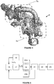
figure 2 est une représentation schématique d'un système de protection d'une roue d'un compresseur d'un turbocompresseur d'un groupe motopropulseur d'un véhicule, selon le mode de réalisation de l'invention ;
- la
figure 3 est une représentation schématique du groupe motopropulseur du véhicule comprenant un ensemble de suralimention comportant un turbocompresseur haute-pression et un turbocompresseur basse-pression, selon le mode de réalisation de l'invention ; - la
figure 4 représente l'ensemble de suralimention comportant les turbocompresseurs haute-pression et basse-pression, selon le mode de réalisation de l'invention, et - la
figure 5 un logigramme d'un procédé de protection de la roue de compresseur du turbocompresseur, selon le mode de réalisation de l'invention.
- the
figure 1 represents a curve relating to the evolution of the temperature of a compressor wheel in time during a stopping of the thermal engine in the state of the art; - the
figure 2 is a schematic representation of a system for protecting a wheel of a compressor of a turbocharger a powertrain of a vehicle, according to the embodiment of the invention;
- the
figure 3 is a schematic representation of the powertrain of the vehicle comprising a supercharger assembly comprising a high-pressure turbocharger and a low-pressure turbocharger, according to the embodiment of the invention; - the
figure 4 represents the supercharger assembly comprising the high-pressure and low-pressure turbochargers, according to the embodiment of the invention, and - the
figure 5 a flow chart of a method of protecting the turbocharger compressor wheel, according to the embodiment of the invention.
Dans la description qui va suivre, des chiffres de référence identiques désignent des pièces identiques ou ayant des fonctions similaires.In the following description, like reference numerals designate like parts or having similar functions.
En référence à la
Ce véhicule est équipé d'une fonction dite « Stop & Start » encore appelée « Stop & Go », permettant de couper automatiquement le moteur 6 lors d'un arrêt prolongé et de le redémarrer instantanément et en silence. Par exemple, cette prestation peut être obtenue par le moyen d'un alterno-démarreur, qui remplace le démarreur classique sans qu'il soit nécessaire de modifier l'architecture classique du moteur 6. S'agissant du moteur hybride, le moteur thermique est susceptible d'être arrêté pendant certaines phases de roulage, et l'alterno-démarreur redémarre alors le moteur thermique après une phase de propulsion électrique. On notera que de manière alternative une telle fonction « Stop & Start » peut également être réalisée par un démarreur renforcé.This vehicle is equipped with a function called "Stop &Start" called "Stop &Go", to automatically turn off the engine 6 during a prolonged stop and restart it instantly and silently. For example, this benefit can be obtained by the means an alternator-starter, which replaces the conventional starter without the need to modify the conventional architecture of the engine 6. With regard to the hybrid engine, the heat engine may be stopped during certain driving phases, and the alternator-starter then restarts the engine after an electric propulsion phase. It will be noted that alternatively such a "Stop &Start" function can also be performed by a reinforced starter.
Sur les
Dans cette configuration, chaque turbocompresseur 7a, 7b est un dispositif de suralimentation formé d'une turbine 9a, 9b et d'un compresseur 10a, 10b entraîné en rotation par la turbine 9a, 9b, à travers un arbre 13a, 13b reliant une roue 11 a, 11 b de turbine 9a, 9b et la roue 12a, 12b de compresseur 10a, 10b. La roue 11 a, 11 b de turbine 9a, 9b est disposée sur le trajet des gaz d'échappement du moteur thermique 6 dans la ligne d'échappement 14b et est entraînée en rotation par les gaz s'échappant de ce moteur 6. La roue 12a, 12b de compresseur 10a, 10b est disposée sur le trajet d'admission d'air dans la ligne d'admission d'air 14a du moteur 6. Il compresse l'air injecté dans le moteur 6, permettant une suralimentation du moteur 6 par rapport à un régime d'admission à la pression atmosphérique. On notera qu'une telle roue 12a, 12b de compresseur 10a, 10b peut être fabriquée selon un procédé d'usinage ou de moulage.
Le système de protection 1 comprend une unité de traitement 2, un dispositif de contrôle 3 du fonctionnement du moteur 6 et des capteurs de température 4a, 4b ainsi qu'un réseau de liaison 15 notamment un réseau filaire ou sans fil.In this configuration, each
The protection system 1 comprises a
Dans ce système 1, le réseau de liaison 15 relie l'unité de traitement 2, les capteurs de température 4a, 4b et le dispositif de contrôle 3 du fonctionnement du moteur 6 entre eux.In this system 1, the
L'unité de traitement 2 comprend des ressources matérielles et logicielles et plus précisément au moins un processeur coopérant avec des éléments de mémoire. Ces ressources matérielles et logicielles sont aptes à exécuter des instructions pour la mise en oeuvre d'un programme d'ordinateur.The
Le dispositif de contrôle 3 du fonctionnement du moteur 6 comprend un calculateur 5 qui est apte à piloter différentes composantes du moteur 6 telles que les injecteurs de carburant, des vannes de régulation de l'arrivée de gaz frais dans le moteur 6, des vannes de décharge associées aux turbocompresseurs 7a, 7b, des vannes de recyclage des gaz d'échappement , etc...Ce calculateur 5 est également relié à différents capteurs de contrôle du fonctionnement des composantes du moteur 6.The control device 3 of the operation of the engine 6 comprises a
Un tel dispositif de contrôle 3 est prévu pour piloter le fonctionnement du moteur 6 selon des configurations correspondant à différents modes de fonctionnement de ce moteur 6 dont notamment des modes de fonctionnement du moteur 6 dommageable et non-dommageable pour une roue 12a, 12b de compresseur 10a, 10b décrits par la suite. Ce dispositif 3 est également apte à réaliser l'arrêt du moteur 6 ou le démarrage de ce dernier.
Dans ce mode de réalisation, les capteurs de température 4a, 4b sont de préférence au nombre de deux. Ces capteurs 4a, 4b sont agencés en amont et en aval de la roue 12a de compresseur 10a du turbocompresseur haute-pression 7a. Les termes amont et aval sont définis selon le sens de circulation de l'air dans la ligne d'admission d'air 14a du moteur 6. Ces capteurs 4a, 4b sont de préférence disposés à l'entrée et à la sortie du compresseur du turbocompresseur haute-pression 7a.Such a control device 3 is provided to control the operation of the engine 6 in configurations corresponding to different modes of operation of this engine 6, including operating modes of the engine 6 damaging and non-damaging for a
In this embodiment, the
En référence à la
Ce procédé comprend une étape de réception 16 d'une requête relative à une demande d'arrêt du moteur 6. Lors de cette étape 16, l'unité de traitement 2 peut donc recevoir une telle requête dans le cadre de la réalisation de la fonction « Stop & Start » ou de l'arrêt du moteur 6 thermique dans le cas d'une phase de propulsion électrique lorsque le véhicule est équipé du moteur hybride.This method comprises a
Le procédé comprend également une étape d'évaluation 17 en continue d'une température Tr de la roue 12a de compresseur 10a. Cette étape 17 comprend une sous-étape de détermination 18 par l'unité de traitement 2 de températures en amont et en aval Tam, Tav de la roue 12a de compresseur 10a du gaz circulant dans la ligne d'admission d'air 14a du moteur 6.The method also comprises a
Plus précisément, ces températures en amont et en aval Tam, Tav sont déterminées à partir de mesures de ces températures Tam, Tav réalisées par les capteurs de température 4a, 4b au niveau respectivement de l'entrée et de la sortie du compresseur 10a et qui sont transmises à l'unité de traitement 2. Dans ce contexte, en première approche, la température Tr de la roue 12a correspond à la moyenne des températures en amont et en aval Tam, Tav de cette roue 12a. On notera que la température Tr de la roue 12a peut être déterminée par des calculs plus élaborés à partir des températures Tam et Tav.More specifically, these upstream and downstream temperatures Tam, Tav are determined from measurements of these temperatures Tam, Tav carried out by the
De manière alternative, ces températures Tam, Tav peuvent être estimées à partir de données relatives à un modèle de suralimentation archivées dans les éléments de mémoire de l'unité de traitement 2.Alternatively, these temperatures Tam, Tav can be estimated from data relating to a supercharging model stored in the memory elements of the
Ce données sont préalablement obtenues par un outil de calcul qui reproduit le fonctionnement de la suralimentation à partir d'éléments comme la températures air et gaz, le débit d'air et de gaz, la pression de l'air et de gaz, et/ou du régime moteur. A partir de ces éléments pouvant être mesurés sur plusieurs moteurs, cet outil de calcul détermine des paramètres plus élaborés dans notre cas, les températures Tam et Tav sans qu'il soit nécessaire de les mesurer au moyen de capteurs.This data is previously obtained by a calculation tool that reproduces the operation of the supercharging from elements such as air and gas temperatures, the flow of air and gas, air and gas pressure, and / or or engine speed. From these elements which can be measured on several engines, this calculation tool determines more elaborate parameters in our case, the temperatures Tam and Tav without it being necessary to measure them by means of sensors.
Le procédé comprend ensuite une étape d'arrêt 18 du moteur si la température Tr de la roue 12a de compresseur 10a est inférieure ou égale à une température de consigne Tc. Dans ces conditions, l'unité de traitement 2 transmet une requête au dispositif de contrôle 3 du fonctionnement du moteur 6 visant à arrêter le moteur 6. Ce moteur 6 peut par la suite être redémarré par le dispositif de contrôle 3 du fonctionnement du moteur 6 dès lors que l'unité de traitement 2 reçoit une requête de mise en marche de ce moteur 6. À la suite de cette étape 18, l'unité de traitement reste en attente d'une nouvelle requête de demande d'arrêt du moteur 6 mise en oeuvre lors de l'étape de réception 16.The method then comprises a stopping
Le procédé comprend aussi une étape d'inhibition 19 d'un arrêt du moteur 6 du véhicule lorsque la température Tr de la roue 12a de compresseur 10a est supérieure à la température de consigne Tc si le moteur 6 est dans un mode de fonctionnement dommageable pour ladite roue 12a de compresseur 10a.The method also comprises a
Le moteur 6 est dans un mode de fonctionnement dommageable pour la roue 12a de compresseur 10a dès lors que celui-ci met en oeuvre un fonctionnement qui maintien le turbocompresseur 7a, 7b et en particulier la roue 12a de compresseur 10a sous l'effet d'une forte sollicitation thermique lors de l'arrêt du moteur 6. Ce mode de fonctionnement peut alors entraîner des modifications structurelles des éléments composant le turbocompresseur 7a, 7b dont en particulier de la roue 12a de compresseur 10a et ce, lorsqu'un arrêt du moteur 6 est réalisé. Ces modifications structurelles de la roue 12a de compresseur 10a résultent dès lors de dépassements de la limite thermique de cette roue. A titre d'exemple non limitatif et non exhaustif, ce mode de fonctionnement dommageable comprend :
- un processus de régénération d'un filtre à particules, ou
- un processus de maintien de la température Tr de la roue 12a de compresseur 10a à une valeur supérieure à celle d'une température seuil Ts pendant une durée di qui est supérieure à une durée seuil ds, ou
- un processus de maintien de la température Tav en aval de la roue 12a de compresseur 10a à une valeur supérieure à celle d'une température seuil Ts pendant une durée di qui est supérieure à une durée seuil ds.
- a regeneration process of a particulate filter, or
- a process for maintaining the temperature Tr of the
compressor wheel 12a at a value greater than that of a threshold temperature Ts for a duration di which is greater than a threshold duration ds, or - a process for maintaining the temperature Tav downstream of the
compressor wheel 12a 10a to a value greater than that of a threshold temperature Ts for a duration di which is greater than a threshold duration ds.
Dans ce contexte, lors de la réalisation de cette étape 19, l'unité de traitement 2 interdit alors l'arrêt du moteur 6 lorsque la température Tr de la roue 12a de compresseur 10a est supérieure à la température de consigne Tc et ce, si le moteur 6 est dans un mode de fonctionnement où :
- la régénération du filtre à particules est en cours, ou
- la température Tr de la roue est maintenue à une valeur supérieure à celle d'une température seuil Ts pendant la durée di supérieure à la durée seuil ds ou
- la température Tav aval de la roue 12a de compresseur 10a est maintenue à une valeur supérieure à celle d'une température seuil Ts pendant la durée di supérieure à la durée seuil ds
- regeneration of the particulate filter is in progress, or
- the temperature Tr of the wheel is maintained at a value greater than that of a threshold temperature Ts during the duration di greater than the threshold duration ds or
- the temperature Tav downstream of the
compressor wheel 12a 10a is maintained at a value greater than that of a threshold temperature Ts during the duration di greater than the threshold duration ds
L'étape d'inhibition 19 comprend une sous-étape de déclenchement 20a de l'inhibition de l'arrêt du moteur 6 dès que la température Tr de la roue 12a de compresseur 10a est supérieure à la température de consigne Tc. Autrement dit, dès lors que l'unité de traitement 2 détermine la température Tr et que cette température Tr est supérieure à la température de consigne Tc lors d'un processus de comparaison, elle interdit alors l'arrêt du moteur 6 en n'envoyant pas d'instruction au dispositif de contrôle 3 du moteur 6. Dans ce contexte, l'unité de traitement 2 inhibe l'arrêt du moteur 6 immédiatement après l'établissement de la relation entre les températures Tr de la roue 12a et de consigne Tc c'est-à-dire la température Tr de la roue qui est supérieure à la température de consigne Tc.The
De manière alternative, l'étape d'inhibition 19 peut comprendre une sous-étape de déclenchement 20b de l'inhibition de l'arrêt du moteur 6 qui est réalisée après une durée dr pendant laquelle la température Tr de la roue 12a de compresseur 10a est supérieure à la température de consigne Tc si cette durée dr est supérieure à une durée de consigne dc. Autrement dit, l'unité de traitement 2 n'inhibe pas l'arrêt du moteur 6 immédiatement après l'établissement que la température Tr de la roue est supérieure à la température de consigne Tc. En effet, cette inhibition de l'arrêt du moteur 6 est réalisée seulement si un tel rapport entre ces températures Tr et Tc est maintenu pendant une durée dr qui est supérieure à la durée de consigne dc.Alternatively, the
Par la suite, l'étape d'inhibition 19 comprend une sous-étape d'interruption de l'inhibition 21 de l'arrêt du moteur 6 si une durée di pendant laquelle la température Tr de la roue 12a de compresseur 10a est inférieure ou égale à la température de consigne Tc, est supérieure à une durée seuil ds. Plus précisément, lors de cette sous-étape 21, l'unité de traitement 2 compare la température Tr à la température de consigne Tc. Dès lors que cette unité de traitement 2 détermine que la température Tr de la roue 12a de compresseur 10a est inférieure ou égale à la température de consigne Tc, elle compare la durée di pendant laquelle cette relation entre ces deux températures Tr, Tc ne varie pas, avec cette durée seuil ds. A compter du moment où l'unité de traitement 2 détermine que la durée di est supérieure à la durée seuil ds, elle déclenche alors l'interruption de l'inhibition de l'arrêt du moteur 6.Subsequently, the
Dans ce contexte, le moteur 6 peut être déjà en marche ou être redémarré par le dispositif de contrôle 3 du fonctionnement du moteur 6. À la suite de cette sous-étape 21, l'unité de traitement 2 reste en attente d'une nouvelle requête de demande d'arrêt du moteur 6 mise en oeuvre lors de l'étape de réception 16.In this context, the engine 6 may already be running or restarted by the control device 3 of the operation of the engine 6. Following this
Le procédé comprend aussi une étape de configuration 22 du moteur 6 selon un mode de fonctionnement non-dommageable pour ladite roue 12a de compresseur 10a si une valeur Vi incrémentée d'un compteur représentatif d'un nombre de fois où le moteur 6 est arrêté lorsque ledit moteur 6 est dans un mode de fonctionnement dommageable pour la roue 12a de compresseur 10a, est supérieure à une valeur de référence Vr.The method also comprises a
Le moteur 6 est dans un mode de fonctionnement non-dommageable pour la roue 12a de compresseur 10a dès lors que celui-ci met en oeuvre un fonctionnement qui permet de maintenir la température Tr de la roue 12a de compresseur 10a à une valeur qui est inférieure ou égale à la température de consigne Tc. Dans ces conditions, ce mode de fonctionnement vise à ne pas entraîner de modifications structurelle des éléments composant le compresseur 7a, 7b dont en particulier la roue 12a de compresseur 10a et ce, lorsqu'un arrêt du moteur 6 est réalisé. A titre d'exemple non limitatif et non exhaustif, ce mode de fonctionnement dommageable comprend un processus de fonctionnement en sous-régime du moteur 6.The engine 6 is in a non-damaging operating mode for the
Lors de la réalisation de cette étape 22, l'unité de traitement 2 incrémente la valeur Vi du compteur dès lors que le moteur 6 est arrêté alors qu'il est dans un mode de fonctionnement dommageable pour la roue 12a de compresseur 10a. A chaque incrémentation de la valeur Vi, l'unité de traitement 2 met en oeuvre une comparaison de cette valeur Vi avec la valeur de référence Vr. A compter du moment où l'unité de traitement 2 détermine que cette valeur Vi est supérieure à la valeur de référence Vr, elle transmet une requête au dispositif de contrôle 3 du fonctionnement du moteur 6 afin que ce dernier applique une configuration prédéfinie au moteur 6 visant à le faire marcher selon un mode de fonctionnement non-dommageable pour la roue 12a de compresseur 10a.When performing this
On notera qu'une telle étape 22 permet notamment d'assurer une protection optimale de la roue 12a de compresseur 10a lorsque l'arrêt du moteur 6 résulte de manière directe d'un utilisateur du véhicule par exemple à la suite d'un stationnement de ce dernier ou à la suite d'une interruption d'utilisation du véhicule.It will be noted that such a
Dans cette étape 22, lorsque la valeur Vi est inférieure ou égale à la valeur de référence Vr, l'unité de traitement 2 continue de réaliser à chaque incrémentation une comparaison de ces deux valeurs Vi, Vr entre elles.In this
Cette étape de configuration 22 comprend une sous-étape d'initialisation 23 du compteur. On notera que cette sous-étape 23 se fait au kilomètre zéro et ne cesse de s'incrémenter tout au long de la vie du moteur et/ou véhicule. Ce compteur n'est pas remis à zéro par la suite sauf lors de changement de certain type de pièce dans le véhicule comme un dispositif de suralimentation tel qu'un turbocompresseur.This
On notera que la valeur de référence Vs et les températures de seuil et de consigne Ts, Tc ainsi que les durées de seuil et de consigne ds, dc sont paramétrables et sont définies selon les caractéristiques du moteur 6 du véhicule, du turbocompresseur 7a, du matériau constituant la roue 12a de compresseur 10a et/ou des dimensions de cette roue 12a.It will be noted that the reference value Vs and the threshold and setpoint temperatures Ts, Tc as well as the threshold and setpoint durations ds, dc are parameterizable and are defined according to the characteristics of the engine 6 of the vehicle, the
L'invention porte également sur le programme d'ordinateur comprenant des instructions de code de programme pour l'exécution de telles étapes 16 à 23 du procédé lorsque ledit programme est exécuté par l'unité de traitement 2 du système 1.The invention also relates to the computer program comprising program code instructions for executing
Ainsi, l'invention permet de préserver la dureté de la roue de compresseur et d'éviter des dépassements de la limite thermique de cette roue.Thus, the invention makes it possible to preserve the hardness of the compressor wheel and to avoid exceeding the thermal limit of this wheel.
Claims (10)
Applications Claiming Priority (1)
| Application Number | Priority Date | Filing Date | Title |
|---|---|---|---|
| FR1661948A FR3059722B1 (en) | 2016-12-05 | 2016-12-05 | METHOD AND SYSTEM FOR PROTECTING A WHEEL OF A COMPRESSOR OF A TURBOCHARGER |
Publications (2)
| Publication Number | Publication Date |
|---|---|
| EP3330520A1 true EP3330520A1 (en) | 2018-06-06 |
| EP3330520B1 EP3330520B1 (en) | 2019-08-28 |
Family
ID=57909734
Family Applications (1)
| Application Number | Title | Priority Date | Filing Date |
|---|---|---|---|
| EP17191614.1A Active EP3330520B1 (en) | 2016-12-05 | 2017-09-18 | Method and system for protecting a turbocharger compressor wheel |
Country Status (2)
| Country | Link |
|---|---|
| EP (1) | EP3330520B1 (en) |
| FR (1) | FR3059722B1 (en) |
Cited By (1)
| Publication number | Priority date | Publication date | Assignee | Title |
|---|---|---|---|---|
| FR3106372A1 (en) | 2020-01-21 | 2021-07-23 | Renault S.A.S | Device and method for regulating a downstream temperature of a fluid flow passing through a compressor |
Citations (3)
| Publication number | Priority date | Publication date | Assignee | Title |
|---|---|---|---|---|
| JPH0942003A (en) * | 1995-07-26 | 1997-02-10 | Hino Motors Ltd | Automatic engine stopping device |
| FR2942505A1 (en) * | 2009-02-24 | 2010-08-27 | Renault Sas | METHOD FOR MANAGING THE AUTOMATIC STOP OF THE MOTOR OF A MOTOR VEHICLE |
| US20130074795A1 (en) * | 2011-09-21 | 2013-03-28 | GM Global Technology Operations LLC | Method for controlling an automatic start-stop mechanism |
-
2016
- 2016-12-05 FR FR1661948A patent/FR3059722B1/en not_active Expired - Fee Related
-
2017
- 2017-09-18 EP EP17191614.1A patent/EP3330520B1/en active Active
Patent Citations (3)
| Publication number | Priority date | Publication date | Assignee | Title |
|---|---|---|---|---|
| JPH0942003A (en) * | 1995-07-26 | 1997-02-10 | Hino Motors Ltd | Automatic engine stopping device |
| FR2942505A1 (en) * | 2009-02-24 | 2010-08-27 | Renault Sas | METHOD FOR MANAGING THE AUTOMATIC STOP OF THE MOTOR OF A MOTOR VEHICLE |
| US20130074795A1 (en) * | 2011-09-21 | 2013-03-28 | GM Global Technology Operations LLC | Method for controlling an automatic start-stop mechanism |
Cited By (2)
| Publication number | Priority date | Publication date | Assignee | Title |
|---|---|---|---|---|
| FR3106372A1 (en) | 2020-01-21 | 2021-07-23 | Renault S.A.S | Device and method for regulating a downstream temperature of a fluid flow passing through a compressor |
| EP3855009A1 (en) | 2020-01-21 | 2021-07-28 | RENAULT s.a.s. | Device and method for controlling a downstream temperature of a fluid stream passing through a compressor of an internal combustion engine |
Also Published As
| Publication number | Publication date |
|---|---|
| FR3059722A1 (en) | 2018-06-08 |
| EP3330520B1 (en) | 2019-08-28 |
| FR3059722B1 (en) | 2019-05-17 |
Similar Documents
| Publication | Publication Date | Title |
|---|---|---|
| EP3092382B1 (en) | Exhaust gas line of an internal combustion engine and internal combustion engine with such an exhaust gas line | |
| EP2986833B1 (en) | Method for improving the energy efficiency of a drive system | |
| EP3330520B1 (en) | Method and system for protecting a turbocharger compressor wheel | |
| EP1834074B1 (en) | Protecting an oxidation catalyst upstream of a particulate filter for a diesel engine by limitation of injected fuel | |
| EP3535483A1 (en) | System for injecting air into a gas exhaust circuit of a supercharged heat engine | |
| EP1293658B1 (en) | Method and system for controlling the air flow in an intake manifold of an internal combustion engine of a vehicle | |
| FR2860033A1 (en) | Exhaust gas purification system, for treating exhaust emitted from internal combustion engine, feeds fuel into precious metal particulate trap to raise temperature and oxidize particulates | |
| FR2951785A1 (en) | METHOD FOR CONTROLLING THE AUTOMATIC STOP OF AN INTERNAL COMBUSTION ENGINE OF A MOTOR VEHICLE | |
| EP1832728B1 (en) | Device for pollution control of the exhaust gases from an internal combustion engine | |
| EP3353404A1 (en) | Method for producing a control instruction of an electrical compressor | |
| FR3015562A1 (en) | ASSEMBLY COMPRISING A THERMAL MOTOR AND AN ELECTRICAL COMPRESSOR CONFIGURED TO SCAN RESIDUAL BURNED GASES | |
| FR2802241A1 (en) | Malfunction detector for an internal exhaust gas system compares actual setting on valve connecting exhaust system to admission system with target setting obtained with new exhaust gas system | |
| FR2882576A1 (en) | Internal combustion engine e.g. diesel engine, controlling method for motor vehicle, involves determining maximum value for pressure drop ratio set point such that during transitional stage adjusted pressure drop ratio is less than value | |
| FR3028565A1 (en) | METHOD FOR DIAGNOSING THE INHIBITION OF AN AIR FILTER EQUIPPED WITH A SUPERIOR INTERNAL COMBUSTION ENGINE | |
| FR2917785A1 (en) | Exhaust gas purification controlling unit for internal combustion engine i.e. oil engine, of vehicle, has control unit acting as device to reduce quantity based on temperature according to increase of purification capacity of catalyst | |
| FR3029571A3 (en) | METHOD FOR CONTROLLING A MOTORIZATION DEVICE AND ASSOCIATED MOTORIZATION DEVICE | |
| EP3808959A1 (en) | Method for controlling the supercharging of air in an internal combustion engine | |
| FR3045107A1 (en) | METHOD FOR MINIMIZING PUMPING LOSSES IN A THERMAL ENGINE DURING STARTING | |
| EP4276297A1 (en) | Method for adjusting the partial recirculation of exhaust gases to the intake of a diesel engine | |
| FR2997498A1 (en) | Method for diagnosing exhaust gas recirculation system in internal combustion engine of car, involves developing control of recirculation valve to reduce error, and reporting system fault if error exceeds interval of tolerance | |
| WO2019048781A1 (en) | Engine assembly comprising a turbocharger and an electrical supercharger | |
| FR2983522A1 (en) | Method for regenerating e.g. particle filter, of exhaust gases emitted by diesel engine of power train of car, involves estimating effectiveness of regeneration, and determining setpoint temperature based on estimated effectiveness | |
| EP2128414A1 (en) | Engine control method | |
| FR3104210A1 (en) | PROCESS FOR LIMITING THE QUANTITY OF POLLUTANTS RELEASED BY A HYBRID VEHICLE THERMAL ENGINE | |
| FR2942501A1 (en) | Fuel i.e. diesel, quantity regulating device for motor vehicle, has control unit increasing setpoint temperature at inlet of filter only after verifying that difference between input and output temperatures is lower than threshold gradient |
Legal Events
| Date | Code | Title | Description |
|---|---|---|---|
| PUAI | Public reference made under article 153(3) epc to a published international application that has entered the european phase |
Free format text: ORIGINAL CODE: 0009012 |
|
| STAA | Information on the status of an ep patent application or granted ep patent |
Free format text: STATUS: THE APPLICATION HAS BEEN PUBLISHED |
|
| AK | Designated contracting states |
Kind code of ref document: A1 Designated state(s): AL AT BE BG CH CY CZ DE DK EE ES FI FR GB GR HR HU IE IS IT LI LT LU LV MC MK MT NL NO PL PT RO RS SE SI SK SM TR |
|
| AX | Request for extension of the european patent |
Extension state: BA ME |
|
| STAA | Information on the status of an ep patent application or granted ep patent |
Free format text: STATUS: REQUEST FOR EXAMINATION WAS MADE |
|
| 17P | Request for examination filed |
Effective date: 20181206 |
|
| RBV | Designated contracting states (corrected) |
Designated state(s): AL AT BE BG CH CY CZ DE DK EE ES FI FR GB GR HR HU IE IS IT LI LT LU LV MC MK MT NL NO PL PT RO RS SE SI SK SM TR |
|
| RIC1 | Information provided on ipc code assigned before grant |
Ipc: F02N 11/08 20060101ALI20190305BHEP Ipc: F02B 37/00 20060101ALI20190305BHEP Ipc: F02B 37/10 20060101ALI20190305BHEP Ipc: F01N 9/00 20060101ALI20190305BHEP Ipc: F02B 39/16 20060101ALI20190305BHEP Ipc: F02D 41/00 20060101AFI20190305BHEP |
|
| GRAP | Despatch of communication of intention to grant a patent |
Free format text: ORIGINAL CODE: EPIDOSNIGR1 |
|
| STAA | Information on the status of an ep patent application or granted ep patent |
Free format text: STATUS: GRANT OF PATENT IS INTENDED |
|
| INTG | Intention to grant announced |
Effective date: 20190417 |
|
| RIN1 | Information on inventor provided before grant (corrected) |
Inventor name: DIDIOT, BENJAMIN |
|
| GRAS | Grant fee paid |
Free format text: ORIGINAL CODE: EPIDOSNIGR3 |
|
| GRAA | (expected) grant |
Free format text: ORIGINAL CODE: 0009210 |
|
| STAA | Information on the status of an ep patent application or granted ep patent |
Free format text: STATUS: THE PATENT HAS BEEN GRANTED |
|
| AK | Designated contracting states |
Kind code of ref document: B1 Designated state(s): AL AT BE BG CH CY CZ DE DK EE ES FI FR GB GR HR HU IE IS IT LI LT LU LV MC MK MT NL NO PL PT RO RS SE SI SK SM TR |
|
| REG | Reference to a national code |
Ref country code: GB Ref legal event code: FG4D Free format text: NOT ENGLISH |
|
| REG | Reference to a national code |
Ref country code: CH Ref legal event code: EP |
|
| REG | Reference to a national code |
Ref country code: AT Ref legal event code: REF Ref document number: 1172705 Country of ref document: AT Kind code of ref document: T Effective date: 20190915 |
|
| REG | Reference to a national code |
Ref country code: IE Ref legal event code: FG4D Free format text: LANGUAGE OF EP DOCUMENT: FRENCH |
|
| REG | Reference to a national code |
Ref country code: DE Ref legal event code: R096 Ref document number: 602017006496 Country of ref document: DE |
|
| REG | Reference to a national code |
Ref country code: NL Ref legal event code: MP Effective date: 20190828 |
|
| REG | Reference to a national code |
Ref country code: LT Ref legal event code: MG4D |
|
| PG25 | Lapsed in a contracting state [announced via postgrant information from national office to epo] |
Ref country code: NL Free format text: LAPSE BECAUSE OF FAILURE TO SUBMIT A TRANSLATION OF THE DESCRIPTION OR TO PAY THE FEE WITHIN THE PRESCRIBED TIME-LIMIT Effective date: 20190828 Ref country code: BG Free format text: LAPSE BECAUSE OF FAILURE TO SUBMIT A TRANSLATION OF THE DESCRIPTION OR TO PAY THE FEE WITHIN THE PRESCRIBED TIME-LIMIT Effective date: 20191128 Ref country code: LT Free format text: LAPSE BECAUSE OF FAILURE TO SUBMIT A TRANSLATION OF THE DESCRIPTION OR TO PAY THE FEE WITHIN THE PRESCRIBED TIME-LIMIT Effective date: 20190828 Ref country code: PT Free format text: LAPSE BECAUSE OF FAILURE TO SUBMIT A TRANSLATION OF THE DESCRIPTION OR TO PAY THE FEE WITHIN THE PRESCRIBED TIME-LIMIT Effective date: 20191230 Ref country code: HR Free format text: LAPSE BECAUSE OF FAILURE TO SUBMIT A TRANSLATION OF THE DESCRIPTION OR TO PAY THE FEE WITHIN THE PRESCRIBED TIME-LIMIT Effective date: 20190828 Ref country code: SE Free format text: LAPSE BECAUSE OF FAILURE TO SUBMIT A TRANSLATION OF THE DESCRIPTION OR TO PAY THE FEE WITHIN THE PRESCRIBED TIME-LIMIT Effective date: 20190828 Ref country code: NO Free format text: LAPSE BECAUSE OF FAILURE TO SUBMIT A TRANSLATION OF THE DESCRIPTION OR TO PAY THE FEE WITHIN THE PRESCRIBED TIME-LIMIT Effective date: 20191128 Ref country code: FI Free format text: LAPSE BECAUSE OF FAILURE TO SUBMIT A TRANSLATION OF THE DESCRIPTION OR TO PAY THE FEE WITHIN THE PRESCRIBED TIME-LIMIT Effective date: 20190828 |
|
| PG25 | Lapsed in a contracting state [announced via postgrant information from national office to epo] |
Ref country code: ES Free format text: LAPSE BECAUSE OF FAILURE TO SUBMIT A TRANSLATION OF THE DESCRIPTION OR TO PAY THE FEE WITHIN THE PRESCRIBED TIME-LIMIT Effective date: 20190828 Ref country code: IS Free format text: LAPSE BECAUSE OF FAILURE TO SUBMIT A TRANSLATION OF THE DESCRIPTION OR TO PAY THE FEE WITHIN THE PRESCRIBED TIME-LIMIT Effective date: 20191228 Ref country code: RS Free format text: LAPSE BECAUSE OF FAILURE TO SUBMIT A TRANSLATION OF THE DESCRIPTION OR TO PAY THE FEE WITHIN THE PRESCRIBED TIME-LIMIT Effective date: 20190828 Ref country code: GR Free format text: LAPSE BECAUSE OF FAILURE TO SUBMIT A TRANSLATION OF THE DESCRIPTION OR TO PAY THE FEE WITHIN THE PRESCRIBED TIME-LIMIT Effective date: 20191129 Ref country code: AL Free format text: LAPSE BECAUSE OF FAILURE TO SUBMIT A TRANSLATION OF THE DESCRIPTION OR TO PAY THE FEE WITHIN THE PRESCRIBED TIME-LIMIT Effective date: 20190828 Ref country code: LV Free format text: LAPSE BECAUSE OF FAILURE TO SUBMIT A TRANSLATION OF THE DESCRIPTION OR TO PAY THE FEE WITHIN THE PRESCRIBED TIME-LIMIT Effective date: 20190828 |
|
| REG | Reference to a national code |
Ref country code: AT Ref legal event code: MK05 Ref document number: 1172705 Country of ref document: AT Kind code of ref document: T Effective date: 20190828 |
|
| PG25 | Lapsed in a contracting state [announced via postgrant information from national office to epo] |
Ref country code: TR Free format text: LAPSE BECAUSE OF FAILURE TO SUBMIT A TRANSLATION OF THE DESCRIPTION OR TO PAY THE FEE WITHIN THE PRESCRIBED TIME-LIMIT Effective date: 20190828 |
|
| PG25 | Lapsed in a contracting state [announced via postgrant information from national office to epo] |
Ref country code: RO Free format text: LAPSE BECAUSE OF FAILURE TO SUBMIT A TRANSLATION OF THE DESCRIPTION OR TO PAY THE FEE WITHIN THE PRESCRIBED TIME-LIMIT Effective date: 20190828 Ref country code: EE Free format text: LAPSE BECAUSE OF FAILURE TO SUBMIT A TRANSLATION OF THE DESCRIPTION OR TO PAY THE FEE WITHIN THE PRESCRIBED TIME-LIMIT Effective date: 20190828 Ref country code: IT Free format text: LAPSE BECAUSE OF FAILURE TO SUBMIT A TRANSLATION OF THE DESCRIPTION OR TO PAY THE FEE WITHIN THE PRESCRIBED TIME-LIMIT Effective date: 20190828 Ref country code: AT Free format text: LAPSE BECAUSE OF FAILURE TO SUBMIT A TRANSLATION OF THE DESCRIPTION OR TO PAY THE FEE WITHIN THE PRESCRIBED TIME-LIMIT Effective date: 20190828 Ref country code: DK Free format text: LAPSE BECAUSE OF FAILURE TO SUBMIT A TRANSLATION OF THE DESCRIPTION OR TO PAY THE FEE WITHIN THE PRESCRIBED TIME-LIMIT Effective date: 20190828 Ref country code: PL Free format text: LAPSE BECAUSE OF FAILURE TO SUBMIT A TRANSLATION OF THE DESCRIPTION OR TO PAY THE FEE WITHIN THE PRESCRIBED TIME-LIMIT Effective date: 20190828 |
|
| PG25 | Lapsed in a contracting state [announced via postgrant information from national office to epo] |
Ref country code: IS Free format text: LAPSE BECAUSE OF FAILURE TO SUBMIT A TRANSLATION OF THE DESCRIPTION OR TO PAY THE FEE WITHIN THE PRESCRIBED TIME-LIMIT Effective date: 20200224 Ref country code: MC Free format text: LAPSE BECAUSE OF FAILURE TO SUBMIT A TRANSLATION OF THE DESCRIPTION OR TO PAY THE FEE WITHIN THE PRESCRIBED TIME-LIMIT Effective date: 20190828 Ref country code: SK Free format text: LAPSE BECAUSE OF FAILURE TO SUBMIT A TRANSLATION OF THE DESCRIPTION OR TO PAY THE FEE WITHIN THE PRESCRIBED TIME-LIMIT Effective date: 20190828 Ref country code: SM Free format text: LAPSE BECAUSE OF FAILURE TO SUBMIT A TRANSLATION OF THE DESCRIPTION OR TO PAY THE FEE WITHIN THE PRESCRIBED TIME-LIMIT Effective date: 20190828 Ref country code: CZ Free format text: LAPSE BECAUSE OF FAILURE TO SUBMIT A TRANSLATION OF THE DESCRIPTION OR TO PAY THE FEE WITHIN THE PRESCRIBED TIME-LIMIT Effective date: 20190828 |
|
| REG | Reference to a national code |
Ref country code: DE Ref legal event code: R097 Ref document number: 602017006496 Country of ref document: DE |
|
| PLBE | No opposition filed within time limit |
Free format text: ORIGINAL CODE: 0009261 |
|
| STAA | Information on the status of an ep patent application or granted ep patent |
Free format text: STATUS: NO OPPOSITION FILED WITHIN TIME LIMIT |
|
| PG2D | Information on lapse in contracting state deleted |
Ref country code: IS |
|
| PG25 | Lapsed in a contracting state [announced via postgrant information from national office to epo] |
Ref country code: LU Free format text: LAPSE BECAUSE OF NON-PAYMENT OF DUE FEES Effective date: 20190918 Ref country code: IE Free format text: LAPSE BECAUSE OF NON-PAYMENT OF DUE FEES Effective date: 20190918 |
|
| 26N | No opposition filed |
Effective date: 20200603 |
|
| REG | Reference to a national code |
Ref country code: BE Ref legal event code: MM Effective date: 20190930 |
|
| PG25 | Lapsed in a contracting state [announced via postgrant information from national office to epo] |
Ref country code: BE Free format text: LAPSE BECAUSE OF NON-PAYMENT OF DUE FEES Effective date: 20190930 Ref country code: SI Free format text: LAPSE BECAUSE OF FAILURE TO SUBMIT A TRANSLATION OF THE DESCRIPTION OR TO PAY THE FEE WITHIN THE PRESCRIBED TIME-LIMIT Effective date: 20190828 |
|
| REG | Reference to a national code |
Ref country code: CH Ref legal event code: PL |
|
| PG25 | Lapsed in a contracting state [announced via postgrant information from national office to epo] |
Ref country code: CY Free format text: LAPSE BECAUSE OF FAILURE TO SUBMIT A TRANSLATION OF THE DESCRIPTION OR TO PAY THE FEE WITHIN THE PRESCRIBED TIME-LIMIT Effective date: 20190828 |
|
| PG25 | Lapsed in a contracting state [announced via postgrant information from national office to epo] |
Ref country code: MT Free format text: LAPSE BECAUSE OF FAILURE TO SUBMIT A TRANSLATION OF THE DESCRIPTION OR TO PAY THE FEE WITHIN THE PRESCRIBED TIME-LIMIT Effective date: 20190828 Ref country code: HU Free format text: LAPSE BECAUSE OF FAILURE TO SUBMIT A TRANSLATION OF THE DESCRIPTION OR TO PAY THE FEE WITHIN THE PRESCRIBED TIME-LIMIT; INVALID AB INITIO Effective date: 20170918 |
|
| PG25 | Lapsed in a contracting state [announced via postgrant information from national office to epo] |
Ref country code: LI Free format text: LAPSE BECAUSE OF NON-PAYMENT OF DUE FEES Effective date: 20200930 Ref country code: CH Free format text: LAPSE BECAUSE OF NON-PAYMENT OF DUE FEES Effective date: 20200930 |
|
| PG25 | Lapsed in a contracting state [announced via postgrant information from national office to epo] |
Ref country code: MK Free format text: LAPSE BECAUSE OF FAILURE TO SUBMIT A TRANSLATION OF THE DESCRIPTION OR TO PAY THE FEE WITHIN THE PRESCRIBED TIME-LIMIT Effective date: 20190828 |
|
| P01 | Opt-out of the competence of the unified patent court (upc) registered |
Effective date: 20230608 |
|
| PGFP | Annual fee paid to national office [announced via postgrant information from national office to epo] |
Ref country code: GB Payment date: 20230920 Year of fee payment: 7 |
|
| PGFP | Annual fee paid to national office [announced via postgrant information from national office to epo] |
Ref country code: FR Payment date: 20230928 Year of fee payment: 7 Ref country code: DE Payment date: 20230920 Year of fee payment: 7 |
|
| REG | Reference to a national code |
Ref country code: GB Ref legal event code: 732E Free format text: REGISTERED BETWEEN 20231228 AND 20240103 |