EP3330164A1 - Banking angle detection device and banking angle detection method - Google Patents
Banking angle detection device and banking angle detection method Download PDFInfo
- Publication number
- EP3330164A1 EP3330164A1 EP16832596.7A EP16832596A EP3330164A1 EP 3330164 A1 EP3330164 A1 EP 3330164A1 EP 16832596 A EP16832596 A EP 16832596A EP 3330164 A1 EP3330164 A1 EP 3330164A1
- Authority
- EP
- European Patent Office
- Prior art keywords
- bank angle
- bank
- vehicle
- calculating section
- determining
- Prior art date
- Legal status (The legal status is an assumption and is not a legal conclusion. Google has not performed a legal analysis and makes no representation as to the accuracy of the status listed.)
- Withdrawn
Links
Images

Classifications
-
- B—PERFORMING OPERATIONS; TRANSPORTING
- B62—LAND VEHICLES FOR TRAVELLING OTHERWISE THAN ON RAILS
- B62J—CYCLE SADDLES OR SEATS; AUXILIARY DEVICES OR ACCESSORIES SPECIALLY ADAPTED TO CYCLES AND NOT OTHERWISE PROVIDED FOR, e.g. ARTICLE CARRIERS OR CYCLE PROTECTORS
- B62J50/00—Arrangements specially adapted for use on cycles not provided for in main groups B62J1/00 - B62J45/00
- B62J50/20—Information-providing devices
- B62J50/21—Information-providing devices intended to provide information to rider or passenger
- B62J50/22—Information-providing devices intended to provide information to rider or passenger electronic, e.g. displays
-
- B—PERFORMING OPERATIONS; TRANSPORTING
- B60—VEHICLES IN GENERAL
- B60W—CONJOINT CONTROL OF VEHICLE SUB-UNITS OF DIFFERENT TYPE OR DIFFERENT FUNCTION; CONTROL SYSTEMS SPECIALLY ADAPTED FOR HYBRID VEHICLES; ROAD VEHICLE DRIVE CONTROL SYSTEMS FOR PURPOSES NOT RELATED TO THE CONTROL OF A PARTICULAR SUB-UNIT
- B60W40/00—Estimation or calculation of non-directly measurable driving parameters for road vehicle drive control systems not related to the control of a particular sub unit, e.g. by using mathematical models
- B60W40/10—Estimation or calculation of non-directly measurable driving parameters for road vehicle drive control systems not related to the control of a particular sub unit, e.g. by using mathematical models related to vehicle motion
- B60W40/112—Roll movement
-
- B—PERFORMING OPERATIONS; TRANSPORTING
- B62—LAND VEHICLES FOR TRAVELLING OTHERWISE THAN ON RAILS
- B62J—CYCLE SADDLES OR SEATS; AUXILIARY DEVICES OR ACCESSORIES SPECIALLY ADAPTED TO CYCLES AND NOT OTHERWISE PROVIDED FOR, e.g. ARTICLE CARRIERS OR CYCLE PROTECTORS
- B62J45/00—Electrical equipment arrangements specially adapted for use as accessories on cycles, not otherwise provided for
- B62J45/40—Sensor arrangements; Mounting thereof
- B62J45/41—Sensor arrangements; Mounting thereof characterised by the type of sensor
- B62J45/412—Speed sensors
-
- B—PERFORMING OPERATIONS; TRANSPORTING
- B62—LAND VEHICLES FOR TRAVELLING OTHERWISE THAN ON RAILS
- B62J—CYCLE SADDLES OR SEATS; AUXILIARY DEVICES OR ACCESSORIES SPECIALLY ADAPTED TO CYCLES AND NOT OTHERWISE PROVIDED FOR, e.g. ARTICLE CARRIERS OR CYCLE PROTECTORS
- B62J45/00—Electrical equipment arrangements specially adapted for use as accessories on cycles, not otherwise provided for
- B62J45/40—Sensor arrangements; Mounting thereof
- B62J45/41—Sensor arrangements; Mounting thereof characterised by the type of sensor
- B62J45/414—Acceleration sensors
-
- B—PERFORMING OPERATIONS; TRANSPORTING
- B62—LAND VEHICLES FOR TRAVELLING OTHERWISE THAN ON RAILS
- B62J—CYCLE SADDLES OR SEATS; AUXILIARY DEVICES OR ACCESSORIES SPECIALLY ADAPTED TO CYCLES AND NOT OTHERWISE PROVIDED FOR, e.g. ARTICLE CARRIERS OR CYCLE PROTECTORS
- B62J45/00—Electrical equipment arrangements specially adapted for use as accessories on cycles, not otherwise provided for
- B62J45/40—Sensor arrangements; Mounting thereof
- B62J45/41—Sensor arrangements; Mounting thereof characterised by the type of sensor
- B62J45/415—Inclination sensors
- B62J45/4151—Inclination sensors for sensing lateral inclination of the cycle
-
- B—PERFORMING OPERATIONS; TRANSPORTING
- B60—VEHICLES IN GENERAL
- B60W—CONJOINT CONTROL OF VEHICLE SUB-UNITS OF DIFFERENT TYPE OR DIFFERENT FUNCTION; CONTROL SYSTEMS SPECIALLY ADAPTED FOR HYBRID VEHICLES; ROAD VEHICLE DRIVE CONTROL SYSTEMS FOR PURPOSES NOT RELATED TO THE CONTROL OF A PARTICULAR SUB-UNIT
- B60W50/00—Details of control systems for road vehicle drive control not related to the control of a particular sub-unit, e.g. process diagnostic or vehicle driver interfaces
- B60W2050/0001—Details of the control system
- B60W2050/0019—Control system elements or transfer functions
- B60W2050/0027—Minimum/maximum value selectors
-
- B—PERFORMING OPERATIONS; TRANSPORTING
- B60—VEHICLES IN GENERAL
- B60W—CONJOINT CONTROL OF VEHICLE SUB-UNITS OF DIFFERENT TYPE OR DIFFERENT FUNCTION; CONTROL SYSTEMS SPECIALLY ADAPTED FOR HYBRID VEHICLES; ROAD VEHICLE DRIVE CONTROL SYSTEMS FOR PURPOSES NOT RELATED TO THE CONTROL OF A PARTICULAR SUB-UNIT
- B60W50/00—Details of control systems for road vehicle drive control not related to the control of a particular sub-unit, e.g. process diagnostic or vehicle driver interfaces
- B60W2050/0001—Details of the control system
- B60W2050/0043—Signal treatments, identification of variables or parameters, parameter estimation or state estimation
- B60W2050/0052—Filtering, filters
- B60W2050/0054—Cut-off filters, retarders, delaying means, dead zones, threshold values or cut-off frequency
-
- B—PERFORMING OPERATIONS; TRANSPORTING
- B60—VEHICLES IN GENERAL
- B60W—CONJOINT CONTROL OF VEHICLE SUB-UNITS OF DIFFERENT TYPE OR DIFFERENT FUNCTION; CONTROL SYSTEMS SPECIALLY ADAPTED FOR HYBRID VEHICLES; ROAD VEHICLE DRIVE CONTROL SYSTEMS FOR PURPOSES NOT RELATED TO THE CONTROL OF A PARTICULAR SUB-UNIT
- B60W2300/00—Indexing codes relating to the type of vehicle
- B60W2300/36—Cycles; Motorcycles; Scooters
-
- B—PERFORMING OPERATIONS; TRANSPORTING
- B60—VEHICLES IN GENERAL
- B60W—CONJOINT CONTROL OF VEHICLE SUB-UNITS OF DIFFERENT TYPE OR DIFFERENT FUNCTION; CONTROL SYSTEMS SPECIALLY ADAPTED FOR HYBRID VEHICLES; ROAD VEHICLE DRIVE CONTROL SYSTEMS FOR PURPOSES NOT RELATED TO THE CONTROL OF A PARTICULAR SUB-UNIT
- B60W2422/00—Indexing codes relating to the special location or mounting of sensors
-
- B—PERFORMING OPERATIONS; TRANSPORTING
- B60—VEHICLES IN GENERAL
- B60W—CONJOINT CONTROL OF VEHICLE SUB-UNITS OF DIFFERENT TYPE OR DIFFERENT FUNCTION; CONTROL SYSTEMS SPECIALLY ADAPTED FOR HYBRID VEHICLES; ROAD VEHICLE DRIVE CONTROL SYSTEMS FOR PURPOSES NOT RELATED TO THE CONTROL OF A PARTICULAR SUB-UNIT
- B60W2520/00—Input parameters relating to overall vehicle dynamics
-
- B—PERFORMING OPERATIONS; TRANSPORTING
- B60—VEHICLES IN GENERAL
- B60W—CONJOINT CONTROL OF VEHICLE SUB-UNITS OF DIFFERENT TYPE OR DIFFERENT FUNCTION; CONTROL SYSTEMS SPECIALLY ADAPTED FOR HYBRID VEHICLES; ROAD VEHICLE DRIVE CONTROL SYSTEMS FOR PURPOSES NOT RELATED TO THE CONTROL OF A PARTICULAR SUB-UNIT
- B60W2520/00—Input parameters relating to overall vehicle dynamics
- B60W2520/10—Longitudinal speed
-
- B—PERFORMING OPERATIONS; TRANSPORTING
- B60—VEHICLES IN GENERAL
- B60W—CONJOINT CONTROL OF VEHICLE SUB-UNITS OF DIFFERENT TYPE OR DIFFERENT FUNCTION; CONTROL SYSTEMS SPECIALLY ADAPTED FOR HYBRID VEHICLES; ROAD VEHICLE DRIVE CONTROL SYSTEMS FOR PURPOSES NOT RELATED TO THE CONTROL OF A PARTICULAR SUB-UNIT
- B60W2520/00—Input parameters relating to overall vehicle dynamics
- B60W2520/12—Lateral speed
- B60W2520/125—Lateral acceleration
-
- B—PERFORMING OPERATIONS; TRANSPORTING
- B60—VEHICLES IN GENERAL
- B60W—CONJOINT CONTROL OF VEHICLE SUB-UNITS OF DIFFERENT TYPE OR DIFFERENT FUNCTION; CONTROL SYSTEMS SPECIALLY ADAPTED FOR HYBRID VEHICLES; ROAD VEHICLE DRIVE CONTROL SYSTEMS FOR PURPOSES NOT RELATED TO THE CONTROL OF A PARTICULAR SUB-UNIT
- B60W2520/00—Input parameters relating to overall vehicle dynamics
- B60W2520/14—Yaw
-
- B—PERFORMING OPERATIONS; TRANSPORTING
- B60—VEHICLES IN GENERAL
- B60W—CONJOINT CONTROL OF VEHICLE SUB-UNITS OF DIFFERENT TYPE OR DIFFERENT FUNCTION; CONTROL SYSTEMS SPECIALLY ADAPTED FOR HYBRID VEHICLES; ROAD VEHICLE DRIVE CONTROL SYSTEMS FOR PURPOSES NOT RELATED TO THE CONTROL OF A PARTICULAR SUB-UNIT
- B60W2520/00—Input parameters relating to overall vehicle dynamics
- B60W2520/16—Pitch
-
- B—PERFORMING OPERATIONS; TRANSPORTING
- B60—VEHICLES IN GENERAL
- B60W—CONJOINT CONTROL OF VEHICLE SUB-UNITS OF DIFFERENT TYPE OR DIFFERENT FUNCTION; CONTROL SYSTEMS SPECIALLY ADAPTED FOR HYBRID VEHICLES; ROAD VEHICLE DRIVE CONTROL SYSTEMS FOR PURPOSES NOT RELATED TO THE CONTROL OF A PARTICULAR SUB-UNIT
- B60W2720/00—Output or target parameters relating to overall vehicle dynamics
- B60W2720/18—Roll
-
- B—PERFORMING OPERATIONS; TRANSPORTING
- B62—LAND VEHICLES FOR TRAVELLING OTHERWISE THAN ON RAILS
- B62J—CYCLE SADDLES OR SEATS; AUXILIARY DEVICES OR ACCESSORIES SPECIALLY ADAPTED TO CYCLES AND NOT OTHERWISE PROVIDED FOR, e.g. ARTICLE CARRIERS OR CYCLE PROTECTORS
- B62J45/00—Electrical equipment arrangements specially adapted for use as accessories on cycles, not otherwise provided for
- B62J45/20—Cycle computers as cycle accessories
Definitions
- the present invention relates to an apparatus and a method for determining a bank angle.
- a bank angle of the body of a vehicle indicates the degree of rolling of the body and is useful for restricting the vibration of the body.
- the bank angle can be used for determining the possibility of the body falling down and enabling the rider of the vehicle to prevent the falls as well as for restricting the vibration of the body.
- JP 2002-140800 A discloses a conventional apparatus for determining a bank angle based on a velocity of a vehicle and the radius of a curved road (See Patent Literature 1).
- There is another conventional apparatus for determining a bank angle by detecting an angular velocity of the body of a vehicle in the bank direction (a bank angular velocity of the body) with a gyro sensor and integrating the bank angular velocity.
- the apparatus for determining a bank angle based on a velocity of a vehicle and the radius of a curved road may not accurately determine a bank angle because the center of gravity of the body of the vehicle with a rider is not stable.
- the noise due to the vibration of the engine will influence the signals of a bank angular velocity, which causes an error of the bank angular velocity. If a bank angler velocity is determined by integrating the inaccurate bank angular velocity, a resulting bank angle will deviate from the actual bank angle to become inaccurate.
- the present invention has been made to solve the above problems, and an object of the present invention is to provide an apparatus and a method for determining a bank angle that accurately determine a bank angle of the body of a vehicle.
- the apparatus for determining a bank angle selects the larger bank angle from a bank angle calculated based on accelerations of the body of a vehicle in the vertical and lateral directions and a bank angle calculated based on angular velocities of the body in the pitch and yaw directions to determine a bank angle of the body.
- an apparatus S for determining a bank angle includes: an accelerometer 1 for detecting an acceleration Gz of a body B of a vehicle V having a rider seat in the vertical direction (a vertical acceleration Gz of the body B) and an acceleration Gy of the body B in the lateral direction (a lateral acceleration Gy of the body B) ; and a gyro sensor 2 for detecting an angular velocity R ⁇ of the body B in the pitch direction (a pitch angular velocity R ⁇ of the body B) and an angular velocity R ⁇ of the body B in the yaw direction (a yaw angular velocity R ⁇ of the body B); and an arithmetic unit C having a first bank angle calculating section 3, a second bank angle calculating section 4, and a bank angle selecting section 5.
- the vehicle V is a motorcycle having a rider seat.
- the accelerometer 1 is disposed right under a rider seat B1 on the body B of the vehicle V for detecting the vertical acceleration Gz and the lateral acceleration Gy of the body B.
- the accelerometer 1 of this example may be a three-axis accelerometer that detects an acceleration of the body B in the longitudinal direction as well as the longitudinal acceleration Gz and the lateral acceleration Gy of the body B.
- the gyro sensor 2 is disposed right under the seat B1 on the body B, as in the accelerometer 1, for detecting the pitch angular velocity R ⁇ and the yaw angular velocity R ⁇ of the body B.
- the gyro sensor 2 of this example may be a three-axis gyro sensor that detects an angular velocity of the body B in the bank direction as well as the pitch angular velocity R ⁇ and the yaw angular velocity R ⁇ of the body B.
- the arithmetic unit C is disposed under the seat B1 on the body B together with the accelerometer 1 and the gyro sensor 2.
- the wiring can advantageously be short, however, the arithmetic unit C may be disposed at any place.
- the arithmetic unit C includes: a first bank angle calculating section 3 for calculating a bank angle ⁇ G of the body B based on the accelerations Gz and Gy; a second bank angle calculating section 4 for calculating a bank angle ⁇ J of the body B based on the angular velocities R ⁇ and R ⁇ , and a bank angle selecting section 5 for selecting the larger bank angle from the bank angle ⁇ G and the bank angle ⁇ J to determine a bank angle ⁇ e of the body B.
- the centrifugal force increases with the increase in the velocity Vv of the vehicle V, which decreases the lateral acceleration Gy detected by the accelerometer 1. Accordingly, as the velocity Vv of the vehicle V increases in a turn of the vehicle V, the bank angle ⁇ G calculated by the first bank angle calculating section 3 tends to be smaller than the actual bank angle.
- the second bank angle calculating section 4 calculates the bank angle ⁇ J based on the pitch angular velocity R ⁇ and the yaw angular velocity R ⁇ instead of integrating a bank angular velocity. Therefore, the second bank angle calculating section 4 can give the bank angle ⁇ J that does not include an error arising from an integral drift.
- the bank angle ⁇ J given by the second bank angle calculating section 4 is thus substantially close to the actual bank angle of the body B.
- the bank angle selecting section 5 selects the larger bank angle from the bank angle ⁇ G calculated by the first bank angle calculating section 3 and the bank angle ⁇ J calculated by the second bank angle calculating section 4 to finally determine the bank angle ⁇ e.
- the first bank angle calculating section 3 calculates the bank angle ⁇ G based on the accelerations Gz and Gy detected by the accelerometer 1.
- the bank angle ⁇ G tends to be smaller than the actual bank angle of the body B.
- the bank angle ⁇ G calculated by the first bank angle calculating section 3 based on the data from the accelerometer 1 is substantially close to the actual bank angle.
- the bank angle ⁇ G calculated based on the vertical acceleration Gz and the lateral acceleration Gy of the body B is substantially close to the actual bank angle of the body B.
- the second bank angle calculating section 4 calculates the bank angle ⁇ J based on the pitch angular velocity R ⁇ and the yaw angular velocity R ⁇ detected by the gyro sensor 2. Therefore, the second bank angle calculating section 4 can give the bank angle ⁇ J that is substantially close to the actual bank angle with little deviation.
- the gyro sensor 2 cannot accurately detect the pitch angular velocity R ⁇ and the yaw angular velocity R ⁇ . In this case, the bank angle ⁇ J calculated by the second bank angle calculating section 4 tends to be smaller than the actual bank angle.
- the bank angle ⁇ e will substantially be close to the actual bank angle of the body B irrespective of the conditions of the vehicle V.
- a blind zone may be set in a range including 0 degree for a bank angle ⁇ J calculated by the second bank angle calculating section 4. In this case, when the calculated bank angle ⁇ J is in the blind zone, the second bank angle calculating section 4 gives 0 degree as the value of the bank angle ⁇ J.
- the bank angle ⁇ G calculated based on the data from the accelerometer 1 tends to be selected. Accordingly, the bank angle ⁇ e closer to the actual bank angle of the body B is given.
- the blind zone may have any range, however, the blind zone should have a range in which a calculated bank angle ⁇ J tends to be incorrect.
- the bank angle ⁇ G calculated by the first bank angle calculating section 3 tends to be substantially close to the actual bank angle of the body B.
- the bank angle ⁇ J calculated by the second bank angle calculating section 4 tends to be smaller than the actual bank angle.
- a threshold V ⁇ may be set for the velocity Vv.
- the bank angle selecting section 5 selects the bank angle ⁇ G calculated by the first bank angle calculating section 3 based on the data from the accelerometer 1. Accordingly, the bank angle ⁇ e closer to the actual bank angle of the body B is given.
- This method may be provided together with the above method using the blind zone for a bank angle ⁇ J calculated by the second bank angle calculating section 4 in order to give 0 degree as the value of the bank angle ⁇ J when the calculated bank angle ⁇ J is in the blind zone.
- the arithmetic unit C is a computer system having hardware resources including an amplifier for amplifying the signals from the accelerometer 1 and the gyro sensor 2, a converter for converting analog signals to digital signals, a central prossesing unit (CPU), a memory such as a read only memory (ROM), a random access memory (RAM), a crystal oscillator, and bus lines connecting these components, all of which are not shown.
- the programs for processing various signals to determine the bank angle ⁇ e may be prestored in the ROM or other memory.
- the arithmetic unit C is a known computer system, the arithmetic unit C can be integrated with an electronic control unit (ECU) in the vehicle V if the vehicle V has the ECU.
- ECU electronice control unit
- the apparatus S for determining a bank angle detects the accelerations Gz and Gy with the accelerometer 1 (Step 101).
- Step 101 is thus a step of detecting accelerations.
- the apparatus S for determining a bank angle then detects the pitch angular velocity R ⁇ and the yaw angular velocity R ⁇ with the gyro sensor 2 (Step 102).
- Step 102 is thus a step of detecting angular velocities.
- the apparatus S for determining a bank angle then reads the accelerations Gz and Gy and calculates the bank angle cpG (Step 103).
- Step 103 is thus a step of calculating a first bank angle.
- the apparatus S for determining a bank angle then reads the pitch angular velocity R ⁇ and the yaw angular velocity R ⁇ and calculates the bank angle ⁇ J (Step 104).
- Step 104 is thus a step of calculating a second bank angle.
- the apparatus S for determining a bank angle selects the larger bank angle from the bank angle ⁇ G and the bank angle ⁇ J to determine the bank angle ⁇ e of the body B (Step 105).
- Step 105 is thus a step of selecting a bank angle.
- the apparatus S for determining a bank angle repeats Step 101 to Step 105 to continue to determine the bank angle ⁇ e of the body B.
- the method for determining a bank angle includes Step 101 to Step 105.
- the determined bank angle ⁇ e may be used to control the damping force of a shock absorber in the vehicle V or be displayed on a monitor (not shown) for the rider of the vehicle V.
- the apparatus S for determining a bank angle selects the larger bank angle from the bank angle ⁇ G calculated based on the vertical and lateral accelerations Gz and Gy of the body B and the bank angle ⁇ J calculated based on the pitch and yaw angular velocities R ⁇ and R ⁇ of the body B to determine the bank angle ⁇ e. Accordingly, the apparatus S for determining a bank angle can give the bank angle ⁇ e substantially close to the actual bank angle of the body B irrespective of the conditions of the vehicle V. According to the apparatus S and the method for determining a bank angle, the bank angle of the body B of the vehicle V can accurately be determined.
- the blind zone may be set in a certain range including 0 degree for a bank angle ⁇ J calculated by the second bank angle calculating section 4.
- the second bank angle calculating section 4 may give 0 degree as the value of the bank angle ⁇ J.
- the apparatus S for determining a bank angle tends to select the bank angle ⁇ G calculated based on the data from the accelerometer 1. Accordingly, the apparatus S for determining a bank angle can give the bank angle ⁇ e closer to the actual bank angle of the body B.
- the bank angle ⁇ G calculated by the first bank angle calculating section 3 based on the data from the accelerometer 1 may be selected as the bank angle ⁇ e. Accordingly, the apparatus S can give the bank angle ⁇ e closer to the actual bank angle of the body B.
- the apparatus S can give the bank angle ⁇ e closer to the actual bank angle of the body B.
Landscapes
- Engineering & Computer Science (AREA)
- Mechanical Engineering (AREA)
- Physics & Mathematics (AREA)
- Automation & Control Theory (AREA)
- Mathematical Physics (AREA)
- Transportation (AREA)
- Gyroscopes (AREA)
- Control Of Driving Devices And Active Controlling Of Vehicle (AREA)
Abstract
Description
- The present invention relates to an apparatus and a method for determining a bank angle.
- A bank angle of the body of a vehicle (an inclination angle of the body in the lateral direction) indicates the degree of rolling of the body and is useful for restricting the vibration of the body. In the case of a two-wheeled vehicle, the bank angle can be used for determining the possibility of the body falling down and enabling the rider of the vehicle to prevent the falls as well as for restricting the vibration of the body.
- As described above, the information on a bank angle of the body of a vehicle is useful for controlling the vehicle. For example,
JP 2002-140800 A - The apparatus for determining a bank angle based on a velocity of a vehicle and the radius of a curved road may not accurately determine a bank angle because the center of gravity of the body of the vehicle with a rider is not stable.
- As for the apparatus for determining a bank angle of the body of a vehicle with a gyro sensor, the noise due to the vibration of the engine will influence the signals of a bank angular velocity, which causes an error of the bank angular velocity. If a bank angler velocity is determined by integrating the inaccurate bank angular velocity, a resulting bank angle will deviate from the actual bank angle to become inaccurate.
- The present invention has been made to solve the above problems, and an object of the present invention is to provide an apparatus and a method for determining a bank angle that accurately determine a bank angle of the body of a vehicle.
- To achieve the above object, the apparatus for determining a bank angle selects the larger bank angle from a bank angle calculated based on accelerations of the body of a vehicle in the vertical and lateral directions and a bank angle calculated based on angular velocities of the body in the pitch and yaw directions to determine a bank angle of the body.
-
-
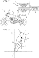
Fig. 1 is a view of the structure of an apparatus for determining a bank angle according to an embodiment of the present invention. -
Fig. 2 is a view explaining the relationship between accelerations of the body of a vehicle in the vertical and lateral directions and a bank angle of the body. -
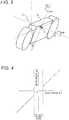
Fig. 3 is a view explaining the relationship between angular velocities of the body of a vehicle in the pitch and yaw directions and a bank angle of the body. -
Fig. 4 is a view illustrating a blind zone for a bank angle calculated by a second bank angle calculating section. -
Fig. 5 is a flow chart illustrating an example procedure for determining a bank angle by an apparatus for determining a bank angle according to an embodiment of the present invention. - The present invention will now be described based on the embodiment shown in the accompanying drawings . As shown in
Fig. 1 , an apparatus S for determining a bank angle according to the embodiment includes: anaccelerometer 1 for detecting an acceleration Gz of a body B of a vehicle V having a rider seat in the vertical direction (a vertical acceleration Gz of the body B) and an acceleration Gy of the body B in the lateral direction (a lateral acceleration Gy of the body B) ; and agyro sensor 2 for detecting an angular velocity Rθ of the body B in the pitch direction (a pitch angular velocity Rθ of the body B) and an angular velocity Rψ of the body B in the yaw direction (a yaw angular velocity Rψ of the body B); and an arithmetic unit C having a first bankangle calculating section 3, a second bank angle calculating section 4, and a bankangle selecting section 5. - The individual components of the apparatus will now be described in detail. In this example, the vehicle V is a motorcycle having a rider seat. As shown in
Fig. 1 , theaccelerometer 1 is disposed right under a rider seat B1 on the body B of the vehicle V for detecting the vertical acceleration Gz and the lateral acceleration Gy of the body B. Theaccelerometer 1 of this example may be a three-axis accelerometer that detects an acceleration of the body B in the longitudinal direction as well as the longitudinal acceleration Gz and the lateral acceleration Gy of the body B. - As shown in
Fig. 1 , thegyro sensor 2 is disposed right under the seat B1 on the body B, as in theaccelerometer 1, for detecting the pitch angular velocity Rθ and the yaw angular velocity Rψ of the body B. Thegyro sensor 2 of this example may be a three-axis gyro sensor that detects an angular velocity of the body B in the bank direction as well as the pitch angular velocity Rθ and the yaw angular velocity Rψ of the body B. - The arithmetic unit C is disposed under the seat B1 on the body B together with the
accelerometer 1 and thegyro sensor 2. When the arithmetic unit C is disposed near theaccelerometer 1 and thegyro sensor 2, the wiring can advantageously be short, however, the arithmetic unit C may be disposed at any place. The arithmetic unit C includes: a first bankangle calculating section 3 for calculating a bank angle ϕG of the body B based on the accelerations Gz and Gy; a second bank angle calculating section 4 for calculating a bank angle ϕJ of the body B based on the angular velocities Rθ and Rψ, and a bankangle selecting section 5 for selecting the larger bank angle from the bank angle ϕG and the bank angle ϕJ to determine a bank angle ϕe of the body B. - The first bank
angle calculating section 3 calculates the bank angle ϕG based on the vertical acceleration Gz and the lateral acceleration Gy of the body B detected by theaccelerometer 1. As shown inFig. 2 , when the body B is banked by a bank angle ϕ with respect to a vertical axis Ver with no centrifugal force, the resultant force of a vertical acceleration GOz and a lateral acceleration GOy of the body B on the center O of gravity of the body B corresponds to the gravitational acceleration g. If the accelerations Gz and Gy detected by theaccelerometer 1 are considered to correspond to the accelerations GOz and GOy on the center O of gravity, respectively, the following expression holds: ϕ=tan-1 (Gy/Gz). The first bankangle calculating section 3 calculates the bank angle ϕG based on the expression, ϕG=tan-1(Gy/Gz). When the body B is not subjected to a large centrifugal force, the bank angle ϕG calculated by the first bankangle calculating section 3 is substantially close to the actual bank angle of the body B. When the vehicle V turns, the centrifugal force increases with the increase in the velocity Vv of the vehicle V, which decreases the lateral acceleration Gy detected by theaccelerometer 1. Accordingly, as the velocity Vv of the vehicle V increases in a turn of the vehicle V, the bank angle ϕG calculated by the first bankangle calculating section 3 tends to be smaller than the actual bank angle. - The second bank angle calculating section 4 calculates the bank angle ϕJ based on the pitch angular velocity Rθ and the yaw angular velocity Rψ of the body B detected by the
gyro sensor 2. As shown inFig. 3 , when the body B is banked by the bank angle ϕ with respect to the vertical axis Ver, the relationship between the pitch angular velocity Rθ and the yaw angular velocity Rψ, and the bank angle ϕ can be expressed by the following expression: ϕ=sin-1(Rθ/Rψ). The second bank angle calculating section 4 calculates the bank angle ϕJ based on the expression, ϕJ=sin-1(Rθ/Rψ). The second bank angle calculating section 4 calculates the bank angle ϕJ based on the pitch angular velocity Rθ and the yaw angular velocity Rψ instead of integrating a bank angular velocity. Therefore, the second bank angle calculating section 4 can give the bank angle ϕJ that does not include an error arising from an integral drift. The bank angle ϕJ given by the second bank angle calculating section 4 is thus substantially close to the actual bank angle of the body B. - The bank
angle selecting section 5 selects the larger bank angle from the bank angle ϕG calculated by the first bankangle calculating section 3 and the bank angle ϕJ calculated by the second bank angle calculating section 4 to finally determine the bank angle ϕe. - As described above, the first bank
angle calculating section 3 calculates the bank angle ϕG based on the accelerations Gz and Gy detected by theaccelerometer 1. When the vehicle V turns at a high velocity Vv and is subjected to a large centrifugal force, the bank angle ϕG tends to be smaller than the actual bank angle of the body B. When the body B is not subjected to a large centrifugal force, however, the bank angle ϕG calculated by the first bankangle calculating section 3 based on the data from theaccelerometer 1 is substantially close to the actual bank angle. In other words, when the vehicle V runs at a low velocity or is at rest, the bank angle ϕG calculated based on the vertical acceleration Gz and the lateral acceleration Gy of the body B is substantially close to the actual bank angle of the body B. - On the other hand, the second bank angle calculating section 4 calculates the bank angle ϕJ based on the pitch angular velocity Rθ and the yaw angular velocity Rψ detected by the
gyro sensor 2. Therefore, the second bank angle calculating section 4 can give the bank angle ϕJ that is substantially close to the actual bank angle with little deviation. When the body B is banked slowly, however, thegyro sensor 2 cannot accurately detect the pitch angular velocity Rθ and the yaw angular velocity Rψ. In this case, the bank angle ϕJ calculated by the second bank angle calculating section 4 tends to be smaller than the actual bank angle. - If the larger bank angle is selected as the bank angle ϕe from the bank angle ϕG calculated by the first bank
angle calculating section 3 and the bank angle ϕJ calculated by the second bank angle calculating section ϕJ, the bank angle ϕe will substantially be close to the actual bank angle of the body B irrespective of the conditions of the vehicle V. - Since the
gyro sensor 2 is mounted in the body B of the vehicle V, which is subjected to the vibration of the engine, the pitch angular velocity Rθ and the yaw angular velocity Rψ are influenced by the components of the engine's vibration. Under such conditions, when a calculated bank angle ϕJ is near 0 degree, the value tends to be incorrect. As shown inFig. 4 , a blind zone may be set in a range including 0 degree for a bank angle ϕJ calculated by the second bank angle calculating section 4. In this case, when the calculated bank angle ϕJ is in the blind zone, the second bank angle calculating section 4 gives 0 degree as the value of the bank angle ϕJ. In the range in which the bank angle ϕJ calculated based on the data from thegyro sensor 2 tends to be incorrect, the bank angle ϕG calculated based on the data from theaccelerometer 1 tends to be selected. Accordingly, the bank angle ϕe closer to the actual bank angle of the body B is given. The blind zone may have any range, however, the blind zone should have a range in which a calculated bank angle ϕJ tends to be incorrect. - As described above, when the vehicle V runs at a low velocity Vv, the bank angle ϕG calculated by the first bank
angle calculating section 3 tends to be substantially close to the actual bank angle of the body B. As described above, when the body B is banked slowly, the bank angle ϕJ calculated by the second bank angle calculating section 4 tends to be smaller than the actual bank angle. In this respect, a threshold Vα may be set for the velocity Vv. In this case, whenever the velocity Vv is equal to or lower than the threshold Vα, the bankangle selecting section 5 selects the bank angle ϕG calculated by the first bankangle calculating section 3 based on the data from theaccelerometer 1. Accordingly, the bank angle ϕe closer to the actual bank angle of the body B is given. This method may be provided together with the above method using the blind zone for a bank angle ϕJ calculated by the second bank angle calculating section 4 in order to give 0 degree as the value of the bank angle ϕJ when the calculated bank angle ϕJ is in the blind zone. - The arithmetic unit C is a computer system having hardware resources including an amplifier for amplifying the signals from the
accelerometer 1 and thegyro sensor 2, a converter for converting analog signals to digital signals, a central prossesing unit (CPU), a memory such as a read only memory (ROM), a random access memory (RAM), a crystal oscillator, and bus lines connecting these components, all of which are not shown. The programs for processing various signals to determine the bank angle ϕe may be prestored in the ROM or other memory. - Since the arithmetic unit C is a known computer system, the arithmetic unit C can be integrated with an electronic control unit (ECU) in the vehicle V if the vehicle V has the ECU.
- The procedures took by the first bank
angle calculating sections 3, the second bank angle calculating section 4, and the bankangle selecting section 5 of the apparatus S for determining a bank angle will now be described with reference to the flow chart ofFig. 5 . First, the apparatus S for determining a bank angle detects the accelerations Gz and Gy with the accelerometer 1 (Step 101). Step 101 is thus a step of detecting accelerations. The apparatus S for determining a bank angle then detects the pitch angular velocity Rθ and the yaw angular velocity Rψ with the gyro sensor 2 (Step 102). Step 102 is thus a step of detecting angular velocities. The apparatus S for determining a bank angle then reads the accelerations Gz and Gy and calculates the bank angle cpG (Step 103). Step 103 is thus a step of calculating a first bank angle. The apparatus S for determining a bank angle then reads the pitch angular velocity Rθ and the yaw angular velocity Rψ and calculates the bank angle ϕJ (Step 104). Step 104 is thus a step of calculating a second bank angle. Finally, the apparatus S for determining a bank angle selects the larger bank angle from the bank angle ϕG and the bank angle ϕJ to determine the bank angle ϕe of the body B (Step 105). Step 105 is thus a step of selecting a bank angle. - The apparatus S for determining a bank angle repeats
Step 101 to Step 105 to continue to determine the bank angle ϕe of the body B. In this example, the method for determining a bank angle includesStep 101 to Step 105. - The determined bank angle ϕe may be used to control the damping force of a shock absorber in the vehicle V or be displayed on a monitor (not shown) for the rider of the vehicle V.
- As described above, the apparatus S for determining a bank angle selects the larger bank angle from the bank angle ϕG calculated based on the vertical and lateral accelerations Gz and Gy of the body B and the bank angle ϕJ calculated based on the pitch and yaw angular velocities Rθ and Rψ of the body B to determine the bank angle ϕe. Accordingly, the apparatus S for determining a bank angle can give the bank angle ϕe substantially close to the actual bank angle of the body B irrespective of the conditions of the vehicle V. According to the apparatus S and the method for determining a bank angle, the bank angle of the body B of the vehicle V can accurately be determined.
- In addition, the blind zone may be set in a certain range including 0 degree for a bank angle ϕJ calculated by the second bank angle calculating section 4. In this case, when the calculated bank angle ϕJ is in the blind zone, the second bank angle calculating section 4 may give 0 degree as the value of the bank angle ϕJ. In the range in which the bank angle ϕJ calculated based on the data from the
gyro sensor 2 tends to be incorrect, the apparatus S for determining a bank angle tends to select the bank angle ϕG calculated based on the data from theaccelerometer 1. Accordingly, the apparatus S for determining a bank angle can give the bank angle ϕe closer to the actual bank angle of the body B. - In addition, whenever the velocity Vv is equal to or lower than the threshold Vα, the bank angle ϕG calculated by the first bank
angle calculating section 3 based on the data from theaccelerometer 1 may be selected as the bank angle ϕe. Accordingly, the apparatus S can give the bank angle ϕe closer to the actual bank angle of the body B. - When the vehicle V has a rider seat and the
accelerometer 1 and thegyro sensor 2 are disposed under the seat B1 on the body B, the accelerations Gz and Gy and the angular velocities Rθ and Rψ can be detected near the center of gravity of the body B of the vehicle V with a rider. Accordingly, the apparatus S can give the bank angle ϕe closer to the actual bank angle of the body B. - This application claims a priority on Japanese Patent Application No.
2015-152963 filed on July 31, 2015
Claims (5)
- An apparatus for determining a bank angle, comprising:an accelerometer for detecting an acceleration of the body of a vehicle in the vertical direction and an acceleration of the body in the lateral direction;a gyro sensor for detecting an angular velocity of the body in the pitch direction and an angular velocity of the body in the yaw direction;a first bank angle calculating section for calculating a bank angle of the body based on the accelerations in the vertical and lateral directions detected by the accelerometer; anda second bank angle calculating section for calculating a bank angle of the body based on the angular velocities in the pitch and yaw directions detected by the gyro sensor,wherein the larger bank angle is selected from the bank angle calculated by the first bank angle calculating section and the bank angle calculated by the second bank angle calculating section to determine a bank angle of the body.
- The apparatus for determining a bank angle according to claim 1,
wherein the second bank angle calculating section gives 0 degree as the value of a calculated bank angle when the calculated bank angle is in a blind zone set in a range including 0 degree. - The apparatus for determining a bank angle according to claim 1,
wherein the bank angle calculated by the first bank angle calculating section is selected as the bank angle of the body when the velocity of the vehicle is equal to or lower than a threshold. - The apparatus for determining a bank angle according to claim 1,
wherein the vehicle has a rider seat, and
the accelerometer and the gyro sensor are disposed under the seat on the body. - A method for determining a bank angle, comprising:a step of detecting an acceleration of the body of a vehicle in the vertical direction and an acceleration of the body in the lateral direction;a step of detecting an angular velocity of the body in the pitch direction and an angular velocity of the body in the yaw direction;a step of calculating a first bank angle of the body based on the accelerations of the body in the vertical and lateral directions;a step of calculating a second bank angle of the body based on the angular velocities of the body in the pitch and yaw directions; anda step of selecting the larger bank angle from the first bank angle and the second bank angle to determine a bank angle of the body.
Applications Claiming Priority (2)
| Application Number | Priority Date | Filing Date | Title |
|---|---|---|---|
| JP2015152963A JP6502782B2 (en) | 2015-07-31 | 2015-07-31 | Bank angle detection device and bank angle detection method |
| PCT/JP2016/066378 WO2017022317A1 (en) | 2015-07-31 | 2016-06-02 | Banking angle detection device and banking angle detection method |
Publications (2)
| Publication Number | Publication Date |
|---|---|
| EP3330164A1 true EP3330164A1 (en) | 2018-06-06 |
| EP3330164A4 EP3330164A4 (en) | 2019-03-13 |
Family
ID=57944146
Family Applications (1)
| Application Number | Title | Priority Date | Filing Date |
|---|---|---|---|
| EP16832596.7A Withdrawn EP3330164A4 (en) | 2015-07-31 | 2016-06-02 | DEVICE FOR DETECTING THE ANGLE OF SINKS AND METHOD FOR DETECTING THE ANGLE OF SINKS |
Country Status (4)
| Country | Link |
|---|---|
| US (1) | US20180154968A1 (en) |
| EP (1) | EP3330164A4 (en) |
| JP (1) | JP6502782B2 (en) |
| WO (1) | WO2017022317A1 (en) |
Cited By (2)
| Publication number | Priority date | Publication date | Assignee | Title |
|---|---|---|---|---|
| JP2019003620A (en) * | 2017-05-10 | 2019-01-10 | ドゥカティ モーター ホールディング エセ.ペー.アー.DUCATI MOTOR HOLDING S.p.A. | Motorcycle equipped with device for detecting vehicle coming from behind |
| CN112601695A (en) * | 2018-07-13 | 2021-04-02 | 纬湃科技有限责任公司 | Learning angular position of a three-axis accelerometer integrated into an electronic control unit of a vehicle engine |
Families Citing this family (3)
| Publication number | Priority date | Publication date | Assignee | Title |
|---|---|---|---|---|
| JP7015161B2 (en) * | 2017-12-11 | 2022-02-02 | カワサキモータース株式会社 | Driving information storage method, driving information processing program and driving information storage device for lean vehicles |
| CN117730029A (en) * | 2021-07-29 | 2024-03-19 | 罗伯特·博世有限公司 | Movement control device, tilt vehicle and movement control method |
| CN114132415B (en) * | 2021-12-02 | 2023-06-02 | 南京快轮智能科技有限公司 | Control method for vehicle steering lamp |
Family Cites Families (20)
| Publication number | Priority date | Publication date | Assignee | Title |
|---|---|---|---|---|
| US6292759B1 (en) * | 1998-11-19 | 2001-09-18 | Delphi Technologies, Inc. | Vehicle attitude angle estimation using sensed signal blending |
| JP3504529B2 (en) * | 1999-03-31 | 2004-03-08 | 日本航空電子工業株式会社 | Gyro device for monitoring displacement of structures, ground, etc. |
| JP3886005B2 (en) * | 2002-09-26 | 2007-02-28 | Necトーキン株式会社 | Attitude angle detector |
| US7590481B2 (en) * | 2005-09-19 | 2009-09-15 | Ford Global Technologies, Llc | Integrated vehicle control system using dynamically determined vehicle conditions |
| DE102006061483B4 (en) * | 2006-02-22 | 2024-01-25 | Continental Automotive Technologies GmbH | Method and device for determining the roll angle of a motorcycle |
| JP4676001B2 (en) * | 2006-06-02 | 2011-04-27 | 三菱電機株式会社 | Inclination angle detection device for vehicle and rollover determination device using this device |
| JP4960929B2 (en) * | 2008-07-02 | 2012-06-27 | 壽夫 浅海 | Brake control device and behavior analysis device for motorcycle |
| JP2010058783A (en) * | 2008-08-08 | 2010-03-18 | Yamaha Motor Co Ltd | Body leaning control system, and saddle riding type vehicle having the same |
| DE102008043794A1 (en) * | 2008-11-17 | 2010-05-20 | Robert Bosch Gmbh | Method and device for determining the angle of inclination of a two-wheeled vehicle |
| JP5134527B2 (en) * | 2008-12-25 | 2013-01-30 | 川崎重工業株式会社 | Motorcycle bank angle detector and headlamp device |
| JP5361691B2 (en) * | 2009-12-11 | 2013-12-04 | 三菱電機株式会社 | Motorcycle angle estimation apparatus and method for motorcycle |
| JP5361692B2 (en) * | 2009-12-11 | 2013-12-04 | 三菱電機株式会社 | Motorcycle angle estimation apparatus and method for motorcycle |
| JP5393432B2 (en) * | 2009-12-21 | 2014-01-22 | ヤマハ発動機株式会社 | Roll angle estimation device and transport equipment |
| JP2011213336A (en) * | 2010-03-16 | 2011-10-27 | Protec:Kk | Motorcycle bank angle display system |
| JP5752379B2 (en) * | 2010-09-22 | 2015-07-22 | 川崎重工業株式会社 | Vehicle bank angle detector |
| US8548722B2 (en) * | 2011-08-12 | 2013-10-01 | Deere & Company | Tilt sensor and method for determining the tilt of a vehicle |
| JP2014000876A (en) * | 2012-06-18 | 2014-01-09 | Yamaha Motor Co Ltd | Sub-headlight unit and sub-headlight system for vehicles to turn in lean positions, and vehicle for turning in lean positions |
| JP5844331B2 (en) * | 2013-10-21 | 2016-01-13 | ヤマハ発動機株式会社 | Longitudinal force control device and saddle riding type vehicle equipped with the same |
| JP5914448B2 (en) * | 2013-11-01 | 2016-05-11 | ヤマハ発動機株式会社 | Saddle-type vehicle and wheel force acquisition device |
| WO2016037089A1 (en) * | 2014-09-04 | 2016-03-10 | Tagit Labs, Inc. | Methods and systems for automatic adverse event detection and alerting |
-
2015
- 2015-07-31 JP JP2015152963A patent/JP6502782B2/en not_active Expired - Fee Related
-
2016
- 2016-06-02 EP EP16832596.7A patent/EP3330164A4/en not_active Withdrawn
- 2016-06-02 WO PCT/JP2016/066378 patent/WO2017022317A1/en not_active Ceased
- 2016-06-02 US US15/570,455 patent/US20180154968A1/en not_active Abandoned
Cited By (2)
| Publication number | Priority date | Publication date | Assignee | Title |
|---|---|---|---|---|
| JP2019003620A (en) * | 2017-05-10 | 2019-01-10 | ドゥカティ モーター ホールディング エセ.ペー.アー.DUCATI MOTOR HOLDING S.p.A. | Motorcycle equipped with device for detecting vehicle coming from behind |
| CN112601695A (en) * | 2018-07-13 | 2021-04-02 | 纬湃科技有限责任公司 | Learning angular position of a three-axis accelerometer integrated into an electronic control unit of a vehicle engine |
Also Published As
| Publication number | Publication date |
|---|---|
| WO2017022317A1 (en) | 2017-02-09 |
| EP3330164A4 (en) | 2019-03-13 |
| JP6502782B2 (en) | 2019-04-17 |
| US20180154968A1 (en) | 2018-06-07 |
| JP2017030576A (en) | 2017-02-09 |
Similar Documents
| Publication | Publication Date | Title |
|---|---|---|
| EP3330164A1 (en) | Banking angle detection device and banking angle detection method | |
| US7359816B2 (en) | Sensor calibration method and apparatus | |
| US8332102B2 (en) | Vehicle safety system | |
| US8793098B2 (en) | Movement detection device, electronic device, movement detection method and computer readable medium | |
| US20090177425A1 (en) | Correction device for acceleration sensor, and output value correction method for acceleration sensor | |
| US8583324B2 (en) | Method and device for determining the angle of inclination of a two-wheeled vehicle | |
| JP2003531364A (en) | Apparatus for checking the validity of the fall judgment | |
| JP2006126148A (en) | Azimuth and orientation detection device | |
| US11685372B2 (en) | Processing unit and processing method for collision warning system, collision warning system, and motorcycle | |
| JP6604175B2 (en) | Pitch angular velocity correction value calculation device, attitude angle calculation device, and pitch angular velocity correction value calculation method | |
| JP6663006B2 (en) | Vehicle behavior detection device | |
| CN108657365A (en) | Control method, system and the electric bicycle of electric bicycle motor power | |
| JP6080695B2 (en) | Inclination angle detector | |
| US11142215B2 (en) | Processing unit and processing method for inter-vehicular distance warning system, inter-vehicular distance warning system, and motorcycle | |
| US20060206267A1 (en) | Methods and systems utilizing true airspeed to improve vertical velocity accuracy | |
| JP6632727B2 (en) | Angle measuring device | |
| JP2016199061A (en) | Inclination warning device | |
| JP6770181B2 (en) | Information processing device for saddle-riding vehicles and information processing method for saddle-riding vehicles | |
| JP2013178136A (en) | Mounting angle correction device | |
| JP2006300588A (en) | Tilt angle detection device for vehicle | |
| US9791277B2 (en) | Apparatus and method for measuring velocity of moving object in a navigation system | |
| JP2023016630A (en) | Acceleration detector and mounting angle detection method | |
| JP2006138758A (en) | Stable state determination device | |
| KR20240121935A (en) | Vehicle motion sickness reduction system using motion estimation and motion sickness reduction method | |
| JP5024250B2 (en) | Fall detection device, magnetic disk device, and portable electronic device |
Legal Events
| Date | Code | Title | Description |
|---|---|---|---|
| STAA | Information on the status of an ep patent application or granted ep patent |
Free format text: STATUS: THE INTERNATIONAL PUBLICATION HAS BEEN MADE |
|
| PUAI | Public reference made under article 153(3) epc to a published international application that has entered the european phase |
Free format text: ORIGINAL CODE: 0009012 |
|
| STAA | Information on the status of an ep patent application or granted ep patent |
Free format text: STATUS: REQUEST FOR EXAMINATION WAS MADE |
|
| 17P | Request for examination filed |
Effective date: 20180109 |
|
| AK | Designated contracting states |
Kind code of ref document: A1 Designated state(s): AL AT BE BG CH CY CZ DE DK EE ES FI FR GB GR HR HU IE IS IT LI LT LU LV MC MK MT NL NO PL PT RO RS SE SI SK SM TR |
|
| AX | Request for extension of the european patent |
Extension state: BA ME |
|
| DAV | Request for validation of the european patent (deleted) | ||
| DAX | Request for extension of the european patent (deleted) | ||
| A4 | Supplementary search report drawn up and despatched |
Effective date: 20190213 |
|
| RIC1 | Information provided on ipc code assigned before grant |
Ipc: B60W 40/112 20120101ALI20190207BHEP Ipc: B62J 99/00 20090101AFI20190207BHEP |
|
| STAA | Information on the status of an ep patent application or granted ep patent |
Free format text: STATUS: THE APPLICATION HAS BEEN WITHDRAWN |
|
| 18W | Application withdrawn |
Effective date: 20210806 |