EP3330161B1 - Vehicular steering assistance control device - Google Patents
Vehicular steering assistance control device Download PDFInfo
- Publication number
- EP3330161B1 EP3330161B1 EP16832753.4A EP16832753A EP3330161B1 EP 3330161 B1 EP3330161 B1 EP 3330161B1 EP 16832753 A EP16832753 A EP 16832753A EP 3330161 B1 EP3330161 B1 EP 3330161B1
- Authority
- EP
- European Patent Office
- Prior art keywords
- steering
- host vehicle
- driver
- traffic lane
- control device
- Prior art date
- Legal status (The legal status is an assumption and is not a legal conclusion. Google has not performed a legal analysis and makes no representation as to the accuracy of the status listed.)
- Active
Links
- 238000004364 calculation method Methods 0.000 claims description 13
- 230000008859 change Effects 0.000 claims description 6
- 238000004891 communication Methods 0.000 claims description 4
- 238000001514 detection method Methods 0.000 claims description 3
- 238000000034 method Methods 0.000 description 54
- 230000008569 process Effects 0.000 description 51
- 238000012508 change request Methods 0.000 description 10
- 238000012937 correction Methods 0.000 description 10
- 206010061876 Obstruction Diseases 0.000 description 7
- 238000010586 diagram Methods 0.000 description 6
- 230000000717 retained effect Effects 0.000 description 5
- 230000001133 acceleration Effects 0.000 description 3
- 238000013459 approach Methods 0.000 description 3
- 238000012986 modification Methods 0.000 description 3
- 230000004048 modification Effects 0.000 description 3
- XLYOFNOQVPJJNP-UHFFFAOYSA-N water Substances O XLYOFNOQVPJJNP-UHFFFAOYSA-N 0.000 description 3
- 238000006243 chemical reaction Methods 0.000 description 2
- 238000012423 maintenance Methods 0.000 description 2
- 230000007246 mechanism Effects 0.000 description 2
- 230000002093 peripheral effect Effects 0.000 description 2
- 238000012545 processing Methods 0.000 description 2
- 230000015556 catabolic process Effects 0.000 description 1
- 238000010276 construction Methods 0.000 description 1
- 238000007796 conventional method Methods 0.000 description 1
- 238000006731 degradation reaction Methods 0.000 description 1
- 230000001419 dependent effect Effects 0.000 description 1
- 238000013461 design Methods 0.000 description 1
- 230000000694 effects Effects 0.000 description 1
- 239000000446 fuel Substances 0.000 description 1
- 230000007274 generation of a signal involved in cell-cell signaling Effects 0.000 description 1
- 238000012544 monitoring process Methods 0.000 description 1
Images


Classifications
-
- B—PERFORMING OPERATIONS; TRANSPORTING
- B62—LAND VEHICLES FOR TRAVELLING OTHERWISE THAN ON RAILS
- B62D—MOTOR VEHICLES; TRAILERS
- B62D15/00—Steering not otherwise provided for
- B62D15/02—Steering position indicators ; Steering position determination; Steering aids
- B62D15/025—Active steering aids, e.g. helping the driver by actively influencing the steering system after environment evaluation
- B62D15/0255—Automatic changing of lane, e.g. for passing another vehicle
-
- B—PERFORMING OPERATIONS; TRANSPORTING
- B62—LAND VEHICLES FOR TRAVELLING OTHERWISE THAN ON RAILS
- B62D—MOTOR VEHICLES; TRAILERS
- B62D15/00—Steering not otherwise provided for
- B62D15/02—Steering position indicators ; Steering position determination; Steering aids
- B62D15/025—Active steering aids, e.g. helping the driver by actively influencing the steering system after environment evaluation
- B62D15/0265—Automatic obstacle avoidance by steering
-
- B—PERFORMING OPERATIONS; TRANSPORTING
- B62—LAND VEHICLES FOR TRAVELLING OTHERWISE THAN ON RAILS
- B62D—MOTOR VEHICLES; TRAILERS
- B62D6/00—Arrangements for automatically controlling steering depending on driving conditions sensed and responded to, e.g. control circuits
-
- B—PERFORMING OPERATIONS; TRANSPORTING
- B62—LAND VEHICLES FOR TRAVELLING OTHERWISE THAN ON RAILS
- B62D—MOTOR VEHICLES; TRAILERS
- B62D6/00—Arrangements for automatically controlling steering depending on driving conditions sensed and responded to, e.g. control circuits
- B62D6/02—Arrangements for automatically controlling steering depending on driving conditions sensed and responded to, e.g. control circuits responsive only to vehicle speed
-
- B—PERFORMING OPERATIONS; TRANSPORTING
- B62—LAND VEHICLES FOR TRAVELLING OTHERWISE THAN ON RAILS
- B62D—MOTOR VEHICLES; TRAILERS
- B62D6/00—Arrangements for automatically controlling steering depending on driving conditions sensed and responded to, e.g. control circuits
- B62D6/08—Arrangements for automatically controlling steering depending on driving conditions sensed and responded to, e.g. control circuits responsive only to driver input torque
-
- G—PHYSICS
- G08—SIGNALLING
- G08G—TRAFFIC CONTROL SYSTEMS
- G08G1/00—Traffic control systems for road vehicles
- G08G1/16—Anti-collision systems
- G08G1/166—Anti-collision systems for active traffic, e.g. moving vehicles, pedestrians, bikes
-
- G—PHYSICS
- G08—SIGNALLING
- G08G—TRAFFIC CONTROL SYSTEMS
- G08G1/00—Traffic control systems for road vehicles
- G08G1/16—Anti-collision systems
- G08G1/167—Driving aids for lane monitoring, lane changing, e.g. blind spot detection
Definitions
- the present invention relates to a vehicular steering assistance control device.
- a steering assistance control device including, as an additional function, the automatic steering operation of detecting the position and shape of a white line with devices, such as radar, a camera, a navigator, and an in-vehicle communication device, and applying steering torque to electric power steering to keep in a traffic lane.
- a calculation is typically made with, for example, PID control on the basis of the middle position in a traffic lane and the position and orientation of a host vehicle.
- the middle position in the traffic lane being a goal is offset to perform control (e.g., refer to PTL 1).
- the intervention of the steering of the driver may be determined in a case where a steering angle, a steering angle velocity, and the value of a steering torque sensor each have exceeded a driver steering intervention threshold value (e.g., refer to PTL 2 and PTL 3 below).
- US 2009/171533 A1 discloses a steering assist system with the features in the pre-characterizing portion of Claim 1.
- the driver intentionally travels in a position offset from the middle of the traffic lane to either the left or the right with the in-vehicle devices having difficulty in detecting the position, for example, in attempting to approach the opposite side to a side strip in the traffic lane to travel in order to avoid a splash of water occurring in a case where traveling on a puddle on the periphery of the side strip, the driver performs a steering operation toward the opposite side to the side strip.
- the steering assistance control device generates the steering torque in the opposite direction to the intention of the driver, the steering torque returning to the middle of the traffic lane.
- control of the steering assistance control device may be released in order to prevent the burden of the driver in the steering from increasing.
- the assistance with the control cannot be received, and thus there is a problem that convenience degrades.
- An object of the present invention is to provide a vehicular steering assistance control device capable of assisting in traveling in an appropriate position with steering assistance control in a case where a driver desirably and intentionally travels in a position offset from the middle of a traffic lane to either the left or the right.
- the present invention suggests the vehicular steering assistance control device defined in Claim 1. Further advantageous features are set out in the dependent claims.
- the device according to the present invention offsets the middle position of the traffic lane being a goal of the steering assistance control, to either the left or the right intended by the driver when the driver intentionally attempts to travel in the position offset from the middle of the traffic lane to either the left or the right in a case where the traveling is being performed with the steering assistance control performed.
- the vehicular steering assistance control device requires an algorithm for detecting that the driver intentionally attempts to travel in the position offset from the middle of the traffic lane to either the left or the right.
- the vehicular steering assistance control device can assist in traveling in the appropriate position with the steering assistance control in a case where the driver desirably and intentionally travels in the position offset from the middle of the traffic lane to either the left or the right.
- a vehicular steering assistance control device being one embodiment of the present invention, will be described below with reference to the drawings.
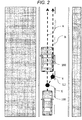
- the driver of a host vehicle 100 performs a steering operation to travel away from a side strip at a point X at which the driver has recognized occurrence of the puddle W1, and performs a steering operation to correct the travel route from a travel route A of the host vehicle in a case where traveling not away from the puddles W1, W2, and W3 to a travel route B of the host vehicle 100 in a case where traveling away from the puddles W1, W2, and W3.
- right steering at the point X and left steering at a point Y are performed to make an attempt to travel on a route in a position away from the side strip L1.
- FIG. 2 illustrates a state where a large vehicle is traveling ahead of the host vehicle.
- the driver monitors whether no oncoming vehicle or no obstruction is present in the oncoming lane, and may overtake at the right timing.
- the traveling may be performed intentionally close to a center line L2 in order to ease the monitoring.
- the travel route is corrected from a travel route A of the host vehicle to a travel route B close to the center line L2.
- right steering at a point X and left steering at a point Y are performed to make an attempt to travel in a position close to the center line L2.
- a driver continues to travel in the travel route A without overtaking, and travels right behind the vehicle 200 to reduce air resistance.
- the driver may select a method of improving fuel consumption.
- a driver may not overtake due to an awareness that the driver is weak at driving, so as to continue to travel in the travel route A.
- FIG. 3 illustrates a state where a vehicle is traveling, pulling alongside the host vehicle.
- the driver may desirably travel in a position close to the opposite direction to the vehicle 300 in a case where the vehicle 300 pulling alongside the host vehicle 100 is present.
- positioning is performed, at a point X at which the pulling alongside has been recognized, in the opposite direction to the vehicle pulling alongside, and thus left steering at the point X and right steering at a point Y are performed in order to correct the travel route from a travel route A of the host vehicle to a travel route B.
- the traveling may continue in the travel route A without the route correction to the travel route B.
- an appropriate travel pattern may vary due to a state where the detection is difficult to perform even with a sensor, such as a camera or radar, or the determination of the driver.
- FIG. 4 illustrates a waveform in steering torque performed by the driver and a waveform in steering torque performed by control before the present invention is applied, in a case where the appropriate travel pattern varies, as described above.
- the waveforms illustrated in FIG. 4 will be described with FIG. 1 , exemplarily.
- the vertical axis represents the value of steering torque. Left steering torque occurs when the value increases in the upper direction, and right steering torque occurs when the value increases in the lower direction. When the value of the origin is taken, it is indicated that no steering torque has occurred.
- the horizontal axis represents the position of the host vehicle 100 in the front and back direction.
- a waveform TD1 represents driver steering torque in steering assistance non-control
- a waveform TD2 represents the driver steering torque in steering assistance control
- a waveform TC2 represents control steering torque in the steering assistance control.
- the driver steering torque TD1 in the steering assistance non-control generates only the right steering torque at the point X and the left steering torque at the point Y illustrated in FIG. 1 , so as to set the yaw angle of the host vehicle to the traffic lane, to an angle of zero.
- the driver steering torque TD2 in the steering assistance control performs right steering at the point X due to the driver, similarly to the driver steering torque TD1. Note that, since the host vehicle separates from the travel route A in which traveling is performed in the middle of the traffic lane, the control attempts to return to the travel route A so that the steering assistance torque TC2 with the control is generated in the left direction.
- the driver increases the driver steering torque in the right direction to balance with the control steering torque, in order to travel in the travel route B. Since the control steering torque increases in the left direction in accordance with the increase above, the driver steering torque TD2 and the control steering torque TC2 continue to increase until the driver performs an operation of returning the steering back. After the operation of returning the steering back due to the driver, the driver performs left steering toward the point Y so that the yaw angle of the host vehicle to the traffic lane is set to an angle of zero. In this case, as the yaw angle of the orientation of the host vehicle to the traffic lane approaches the angle of zero, the driver steering torque TD2 attempts to vary to zero.
- the control steering torque TC2 makes an increase in the steering torque in the left direction.
- the driver since attempting to retain the yaw angle to the traffic lane at the angle of zero, the driver makes an increase in the steering torque in the right direction. Then, while traveling in the position, from the point Y, in which the traveling is performed with the yaw angle of the orientation of the host vehicle to the traffic lane, retained at the angle of zero, the driver must retain the steering torque constantly increasing in the right direction, resulting in fatigue due to the steering of the driver.
- the travel distance in the lateral direction and the travel distance in the front and back direction of the host vehicle 100 in this case are defined as Ym and Xm, respectively.
- a line indicating the middle position of the traffic lane is indicated with A in the figure
- the line extending in parallel to carriageway markings L1 and L2 and a line moved in parallel passing through the center of the host vehicle 100 is indicated with A' in the figure.
- the angle between the A in the figure and the orientation Vx of the host vehicle is defined as ⁇ d
- the angle between the A' in the figure and the orientation Vx of the host vehicle is defined as ⁇ d'. Since the A and the A' are parallel to each other, the ⁇ d and the ⁇ d' have the same value.
- the distance in the lateral direction from the line A indicating the middle position of the traffic lane to the center of the host vehicle is defined as Yi in the figure, and the value of Yi' moved in parallel is equal to that of the Yi.
- the width of the traffic lane is indicated with W.
- the vehicular steering assistance control device being the one embodiment of the present invention, will be described below with reference to the drawings.
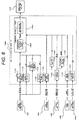
- FIG. 6 illustrates an exemplary control block diagram in a case where the present invention is applied.
- the host vehicle 100 acquires, as traffic lane information, a road shape with a carriageway marking or a curb in the travel route of the host vehicle, from an outside recognition device 200, such as a camera, connected to the vehicular steering assistance control device 1000, and then acquires, from the information, the curvature of the road 1 ⁇ R with a road curvature computation process 1100.
- the traffic lane width W of the roadway is acquired from the traffic lane information with a lane width computation process 1110.
- the lateral position Yi from the middle of the traffic lane from the traffic lane information and the traffic lane width W, with a lateral position computation process 1120.
- the yaw angle ⁇ d of the host vehicle to the traffic lane is acquired from the traffic information with a yaw angle computation process 1130.
- the velocity v of the host vehicle is acquired with host vehicle speed acquisition 1150. Furthermore, a variation in time is calculated to the velocity v that has been acquired, with an acceleration conversion process 1155 so that the acceleration a of the host vehicle is calculated.
- the steering angle ⁇ str of the host vehicle is acquired with steering angle acquisition 1160. Furthermore, a variation in time is calculated to the steering angle ⁇ str that has been acquired, with steering angle velocity conversion 1165 so that a steering angle velocity ⁇ str is calculated.
- the yaw rate ⁇ h of the host vehicle is acquired with yaw rate acquisition 1170.
- Steering amount computation 1400 is processed on the basis of the information that has been acquired above.
- the steering amount computation 1400 includes computation of a predicted goal for lateral position 1300 and steering control amount calculation 1500.
- a predicted goal lateral position Ytgt is first calculated with the computation of the predicted goal for lateral position 1300.
- a steering torque control amount TC is calculated with the steering control amount calculation 1500 on the basis of the predicted goal lateral position Ytgt, the host vehicle lateral position Yi, the yaw rate ⁇ h, the velocity of the host vehicle v, the yaw angle ⁇ d to the traffic lane, the yaw angle variation ⁇ h of the host vehicle, and the turning radius R.
- the vehicular steering assistance control device 1000 gives, as a command value, the steering torque control amount TC calculated with the steering amount computation 1400, to a steering actuator 900, such as electric power steering, so as to perform steering control of the host vehicle.
- FIG. 7 illustrates a flowchart indicating the details of the computation of the predicted goal for lateral position 1300. While the vehicle is traveling, the computation of the predicted goal for lateral position 1300 is repeatedly performed so that the steering control of the vehicle is performed. The computation of the predicted goal for lateral position 1300, first checks, as a premise, whether all the following conditions have been satisfied, with straight route stable travel determination 1310.
- the middle position (a zero value) in the traffic lane is set to the Ytgt.
- the lateral position being a goal is set to the middle in the traffic lane in a case where the unstable traveling is being performed.
- in-traffic-lane lateral position change request determination 1320 determines that a change request has been made, and if not, the in-traffic-lane lateral position change request determination 1320 determines that no change request has been made.
- the host vehicle lateral position Yi is set to a predicted goal lateral position temporary value Ytgt_tmp with process 1330.
- the processing proceeds to a process 1350 so that the value of the Ytgt_tmp is retained, the value being the last value.
- a goal lateral position correction process 1340 is performed to the Ytgt_tmp so that the Ytgt_tmp is set to the predicted goal lateral position.
- the in-traffic-lane lateral position change request determination 1320 switches the processing to detect a case where the driver steering torque is being generated to balance with the control steering torque after the point Y illustrated in FIG. 4 , namely, whether the driver intentionally attempts to travel in a position close to either the left or the right from the middle of the traffic lane. In a case where deviation has been temporarily made from the middle of the traffic lane, the goal position is not changed so that the goal lateral position can be naturally switched.
- FIG. 8 illustrates a flowchart expressing the details of the goal lateral position correction process 1340.
- a change rate limit process is performed to the Ytgt_tmp with a change rate limit process 1341 so that Ytgt_ratelim is calculated.
- the change rate limit value in this case, is set to a large value so that the driver is prevented from being given a sense of discomfort due to a rapid change of the TC based on a rapid change of the Ytgt and the fatigue of the driver can be reduced as much as possible.
- the value is tuned in accordance with the vehicle and the characteristics of the electric power steering.
- the value is dynamically switchable to be small when the velocity is high and to be large when the velocity is low, in accordance with the current velocity of the host vehicle.
- a goal lateral position upper limit value is calculated with a process 1342.
- the goal lateral position upper limit value is set to a value in which a safety maintenance distance margin from the carriageway marking, is subtracted from the value of the traffic lane width divided by two.
- the safety maintenance distance margin from the carriageway marking is calculated in inverse proportion to the velocity v of the host vehicle.
- sign inversion is performed to the goal lateral position upper limit value calculated with the process 1342 so that the goal lateral position upper limit value is set to a goal lateral position lower limit value.
- a limit process is performed to the Ytgt_ratelim calculated with the process 1341, with the goal lateral position upper limit value and the goal lateral position lower limit value acquired with the process 1342 and the process 1343, respectively, so that Ytgt_lim is acquired.
- the Ytgt_lim is set as a result of the goal lateral position correction process 1340, with a process 1345.
- FIG. 9 illustrates a flowchart expressing the details of the steering torque control amount calculation 1500.
- the steering torque control amount calculation 1500 estimates in which position the host vehicle 100 is traveling when control target time th [s] has passed. Therefore, the ⁇ h is multiplied by the th with a process 1501 so that the relative yaw angle ⁇ h of the host vehicle after the control target time to the current host vehicle, is calculated. Next, the v is multiplied by the th with a process 1502 so that the travel distance lh is acquired at the control target time.
- the lh calculated with the process 1501 is divided by the ⁇ h calculated with the process 1502 in a process 1503 so that the turning radius R of the host vehicle is acquired.
- Ys Xm ⁇ tan ⁇ d ⁇ Yi
- gain control is performed to a proportional term TCp, an integral term TCi, and a differential term TCd in PID control to make the respective calculations thereof. Then, the sum total is calculated with a process 1524 so that the control steering torque TC is calculated.
- FIG. 10 illustrates a waveform in the steering torque by the driver and a waveform in the steering torque by the steering assistance control when the present invention has been applied in the first embodiment.
- a waveform TD1 represents the driver steering torque in the steering assistance non-control
- a waveform TD2 represents the driver steering torque in the steering assistance control
- a waveform TC2' represents the control steering torque in the steering assistance control.
- the steering assistance torque TC2' in the application of the present invention the steering assistance torque gradually returns to zero in a case where the traveling starts in parallel to the carriageway marking after the pass of the point Y, in comparison to the control steering torque TC2 before the application of the present invention, illustrated in FIG. 4 . Therefore, the driver steering torque also becomes zero.
- FIG. 11 illustrates a modification of the control block diagram of FIG. 6 described in the first embodiment.
- a host vehicle 100 includes a driver switch 700 for reflecting in which position a driver desirably travels in a roadway, provided together with, for example, steering and an indicator lever, to the configuration described in the first embodiment, so as to acquire switch information Sw from the driver with switch operation acquisition 1190.
- the Sw has five types of values including a current position, a right move, a left move, a middle move, and no operation, in accordance with a switch operation of the driver.
- the Sw that has been acquired, is used for computation of a predicted goal for lateral position, and the flowchart illustrated in FIG. 7 is modified to a flowchart of the computation of the predicted goal for lateral position, with the switch operation, illustrated in FIG. 12 .
- the conditions of the in-traffic-lane lateral position change request determination 1320 are replaced with driver switch determination 1321 in order to make a switch between processes performed with the values of the Sw.
- a host vehicle lateral position Yi is set to a predicted goal lateral position temporary value Ytgt_tmp so that traveling is performed remaining in the current position.
- a lateral travel amount offset YOffset is subtracted from the last goal lateral position to acquire the predicted goal lateral position temporary value Ytgt_tmp so that the position being the goal is changed in the right direction.
- the lateral travel amount offset YOffset is added to the last goal lateral position to acquire the predicted goal lateral position temporary value Ytgt_tmp so that the position being the goal is changed in the left direction.
- the middle position in the traffic lane is set to the predicted goal lateral position temporary value Ytgt_tmp so that the predicted goal lateral position moved in the right and the left with the switch operations of the right move and the left move, respectively, can be returned to the middle.
- the value of the Ytgt_tmp is retained so as to be the value for the move to the right position if the last switch operation is the right move or the value for the move to the left position if the last switch operation is the left move.
- the predicted goal lateral position can be changed even when no switch is operated.
- inconvenience in operating the switch can be reduced and additionally an intention of directly switching the goal lateral position desirably, can be given.
- the determination of the driver switch determination 1321 has priority over the determination 1320 so that the intention due to the switch operation having the intention of switching the goal lateral position, reflected more strongly from the prediction of the driver, can be reflected in the control.
- a display device 800 is provided to the control block diagram of FIG. 6 described in the first embodiment, the display device 800 being given Disp generated and transmitted with display signal generation 1600 on the basis of the Ytgt generated by the computation process of the predicted goal for lateral position 1300, to issue an notification to the driver.
- the display device is preferably provided in order for the driver to determine whether the control device has received the switch operation or has not received the switch operation due to the influence of disturbance that the driver does not intend.
- the host vehicle 100 includes either a communication device 210 or GPS 220 or both thereof to the configuration described in the first embodiment, and is added with a mechanism capable of generating the position, orientation, and geographic information on the host vehicle from each piece of information with geographic information matching 250 together with information acquired from an outside recognition device 200. Generating the position, orientation, and geographic information on the host vehicle from a plurality of information sources, improves the precision of the information used for the control so that the control appropriate to a larger number of patterns can be performed.
- a curve in a region being a blind spot of a camera or radar, that cannot be detected by the outside recognition device 200 independently, is detected early to make straight route stable travel determination 1310 early determine instability on the basis of the conditions. Then, the lateral position of the host vehicle in the traffic lane is adjusted to return to the middle of the traffic lane before an approach to the curve so that safety can improve. Even under a state where the camera cannot detect the carriageway marking due to a snow cover or aged degradation, the middle position of the traffic lane can be acquired from the geographic information so that the control can be performed.
- a road classification acquisition process 1105 is additionally provided so that road information RoadInfo is acquired, such as a distance to a right/left-turn route, a travel upper limit speed for the road, whether the road is an accident-prone point, a grade crossing, a no-passing road, a one-way route, or a superhighway.
- RoadInfo is acquired, such as a distance to a right/left-turn route, a travel upper limit speed for the road, whether the road is an accident-prone point, a grade crossing, a no-passing road, a one-way route, or a superhighway.
- the RoadInfo that has been acquired is used for the process 1342 in the goal lateral position correction process illustrated in FIG. 8 , and either offset addition or gain multiplication or both thereof appropriate to the value of the RoadInfo are performed in calculating the safety distance margin from the carriageway marking.
- the safety distance margin from the carriageway marking is set to a value approximate to zero so that the traveling can be performed in a more free position in the roadway.
- the safety distance margin from the center line is increased to prevent crossing of the center line from being performed wrongly.
- the distance from the center line to the host vehicle is increased to allow leeway so that safety can improve.
- the host vehicle 100 acquires obstruction information with peripheral obstruction detection 260, with information acquired from the communication device 210 and detected object information from the outside recognition device 200, to the configuration described in the first embodiment.
- the obstruction information that has been acquired is converted into ObjectInfo with obstruction information acquisition 1140.
- the ObjectInfo includes the type, travel direction, travel speed, and relative position of the obstruction to the host vehicle 100.
- the ObjectInfo is used for the process 1342 in the goal lateral position correction process illustrated in FIG. 8 , and either offset addition or gain multiplication or both thereof appropriate to the value of each piece of information in the ObjectInfo are performed in calculating the safety distance margin from the carriageway marking.
- the safety distance margin from the carriageway marking is increased to • improve safety.
- the safety distance margin from the carriageway marking is increased so that safety can improve.
- a part of the mechanisms or the entirety is selected and mounted on the basis of the performance of each sensor, the design concept of the vehicle, and a cost conception stage so that functions appropriate to the preference of the driver, can be provided.
Landscapes
- Engineering & Computer Science (AREA)
- Chemical & Material Sciences (AREA)
- Combustion & Propulsion (AREA)
- Transportation (AREA)
- Mechanical Engineering (AREA)
- Physics & Mathematics (AREA)
- General Physics & Mathematics (AREA)
- Steering Control In Accordance With Driving Conditions (AREA)
- Traffic Control Systems (AREA)
- Control Of Driving Devices And Active Controlling Of Vehicle (AREA)
Description
- The present invention relates to a vehicular steering assistance control device.
- In order to reduce the burden of a driver in driving a vehicle, there is a steering assistance control device including, as an additional function, the automatic steering operation of detecting the position and shape of a white line with devices, such as radar, a camera, a navigator, and an in-vehicle communication device, and applying steering torque to electric power steering to keep in a traffic lane.
- For the calculation of the steering torque in the steering assistance control device, a calculation is typically made with, for example, PID control on the basis of the middle position in a traffic lane and the position and orientation of a host vehicle.
- The following technique in the steering assistance control device has been known. In accordance with a previously detectable road environment, such as the shape of a road or construction, with in-vehicle devices, such as GPS and a camera, the middle position in the traffic lane being a goal is offset to perform control (e.g., refer to PTL 1).
- In order to prioritize steering of the driver in the steering assistance control device, there is a technique of releasing steering assistance control in a case where intervention of the steering of the driver has been detected. The intervention of the steering of the driver may be determined in a case where a steering angle, a steering angle velocity, and the value of a steering torque sensor each have exceeded a driver steering intervention threshold value (e.g., refer to PTL 2 and PTL 3 below).
-
- PTL 1: Japanese Patent Laid-Open No.
2003-44137 - PTL 2: Japanese Patent Laid-Open No.
H10-203394 - PTL 3: Japanese Patent Laid-Open No.
Hll-286280 -
US 2009/171533 A1 discloses a steering assist system with the features in the pre-characterizing portion ofClaim 1. - However, according to the conventional technique, in a case where the driver intentionally travels in a position offset from the middle of the traffic lane to either the left or the right with the in-vehicle devices having difficulty in detecting the position, for example, in attempting to approach the opposite side to a side strip in the traffic lane to travel in order to avoid a splash of water occurring in a case where traveling on a puddle on the periphery of the side strip, the driver performs a steering operation toward the opposite side to the side strip. At this time, the steering assistance control device generates the steering torque in the opposite direction to the intention of the driver, the steering torque returning to the middle of the traffic lane. Thus, there is a problem that the burden of the driver rather increases.
- Alternatively, the control of the steering assistance control device may be released in order to prevent the burden of the driver in the steering from increasing. However, the assistance with the control cannot be received, and thus there is a problem that convenience degrades.
- An object of the present invention is to provide a vehicular steering assistance control device capable of assisting in traveling in an appropriate position with steering assistance control in a case where a driver desirably and intentionally travels in a position offset from the middle of a traffic lane to either the left or the right.
- In order to solve the above problems, the present invention suggests the vehicular steering assistance control device defined in
Claim 1. Further advantageous features are set out in the dependent claims. The device according to the present invention offsets the middle position of the traffic lane being a goal of the steering assistance control, to either the left or the right intended by the driver when the driver intentionally attempts to travel in the position offset from the middle of the traffic lane to either the left or the right in a case where the traveling is being performed with the steering assistance control performed. - The vehicular steering assistance control device requires an algorithm for detecting that the driver intentionally attempts to travel in the position offset from the middle of the traffic lane to either the left or the right.
- The vehicular steering assistance control device according to the present invention, can assist in traveling in the appropriate position with the steering assistance control in a case where the driver desirably and intentionally travels in the position offset from the middle of the traffic lane to either the left or the right.
-
- [
FIG. 1] FIG. 1 illustrates a state where a puddle has occurred on the side of a side strip on a travel route of a host vehicle. - [
FIG. 2] FIG. 2 illustrates a state where a large vehicle is traveling ahead of the host vehicle. - [
FIG. 3] FIG. 3 illustrates a state where a vehicle is traveling, pulling alongside the host vehicle. - [
FIG. 4] FIG. 4 illustrates a waveform in steering torque performed by a driver and a waveform in steering torque performed by control before the present invention is applied. - [
FIG. 5] FIG. 5 is a diagram illustrating each symbol for describing the present embodiment. - [
FIG. 6] FIG. 6 is an exemplary control block diagram in a case where the present invention is applied. - [
FIG. 7] FIG. 7 is a flowchart of a computation process of a predicted goal for lateral position. - [
FIG. 8] FIG. 8 is a flowchart of a goal lateral position correction process. - [
FIG. 9] FIG. 9 is a flowchart of steering torque control amount calculation. - [
FIG. 10] FIG. 10 illustrates a waveform in the steering torque performed by the driver and a waveform in the steering torque performed by the control in the application of the present invention. - [
FIG. 11] FIG. 11 is a second exemplary control block diagram in a case where the present invention is applied. - [
FIG. 12] FIG. 12 is a flowchart of the computation process of the predicted goal for lateral position, modified with a driver switch. - [
FIG. 13] FIG. 13 is a flowchart of the computation process of the predicted goal for lateral position, including driver switch conditions combined. - A vehicular steering assistance control device being one embodiment of the present invention, will be described below with reference to the drawings.
- As illustrated in
FIG. 1 , in order to prevent a pedestrian P from being splashed with water by swirling the water when traveling on puddles, the driver of ahost vehicle 100 performs a steering operation to travel away from a side strip at a point X at which the driver has recognized occurrence of the puddle W1, and performs a steering operation to correct the travel route from a travel route A of the host vehicle in a case where traveling not away from the puddles W1, W2, and W3 to a travel route B of thehost vehicle 100 in a case where traveling away from the puddles W1, W2, and W3. At this time, right steering at the point X and left steering at a point Y are performed to make an attempt to travel on a route in a position away from the side strip L1. -
FIG. 2 illustrates a state where a large vehicle is traveling ahead of the host vehicle. In a case where thevehicle 200 traveling ahead of thehost vehicle 100 is traveling at a low speed, the driver monitors whether no oncoming vehicle or no obstruction is present in the oncoming lane, and may overtake at the right timing. At this time, in case where the visibility of the driver has been blocked by thevehicle 200 traveling ahead, the traveling may be performed intentionally close to a center line L2 in order to ease the monitoring. In this case, at the timing at which the driver decides to overtake, the travel route is corrected from a travel route A of the host vehicle to a travel route B close to the center line L2. Thus, right steering at a point X and left steering at a point Y are performed to make an attempt to travel in a position close to the center line L2. Note that, a driver continues to travel in the travel route A without overtaking, and travels right behind thevehicle 200 to reduce air resistance. Thus, the driver may select a method of improving fuel consumption. In addition, a driver may not overtake due to an awareness that the driver is weak at driving, so as to continue to travel in the travel route A. -
FIG. 3 illustrates a state where a vehicle is traveling, pulling alongside the host vehicle. The driver may desirably travel in a position close to the opposite direction to thevehicle 300 in a case where thevehicle 300 pulling alongside thehost vehicle 100 is present. In that case, positioning is performed, at a point X at which the pulling alongside has been recognized, in the opposite direction to the vehicle pulling alongside, and thus left steering at the point X and right steering at a point Y are performed in order to correct the travel route from a travel route A of the host vehicle to a travel route B. Note that, depending on peripheral environments, in a case where a bicycle C is traveling on the side of a side strip L1 or in a case where it can be determined that the pulling alongside of thevehicle 300 is in a temporary state in order to avoid an obstruction, the traveling may continue in the travel route A without the route correction to the travel route B. - As described above, an appropriate travel pattern may vary due to a state where the detection is difficult to perform even with a sensor, such as a camera or radar, or the determination of the driver. Examples of the case where the appropriate travel pattern varies, include the following states in addition to the above.
-
- A case where the host vehicle travels on the left in the traffic lane in order to inhibit, for example, a motorcycle approaching from the backward of the host vehicle, from overtaking on the left.
- A case where the host vehicle travels on the right in the traffic lane in order to cause, for example, a motorcycle approaching from the backward of the hose vehicle to easily overtake.
- A case where the host vehicle travels in a position close to the center line in traveling through a blind intersection.
- A case where the host vehicle desirably travels taking a position opposite to an oncoming vehicle since the oncoming vehicle has the headlights on high beam.
- A case where the host vehicle desirably travels close to the opposite side to a congested route, being careful of rushing-out in traveling next to the congested route.
- A case where the host vehicle desirably keeps a distance from the oncoming lane side when traveling through a location at which a strong crosswind blows, such as on a bridge.
-
FIG. 4 illustrates a waveform in steering torque performed by the driver and a waveform in steering torque performed by control before the present invention is applied, in a case where the appropriate travel pattern varies, as described above. The waveforms illustrated inFIG. 4 will be described withFIG. 1 , exemplarily. In the graph illustrated inFIG. 4 , the vertical axis represents the value of steering torque. Left steering torque occurs when the value increases in the upper direction, and right steering torque occurs when the value increases in the lower direction. When the value of the origin is taken, it is indicated that no steering torque has occurred. The horizontal axis represents the position of thehost vehicle 100 in the front and back direction. The point X and the point Y illustrated inFIG. 1 agree with X on the horizontal axis of the graph and Y on the horizontal axis of the graph, respectively. InFIG. 4 , a waveform TD1 represents driver steering torque in steering assistance non-control, a waveform TD2 represents the driver steering torque in steering assistance control, and a waveform TC2 represents control steering torque in the steering assistance control. - The driver steering torque TD1 in the steering assistance non-control, generates only the right steering torque at the point X and the left steering torque at the point Y illustrated in
FIG. 1 , so as to set the yaw angle of the host vehicle to the traffic lane, to an angle of zero. In comparison to the driver steering torque TD1 in the steering assistance non-control, the driver steering torque TD2 in the steering assistance control, performs right steering at the point X due to the driver, similarly to the driver steering torque TD1. Note that, since the host vehicle separates from the travel route A in which traveling is performed in the middle of the traffic lane, the control attempts to return to the travel route A so that the steering assistance torque TC2 with the control is generated in the left direction. In contrast, the driver increases the driver steering torque in the right direction to balance with the control steering torque, in order to travel in the travel route B. Since the control steering torque increases in the left direction in accordance with the increase above, the driver steering torque TD2 and the control steering torque TC2 continue to increase until the driver performs an operation of returning the steering back. After the operation of returning the steering back due to the driver, the driver performs left steering toward the point Y so that the yaw angle of the host vehicle to the traffic lane is set to an angle of zero. In this case, as the yaw angle of the orientation of the host vehicle to the traffic lane approaches the angle of zero, the driver steering torque TD2 attempts to vary to zero. However, it is determined that the travel route of the host vehicle does not lead to the middle of the traffic lane, and thus the control steering torque TC2 makes an increase in the steering torque in the left direction. Note that, since attempting to retain the yaw angle to the traffic lane at the angle of zero, the driver makes an increase in the steering torque in the right direction. Then, while traveling in the position, from the point Y, in which the traveling is performed with the yaw angle of the orientation of the host vehicle to the traffic lane, retained at the angle of zero, the driver must retain the steering torque constantly increasing in the right direction, resulting in fatigue due to the steering of the driver. - Symbols indicating the relationship between the
host vehicle 100 and the traffic lane, will be described withFIG. 5 in the description of the embodiment below. When the current velocity and yaw rate of thehost vehicle 100 are defined as v [m/s] and ωh [rad/s], respectively, and the travel distance of the host vehicle with the velocity and a steering angle retained constant after t in time, is defined as lh in the figure, the following expression is satisfied:
- When the yaw angle variation of the host vehicle after the t in time is defined as θh in the figure, the following expression is satisfied:

- The turning radius of the
host vehicle 100 in this case defined as R in the figure, is calculated by the following formula:
- The travel distance in the lateral direction and the travel distance in the front and back direction of the
host vehicle 100 in this case are defined as Ym and Xm, respectively. - A line indicating the middle position of the traffic lane, is indicated with A in the figure, the line extending in parallel to carriageway markings L1 and L2, and a line moved in parallel passing through the center of the
host vehicle 100, is indicated with A' in the figure. The angle between the A in the figure and the orientation Vx of the host vehicle, is defined as θd, and the angle between the A' in the figure and the orientation Vx of the host vehicle, is defined as θd'. Since the A and the A' are parallel to each other, the θd and the θd' have the same value. The distance in the lateral direction from the line A indicating the middle position of the traffic lane to the center of the host vehicle, is defined as Yi in the figure, and the value of Yi' moved in parallel is equal to that of the Yi. - In a case where the traveling has been performed for the t in time with the constant velocity and the constant steering angle retained with the current velocity and yaw rate of the
host vehicle 100 defined as the v [m/s] and the ωh [rad/s], respectively, a move is made from the line A indicating the middle position of the traffic lane through a distance of the Ym + Ys in the lateral direction from the initial position and initial orientation of thehost vehicle 100. In this case, the travel distance offset Ys in the lateral direction from the middle position, added to the travel distance Ym in the lateral direction of thehost vehicle 100 from the line A indicating the middle position, is calculated by the following formula.
- The width of the traffic lane is indicated with W.
- The vehicular steering assistance control device being the one embodiment of the present invention, will be described below with reference to the drawings.
-
FIG. 6 illustrates an exemplary control block diagram in a case where the present invention is applied. - The
host vehicle 100 acquires, as traffic lane information, a road shape with a carriageway marking or a curb in the travel route of the host vehicle, from anoutside recognition device 200, such as a camera, connected to the vehicular steeringassistance control device 1000, and then acquires, from the information, the curvature of theroad 1 ÷ R with a roadcurvature computation process 1100. Similarly, the traffic lane width W of the roadway is acquired from the traffic lane information with a lanewidth computation process 1110. The lateral position Yi from the middle of the traffic lane from the traffic lane information and the traffic lane width W, with a lateralposition computation process 1120. The yaw angle θd of the host vehicle to the traffic lane, is acquired from the traffic information with a yawangle computation process 1130. - On the basis of a vehicle speed sensor value acquired from a
vehicle speed sensor 300 connected to the vehicular steeringassistance control device 1000, the velocity v of the host vehicle is acquired with hostvehicle speed acquisition 1150. Furthermore, a variation in time is calculated to the velocity v that has been acquired, with anacceleration conversion process 1155 so that the acceleration a of the host vehicle is calculated. - On the basis of a steering angle sensor value acquired from a
steering angle sensor 400 connected to the vehicular steeringassistance control device 1000, the steering angle θstr of the host vehicle is acquired withsteering angle acquisition 1160. Furthermore, a variation in time is calculated to the steering angle θstr that has been acquired, with steeringangle velocity conversion 1165 so that a steering angle velocity θstr is calculated. On the basis of a yaw rate sensor value acquired from ayaw rate sensor 500 connected to the vehicular steeringassistance control device 1000, the yaw rate ωh of the host vehicle is acquired withyaw rate acquisition 1170. - On the basis of a steering torque sensor value acquired from a
steering torque sensor 600 connected to the vehicular steeringassistance control device 1000, driver steering torque TD is acquired withsteering torque acquisition 1180.Steering amount computation 1400 is processed on the basis of the information that has been acquired above. Thesteering amount computation 1400 includes computation of a predicted goal forlateral position 1300 and steeringcontrol amount calculation 1500. A predicted goal lateral position Ytgt is first calculated with the computation of the predicted goal forlateral position 1300. - Furthermore, a steering torque control amount TC is calculated with the steering
control amount calculation 1500 on the basis of the predicted goal lateral position Ytgt, the host vehicle lateral position Yi, the yaw rate ωh, the velocity of the host vehicle v, the yaw angle θd to the traffic lane, the yaw angle variation θh of the host vehicle, and the turning radius R. - The vehicular steering
assistance control device 1000 gives, as a command value, the steering torque control amount TC calculated with thesteering amount computation 1400, to asteering actuator 900, such as electric power steering, so as to perform steering control of the host vehicle. -
FIG. 7 illustrates a flowchart indicating the details of the computation of the predicted goal forlateral position 1300. While the vehicle is traveling, the computation of the predicted goal forlateral position 1300 is repeatedly performed so that the steering control of the vehicle is performed. The computation of the predicted goal forlateral position 1300, first checks, as a premise, whether all the following conditions have been satisfied, with straight routestable travel determination 1310. -
- The absolute value of the (1 ÷ R) is less than a straight route stable travel threshold value.
- The absolute value of the θstr is less than a straight route stable travel threshold value.
- The absolute value of the ωstr is less than a straight route stable travel threshold value.
- The absolute value of the TD is less than a rapid steering determination threshold value.
- The absolute value of the θd is less than a stable travel threshold value.
- The absolute value of the Yi is a stable travel threshold value or more.
- The v is a control threshold value or more.
- The v is less than a control upper limit threshold value.
- No failure in a related device is detected.
- In a case where instability is determined as a result of the straight
stable travel determination 1310, the middle position (a zero value) in the traffic lane is set to the Ytgt. With this arrangement, the lateral position being a goal is set to the middle in the traffic lane in a case where the unstable traveling is being performed. Thus, stability is ensured to prevent deviation from the traffic lane by disturbance due to, for example, a step on the road in traveling in a position close to either the left or the right in the traffic lane in a case where the traveling is being performed without the stability ensured. - In a case where stability is determined with the straight route
stable travel determination 1310, if a certain period of time has passed with all the following conditions satisfied, in-traffic-lane lateral positionchange request determination 1320 determines that a change request has been made, and if not, the in-traffic-lane lateral positionchange request determination 1320 determines that no change request has been made. -
- The absolute value of (the TD - the TC) < a driver torque comparable threshold value.
- The absolute value of the θd is less than a straight travel threshold value.
- In a case where the in-traffic-lane lateral position
change request determination 1320 determines that a lateral position change request has been made, the host vehicle lateral position Yi is set to a predicted goal lateral position temporary value Ytgt_tmp withprocess 1330. In a case where the in-traffic-lane lateral positionchange request determination 1320 determines that no lateral position change request has been made, the processing proceeds to aprocess 1350 so that the value of the Ytgt_tmp is retained, the value being the last value. After that, a goal lateralposition correction process 1340 is performed to the Ytgt_tmp so that the Ytgt_tmp is set to the predicted goal lateral position. - The in-traffic-lane lateral position
change request determination 1320 switches the processing to detect a case where the driver steering torque is being generated to balance with the control steering torque after the point Y illustrated inFIG. 4 , namely, whether the driver intentionally attempts to travel in a position close to either the left or the right from the middle of the traffic lane. In a case where deviation has been temporarily made from the middle of the traffic lane, the goal position is not changed so that the goal lateral position can be naturally switched. -
FIG. 8 illustrates a flowchart expressing the details of the goal lateralposition correction process 1340. In the goal lateralposition correction process 1340, a change rate limit process is performed to the Ytgt_tmp with a changerate limit process 1341 so that Ytgt_ratelim is calculated. The change rate limit value in this case, is set to a large value so that the driver is prevented from being given a sense of discomfort due to a rapid change of the TC based on a rapid change of the Ytgt and the fatigue of the driver can be reduced as much as possible. The value is tuned in accordance with the vehicle and the characteristics of the electric power steering. Desirably, the value is dynamically switchable to be small when the velocity is high and to be large when the velocity is low, in accordance with the current velocity of the host vehicle. Next, a goal lateral position upper limit value is calculated with aprocess 1342. The goal lateral position upper limit value is set to a value in which a safety maintenance distance margin from the carriageway marking, is subtracted from the value of the traffic lane width divided by two. The safety maintenance distance margin from the carriageway marking, is calculated in inverse proportion to the velocity v of the host vehicle. In aprocess 1343, sign inversion is performed to the goal lateral position upper limit value calculated with theprocess 1342 so that the goal lateral position upper limit value is set to a goal lateral position lower limit value. After that, in aprocess 1344, a limit process is performed to the Ytgt_ratelim calculated with theprocess 1341, with the goal lateral position upper limit value and the goal lateral position lower limit value acquired with theprocess 1342 and theprocess 1343, respectively, so that Ytgt_lim is acquired. Finally, the Ytgt_lim is set as a result of the goal lateralposition correction process 1340, with aprocess 1345. With this arrangement, even when unexpected steering occurs, an extension can be given to the control until the deviation from the traffic lane or the time in which the driver can intervene, and thus safety improves. -
FIG. 9 illustrates a flowchart expressing the details of the steering torquecontrol amount calculation 1500. The steering torquecontrol amount calculation 1500 estimates in which position thehost vehicle 100 is traveling when control target time th [s] has passed. Therefore, the ωh is multiplied by the th with aprocess 1501 so that the relative yaw angle θh of the host vehicle after the control target time to the current host vehicle, is calculated. Next, the v is multiplied by the th with aprocess 1502 so that the travel distance lh is acquired at the control target time. With descriptions omitted in the flowchart, providing a correction value on the basis of the value of the current acceleration a in each of theprocess 1501 and theprocess 1502, improves the control performance further, and thus the correction value is desirably taken into consideration. Next, the lh calculated with theprocess 1501 is divided by the θh calculated with theprocess 1502 in aprocess 1503 so that the turning radius R of the host vehicle is acquired. Furthermore, in aprocess 1504, the lateral direction travel distance Ym after the control target time is calculated by the following formula:
- Furthermore, in a
process 1505, the longitudinal direction travel distance Xm after the control target time is calculated by the following formula:
- Furthermore, in a
process 1506, the lateral position Ys after the control target time is calculated by the following formula:
- Next, in a
process 1510, a lateral position deviation Ydiff used to calculate a control value, is calculated by the following formula:
- Next, with the
processes 1520 to 1523, gain control is performed to a proportional term TCp, an integral term TCi, and a differential term TCd in PID control to make the respective calculations thereof. Then, the sum total is calculated with aprocess 1524 so that the control steering torque TC is calculated. -
FIG. 10 illustrates a waveform in the steering torque by the driver and a waveform in the steering torque by the steering assistance control when the present invention has been applied in the first embodiment. InFIG. 10 , a waveform TD1 represents the driver steering torque in the steering assistance non-control, a waveform TD2 represents the driver steering torque in the steering assistance control, and a waveform TC2' represents the control steering torque in the steering assistance control. For the steering assistance torque TC2' in the application of the present invention, the steering assistance torque gradually returns to zero in a case where the traveling starts in parallel to the carriageway marking after the pass of the point Y, in comparison to the control steering torque TC2 before the application of the present invention, illustrated inFIG. 4 . Therefore, the driver steering torque also becomes zero. Thus, there is no need to output the driver steering torque for performing straight traveling in the position deviating from the middle of the traffic lane after the pass of the point Y so that the burden of the driver can be reduced. - Next, a modification of a vehicular danger notification control device according to a different embodiment of the present invention, will be described.
FIG. 11 illustrates a modification of the control block diagram ofFIG. 6 described in the first embodiment. - A
host vehicle 100 includes adriver switch 700 for reflecting in which position a driver desirably travels in a roadway, provided together with, for example, steering and an indicator lever, to the configuration described in the first embodiment, so as to acquire switch information Sw from the driver withswitch operation acquisition 1190. The Sw has five types of values including a current position, a right move, a left move, a middle move, and no operation, in accordance with a switch operation of the driver. The Sw that has been acquired, is used for computation of a predicted goal for lateral position, and the flowchart illustrated inFIG. 7 is modified to a flowchart of the computation of the predicted goal for lateral position, with the switch operation, illustrated inFIG. 12 . - In the computation of the predicted goal for lateral position with the switch operation, the conditions of the in-traffic-lane lateral position
change request determination 1320, are replaced withdriver switch determination 1321 in order to make a switch between processes performed with the values of the Sw. In a case where a determined result of thedriver switch determination 1321 indicates the current position, with aprocess 1330, a host vehicle lateral position Yi is set to a predicted goal lateral position temporary value Ytgt_tmp so that traveling is performed remaining in the current position. In case where the determined result indicates the right move, with aprocess 1331, a lateral travel amount offset YOffset is subtracted from the last goal lateral position to acquire the predicted goal lateral position temporary value Ytgt_tmp so that the position being the goal is changed in the right direction. Conversely, in a case where the determined result indicates the left move, with aprocess 1332, the lateral travel amount offset YOffset is added to the last goal lateral position to acquire the predicted goal lateral position temporary value Ytgt_tmp so that the position being the goal is changed in the left direction. - In a case where the determined result indicates the middle move, with a
process 1333, the middle position in the traffic lane is set to the predicted goal lateral position temporary value Ytgt_tmp so that the predicted goal lateral position moved in the right and the left with the switch operations of the right move and the left move, respectively, can be returned to the middle. In a case where the determined result indicates the no operation, with aprocess 1350, the value of the Ytgt_tmp is retained so as to be the value for the move to the right position if the last switch operation is the right move or the value for the move to the left position if the last switch operation is the left move. With this configuration, the travel position that the driver intends to take, can be directly reflected further so that understandability for the driver improves. - The functions indicated with the flowchart of
FIG. 7 and the flowchart ofFIG. 12 are combined so that there is provided a modification ofFIG. 13 in which the predicted goal lateral position is switched in consideration of the driver torque and the driver switch. For the switch of the predicted goal lateral position in consideration of the driver torque and the driver switch, in a case where the result of thedetermination 1321 illustrated inFIG. 12 indicates the no operation, thedetermination 1320 ofFIG. 7 is performed so that the predicted goal lateral position is changed by the steering of the driver even when no switch operation is performed. - With this arrangement, the predicted goal lateral position can be changed even when no switch is operated. Thus, inconvenience in operating the switch, can be reduced and additionally an intention of directly switching the goal lateral position desirably, can be given. The determination of the
driver switch determination 1321 has priority over thedetermination 1320 so that the intention due to the switch operation having the intention of switching the goal lateral position, reflected more strongly from the prediction of the driver, can be reflected in the control. - Furthermore, a
display device 800 is provided to the control block diagram ofFIG. 6 described in the first embodiment, thedisplay device 800 being given Disp generated and transmitted withdisplay signal generation 1600 on the basis of the Ytgt generated by the computation process of the predicted goal forlateral position 1300, to issue an notification to the driver. Particularly in a case where the lateral position is switched with the driver switch, the display device is preferably provided in order for the driver to determine whether the control device has received the switch operation or has not received the switch operation due to the influence of disturbance that the driver does not intend. - The
host vehicle 100 includes either acommunication device 210 orGPS 220 or both thereof to the configuration described in the first embodiment, and is added with a mechanism capable of generating the position, orientation, and geographic information on the host vehicle from each piece of information with geographic information matching 250 together with information acquired from anoutside recognition device 200. Generating the position, orientation, and geographic information on the host vehicle from a plurality of information sources, improves the precision of the information used for the control so that the control appropriate to a larger number of patterns can be performed. - For example, a curve, in a region being a blind spot of a camera or radar, that cannot be detected by the
outside recognition device 200 independently, is detected early to make straight routestable travel determination 1310 early determine instability on the basis of the conditions. Then, the lateral position of the host vehicle in the traffic lane is adjusted to return to the middle of the traffic lane before an approach to the curve so that safety can improve. Even under a state where the camera cannot detect the carriageway marking due to a snow cover or aged degradation, the middle position of the traffic lane can be acquired from the geographic information so that the control can be performed. - With the geographic information matching 250, a road
classification acquisition process 1105 is additionally provided so that road information RoadInfo is acquired, such as a distance to a right/left-turn route, a travel upper limit speed for the road, whether the road is an accident-prone point, a grade crossing, a no-passing road, a one-way route, or a superhighway. The RoadInfo that has been acquired, is used for theprocess 1342 in the goal lateral position correction process illustrated inFIG. 8 , and either offset addition or gain multiplication or both thereof appropriate to the value of the RoadInfo are performed in calculating the safety distance margin from the carriageway marking. With this arrangement, for example, if traveling is being performed on a superhighway, danger may be low even when the traveling is performed in a position close to the carriageway marking. Thus, the safety distance margin from the carriageway marking is set to a value approximate to zero so that the traveling can be performed in a more free position in the roadway. In contrast, if the traveling is being performed in a no-passing road on which an oncoming vehicle is present, the safety distance margin from the center line is increased to prevent crossing of the center line from being performed wrongly. Thus, the distance from the center line to the host vehicle is increased to allow leeway so that safety can improve. - The
host vehicle 100 acquires obstruction information withperipheral obstruction detection 260, with information acquired from thecommunication device 210 and detected object information from theoutside recognition device 200, to the configuration described in the first embodiment. The obstruction information that has been acquired, is converted into ObjectInfo withobstruction information acquisition 1140. The ObjectInfo includes the type, travel direction, travel speed, and relative position of the obstruction to thehost vehicle 100. Similarly to the RoadInfo, the ObjectInfo is used for theprocess 1342 in the goal lateral position correction process illustrated inFIG. 8 , and either offset addition or gain multiplication or both thereof appropriate to the value of each piece of information in the ObjectInfo are performed in calculating the safety distance margin from the carriageway marking. With this arrangement, for example, in a case where a pedestrian is moving from the outside of the carriageway marking into the roadway ahead of the host vehicle, the safety distance margin from the carriageway marking is increased to • improve safety. Similarly, in a case where it is detected that an overtaking vehicle is approaching, the safety distance margin from the carriageway marking is increased so that safety can improve. - A part of the mechanisms or the entirety is selected and mounted on the basis of the performance of each sensor, the design concept of the vehicle, and a cost conception stage so that functions appropriate to the preference of the driver, can be provided.
-
- 1000
- vehicular steering assistance control device
- 200
- outside recognition device
- 300
- vehicle speed sensor
- 400
- steering angle sensor
- 500
- yaw rate sensor
- 600
- steering torque sensor
- 900
- steering actuator
- 1300
- computation of predicted goal for lateral position
- 1400
- steering amount computation
- 1500
- steering control amount calculation
Claims (9)
- A vehicular steering assistance control device configured to control a host vehicle (100) to travel in a predetermined position in a traffic lane,
the vehicular steering assistance control device configured to adjust a steering control amount in accordance with an intention of a driver, the adjustment of the steering control amount including the calculation of a predetermined position as a lateral target position on the traffic lane, and the calculation of the steering control amount for moving to the calculated lateral target position;
characterized in that the vehicular steering assistance control device is further configured to:determine whether the host vehicle is travelling on a stable straight route;in the case that the host vehicle is determined not to travel on a stable straight route, to set the middle of the traffic lane as the lateral target position;in the case that the host vehicle is determined to travel on a stable straight route, to set the current lateral position of the host vehicle as the lateral target position if, over a certain period of time, the absolute difference between the driver steering torque amount (TD) and the steering control amount (TC) is below a first threshold value and the absolute value of the angle (θd) between the middle line of the traffic lane and the orientation of the host vehicle is below a second threshold value. - The vehicular steering assistance control device according to claim 1, comprising:means for detecting the current local position of the host vehicle in the traffic lane;means (500) for detecting the orientation of the host vehicle with respect to the traffic lane;means (300) for detecting a velocity of the host vehicle;means (400) for detecting a steering direction of the host vehicle;means (600) for detecting a steering intention of the driver; andan actuator (900) configured to automatically control steering of the host vehicle.
- The vehicular steering assistance control device according to claim 2, wherein
the means (500) for detecting the orientation of the host vehicle (100) with respect to the traffic lane, includes: means for detecting a position in which the host vehicle is traveling from both ends of the traffic lane in which the host vehicle is traveling and an orientation of the host vehicle with respect to the traffic lane, from a center line, a carriageway marking, a curb, or a guardrail segmenting the traffic lane, with an outside recognition sensor (200) including a camera or radar; or means for detecting the position in which the host vehicle is traveling and the orientation of the host vehicle with respect to the traffic lane with collation of GPS information and geographic information. - The vehicular steering assistance control device according to claim 1, wherein
the adjustment of the steering control amount in accordance with the intention of the driver, includes adjustment of the steering control amount with automatic control to avoid deviation from the traffic lane, without a steering intention of the driver for a traffic lane change, a right or left turn, or a collision avoidance action. - The vehicular steering assistance control device according to claim 1, wherein
the adjustment of the steering control amount in accordance with the intention of the driver, includes calculation of the predetermined position being a goal in the traffic lane, and calculation of the steering control amount for moving to the predetermined position being the goal in the traffic lane that has been calculated. - The vehicular steering assistance control device according to claim 1, wherein
the adjustment of the steering control amount in accordance with the intention of the driver, includes adjustment of the steering control amount in accordance with duration of a steering intention of the driver. - The vehicular steering assistance control device according to claim 1, comprising:
a display device configured to notify the driver that the steering control amount has been adjusted in accordance with the intention of the driver. - The vehicular steering assistance control device according to claim 1, wherein
the adjustment of the steering control amount in accordance with the intention of the driver, includes detection of an obstruction on a periphery of the host vehicle (100) with an outside recognition device (200) including a camera or radar and a communication device, and adjustment of the steering control amount in accordance with a result of a position relationship between the obstruction and the host vehicle. - The vehicular steering assistance control device according to claim 1, wherein
the adjustment of the steering control amount in accordance with the intention of the driver, includes disablement of the adjustment of the steering control amount in accordance with the intention of the driver, in a case where a system determines that traveling cannot be performed safely in a position close to either a left or a right in a roadway, in preference to the intention of the driver.
Applications Claiming Priority (2)
| Application Number | Priority Date | Filing Date | Title |
|---|---|---|---|
| JP2015151448 | 2015-07-31 | ||
| PCT/JP2016/071197 WO2017022474A1 (en) | 2015-07-31 | 2016-07-20 | Vehicular steering assistance control device |
Publications (3)
| Publication Number | Publication Date |
|---|---|
| EP3330161A1 EP3330161A1 (en) | 2018-06-06 |
| EP3330161A4 EP3330161A4 (en) | 2019-03-20 |
| EP3330161B1 true EP3330161B1 (en) | 2020-09-09 |
Family
ID=57943276
Family Applications (1)
| Application Number | Title | Priority Date | Filing Date |
|---|---|---|---|
| EP16832753.4A Active EP3330161B1 (en) | 2015-07-31 | 2016-07-20 | Vehicular steering assistance control device |
Country Status (5)
| Country | Link |
|---|---|
| US (1) | US10421491B2 (en) |
| EP (1) | EP3330161B1 (en) |
| JP (1) | JP6584509B2 (en) |
| CN (1) | CN107531280B (en) |
| WO (1) | WO2017022474A1 (en) |
Families Citing this family (20)
| Publication number | Priority date | Publication date | Assignee | Title |
|---|---|---|---|---|
| CN110657820A (en) * | 2017-01-12 | 2020-01-07 | 御眼视觉技术有限公司 | Navigation based on vehicle activity |
| JP7103753B2 (en) * | 2017-03-16 | 2022-07-20 | トヨタ自動車株式会社 | Collision avoidance device |
| WO2018189912A1 (en) * | 2017-04-14 | 2018-10-18 | 日産自動車株式会社 | Vehicle control method and vehicle control device |
| JP6951440B2 (en) | 2017-06-27 | 2021-10-20 | 本田技研工業株式会社 | Driving control system and vehicle control method |
| BR112020001144A2 (en) * | 2017-07-20 | 2020-07-21 | Nissan Motor Co., Ltd. | vehicle trip control method and vehicle trip control device |
| JP6637932B2 (en) * | 2017-08-03 | 2020-01-29 | 株式会社Subaru | Driving support device for vehicles |
| SE541795C2 (en) * | 2017-09-22 | 2019-12-17 | Sentient Ip Ab | Method and system for controlling vehicle lane holding |
| EP3476681A1 (en) | 2017-10-26 | 2019-05-01 | Ningbo Geely Automobile Research & Development Co. Ltd. | An autonomous driving vehicle |
| DE102017223431B4 (en) * | 2017-12-20 | 2022-12-29 | Audi Ag | Method for assisting a driver of a motor vehicle when overtaking; motor vehicle; as well as system |
| JP6613511B2 (en) | 2018-01-18 | 2019-12-04 | 本田技研工業株式会社 | Driving evaluation system and program. |
| GB2570683B (en) | 2018-02-02 | 2020-06-10 | Jaguar Land Rover Ltd | A Controller and Method for Controlling the Driving Direction of a Vehicle |
| DE102018209183A1 (en) * | 2018-06-08 | 2019-12-12 | Volkswagen Aktiengesellschaft | Method and device for assisting a driver in a vehicle |
| JP7026231B2 (en) * | 2018-07-16 | 2022-03-01 | 日産自動車株式会社 | Driving support method and driving support device |
| JP6714116B1 (en) | 2019-02-06 | 2020-06-24 | 三菱電機株式会社 | Vehicle control device and vehicle control method |
| JP6599037B1 (en) * | 2019-02-15 | 2019-10-30 | 三菱電機株式会社 | VEHICLE CONTROL DEVICE AND VEHICLE CONTROL METHOD |
| JP7360269B2 (en) * | 2019-08-01 | 2023-10-12 | 株式会社Subaru | Vehicle travel control device |
| CN112407046B (en) * | 2019-08-20 | 2022-03-08 | 宏碁股份有限公司 | Vehicle control method and vehicle control system |
| EP4132827A4 (en) * | 2020-04-10 | 2024-01-10 | Baidu.com Times Technology (Beijing) Co., Ltd. | Pull over method based on quadratic programming for path planning |
| TWI793482B (en) * | 2020-12-19 | 2023-02-21 | 荷蘭商荷蘭移動驅動器公司 | Driving assisting method and vehicle thereof |
| FR3142731A1 (en) * | 2022-12-05 | 2024-06-07 | Renault S.A.S. | Method of controlling a vehicle in its lane |
Family Cites Families (16)
| Publication number | Priority date | Publication date | Assignee | Title |
|---|---|---|---|---|
| JP3183164B2 (en) * | 1996-05-23 | 2001-07-03 | トヨタ自動車株式会社 | Vehicle steering control device |
| JP3575206B2 (en) * | 1997-01-23 | 2004-10-13 | トヨタ自動車株式会社 | Vehicle steering control device |
| JPH11286380A (en) * | 1998-03-31 | 1999-10-19 | Nohmi Bosai Ltd | Burglar alarm device |
| JPH11286280A (en) | 1998-04-03 | 1999-10-19 | Mitsubishi Electric Corp | Automatic travel control device for vehicle |
| JP2000198458A (en) | 1999-01-08 | 2000-07-18 | Mazda Motor Corp | Control device of vehicle |
| JP4734795B2 (en) * | 2001-07-31 | 2011-07-27 | いすゞ自動車株式会社 | Automatic steering device |
| JP2004231096A (en) | 2003-01-31 | 2004-08-19 | Nissan Motor Co Ltd | Lane-following system |
| JP4638370B2 (en) * | 2006-03-29 | 2011-02-23 | 富士重工業株式会社 | Lane departure prevention device |
| JP4582052B2 (en) * | 2006-06-07 | 2010-11-17 | トヨタ自動車株式会社 | Driving support device |
| DE102006027325A1 (en) * | 2006-06-13 | 2007-12-20 | Robert Bosch Gmbh | Lane departure warning with lane change function |
| DE102007027495A1 (en) * | 2007-06-14 | 2008-12-18 | Daimler Ag | Motor vehicle's e.g. lorry, driver assisting method, involves varying lateral distance limits for lateral distance to detected objects by driver independent of distance limits for lateral distance to left and right traffic lane boundaries |
| JP2012232639A (en) * | 2011-04-28 | 2012-11-29 | Toyota Motor Corp | Driving support device and method |
| WO2013031095A1 (en) * | 2011-08-31 | 2013-03-07 | 日産自動車株式会社 | Vehicle driving assistance device |
| JP5868218B2 (en) | 2012-02-28 | 2016-02-24 | 株式会社日本自動車部品総合研究所 | Vehicle control device |
| KR101779962B1 (en) * | 2013-10-31 | 2017-09-20 | 한국전자통신연구원 | Steering control apparatus for comprising will decision of drivers and method for operating the same |
| JP5915681B2 (en) * | 2014-03-20 | 2016-05-11 | トヨタ自動車株式会社 | Steering intention determination device and vehicle control device |
-
2016
- 2016-07-20 US US15/579,446 patent/US10421491B2/en active Active
- 2016-07-20 CN CN201680027829.8A patent/CN107531280B/en active Active
- 2016-07-20 EP EP16832753.4A patent/EP3330161B1/en active Active
- 2016-07-20 WO PCT/JP2016/071197 patent/WO2017022474A1/en active Application Filing
- 2016-07-20 JP JP2017532475A patent/JP6584509B2/en active Active
Non-Patent Citations (1)
| Title |
|---|
| None * |
Also Published As
| Publication number | Publication date |
|---|---|
| JP6584509B2 (en) | 2019-10-02 |
| JPWO2017022474A1 (en) | 2018-06-21 |
| US20180141588A1 (en) | 2018-05-24 |
| EP3330161A4 (en) | 2019-03-20 |
| US10421491B2 (en) | 2019-09-24 |
| WO2017022474A1 (en) | 2017-02-09 |
| CN107531280A (en) | 2018-01-02 |
| EP3330161A1 (en) | 2018-06-06 |
| CN107531280B (en) | 2019-08-30 |
Similar Documents
| Publication | Publication Date | Title |
|---|---|---|
| EP3330161B1 (en) | Vehicular steering assistance control device | |
| CN110650877B (en) | Vehicle control device | |
| CN107719363B (en) | Control system and control method for guiding a motor vehicle along a path | |
| EP3418150B1 (en) | Vehicle control device | |
| US10843705B2 (en) | Method and device for environment-based adaptation of driver assistance functions | |
| US8949018B2 (en) | Driving assistance device and driving assistance method | |
| EP2623387B1 (en) | Driving support apparatus and driving support method | |
| US8330592B2 (en) | Collision warning device for motor vehicles | |
| US9852633B2 (en) | Travel assist apparatus and travel assist method | |
| WO2016110728A1 (en) | Target path generation device and travel control device | |
| US20150329046A1 (en) | Driving-assistance device and driving-assistance method | |
| US11390288B2 (en) | Other-vehicle action prediction method and other-vehicle action prediction device | |
| US20050043879A1 (en) | System for automatically monitoring a motor vehicle | |
| US20150283999A1 (en) | Driving-assistance device and driving-assistance method | |
| CN111527015A (en) | Vehicle control device | |
| JP6521487B2 (en) | Vehicle control device | |
| US11136026B2 (en) | Vehicle control device | |
| US11169526B2 (en) | Vehicle control device | |
| EP3527450B1 (en) | Vehicle control apparatus | |
| JP2013037601A (en) | Operation support device | |
| EP3418152B1 (en) | Vehicle control device | |
| JP2023071812A (en) | Method and device for safe passing of vehicle approaching bicycle | |
| EP3702247B1 (en) | Method of providing a scenario-based overlay torque request signal in a road vehicle steer torque manager | |
| US20220371595A1 (en) | Control system and control method for detection and reaction of a zipper process for a motor vehicle | |
| EP3974293A1 (en) | Driving control apparatus for vehicle |
Legal Events
| Date | Code | Title | Description |
|---|---|---|---|
| STAA | Information on the status of an ep patent application or granted ep patent |
Free format text: STATUS: THE INTERNATIONAL PUBLICATION HAS BEEN MADE |
|
| PUAI | Public reference made under article 153(3) epc to a published international application that has entered the european phase |
Free format text: ORIGINAL CODE: 0009012 |
|
| STAA | Information on the status of an ep patent application or granted ep patent |
Free format text: STATUS: REQUEST FOR EXAMINATION WAS MADE |
|
| 17P | Request for examination filed |
Effective date: 20171201 |
|
| AK | Designated contracting states |
Kind code of ref document: A1 Designated state(s): AL AT BE BG CH CY CZ DE DK EE ES FI FR GB GR HR HU IE IS IT LI LT LU LV MC MK MT NL NO PL PT RO RS SE SI SK SM TR |
|
| AX | Request for extension of the european patent |
Extension state: BA ME |
|
| DAV | Request for validation of the european patent (deleted) | ||
| DAX | Request for extension of the european patent (deleted) | ||
| A4 | Supplementary search report drawn up and despatched |
Effective date: 20190220 |
|
| RIC1 | Information provided on ipc code assigned before grant |
Ipc: B62D 6/02 20060101ALI20190214BHEP Ipc: B62D 137/00 20060101ALI20190214BHEP Ipc: B62D 101/00 20060101ALI20190214BHEP Ipc: B62D 119/00 20060101ALI20190214BHEP Ipc: G08G 1/16 20060101ALI20190214BHEP Ipc: B62D 15/02 20060101ALI20190214BHEP Ipc: B62D 113/00 20060101ALI20190214BHEP Ipc: B62D 6/00 20060101AFI20190214BHEP Ipc: B62D 6/08 20060101ALI20190214BHEP |
|
| GRAP | Despatch of communication of intention to grant a patent |
Free format text: ORIGINAL CODE: EPIDOSNIGR1 |
|
| STAA | Information on the status of an ep patent application or granted ep patent |
Free format text: STATUS: GRANT OF PATENT IS INTENDED |
|
| INTG | Intention to grant announced |
Effective date: 20200416 |
|
| GRAS | Grant fee paid |
Free format text: ORIGINAL CODE: EPIDOSNIGR3 |
|
| GRAA | (expected) grant |
Free format text: ORIGINAL CODE: 0009210 |
|
| STAA | Information on the status of an ep patent application or granted ep patent |
Free format text: STATUS: THE PATENT HAS BEEN GRANTED |
|
| AK | Designated contracting states |
Kind code of ref document: B1 Designated state(s): AL AT BE BG CH CY CZ DE DK EE ES FI FR GB GR HR HU IE IS IT LI LT LU LV MC MK MT NL NO PL PT RO RS SE SI SK SM TR |
|
| REG | Reference to a national code |
Ref country code: GB Ref legal event code: FG4D |
|
| REG | Reference to a national code |
Ref country code: AT Ref legal event code: REF Ref document number: 1311245 Country of ref document: AT Kind code of ref document: T Effective date: 20200915 Ref country code: CH Ref legal event code: EP |
|
| REG | Reference to a national code |
Ref country code: IE Ref legal event code: FG4D |
|
| REG | Reference to a national code |
Ref country code: DE Ref legal event code: R096 Ref document number: 602016043852 Country of ref document: DE |
|
| REG | Reference to a national code |
Ref country code: LT Ref legal event code: MG4D |
|
| PG25 | Lapsed in a contracting state [announced via postgrant information from national office to epo] |
Ref country code: FI Free format text: LAPSE BECAUSE OF FAILURE TO SUBMIT A TRANSLATION OF THE DESCRIPTION OR TO PAY THE FEE WITHIN THE PRESCRIBED TIME-LIMIT Effective date: 20200909 Ref country code: BG Free format text: LAPSE BECAUSE OF FAILURE TO SUBMIT A TRANSLATION OF THE DESCRIPTION OR TO PAY THE FEE WITHIN THE PRESCRIBED TIME-LIMIT Effective date: 20201209 Ref country code: SE Free format text: LAPSE BECAUSE OF FAILURE TO SUBMIT A TRANSLATION OF THE DESCRIPTION OR TO PAY THE FEE WITHIN THE PRESCRIBED TIME-LIMIT Effective date: 20200909 Ref country code: NO Free format text: LAPSE BECAUSE OF FAILURE TO SUBMIT A TRANSLATION OF THE DESCRIPTION OR TO PAY THE FEE WITHIN THE PRESCRIBED TIME-LIMIT Effective date: 20201209 Ref country code: HR Free format text: LAPSE BECAUSE OF FAILURE TO SUBMIT A TRANSLATION OF THE DESCRIPTION OR TO PAY THE FEE WITHIN THE PRESCRIBED TIME-LIMIT Effective date: 20200909 Ref country code: LT Free format text: LAPSE BECAUSE OF FAILURE TO SUBMIT A TRANSLATION OF THE DESCRIPTION OR TO PAY THE FEE WITHIN THE PRESCRIBED TIME-LIMIT Effective date: 20200909 Ref country code: GR Free format text: LAPSE BECAUSE OF FAILURE TO SUBMIT A TRANSLATION OF THE DESCRIPTION OR TO PAY THE FEE WITHIN THE PRESCRIBED TIME-LIMIT Effective date: 20201210 |
|
| REG | Reference to a national code |
Ref country code: AT Ref legal event code: MK05 Ref document number: 1311245 Country of ref document: AT Kind code of ref document: T Effective date: 20200909 |
|
| REG | Reference to a national code |
Ref country code: NL Ref legal event code: MP Effective date: 20200909 |
|
| PG25 | Lapsed in a contracting state [announced via postgrant information from national office to epo] |
Ref country code: PL Free format text: LAPSE BECAUSE OF FAILURE TO SUBMIT A TRANSLATION OF THE DESCRIPTION OR TO PAY THE FEE WITHIN THE PRESCRIBED TIME-LIMIT Effective date: 20200909 Ref country code: LV Free format text: LAPSE BECAUSE OF FAILURE TO SUBMIT A TRANSLATION OF THE DESCRIPTION OR TO PAY THE FEE WITHIN THE PRESCRIBED TIME-LIMIT Effective date: 20200909 Ref country code: RS Free format text: LAPSE BECAUSE OF FAILURE TO SUBMIT A TRANSLATION OF THE DESCRIPTION OR TO PAY THE FEE WITHIN THE PRESCRIBED TIME-LIMIT Effective date: 20200909 |
|
| REG | Reference to a national code |
Ref country code: DE Ref legal event code: R082 Ref document number: 602016043852 Country of ref document: DE Representative=s name: STREHL SCHUEBEL-HOPF & PARTNER MBB PATENTANWAE, DE Ref country code: DE Ref legal event code: R081 Ref document number: 602016043852 Country of ref document: DE Owner name: HITACHI ASTEMO, LTD., HITACHINAKA-SHI, JP Free format text: FORMER OWNER: HITACHI AUTOMOTIVE SYSTEMS, LTD., HITACHINAKA-SHI, IBARAKI, JP |
|
| PG25 | Lapsed in a contracting state [announced via postgrant information from national office to epo] |
Ref country code: SM Free format text: LAPSE BECAUSE OF FAILURE TO SUBMIT A TRANSLATION OF THE DESCRIPTION OR TO PAY THE FEE WITHIN THE PRESCRIBED TIME-LIMIT Effective date: 20200909 Ref country code: EE Free format text: LAPSE BECAUSE OF FAILURE TO SUBMIT A TRANSLATION OF THE DESCRIPTION OR TO PAY THE FEE WITHIN THE PRESCRIBED TIME-LIMIT Effective date: 20200909 Ref country code: RO Free format text: LAPSE BECAUSE OF FAILURE TO SUBMIT A TRANSLATION OF THE DESCRIPTION OR TO PAY THE FEE WITHIN THE PRESCRIBED TIME-LIMIT Effective date: 20200909 Ref country code: PT Free format text: LAPSE BECAUSE OF FAILURE TO SUBMIT A TRANSLATION OF THE DESCRIPTION OR TO PAY THE FEE WITHIN THE PRESCRIBED TIME-LIMIT Effective date: 20210111 Ref country code: CZ Free format text: LAPSE BECAUSE OF FAILURE TO SUBMIT A TRANSLATION OF THE DESCRIPTION OR TO PAY THE FEE WITHIN THE PRESCRIBED TIME-LIMIT Effective date: 20200909 |
|
| PG25 | Lapsed in a contracting state [announced via postgrant information from national office to epo] |
Ref country code: ES Free format text: LAPSE BECAUSE OF FAILURE TO SUBMIT A TRANSLATION OF THE DESCRIPTION OR TO PAY THE FEE WITHIN THE PRESCRIBED TIME-LIMIT Effective date: 20200909 Ref country code: AL Free format text: LAPSE BECAUSE OF FAILURE TO SUBMIT A TRANSLATION OF THE DESCRIPTION OR TO PAY THE FEE WITHIN THE PRESCRIBED TIME-LIMIT Effective date: 20200909 Ref country code: AT Free format text: LAPSE BECAUSE OF FAILURE TO SUBMIT A TRANSLATION OF THE DESCRIPTION OR TO PAY THE FEE WITHIN THE PRESCRIBED TIME-LIMIT Effective date: 20200909 Ref country code: IS Free format text: LAPSE BECAUSE OF FAILURE TO SUBMIT A TRANSLATION OF THE DESCRIPTION OR TO PAY THE FEE WITHIN THE PRESCRIBED TIME-LIMIT Effective date: 20210109 |
|
| REG | Reference to a national code |
Ref country code: DE Ref legal event code: R097 Ref document number: 602016043852 Country of ref document: DE |
|
| PG25 | Lapsed in a contracting state [announced via postgrant information from national office to epo] |
Ref country code: SK Free format text: LAPSE BECAUSE OF FAILURE TO SUBMIT A TRANSLATION OF THE DESCRIPTION OR TO PAY THE FEE WITHIN THE PRESCRIBED TIME-LIMIT Effective date: 20200909 |
|
| PLBE | No opposition filed within time limit |
Free format text: ORIGINAL CODE: 0009261 |
|
| STAA | Information on the status of an ep patent application or granted ep patent |
Free format text: STATUS: NO OPPOSITION FILED WITHIN TIME LIMIT |
|
| 26N | No opposition filed |
Effective date: 20210610 |
|
| PG25 | Lapsed in a contracting state [announced via postgrant information from national office to epo] |
Ref country code: SI Free format text: LAPSE BECAUSE OF FAILURE TO SUBMIT A TRANSLATION OF THE DESCRIPTION OR TO PAY THE FEE WITHIN THE PRESCRIBED TIME-LIMIT Effective date: 20200909 Ref country code: DK Free format text: LAPSE BECAUSE OF FAILURE TO SUBMIT A TRANSLATION OF THE DESCRIPTION OR TO PAY THE FEE WITHIN THE PRESCRIBED TIME-LIMIT Effective date: 20200909 |
|
| PG25 | Lapsed in a contracting state [announced via postgrant information from national office to epo] |
Ref country code: IT Free format text: LAPSE BECAUSE OF FAILURE TO SUBMIT A TRANSLATION OF THE DESCRIPTION OR TO PAY THE FEE WITHIN THE PRESCRIBED TIME-LIMIT Effective date: 20200909 |
|
| REG | Reference to a national code |
Ref country code: CH Ref legal event code: PL |
|
| GBPC | Gb: european patent ceased through non-payment of renewal fee |
Effective date: 20210720 |
|
| PG25 | Lapsed in a contracting state [announced via postgrant information from national office to epo] |
Ref country code: MC Free format text: LAPSE BECAUSE OF FAILURE TO SUBMIT A TRANSLATION OF THE DESCRIPTION OR TO PAY THE FEE WITHIN THE PRESCRIBED TIME-LIMIT Effective date: 20200909 |
|
| REG | Reference to a national code |
Ref country code: BE Ref legal event code: MM Effective date: 20210731 |
|
| PG25 | Lapsed in a contracting state [announced via postgrant information from national office to epo] |
Ref country code: LI Free format text: LAPSE BECAUSE OF NON-PAYMENT OF DUE FEES Effective date: 20210731 Ref country code: GB Free format text: LAPSE BECAUSE OF NON-PAYMENT OF DUE FEES Effective date: 20210720 Ref country code: CH Free format text: LAPSE BECAUSE OF NON-PAYMENT OF DUE FEES Effective date: 20210731 |
|
| PG25 | Lapsed in a contracting state [announced via postgrant information from national office to epo] |
Ref country code: LU Free format text: LAPSE BECAUSE OF NON-PAYMENT OF DUE FEES Effective date: 20210720 Ref country code: FR Free format text: LAPSE BECAUSE OF NON-PAYMENT OF DUE FEES Effective date: 20210731 |
|
| PG25 | Lapsed in a contracting state [announced via postgrant information from national office to epo] |
Ref country code: IE Free format text: LAPSE BECAUSE OF NON-PAYMENT OF DUE FEES Effective date: 20210720 Ref country code: BE Free format text: LAPSE BECAUSE OF NON-PAYMENT OF DUE FEES Effective date: 20210731 |
|
| PG25 | Lapsed in a contracting state [announced via postgrant information from national office to epo] |
Ref country code: HU Free format text: LAPSE BECAUSE OF FAILURE TO SUBMIT A TRANSLATION OF THE DESCRIPTION OR TO PAY THE FEE WITHIN THE PRESCRIBED TIME-LIMIT; INVALID AB INITIO Effective date: 20160720 |
|
| PG25 | Lapsed in a contracting state [announced via postgrant information from national office to epo] |
Ref country code: NL Free format text: LAPSE BECAUSE OF NON-PAYMENT OF DUE FEES Effective date: 20200923 Ref country code: CY Free format text: LAPSE BECAUSE OF FAILURE TO SUBMIT A TRANSLATION OF THE DESCRIPTION OR TO PAY THE FEE WITHIN THE PRESCRIBED TIME-LIMIT Effective date: 20200909 |
|
| PGFP | Annual fee paid to national office [announced via postgrant information from national office to epo] |
Ref country code: DE Payment date: 20230531 Year of fee payment: 8 |
|
| PG25 | Lapsed in a contracting state [announced via postgrant information from national office to epo] |
Ref country code: MK Free format text: LAPSE BECAUSE OF FAILURE TO SUBMIT A TRANSLATION OF THE DESCRIPTION OR TO PAY THE FEE WITHIN THE PRESCRIBED TIME-LIMIT Effective date: 20200909 |
|
| PG25 | Lapsed in a contracting state [announced via postgrant information from national office to epo] |
Ref country code: TR Free format text: LAPSE BECAUSE OF FAILURE TO SUBMIT A TRANSLATION OF THE DESCRIPTION OR TO PAY THE FEE WITHIN THE PRESCRIBED TIME-LIMIT Effective date: 20200909 |