EP3330131A1 - Bracket device, system comprising a bracket device and a sensor unit, and a vehicle - Google Patents
Bracket device, system comprising a bracket device and a sensor unit, and a vehicle Download PDFInfo
- Publication number
- EP3330131A1 EP3330131A1 EP16465558.1A EP16465558A EP3330131A1 EP 3330131 A1 EP3330131 A1 EP 3330131A1 EP 16465558 A EP16465558 A EP 16465558A EP 3330131 A1 EP3330131 A1 EP 3330131A1
- Authority
- EP
- European Patent Office
- Prior art keywords
- sensor unit
- bracket device
- bracket
- contact portion
- contact
- Prior art date
- Legal status (The legal status is an assumption and is not a legal conclusion. Google has not performed a legal analysis and makes no representation as to the accuracy of the status listed.)
- Granted
Links
- 230000036316 preload Effects 0.000 claims abstract description 30
- 230000033001 locomotion Effects 0.000 description 7
- 239000002184 metal Substances 0.000 description 5
- 241001417534 Lutjanidae Species 0.000 description 3
- 238000004519 manufacturing process Methods 0.000 description 3
- 238000011161 development Methods 0.000 description 2
- 230000018109 developmental process Effects 0.000 description 2
- 238000003780 insertion Methods 0.000 description 2
- 230000037431 insertion Effects 0.000 description 2
- 238000010200 validation analysis Methods 0.000 description 2
- 230000000694 effects Effects 0.000 description 1
- 238000004088 simulation Methods 0.000 description 1
Images

Classifications
-
- B—PERFORMING OPERATIONS; TRANSPORTING
- B60—VEHICLES IN GENERAL
- B60R—VEHICLES, VEHICLE FITTINGS, OR VEHICLE PARTS, NOT OTHERWISE PROVIDED FOR
- B60R11/00—Arrangements for holding or mounting articles, not otherwise provided for
- B60R11/04—Mounting of cameras operative during drive; Arrangement of controls thereof relative to the vehicle
-
- B—PERFORMING OPERATIONS; TRANSPORTING
- B60—VEHICLES IN GENERAL
- B60R—VEHICLES, VEHICLE FITTINGS, OR VEHICLE PARTS, NOT OTHERWISE PROVIDED FOR
- B60R11/00—Arrangements for holding or mounting articles, not otherwise provided for
- B60R2011/0001—Arrangements for holding or mounting articles, not otherwise provided for characterised by position
- B60R2011/0003—Arrangements for holding or mounting articles, not otherwise provided for characterised by position inside the vehicle
- B60R2011/0026—Windows, e.g. windscreen
-
- G—PHYSICS
- G01—MEASURING; TESTING
- G01S—RADIO DIRECTION-FINDING; RADIO NAVIGATION; DETERMINING DISTANCE OR VELOCITY BY USE OF RADIO WAVES; LOCATING OR PRESENCE-DETECTING BY USE OF THE REFLECTION OR RERADIATION OF RADIO WAVES; ANALOGOUS ARRANGEMENTS USING OTHER WAVES
- G01S13/00—Systems using the reflection or reradiation of radio waves, e.g. radar systems; Analogous systems using reflection or reradiation of waves whose nature or wavelength is irrelevant or unspecified
- G01S13/88—Radar or analogous systems specially adapted for specific applications
- G01S13/93—Radar or analogous systems specially adapted for specific applications for anti-collision purposes
- G01S13/931—Radar or analogous systems specially adapted for specific applications for anti-collision purposes of land vehicles
- G01S2013/9327—Sensor installation details
- G01S2013/93276—Sensor installation details in the windshield area
Definitions
- the present invention relates to a bracket device for attaching at least one sensor unit, in particular a camera, on a windshield of a vehicle, in particular an automobile. Further the present invention relates to a system comprising said bracket device and a sensor unit and furthermore to a vehicle comprising such a system.
- sensors or electrical/ electronic components are mounted on the windshield using custom designed brackets.
- an in-vehicle camera which has a case and a lens and which is attached in a vehicle interior so that the lens is exposed at a top face of the case and the top face is opposed to a windshield.
- the in-vehicle camera is attached to the windshield of the vehicle by a bracket.
- the bracket includes a top board, latches a rear board and two plate springs.
- an objective of the present invention is to provide an improved bracket device comprising at least one sensor unit, for a windshield of a vehicle, an improved system comprising said bracket device and further an improved vehicle comprising said system.
- bracket device having the features of claim 1 and a system having the features of claim 9 and further a vehicle having the features of claim 14.
- Bracket device for attaching at least one electronic component on a windshield of a vehicle, wherein the attachment system comprises:
- bracket device provides a device which allows fixation of a sensor unit as electronic component so that the electronic component cannot be moved unintentionally forward or backward along the bracket device which would otherwise impair the function of the electronic component, such as for example a camera, and could further result in unintended noise or loosening of the electronic component.
- the concept underlying the invention is to provide a new bracket device concept which allows attaching an electronic component on a bracket device without requiring additional components such as metal leaf springs and which hold the electronic component in place without the generation of noise due to an unintended movement of the electronic component relative to the camera
- each receiving and centering section comprises at least an upper or lower front bracket contact portion which is in contact with a corresponding upper and lower front sensor unit contact portion of the sensor unit, when the sensor unit is in its mounting portion on the bracket device.
- the sensor unit can securely held in place.
- the first spring portion comprises a rear bracket contact portion which is in contact with a rear sensor unit contact portion to apply the first preload force on the electronic component, when the sensor unit is in its mounting portion on the bracket device.
- the first spring portion can partially enclose the rear end of the sensor unit and can hold the sensor unit securely in place due to the application of the first preload force.
- the bracket device comprises two second spring portions, provided at the opposite sides or right and left side of the bracket device and adjacent the first spring portion.
- Each second spring portion is designed to apply a second preload force on the electronic component to push the electronic component downward or toward the bracket device. Due to the second preload force the sensor unit cannot move unintentionally upwards and downwards or toward and away from the bracket device and its base plate.
- each second spring portion comprises a recess to receive a portion of the sensor unit.
- the recess comprises an upper bracket contact portion which is in contact with a corresponding upper sensor unit contact portion, when the sensor unit is in its mounting portion on the bracket device. This also results in that the sensor unit can be held securely in place.
- the recess prevents that the sensor unit can be moved out of the bracket device, since the portion of the sensor unit, i.e. the first protrusion is enclosed by the walls of the recess.
- the bracket device comprises a third spring portion which is provided between the two second spring portions.
- the third spring portion is designed to apply a third preload force on the sensor unit away from the bracket device and against the recess of the second spring portion.
- the second and third preload forces are applied in opposite directions of the sensor unit and particular its first protrusions so that the sensor unit is securely held in place.
- the third spring portion comprises a lower bracket contact portion which is in contact with a lower sensor unit contact portion of the sensor unit, when the sensor unit is in its mounting portion on the bracket device.
- the sensor unit is therefore securely held within the recess of the second spring portion since the sensor unit is in contact with the upper sensor unit contact portion of the second spring portion when the third preload force is applied by the third spring portion.
- each second spring portion comprises at its outer end a lead-in portion.
- a lead-in portion facilitates insertion of the first protrusions of the sensor unit between the second spring portions and movement of the first protrusions into the recesses of the second spring portion.
- the sensor unit comprises a sensor housing, wherein the sensor housing comprises on its opposite sides a front protrusion, wherein each front protrusion is received and centered in the corresponding receiving and centering section, wherein each front protrusion comprises the upper and lower front sensor unit contact portion which is in contact with the upper and lower front bracket contact portion of the corresponding receiving and centering section.
- the sensor housing comprises further on its opposite sides a further or rear protrusion, wherein each further or rear protrusion is received in the recess of the corresponding second spring portion, wherein each further or rear protrusion comprises the upper sensor unit contact portion and the lower sensor unit contact portion.
- the upper sensor unit contact portion of the protrusion is in contact with the upper bracket contact portion of the recess of the second spring portion and the lower sensor unit contact portion of the sensor unit is on contact with the lower bracket contact portion of the third spring portion, when the sensor unit is in its mounting portion on the bracket device.
- the sensor unit is for example a camera.
- the sensor unit can be any other electronic component suitable to be attached to a windshield by the bracket device.
- a vehicle in particular an automobile, comprises such a system comprising the bracket device and a sensor unit.
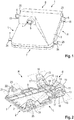
- Fig. 1 a perspective view of an electronic component, such as for example a sensor unit 1, to be attached by a bracket device 2 according to the invention on a windshield of a vehicle, in particular an automobile.
- an electronic component such as for example a sensor unit 1
- a bracket device 2 according to the invention on a windshield of a vehicle, in particular an automobile.
- the sensor unit 1 comprises a sensor housing 3 and a sensor means 4 arranged within the sensor housing 3.
- the sensor unit 1 is for example a camera comprising a camera housing, wherein a camera lens 5, as part of a sensor means, of the camera is arranged within an opening of the camera housing.
- the invention is neither restricted to a sensor unit or an electronic component nor to a camera as sensor unit 1 but can be applied to all kind of sensor units which are attachable by the bracket device to a windshield of a vehicle, particularly an automobile.
- the invention will be described based on a camera as an example of a sensor unit or electronic component.
- the term sensor unit is used but the term electronic component can be used instead.
- the sensor unit 1 and in particular the sensor housing 3 and further the inventive bracket device 2 in which the sensor unit 1 is received comprises a right side and a left side, a front side and a rear side or back side.
- the right side of the sensor housing 3 and the bracket device 2 is indicated with "R”
- the left side is indicated with “L”
- the front side is indicated with “F”
- the rear side or back side is indicated with “B” throughout the figures.
- the windshield is illustrated with a dashed line.
- first protrusions 6 are arranged opposite each other and close to or adjacent to the front side of the sensor unit 1 and its sensor housing 3.
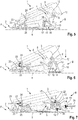
- each first protrusion 6 shown in the example in Figs. 1 and 5-7 is provided with an upper sensor unit contact portion 18 to contact a corresponding upper bracket contact portion 17 and a lower sensor unit contact portion 20 to contact a corresponding lower bracket contact portion 19.
- each second protrusion 7 shown in the example in Figs. 1 and 5-7 is provided with an upper front sensor unit contact portion 24 to contact a corresponding upper front bracket contact portion 22 and a lower front sensor unit contact portion 25 to contact a corresponding lower front bracket contact portion 23.
- the first and second protrusions 6, 7 of the sensor unit 1 and its sensor housing 3 can be identical or different as shown in the example in Fig. 1 .
- Fig. 2 a perspective view of an embodiment of the inventive bracket device is shown which is designed to receive and attach a sensor unit 1 as illustrated before exemplary in Fig. 1 on a windshield of a vehicle. Further, in Figs. 3 and 4 enlarged views of parts of the bracket device 2 according to Fig. 2 are shown. Figs. 5, 6 and 7 further, show a cross-sectional view of the bracket device 2 of Fig. 2 when mounting a sensor unit 1, such as a camera, as shown before in Fig. 1 , on the bracket device on a windshield 8.
- a sensor unit 1 such as a camera
- a multi-function camera is mounted on a windshield of a car using a bracket assembly.
- the bracket assembly must ensure a proper alignment of the camera in the car and needs to allow easy assembly and disassembly of the camera. Further, the bracket assembly has to prevent movement of the camera in the interface to avoid that an unintended camera movement can generate audible noise during operation.
- the bracket assembly was designed as a rigid part comprising reference surfaces corresponding to the camera reference system. Further, the bracket assembly was provided with elastic elements like snappers and metal leaf springs forming part of the bracket assembly. Other variants replaced the metal leaf springs with integrated plastic springs.
- metal springs such as leaf springs
- additional components results in increased costs and an increased complexity of the assembly. Further, development is more complicated and takes more time. Moreover, the manufacturing process needs to include an additional step of mounting the springs. Furthermore, the validation of the product is more difficult, since more tests are required and the risks of failing is increased.
- the inventive bracket device 2 provides a new, easy and error resistant mounting and dismounting concept for a sensor unit 1, such as the camera shown in the Figs. 1 and 5-7 .
- a relatively flexible bracket device 2 is provided, with a combination of auto guiding features and the body or base plate of the bracket device 2 with flexible fixing elements or flexible portions.
- no extra components are required and no fragile and precise snappers are needed.
- the bracket device 2 comprises a base plate 9, wherein the base plate 9 forms the bottom portion of the bracket device 2. Further, the bracket device 2 comprises a first spring portion 10, wherein the first spring portion 10 is provided at the rear end of the base plate 9.
- the first spring portion 10 comprises a rear bracket contact portion 11 which contacts a corresponding rear sensor unit contact portion 12, when the sensor unit 1 and its sensor housing 3 is mounted on the bracket device 2 and has reached its mounting position or end position as shown in Fig. 7 . Due to its elasticity and/or flexibility the first spring portion 10 is pushed with its rear bracket contact portion 11 against the rear sensor unit contact portion 12 so that a first preload force 26 is applied to the sensor unit 1 by the first spring portion 10 as indicated with the arrow in Fig. 7 to hold the sensor unit 1 in place and prevents that the sensor unit 1 can move unintentionally rearward.
- the first preload force 26 results in a corresponding opposite fourth preload force 29, which will be described further below.
- the bracket device 2 comprises two second spring portions 13.
- One second spring portion 13 is provided at the right side of the base plate 9.
- the other second spring portion 13 is provided on the opposite side or on the left side of the base plate 9.
- Both second spring portions 13 are arranged opposite each other on the right and left side of the base plate 9.
- bracket device 2 comprises a third spring portion 14.
- the third spring portion is provided on the base plate between the two second spring portions.
- both second spring portions 13 are provided on the base plate 9, e.g., next to or adjacent to the rear end or the first spring portion 10.
- Each of the second spring portions 13 comprise a recess 15 to receive the first protrusions 6 of the sensor housing 3 and further an optional lead-in portion 16.
- Each lead-in portion 16 is designed to facilitate insertion of the sensor housing 3 with its first protrusions 6 between the second spring portions 13. After the sensor housing 3 is inserted with its first protrusions 6 between the lead-in portions 16 of the second spring portions 13, the sensor housing 3 can be moved along the lead-in portions until the sensor housing 3 with its first protrusion 6 reaches the corresponding recess 15 of the second spring portion 13.
- Each first protrusion 6 of the sensor unit 1 is received in the corresponding recess 15 when the sensor unit 1 and its sensor housing 3 is mounted on the bracket device 2 and has reached its mounting position or end position as shown in Fig. 7 .
- the second spring portion 13 and its recess 15 apply a second preload force 26 on the first protrusions 6 downward or towards the bracket device 2.
- each second spring portion 13 comprises an upper bracket contact portion 17 to contact the corresponding upper sensor unit contact portion 18 of the first protrusion 6 of sensor housing 3.
- the third spring portion 14 comprises a lower bracket contact portion 19 which contacts a corresponding lower sensor unit contact portion 20, when sensor housing 3 is mounted on the bracket device 2 and has reached its mounting position or end position as shown in Fig. 7 .
- third spring portion 14 pushes the sensor housing 3 and its two first protrusions 6 upwards and against the upper bracket contact portion 17 of each recess 15 of the second spring portion 13.
- the lower bracket contact portion 19 contacts the lower sensor unit contact portion 20 and further the upper bracket contact portion 17 contacts the corresponding upper sensor unit contact portion 18 of the first protrusion 6 of the sensor housing 3.
- the third spring portion applies a third preload force 28 on the bottom surface of the sensor unit 1 and in opposite direction to the second preload force 27 of the second spring portion 13.
- a second preload force 27 is applied on the first protrusion 6 of the sensor housing 3 downwards while a third preload force 28 is applied on the first protrusion 6 upwards or away from the bracket device to hold the first protrusion 6 as shown in Fig. 7 .
- the sensor unit 1 and its sensor housing 3 are held in place so that it cannot move unintentionally upwards and downwards.
- the bracket device 2 comprises a receiving and centering section 21 to receive and center the second protrusions 7 of the sensor housing 3 of the sensor unit 1.
- Each receiving and centering section 21 comprises at least one or as shown in the embodiment, e.g., in Fig. 6 and 7 for example two upper and lower front bracket contact portions 22, 23 to contact the corresponding upper and lower front sensor unit contact portions 24, 25 of the second protrusions 7.
- the upper and lower front bracket contact portions 22, 23 are further inclined relative to each other in the example shown in Figs. 6 and 7 to form a hopper or funnel to receive and position or center the corresponding second protrusions 7 of the sensor unit 1 and its sensor housing 3.
- One of the receiving and centering sections 21 is provided at the right side of the base plate 9.
- the other receiving and centering section 21 is provided on the opposite side or the left side of the base plate 9. Both receiving and centering sections 21 are arranged opposite each other on the right side and left side of the base plate 9.
- the two receiving and centering sections 21 are provided on the base plate 9, e.g., next to or adjacent to the front end of the base plate 9.
- the first spring portion 6 at the rear end of the base plate 9 pushes the sensor housing 3 and its second protrusion 7 against the receiving and centering section 21 by applying the first preload force 26.
- the sensor unit 1 is clamped between the first spring portion 10 and the receiving and centering sections 21 in its mounting positon as shown in Fig. 7 . Therefore, sensor unit 1 and its sensor housing 3 is held in place and prevents that the sensor unit 1 can move unintentionally forward and rearward.
- the invention describes a new and innovative way to mount a sensor unit 1 such as for example a camera on a bracket device 2 made of plastic and using the elastic and/or flexible spring portions 10, 13, 14 as described with respect to Figs. 5 to 7 in the following:
- Fig. 5 the inventive bracket device 2 and sensor unit 1 is shown.
- the sensor unit 2 in the example as shown is for example a camera.
- a camera body, containing a lens assembly 5 is fitted with two pins, i.e. second protrusions 7, comprising e.g. circular or rounded portions 24, 25, in the front and two pins, i.e. first protrusions 6, comprising circular or rounded portions 18, 20, in the back and, located on each side of the camera as fixing features.
- Said pins or first and second protrusions 6, 7 are used, in particular solely used, to properly align the camera as shown before in Fig. 1 to the car.
- the operator will rotate the back side of the camera body, i.e. sensor housing 3, towards the bracket device 2 so that the other two or first protrusions 6 of the sensor housing 3, i.e. camera housing, from the back will push the two elastics back handles, i.e. the second spring portions 13, apart and in the final position.
- the two elastic back handles, i.e. second spring portions 13, of the bracket device 2 snap over the first protrusions 6 of the camera housing, i.e., sensor housing 3 to hold the camera in position as shown, e.g. in Fig. 6 .
- the camera or sensor unit 1 is mounted on the bracket device 2.
- the bracket back spring i.e. the first spring portion 10
- the front fixing pins i.e. the second protrusions 7, of the camera towards the driving direction of the car or front direction of the car against the front top bottom centering surfaces, i.e., the upper front sensor unit contact portions 24 of the receiving and centering sections 21.
- This preload force will block the sensor unit 1 front-back motion as well as the top-bottom motion in the front.
- the lower spring i.e., the third spring portion 14 will push the camera housing 3 and the back fixing pins, i.e.
- the bracket front and back side holding surfaces, i.e. receiving and centering sections 21, and the lower bracket contact portion, i.e. recess 15, will block the first and second protrusions 6, 7 of the camera housing 3 from moving sideways.
- bracket device 2 will tighten the assembled camera sensor in all directions, leaving no free degrees of freedom and assuring a preload force 26-29 in all directions that prevents the creation of audible noise during operation.
- the main advantage of this solution is that the sensor unit, such as a camera, is pressed in all direction, assuring a snug fit of the assembly and also eliminates the small elastic and imprecise elements from the bracket device, like snappers.
- this bracket device is only one part.
- bracket device Furthermore, the way of mounting and dismounting the sensor unit, such as a camera, on the bracket device is simple and very intuitive.
Landscapes
- Engineering & Computer Science (AREA)
- Mechanical Engineering (AREA)
- Fittings On The Vehicle Exterior For Carrying Loads, And Devices For Holding Or Mounting Articles (AREA)
Abstract
Description
- The present invention relates to a bracket device for attaching at least one sensor unit, in particular a camera, on a windshield of a vehicle, in particular an automobile. Further the present invention relates to a system comprising said bracket device and a sensor unit and furthermore to a vehicle comprising such a system.
- In the automotive and other industries sensors or electrical/ electronic components are mounted on the windshield using custom designed brackets.
- In
US 2012/0207461 A1 an in-vehicle camera is provided which has a case and a lens and which is attached in a vehicle interior so that the lens is exposed at a top face of the case and the top face is opposed to a windshield. The in-vehicle camera is attached to the windshield of the vehicle by a bracket. The bracket includes a top board, latches a rear board and two plate springs. - However, such plate springs are difficult to mount and have to be manufacture in a separate manufacturing process.
- Against this background, an objective of the present invention is to provide an improved bracket device comprising at least one sensor unit, for a windshield of a vehicle, an improved system comprising said bracket device and further an improved vehicle comprising said system.
- This objective is achieved according to the invention by a bracket device having the features of
claim 1 and a system having the features ofclaim 9 and further a vehicle having the features ofclaim 14. - Bracket device for attaching at least one electronic component on a windshield of a vehicle, wherein the attachment system comprises:
- two receiving and centering sections for receiving and centering the sensor unit, wherein the two receiving and centering sections are provided at opposite sides of the bracket device and adjacent a front end of the bracket device, and at least a first spring portion provided at a rear end of the bracket device, wherein the first spring portion is designed to apply a first preload force on the sensor unit to push the sensor unit into and against the receiving and centering sections.
- The above mentioned bracket device provides a device which allows fixation of a sensor unit as electronic component so that the electronic component cannot be moved unintentionally forward or backward along the bracket device which would otherwise impair the function of the electronic component, such as for example a camera, and could further result in unintended noise or loosening of the electronic component.
- The concept underlying the invention is to provide a new bracket device concept which allows attaching an electronic component on a bracket device without requiring additional components such as metal leaf springs and which hold the electronic component in place without the generation of noise due to an unintended movement of the electronic component relative to the camera
- Advantageous embodiments and developments of the invention emerge from the additional subordinate claims and from the description with reference to the drawing figures.
- According to an embodiment of the invention each receiving and centering section comprises at least an upper or lower front bracket contact portion which is in contact with a corresponding upper and lower front sensor unit contact portion of the sensor unit, when the sensor unit is in its mounting portion on the bracket device. Thus, the sensor unit can securely held in place.
- In another embodiment of the invention the first spring portion comprises a rear bracket contact portion which is in contact with a rear sensor unit contact portion to apply the first preload force on the electronic component, when the sensor unit is in its mounting portion on the bracket device. The first spring portion can partially enclose the rear end of the sensor unit and can hold the sensor unit securely in place due to the application of the first preload force.
- In a further embodiment of the invention the bracket device comprises two second spring portions, provided at the opposite sides or right and left side of the bracket device and adjacent the first spring portion. Each second spring portion is designed to apply a second preload force on the electronic component to push the electronic component downward or toward the bracket device. Due to the second preload force the sensor unit cannot move unintentionally upwards and downwards or toward and away from the bracket device and its base plate.
- According to an embodiment of the invention each second spring portion comprises a recess to receive a portion of the sensor unit. The recess comprises an upper bracket contact portion which is in contact with a corresponding upper sensor unit contact portion, when the sensor unit is in its mounting portion on the bracket device. This also results in that the sensor unit can be held securely in place. In particular the recess prevents that the sensor unit can be moved out of the bracket device, since the portion of the sensor unit, i.e. the first protrusion is enclosed by the walls of the recess.
- In another embodiment of the invention the bracket device comprises a third spring portion which is provided between the two second spring portions. The third spring portion is designed to apply a third preload force on the sensor unit away from the bracket device and against the recess of the second spring portion. Thus the second and third preload forces are applied in opposite directions of the sensor unit and particular its first protrusions so that the sensor unit is securely held in place.
- In a further embodiment of the invention the third spring portion comprises a lower bracket contact portion which is in contact with a lower sensor unit contact portion of the sensor unit, when the sensor unit is in its mounting portion on the bracket device. The sensor unit is therefore securely held within the recess of the second spring portion since the sensor unit is in contact with the upper sensor unit contact portion of the second spring portion when the third preload force is applied by the third spring portion.
- According to an embodiment of the invention each second spring portion comprises at its outer end a lead-in portion. Such a lead-in portion facilitates insertion of the first protrusions of the sensor unit between the second spring portions and movement of the first protrusions into the recesses of the second spring portion.
- In another embodiment of the invention, the sensor unit comprises a sensor housing, wherein the sensor housing comprises on its opposite sides a front protrusion, wherein each front protrusion is received and centered in the corresponding receiving and centering section, wherein each front protrusion comprises the upper and lower front sensor unit contact portion which is in contact with the upper and lower front bracket contact portion of the corresponding receiving and centering section.
- In a further embodiment of the invention the sensor housing comprises further on its opposite sides a further or rear protrusion, wherein each further or rear protrusion is received in the recess of the corresponding second spring portion, wherein each further or rear protrusion comprises the upper sensor unit contact portion and the lower sensor unit contact portion.
- According to an embodiment of the invention the upper sensor unit contact portion of the protrusion is in contact with the upper bracket contact portion of the recess of the second spring portion and the lower sensor unit contact portion of the sensor unit is on contact with the lower bracket contact portion of the third spring portion, when the sensor unit is in its mounting portion on the bracket device.
- In an embodiment of the invention the sensor unit is for example a camera. However, the sensor unit can be any other electronic component suitable to be attached to a windshield by the bracket device.
- In another embodiment of the invention a vehicle, in particular an automobile, comprises such a system comprising the bracket device and a sensor unit.
- The present invention is explained below in greater detail with the aid of embodiments specified in the schematic figures in the drawings. These are as follows:
- Fig. 1
- shows a perspective view of an example of a sensor unit such as a camera;
- Fig. 2
- shows a perspective view of an inventive bracket device for mounting a sensor unit as shown in
Fig. 1 on a windshield of a vehicle; - Fig. 3
- shows an enlarged view of a part of the bracket device according to
Fig. 3 ; - Fig. 4
- shows another enlarged view of a part of the bracket device according to
Fig. 3 ; - Fig. 5
- shows a cross-sectional view of the bracket device according to
Figs. 2-4 and the sensor unit according toFig. 1 ; - Fig. 6
- shows another a cross-sectional view of the bracket device according to
Figs. 2-4 and the sensor unit according toFig. 1 ; and - Fig. 7
- shows a cross-sectional view of the bracket device according to
Figs. 2-4 and the sensor unit according toFig. 1 , wherein the sensor unit is in its mounting position on the bracket device. - The accompanying drawings should convey further understanding of the embodiments of the invention. They illustrate embodiments of the invention and clarify the principles and concepts behind the invention in conjunction with the description. Other embodiments and many of the described advantages are apparent with respect to the drawings. The elements of the drawings are not necessarily illustrated true to scale in relation to each other.
- In the figures in the drawing, the same elements, features and components, or those serving the same function and having the same effect, are provided with the same reference numerals in each case - unless otherwise specified.
- In
Fig. 1 a perspective view of an electronic component, such as for example asensor unit 1, to be attached by abracket device 2 according to the invention on a windshield of a vehicle, in particular an automobile. - The
sensor unit 1 comprises asensor housing 3 and a sensor means 4 arranged within thesensor housing 3. In the example shown inFig. 1 thesensor unit 1 is for example a camera comprising a camera housing, wherein acamera lens 5, as part of a sensor means, of the camera is arranged within an opening of the camera housing. However, the invention is neither restricted to a sensor unit or an electronic component nor to a camera assensor unit 1 but can be applied to all kind of sensor units which are attachable by the bracket device to a windshield of a vehicle, particularly an automobile. In the following the invention will be described based on a camera as an example of a sensor unit or electronic component. In the following the term sensor unit is used but the term electronic component can be used instead. - As shown in
Fig. 1 and followingFigs. 2 to 7 thesensor unit 1 and in particular thesensor housing 3 and further theinventive bracket device 2 in which thesensor unit 1 is received comprises a right side and a left side, a front side and a rear side or back side. The right side of thesensor housing 3 and thebracket device 2 is indicated with "R", the left side is indicated with "L", the front side is indicated with "F" and the rear side or back side is indicated with "B" throughout the figures. Further, in followingFigs. 5 to 7 , the windshield is illustrated with a dashed line. - The right side and the left side of the
sensor unit 1 and itssensor housing 3 are each provided which afirst protrusion 6 and asecond protrusion 7. In the example shown inFig. 1 , thefirst protrusions 6 are arranged opposite each other and close to or adjacent to the front side of thesensor unit 1 and itssensor housing 3. Further, eachfirst protrusion 6 shown in the example inFigs. 1 and5-7 is provided with an upper sensorunit contact portion 18 to contact a corresponding upperbracket contact portion 17 and a lower sensorunit contact portion 20 to contact a corresponding lowerbracket contact portion 19. - The
second protrusions 7 are also arranged opposite each other and close to or adjacent to the rear side of thesensor unit 1 and itssensor housing 3. Further, eachsecond protrusion 7 shown in the example inFigs. 1 and5-7 is provided with an upper front sensorunit contact portion 24 to contact a corresponding upper frontbracket contact portion 22 and a lower front sensorunit contact portion 25 to contact a corresponding lower frontbracket contact portion 23. - The first and
second protrusions sensor unit 1 and itssensor housing 3 can be identical or different as shown in the example inFig. 1 . - In
Fig. 2 a perspective view of an embodiment of the inventive bracket device is shown which is designed to receive and attach asensor unit 1 as illustrated before exemplary inFig. 1 on a windshield of a vehicle. Further, inFigs. 3 and 4 enlarged views of parts of thebracket device 2 according toFig. 2 are shown.Figs. 5, 6 and 7 further, show a cross-sectional view of thebracket device 2 ofFig. 2 when mounting asensor unit 1, such as a camera, as shown before inFig. 1 , on the bracket device on awindshield 8. - Currently, a multi-function camera (MFC) is mounted on a windshield of a car using a bracket assembly. The bracket assembly must ensure a proper alignment of the camera in the car and needs to allow easy assembly and disassembly of the camera. Further, the bracket assembly has to prevent movement of the camera in the interface to avoid that an unintended camera movement can generate audible noise during operation. To fulfil these requirements the bracket assembly was designed as a rigid part comprising reference surfaces corresponding to the camera reference system. Further, the bracket assembly was provided with elastic elements like snappers and metal leaf springs forming part of the bracket assembly. Other variants replaced the metal leaf springs with integrated plastic springs.
- However, the use of metal springs such as leaf springs as additional components results in increased costs and an increased complexity of the assembly. Further, development is more complicated and takes more time. Moreover, the manufacturing process needs to include an additional step of mounting the springs. Furthermore, the validation of the product is more difficult, since more tests are required and the risks of failing is increased.
- On the other hand, using plastic springs on a rigid bracket requires a longer developing time, since more time is required for simulation to achieve the right shape and the required elasticity. By incorporating these springs on the bracket, the assembly complexity can be reduced on the one hand. However, on the other hand the complexity of the tool is increased and further the risks during validation are increased.
- The invention therefore seeks to provide an
improved bracket device 2 for mounting asensor unit 1 on awindshield 8 of vehicle, in particular an automobile. - As will be described in the following with respect to
Figs. 5 to 7 , theinventive bracket device 2 provides a new, easy and error resistant mounting and dismounting concept for asensor unit 1, such as the camera shown in theFigs. 1 and5-7 . According to the invention a relativelyflexible bracket device 2 is provided, with a combination of auto guiding features and the body or base plate of thebracket device 2 with flexible fixing elements or flexible portions. According to theinventive bracket device 2, no extra components are required and no fragile and precise snappers are needed. - As shown in
Figs. 2 to 4 , thebracket device 2 comprises abase plate 9, wherein thebase plate 9 forms the bottom portion of thebracket device 2. Further, thebracket device 2 comprises afirst spring portion 10, wherein thefirst spring portion 10 is provided at the rear end of thebase plate 9. Thefirst spring portion 10 comprises a rearbracket contact portion 11 which contacts a corresponding rear sensorunit contact portion 12, when thesensor unit 1 and itssensor housing 3 is mounted on thebracket device 2 and has reached its mounting position or end position as shown inFig. 7 . Due to its elasticity and/or flexibility thefirst spring portion 10 is pushed with its rearbracket contact portion 11 against the rear sensorunit contact portion 12 so that afirst preload force 26 is applied to thesensor unit 1 by thefirst spring portion 10 as indicated with the arrow inFig. 7 to hold thesensor unit 1 in place and prevents that thesensor unit 1 can move unintentionally rearward. Thefirst preload force 26 results in a corresponding oppositefourth preload force 29, which will be described further below. - Further, the
bracket device 2 comprises twosecond spring portions 13. Onesecond spring portion 13 is provided at the right side of thebase plate 9. The othersecond spring portion 13 is provided on the opposite side or on the left side of thebase plate 9. Bothsecond spring portions 13 are arranged opposite each other on the right and left side of thebase plate 9. - Further, the
bracket device 2 comprises athird spring portion 14. The third spring portion is provided on the base plate between the two second spring portions. - As shown in the example in
Fig. 2 bothsecond spring portions 13 are provided on thebase plate 9, e.g., next to or adjacent to the rear end or thefirst spring portion 10. - Each of the
second spring portions 13 comprise arecess 15 to receive thefirst protrusions 6 of thesensor housing 3 and further an optional lead-inportion 16. Each lead-inportion 16 is designed to facilitate insertion of thesensor housing 3 with itsfirst protrusions 6 between thesecond spring portions 13. After thesensor housing 3 is inserted with itsfirst protrusions 6 between the lead-inportions 16 of thesecond spring portions 13, thesensor housing 3 can be moved along the lead-in portions until thesensor housing 3 with itsfirst protrusion 6 reaches thecorresponding recess 15 of thesecond spring portion 13. Eachfirst protrusion 6 of thesensor unit 1 is received in thecorresponding recess 15 when thesensor unit 1 and itssensor housing 3 is mounted on thebracket device 2 and has reached its mounting position or end position as shown inFig. 7 . Thesecond spring portion 13 and itsrecess 15 apply asecond preload force 26 on thefirst protrusions 6 downward or towards thebracket device 2. - The
recess 15 of eachsecond spring portion 13 comprises an upperbracket contact portion 17 to contact the corresponding upper sensorunit contact portion 18 of thefirst protrusion 6 ofsensor housing 3. - Further, the
third spring portion 14 comprises a lowerbracket contact portion 19 which contacts a corresponding lower sensorunit contact portion 20, whensensor housing 3 is mounted on thebracket device 2 and has reached its mounting position or end position as shown inFig. 7 . - Due to the elasticity and/or flexibility of
third spring portion 14, thethird spring portion 14 pushes thesensor housing 3 and its twofirst protrusions 6 upwards and against the upperbracket contact portion 17 of eachrecess 15 of thesecond spring portion 13. Thus, when thesensor housing 3 is mounted on thebracket device 2 and has reached its mounting position or end position as shown inFig. 7 , the lowerbracket contact portion 19 contacts the lower sensorunit contact portion 20 and further the upperbracket contact portion 17 contacts the corresponding upper sensorunit contact portion 18 of thefirst protrusion 6 of thesensor housing 3. The third spring portion applies athird preload force 28 on the bottom surface of thesensor unit 1 and in opposite direction to thesecond preload force 27 of thesecond spring portion 13. - Therefore a
second preload force 27 is applied on thefirst protrusion 6 of thesensor housing 3 downwards while athird preload force 28 is applied on thefirst protrusion 6 upwards or away from the bracket device to hold thefirst protrusion 6 as shown inFig. 7 . Thus, thesensor unit 1 and itssensor housing 3 are held in place so that it cannot move unintentionally upwards and downwards. - Moreover, the
bracket device 2 comprises a receiving and centeringsection 21 to receive and center thesecond protrusions 7 of thesensor housing 3 of thesensor unit 1. Each receiving and centeringsection 21 comprises at least one or as shown in the embodiment, e.g., inFig. 6 and 7 for example two upper and lower frontbracket contact portions unit contact portions second protrusions 7. The upper and lower frontbracket contact portions Figs. 6 and 7 to form a hopper or funnel to receive and position or center the correspondingsecond protrusions 7 of thesensor unit 1 and itssensor housing 3. - One of the receiving and centering
sections 21 is provided at the right side of thebase plate 9. The other receiving and centeringsection 21 is provided on the opposite side or the left side of thebase plate 9. Both receiving and centeringsections 21 are arranged opposite each other on the right side and left side of thebase plate 9. - Further in the embodiment shown in
Figs. 2 ,3 and5 to 7 , the two receiving and centeringsections 21 are provided on thebase plate 9, e.g., next to or adjacent to the front end of thebase plate 9. - When the
sensor housing 3 is mounted on thebracket device 2 and has reached its mounting position or end position as shown inFig. 7 , thefirst spring portion 6 at the rear end of thebase plate 9 pushes thesensor housing 3 and itssecond protrusion 7 against the receiving and centeringsection 21 by applying thefirst preload force 26. This results in an oppositefourth preload force 28 applied by the receiving and centeringsections 21 on the front end of thesensor unit 1. Thus thesensor unit 1 is clamped between thefirst spring portion 10 and the receiving and centeringsections 21 in its mounting positon as shown inFig. 7 . Therefore,sensor unit 1 and itssensor housing 3 is held in place and prevents that thesensor unit 1 can move unintentionally forward and rearward. - The invention describes a new and innovative way to mount a
sensor unit 1 such as for example a camera on abracket device 2 made of plastic and using the elastic and/orflexible spring portions Figs. 5 to 7 in the following: - In
Fig. 5 theinventive bracket device 2 andsensor unit 1 is shown. Thesensor unit 2 in the example as shown is for example a camera. A camera body, containing alens assembly 5 is fitted with two pins, i.e.second protrusions 7, comprising e.g. circular orrounded portions first protrusions 6, comprising circular orrounded portions second protrusions Fig. 1 to the car. - The
bracket device 2 is designed in such a way that from the back of thebase plate 9 the back spring, i.e.first spring portion 13, is extended around the camera. - Besides the bracket field of view another
elastic spring 14, i.e. third spring portion, is installed on thebase plate 9 as shown before inFig. 4 . - As shown, e.g., in
Fig. 3 , the front fixing features comprises two receiving and centeringsections 21 each comprising for example a front top-bottom centering surfaces, i.e. upper frontbracket contact portions 22, and a front side holding surfaces, i.e., other lower frontbracket contact portion 23. Further, as shown inFig. 4 , the back fixing features comprises thesecond spring portions 13, each comprising arecess 15 with a back top holding surface, i.e. upperbracket contact portion 17, and athird spring portions 14 which comprises back side holding surfaces, i.e., a lowerbracket contact portion 19. As described before thesecond spring portions 13 can each comprise an assembly lead in surfaces, i.e., a lead-inportions 16, and can further serves as a quick and easy camera disassembly or release features. - To assemble the camera as an example of a
sensor unit 1 to thebracket device 2, it needs to be brought in contact with the front of thebracket device 2 first until the both second orfront protrusions 7 of the camera, i.e.sensor unit 1, are touching both surfaces of the front top-bottom centering surfaces, i.e. the upper and lower frontbracket contact portions sections 21 shown, e.g., inFig. 5 . This aligns the camera to thebracket device 2 in the front and only allows a rotation around the axis of the front orsecond protrusion 7. - After that, the operator will rotate the back side of the camera body, i.e.
sensor housing 3, towards thebracket device 2 so that the other two orfirst protrusions 6 of thesensor housing 3, i.e. camera housing, from the back will push the two elastics back handles, i.e. thesecond spring portions 13, apart and in the final position. The two elastic back handles, i.e.second spring portions 13, of thebracket device 2 snap over thefirst protrusions 6 of the camera housing, i.e.,sensor housing 3 to hold the camera in position as shown, e.g. inFig. 6 . - As mentioned before, in
Fig. 7 the camera orsensor unit 1 is mounted on thebracket device 2. In this state the bracket back spring, i.e. thefirst spring portion 10, will push the camera body and the front fixing pins, i.e. thesecond protrusions 7, of the camera towards the driving direction of the car or front direction of the car against the front top bottom centering surfaces, i.e., the upper front sensorunit contact portions 24 of the receiving and centeringsections 21. This preload force will block thesensor unit 1 front-back motion as well as the top-bottom motion in the front. In the back, the lower spring, i.e., thethird spring portion 14, will push thecamera housing 3 and the back fixing pins, i.e. thefirst protrusions 6, of the camera against the upper holding surfaces, i.e. upperbracket contact portions 17 of eachrecess 15 of thesecond spring portions 13. This preload force will block the top-bottom motion of the camera in the back. For the side direction, i.e. left-right direction, the bracket front and back side holding surfaces, i.e. receiving and centeringsections 21, and the lower bracket contact portion, i.e.recess 15, will block the first andsecond protrusions camera housing 3 from moving sideways. - This way, the
bracket device 2 will tighten the assembled camera sensor in all directions, leaving no free degrees of freedom and assuring a preload force 26-29 in all directions that prevents the creation of audible noise during operation. - The main advantage of this solution is that the sensor unit, such as a camera, is pressed in all direction, assuring a snug fit of the assembly and also eliminates the small elastic and imprecise elements from the bracket device, like snappers.
- Further, no other elements needs to be preassembled or manufactured, like leaf metal springs or wire springs, this bracket device is only one part.
- Furthermore, the way of mounting and dismounting the sensor unit, such as a camera, on the bracket device is simple and very intuitive.
- Although the present invention has been fully described above by means of preferred embodiments, it is not limited to the above, but may be modified in a number of ways.
-
- 1
- sensor unit
- 2
- bracket device
- 3
- sensor housing
- 4
- sensor means
- 5
- camera lens
- 6
- first protrusion
- 7
- second protrusion
- 8
- windshield
- 9
- baseplate
- 10
- first spring portion
- 11
- rear bracket contact portion
- 12
- rear sensor unit contact portion
- 13
- second spring portion
- 14
- third spring portion
- 15
- recess
- 16
- lead-in portion
- 17
- upper bracket contact portion (of recess of second spring portion)
- 18
- upper sensor unit contact portion (of second protrusion)
- 19
- lower bracket contact portion (of third spring portion)
- 20
- lower sensor unit contact portion (of sensor unit or second protrusion)
- 21
- receiving and centering section
- 22
- upper front bracket contact portion (of receiving and centering section)
- 23
- lower front bracket contact portion (receiving and centering section)
- 24
- upper front sensor unit contact portion
- 25
- lower front sensor unit contact portion
- 26
- first preload force
- 27
- second preload force
- 28
- third preload force
- 29
- fourth preload force
Claims (14)
- Bracket device (2) for attaching at least sensor unit (1) on a windshield (8) of a vehicle, wherein the bracket device (2) comprises:two receiving and centering sections (21) for receiving and centering the sensor unit (1), wherein the two receiving and centering sections (21) are provided at opposite sides of the bracket device (2) and adjacent a front end of the bracket device (2), andat least a first spring portion (10) provided at a rear end of the bracket device (2), wherein the first spring portion (10) is designed to apply a first preload force (26) on the sensor unit (1) to push the sensor unit (1) into and against the receiving and centering sections (21).
- Bracket device according to claim 1, wherein each receiving and centering section (21) comprises at least an upper or lower front bracket contact portion (22, 23) which is in contact with a corresponding upper and lower front sensor unit contact portion (24, 25) of the sensor unit (1), when the sensor unit (1) is in its mounting portion on the bracket device (2).
- Bracket device according to claim 1 or 2, wherein the first spring portion (10) comprises a rear bracket contact portion (11) which is in contact with a rear sensor unit contact portion (12) to apply the first preload force (26) on the sensor unit (1), when the sensor unit (1) is in its mounting portion on the bracket device (2).
- Bracket device according to any of the preceding claims, wherein the bracket device (2) comprises two second spring portions (13), provided at the opposite sides of the bracket device (2) and adjacent the first spring portion (10), wherein each second spring portion (13) is designed to apply a second preload force (27) on the sensor unit (1) to push the sensor unit (1) downward or toward the bracket device (2).
- Bracket device according to claim 4, wherein each second spring portion (13) comprises a recess (15) to receive a portion (6) of the sensor unit (1), wherein the recess (15) comprises an upper bracket contact portion (17) which is in contact with a corresponding upper sensor unit contact portion (18), when the sensor unit (1) is in its mounting portion on the bracket device (2).
- Bracket device according to claim 4 or 5, wherein the bracket device (2) comprises a third spring portion (14) which is provided between the two second spring portions (13), wherein the third spring portion (14) is designed to apply a third preload force (28) on the sensor unit (1) away from the bracket device (2) and against the recess (15) of the second spring portion (13).
- Bracket device according to claim 6, wherein the third spring portion (14) comprises a lower bracket contact portion (19) which is in contact with a lower sensor unit contact portion (20) of the sensor unit (1), when the sensor unit (1) is in its mounting portion on the bracket device (2).
- Bracket device according to any one of claims 4 to 7, wherein each second spring portion (13) comprises at its outer and a lead-in portion (16).
- System comprising a bracket device according to any one of the preceding claims and a sensor unit (1) mounted on the bracket device (2).
- System according to claim 9, wherein the sensor unit (1) comprises on its opposite sides a protrusion (7), wherein each protrusion (7) is received and centered in the corresponding receiving and centering section (21), wherein each protrusion (7) comprises the upper and lower front sensor unit contact portion (24, 25) which is in contact with the upper and lower front bracket contact portion (22, 23) of the corresponding receiving and centering section (21).
- System according to claim 9 or 10, wherein the sensor unit (1) comprises further on its opposite sides a further protrusion (6), wherein each further protrusion (6) is received in the recess (15) of the corresponding second spring portion (13), wherein each further protrusion (6) comprises the upper sensor unit contact portion (18) and the lower sensor unit contact portion (20).
- System according to claim 9, 10 or 11, wherein the upper sensor unit contact portion (18) of the protrusion (6) is in contact with the upper bracket contact portion (17) of the recess (15) of the second spring portion (13) and the lower sensor unit contact portion (20) of the sensor unit (1) is in contact with the lower bracket contact portion (19) of the third spring portion (14), when the sensor unit (1) is in its mounting portion on the bracket device (2).
- System according to claim 9, 10, 11 or 12, wherein the sensor unit (1) is a camera.
- A vehicle comprising a system according to any of claims 9 to 13.
Priority Applications (1)
| Application Number | Priority Date | Filing Date | Title |
|---|---|---|---|
| EP16465558.1A EP3330131B1 (en) | 2016-12-05 | 2016-12-05 | Bracket device, system comprising a bracket device and a sensor unit, and a vehicle |
Applications Claiming Priority (1)
| Application Number | Priority Date | Filing Date | Title |
|---|---|---|---|
| EP16465558.1A EP3330131B1 (en) | 2016-12-05 | 2016-12-05 | Bracket device, system comprising a bracket device and a sensor unit, and a vehicle |
Publications (2)
| Publication Number | Publication Date |
|---|---|
| EP3330131A1 true EP3330131A1 (en) | 2018-06-06 |
| EP3330131B1 EP3330131B1 (en) | 2019-11-13 |
Family
ID=57681517
Family Applications (1)
| Application Number | Title | Priority Date | Filing Date |
|---|---|---|---|
| EP16465558.1A Active EP3330131B1 (en) | 2016-12-05 | 2016-12-05 | Bracket device, system comprising a bracket device and a sensor unit, and a vehicle |
Country Status (1)
| Country | Link |
|---|---|
| EP (1) | EP3330131B1 (en) |
Cited By (7)
| Publication number | Priority date | Publication date | Assignee | Title |
|---|---|---|---|---|
| WO2019110518A1 (en) * | 2017-12-07 | 2019-06-13 | Continental Automotive Gmbh | Housing receptacle for a motor-vehicle radar sensor |
| WO2020140016A1 (en) | 2018-12-28 | 2020-07-02 | Zf Active Safety And Electronics Us Llc | Driver assist system |
| US10710514B2 (en) * | 2004-12-15 | 2020-07-14 | Magna Electronics Inc. | Accessory mounting system for a vehicle |
| EP3835134A1 (en) * | 2019-12-09 | 2021-06-16 | Veoneer Sweden AB | Attachment arrangement for a camera module at a vehicle |
| CN113316530A (en) * | 2019-02-08 | 2021-08-27 | 株式会社利富高 | Bracket for vehicle-mounted camera device |
| WO2022069206A1 (en) * | 2020-09-30 | 2022-04-07 | Zf Friedrichshafen Ag | Mounting arrangement for a driver assist system |
| FR3115006A1 (en) * | 2020-10-08 | 2022-04-15 | Renault | Mounting bracket for an optical sensor on a glazed surface of a vehicle. |
Citations (4)
| Publication number | Priority date | Publication date | Assignee | Title |
|---|---|---|---|---|
| US20120207461A1 (en) | 2011-02-10 | 2012-08-16 | Denso Corporation | In-vehicle camera |
| WO2013123161A1 (en) * | 2012-02-17 | 2013-08-22 | Magna Electronics, Inc. | Vehicle vision system with light baffling system |
| US20140016919A1 (en) * | 2010-12-21 | 2014-01-16 | Denso Corporation | In-Vehicle Camera Unit Having Camera Built Into Body |
| DE102016203406A1 (en) * | 2015-03-05 | 2016-09-08 | Toyota Jidosha Kabushiki Kaisha | VEHICLE BOARD CAMERA ATTACHMENT STRUCTURE |
-
2016
- 2016-12-05 EP EP16465558.1A patent/EP3330131B1/en active Active
Patent Citations (4)
| Publication number | Priority date | Publication date | Assignee | Title |
|---|---|---|---|---|
| US20140016919A1 (en) * | 2010-12-21 | 2014-01-16 | Denso Corporation | In-Vehicle Camera Unit Having Camera Built Into Body |
| US20120207461A1 (en) | 2011-02-10 | 2012-08-16 | Denso Corporation | In-vehicle camera |
| WO2013123161A1 (en) * | 2012-02-17 | 2013-08-22 | Magna Electronics, Inc. | Vehicle vision system with light baffling system |
| DE102016203406A1 (en) * | 2015-03-05 | 2016-09-08 | Toyota Jidosha Kabushiki Kaisha | VEHICLE BOARD CAMERA ATTACHMENT STRUCTURE |
Cited By (11)
| Publication number | Priority date | Publication date | Assignee | Title |
|---|---|---|---|---|
| US10710514B2 (en) * | 2004-12-15 | 2020-07-14 | Magna Electronics Inc. | Accessory mounting system for a vehicle |
| WO2019110518A1 (en) * | 2017-12-07 | 2019-06-13 | Continental Automotive Gmbh | Housing receptacle for a motor-vehicle radar sensor |
| WO2020140016A1 (en) | 2018-12-28 | 2020-07-02 | Zf Active Safety And Electronics Us Llc | Driver assist system |
| CN113260534A (en) * | 2018-12-28 | 2021-08-13 | Zf主动安全和电子美国有限公司 | Driver assistance system |
| EP3902706A4 (en) * | 2018-12-28 | 2022-11-09 | ZF Active Safety and Electronics US LLC | Driver assist system |
| EP4275962A3 (en) * | 2018-12-28 | 2023-12-06 | ZF Active Safety and Electronics US LLC | Driver assist system |
| CN113260534B (en) * | 2018-12-28 | 2024-08-09 | Zf主动安全和电子美国有限公司 | Driver assistance system |
| CN113316530A (en) * | 2019-02-08 | 2021-08-27 | 株式会社利富高 | Bracket for vehicle-mounted camera device |
| EP3835134A1 (en) * | 2019-12-09 | 2021-06-16 | Veoneer Sweden AB | Attachment arrangement for a camera module at a vehicle |
| WO2022069206A1 (en) * | 2020-09-30 | 2022-04-07 | Zf Friedrichshafen Ag | Mounting arrangement for a driver assist system |
| FR3115006A1 (en) * | 2020-10-08 | 2022-04-15 | Renault | Mounting bracket for an optical sensor on a glazed surface of a vehicle. |
Also Published As
| Publication number | Publication date |
|---|---|
| EP3330131B1 (en) | 2019-11-13 |
Similar Documents
| Publication | Publication Date | Title |
|---|---|---|
| EP3330131B1 (en) | Bracket device, system comprising a bracket device and a sensor unit, and a vehicle | |
| US10252684B2 (en) | Attachment structure for in-vehicle camera | |
| US8791611B2 (en) | Device for the contact and attachment of an electric component in a motor vehicle | |
| US9027960B1 (en) | Front airbag device | |
| KR101789847B1 (en) | Modular actuator for vehicle transmission | |
| JPWO2018092473A1 (en) | Automotive electronic equipment mounting structure | |
| KR101081763B1 (en) | Windshield wiper, especially for a motor vehicle | |
| JP2011133003A (en) | Pipe holder | |
| JP2020524777A (en) | A holder for fixing a sensor, particularly a radar sensor to a vehicle, and a system including the holder and the sensor | |
| EP2000364A8 (en) | A dashboard assembly for a motor vehicle provided with a connector for connecting a portable electronic device | |
| US8143543B2 (en) | Actuating element | |
| JP6431781B2 (en) | Vehicle lighting | |
| CN103456535A (en) | Press operation device | |
| JP6732671B2 (en) | Panel device and method of assembling panel device | |
| JP2014503411A (en) | Window glass wiper device for automobiles | |
| JP2009099364A (en) | Vehicular antenna connection device | |
| JP4869252B2 (en) | Vehicle module and improved bodywork element including improved centering means for vehicle bodywork | |
| US11536417B2 (en) | Bracket and holding structure of electrical junction box | |
| JPWO2018233779A5 (en) | ||
| JP6341817B2 (en) | Inner mirror structure for vehicles | |
| KR20190088976A (en) | A steering wheel, an operating unit for such a steering wheel, and a steering wheel module and a method of manufacturing the same | |
| JP7294871B2 (en) | Connectors and electrical connectors | |
| WO2008062573A1 (en) | Tube clamp | |
| JP2018008604A (en) | On-vehicle component with fixing clamp part | |
| JP4361315B2 (en) | In-vehicle device mounting structure and in-vehicle device |
Legal Events
| Date | Code | Title | Description |
|---|---|---|---|
| PUAI | Public reference made under article 153(3) epc to a published international application that has entered the european phase |
Free format text: ORIGINAL CODE: 0009012 |
|
| STAA | Information on the status of an ep patent application or granted ep patent |
Free format text: STATUS: THE APPLICATION HAS BEEN PUBLISHED |
|
| AK | Designated contracting states |
Kind code of ref document: A1 Designated state(s): AL AT BE BG CH CY CZ DE DK EE ES FI FR GB GR HR HU IE IS IT LI LT LU LV MC MK MT NL NO PL PT RO RS SE SI SK SM TR |
|
| AX | Request for extension of the european patent |
Extension state: BA ME |
|
| STAA | Information on the status of an ep patent application or granted ep patent |
Free format text: STATUS: REQUEST FOR EXAMINATION WAS MADE |
|
| 17P | Request for examination filed |
Effective date: 20181206 |
|
| RBV | Designated contracting states (corrected) |
Designated state(s): AL AT BE BG CH CY CZ DE DK EE ES FI FR GB GR HR HU IE IS IT LI LT LU LV MC MK MT NL NO PL PT RO RS SE SI SK SM TR |
|
| STAA | Information on the status of an ep patent application or granted ep patent |
Free format text: STATUS: EXAMINATION IS IN PROGRESS |
|
| 17Q | First examination report despatched |
Effective date: 20190207 |
|
| GRAP | Despatch of communication of intention to grant a patent |
Free format text: ORIGINAL CODE: EPIDOSNIGR1 |
|
| STAA | Information on the status of an ep patent application or granted ep patent |
Free format text: STATUS: GRANT OF PATENT IS INTENDED |
|
| INTG | Intention to grant announced |
Effective date: 20190710 |
|
| GRAS | Grant fee paid |
Free format text: ORIGINAL CODE: EPIDOSNIGR3 |
|
| GRAA | (expected) grant |
Free format text: ORIGINAL CODE: 0009210 |
|
| STAA | Information on the status of an ep patent application or granted ep patent |
Free format text: STATUS: THE PATENT HAS BEEN GRANTED |
|
| AK | Designated contracting states |
Kind code of ref document: B1 Designated state(s): AL AT BE BG CH CY CZ DE DK EE ES FI FR GB GR HR HU IE IS IT LI LT LU LV MC MK MT NL NO PL PT RO RS SE SI SK SM TR |
|
| REG | Reference to a national code |
Ref country code: CH Ref legal event code: EP Ref country code: AT Ref legal event code: REF Ref document number: 1201335 Country of ref document: AT Kind code of ref document: T Effective date: 20191115 |
|
| REG | Reference to a national code |
Ref country code: DE Ref legal event code: R096 Ref document number: 602016024220 Country of ref document: DE |
|
| REG | Reference to a national code |
Ref country code: IE Ref legal event code: FG4D |
|
| REG | Reference to a national code |
Ref country code: NL Ref legal event code: MP Effective date: 20191113 |
|
| REG | Reference to a national code |
Ref country code: LT Ref legal event code: MG4D |
|
| PG25 | Lapsed in a contracting state [announced via postgrant information from national office to epo] |
Ref country code: PT Free format text: LAPSE BECAUSE OF FAILURE TO SUBMIT A TRANSLATION OF THE DESCRIPTION OR TO PAY THE FEE WITHIN THE PRESCRIBED TIME-LIMIT Effective date: 20200313 Ref country code: NL Free format text: LAPSE BECAUSE OF FAILURE TO SUBMIT A TRANSLATION OF THE DESCRIPTION OR TO PAY THE FEE WITHIN THE PRESCRIBED TIME-LIMIT Effective date: 20191113 Ref country code: LT Free format text: LAPSE BECAUSE OF FAILURE TO SUBMIT A TRANSLATION OF THE DESCRIPTION OR TO PAY THE FEE WITHIN THE PRESCRIBED TIME-LIMIT Effective date: 20191113 Ref country code: PL Free format text: LAPSE BECAUSE OF FAILURE TO SUBMIT A TRANSLATION OF THE DESCRIPTION OR TO PAY THE FEE WITHIN THE PRESCRIBED TIME-LIMIT Effective date: 20191113 Ref country code: GR Free format text: LAPSE BECAUSE OF FAILURE TO SUBMIT A TRANSLATION OF THE DESCRIPTION OR TO PAY THE FEE WITHIN THE PRESCRIBED TIME-LIMIT Effective date: 20200214 Ref country code: NO Free format text: LAPSE BECAUSE OF FAILURE TO SUBMIT A TRANSLATION OF THE DESCRIPTION OR TO PAY THE FEE WITHIN THE PRESCRIBED TIME-LIMIT Effective date: 20200213 Ref country code: LV Free format text: LAPSE BECAUSE OF FAILURE TO SUBMIT A TRANSLATION OF THE DESCRIPTION OR TO PAY THE FEE WITHIN THE PRESCRIBED TIME-LIMIT Effective date: 20191113 Ref country code: SE Free format text: LAPSE BECAUSE OF FAILURE TO SUBMIT A TRANSLATION OF THE DESCRIPTION OR TO PAY THE FEE WITHIN THE PRESCRIBED TIME-LIMIT Effective date: 20191113 Ref country code: FI Free format text: LAPSE BECAUSE OF FAILURE TO SUBMIT A TRANSLATION OF THE DESCRIPTION OR TO PAY THE FEE WITHIN THE PRESCRIBED TIME-LIMIT Effective date: 20191113 Ref country code: BG Free format text: LAPSE BECAUSE OF FAILURE TO SUBMIT A TRANSLATION OF THE DESCRIPTION OR TO PAY THE FEE WITHIN THE PRESCRIBED TIME-LIMIT Effective date: 20200213 |
|
| PG25 | Lapsed in a contracting state [announced via postgrant information from national office to epo] |
Ref country code: RS Free format text: LAPSE BECAUSE OF FAILURE TO SUBMIT A TRANSLATION OF THE DESCRIPTION OR TO PAY THE FEE WITHIN THE PRESCRIBED TIME-LIMIT Effective date: 20191113 Ref country code: IS Free format text: LAPSE BECAUSE OF FAILURE TO SUBMIT A TRANSLATION OF THE DESCRIPTION OR TO PAY THE FEE WITHIN THE PRESCRIBED TIME-LIMIT Effective date: 20200313 Ref country code: HR Free format text: LAPSE BECAUSE OF FAILURE TO SUBMIT A TRANSLATION OF THE DESCRIPTION OR TO PAY THE FEE WITHIN THE PRESCRIBED TIME-LIMIT Effective date: 20191113 |
|
| PG25 | Lapsed in a contracting state [announced via postgrant information from national office to epo] |
Ref country code: AL Free format text: LAPSE BECAUSE OF FAILURE TO SUBMIT A TRANSLATION OF THE DESCRIPTION OR TO PAY THE FEE WITHIN THE PRESCRIBED TIME-LIMIT Effective date: 20191113 |
|
| PG25 | Lapsed in a contracting state [announced via postgrant information from national office to epo] |
Ref country code: EE Free format text: LAPSE BECAUSE OF FAILURE TO SUBMIT A TRANSLATION OF THE DESCRIPTION OR TO PAY THE FEE WITHIN THE PRESCRIBED TIME-LIMIT Effective date: 20191113 Ref country code: DK Free format text: LAPSE BECAUSE OF FAILURE TO SUBMIT A TRANSLATION OF THE DESCRIPTION OR TO PAY THE FEE WITHIN THE PRESCRIBED TIME-LIMIT Effective date: 20191113 Ref country code: ES Free format text: LAPSE BECAUSE OF FAILURE TO SUBMIT A TRANSLATION OF THE DESCRIPTION OR TO PAY THE FEE WITHIN THE PRESCRIBED TIME-LIMIT Effective date: 20191113 Ref country code: RO Free format text: LAPSE BECAUSE OF FAILURE TO SUBMIT A TRANSLATION OF THE DESCRIPTION OR TO PAY THE FEE WITHIN THE PRESCRIBED TIME-LIMIT Effective date: 20191113 Ref country code: CZ Free format text: LAPSE BECAUSE OF FAILURE TO SUBMIT A TRANSLATION OF THE DESCRIPTION OR TO PAY THE FEE WITHIN THE PRESCRIBED TIME-LIMIT Effective date: 20191113 |
|
| REG | Reference to a national code |
Ref country code: CH Ref legal event code: PL |
|
| REG | Reference to a national code |
Ref country code: DE Ref legal event code: R097 Ref document number: 602016024220 Country of ref document: DE |
|
| REG | Reference to a national code |
Ref country code: AT Ref legal event code: MK05 Ref document number: 1201335 Country of ref document: AT Kind code of ref document: T Effective date: 20191113 |
|
| RAP2 | Party data changed (patent owner data changed or rights of a patent transferred) |
Owner name: CONTINENTAL AUTOMOTIVE GMBH |
|
| REG | Reference to a national code |
Ref country code: BE Ref legal event code: MM Effective date: 20191231 |
|
| PG25 | Lapsed in a contracting state [announced via postgrant information from national office to epo] |
Ref country code: SM Free format text: LAPSE BECAUSE OF FAILURE TO SUBMIT A TRANSLATION OF THE DESCRIPTION OR TO PAY THE FEE WITHIN THE PRESCRIBED TIME-LIMIT Effective date: 20191113 Ref country code: MC Free format text: LAPSE BECAUSE OF FAILURE TO SUBMIT A TRANSLATION OF THE DESCRIPTION OR TO PAY THE FEE WITHIN THE PRESCRIBED TIME-LIMIT Effective date: 20191113 Ref country code: SK Free format text: LAPSE BECAUSE OF FAILURE TO SUBMIT A TRANSLATION OF THE DESCRIPTION OR TO PAY THE FEE WITHIN THE PRESCRIBED TIME-LIMIT Effective date: 20191113 |
|
| PLBE | No opposition filed within time limit |
Free format text: ORIGINAL CODE: 0009261 |
|
| STAA | Information on the status of an ep patent application or granted ep patent |
Free format text: STATUS: NO OPPOSITION FILED WITHIN TIME LIMIT |
|
| 26N | No opposition filed |
Effective date: 20200814 |
|
| PG25 | Lapsed in a contracting state [announced via postgrant information from national office to epo] |
Ref country code: LU Free format text: LAPSE BECAUSE OF NON-PAYMENT OF DUE FEES Effective date: 20191205 Ref country code: IE Free format text: LAPSE BECAUSE OF NON-PAYMENT OF DUE FEES Effective date: 20191205 Ref country code: FR Free format text: LAPSE BECAUSE OF NON-PAYMENT OF DUE FEES Effective date: 20200113 |
|
| PG25 | Lapsed in a contracting state [announced via postgrant information from national office to epo] |
Ref country code: SI Free format text: LAPSE BECAUSE OF FAILURE TO SUBMIT A TRANSLATION OF THE DESCRIPTION OR TO PAY THE FEE WITHIN THE PRESCRIBED TIME-LIMIT Effective date: 20191113 Ref country code: AT Free format text: LAPSE BECAUSE OF FAILURE TO SUBMIT A TRANSLATION OF THE DESCRIPTION OR TO PAY THE FEE WITHIN THE PRESCRIBED TIME-LIMIT Effective date: 20191113 Ref country code: LI Free format text: LAPSE BECAUSE OF NON-PAYMENT OF DUE FEES Effective date: 20191231 Ref country code: CH Free format text: LAPSE BECAUSE OF NON-PAYMENT OF DUE FEES Effective date: 20191231 Ref country code: BE Free format text: LAPSE BECAUSE OF NON-PAYMENT OF DUE FEES Effective date: 20191231 |
|
| PG25 | Lapsed in a contracting state [announced via postgrant information from national office to epo] |
Ref country code: IT Free format text: LAPSE BECAUSE OF FAILURE TO SUBMIT A TRANSLATION OF THE DESCRIPTION OR TO PAY THE FEE WITHIN THE PRESCRIBED TIME-LIMIT Effective date: 20191113 |
|
| PG25 | Lapsed in a contracting state [announced via postgrant information from national office to epo] |
Ref country code: CY Free format text: LAPSE BECAUSE OF FAILURE TO SUBMIT A TRANSLATION OF THE DESCRIPTION OR TO PAY THE FEE WITHIN THE PRESCRIBED TIME-LIMIT Effective date: 20191113 |
|
| PG25 | Lapsed in a contracting state [announced via postgrant information from national office to epo] |
Ref country code: HU Free format text: LAPSE BECAUSE OF FAILURE TO SUBMIT A TRANSLATION OF THE DESCRIPTION OR TO PAY THE FEE WITHIN THE PRESCRIBED TIME-LIMIT; INVALID AB INITIO Effective date: 20161205 Ref country code: MT Free format text: LAPSE BECAUSE OF FAILURE TO SUBMIT A TRANSLATION OF THE DESCRIPTION OR TO PAY THE FEE WITHIN THE PRESCRIBED TIME-LIMIT Effective date: 20191113 |
|
| GBPC | Gb: european patent ceased through non-payment of renewal fee |
Effective date: 20201205 |
|
| PG25 | Lapsed in a contracting state [announced via postgrant information from national office to epo] |
Ref country code: GB Free format text: LAPSE BECAUSE OF NON-PAYMENT OF DUE FEES Effective date: 20201205 |
|
| PG25 | Lapsed in a contracting state [announced via postgrant information from national office to epo] |
Ref country code: TR Free format text: LAPSE BECAUSE OF FAILURE TO SUBMIT A TRANSLATION OF THE DESCRIPTION OR TO PAY THE FEE WITHIN THE PRESCRIBED TIME-LIMIT Effective date: 20191113 |
|
| PG25 | Lapsed in a contracting state [announced via postgrant information from national office to epo] |
Ref country code: MK Free format text: LAPSE BECAUSE OF FAILURE TO SUBMIT A TRANSLATION OF THE DESCRIPTION OR TO PAY THE FEE WITHIN THE PRESCRIBED TIME-LIMIT Effective date: 20191113 |
|
| REG | Reference to a national code |
Ref country code: DE Ref legal event code: R081 Ref document number: 602016024220 Country of ref document: DE Owner name: CONTINENTAL AUTONOMOUS MOBILITY GERMANY GMBH, DE Free format text: FORMER OWNER: CONTINENTAL AUTOMOTIVE GMBH, 30165 HANNOVER, DE |
|
| PGFP | Annual fee paid to national office [announced via postgrant information from national office to epo] |
Ref country code: DE Payment date: 20231231 Year of fee payment: 8 |