EP3329552B1 - Compensation de polarisation en temps réel pour communication par ondes millimétriques à double polarisation - Google Patents
Compensation de polarisation en temps réel pour communication par ondes millimétriques à double polarisation Download PDFInfo
- Publication number
- EP3329552B1 EP3329552B1 EP16805549.9A EP16805549A EP3329552B1 EP 3329552 B1 EP3329552 B1 EP 3329552B1 EP 16805549 A EP16805549 A EP 16805549A EP 3329552 B1 EP3329552 B1 EP 3329552B1
- Authority
- EP
- European Patent Office
- Prior art keywords
- receiver
- angle
- signal
- linearly polarized
- transmitter
- Prior art date
- Legal status (The legal status is an assumption and is not a legal conclusion. Google has not performed a legal analysis and makes no representation as to the accuracy of the status listed.)
- Active
Links
Images


Classifications
-
- H—ELECTRICITY
- H04—ELECTRIC COMMUNICATION TECHNIQUE
- H04B—TRANSMISSION
- H04B1/00—Details of transmission systems, not covered by a single one of groups H04B3/00 - H04B13/00; Details of transmission systems not characterised by the medium used for transmission
- H04B1/02—Transmitters
- H04B1/04—Circuits
- H04B1/0475—Circuits with means for limiting noise, interference or distortion
-
- H—ELECTRICITY
- H01—ELECTRIC ELEMENTS
- H01Q—ANTENNAS, i.e. RADIO AERIALS
- H01Q15/00—Devices for reflection, refraction, diffraction or polarisation of waves radiated from an antenna, e.g. quasi-optical devices
- H01Q15/24—Polarising devices; Polarisation filters
- H01Q15/242—Polarisation converters
- H01Q15/244—Polarisation converters converting a linear polarised wave into a circular polarised wave
-
- H—ELECTRICITY
- H01—ELECTRIC ELEMENTS
- H01Q—ANTENNAS, i.e. RADIO AERIALS
- H01Q15/00—Devices for reflection, refraction, diffraction or polarisation of waves radiated from an antenna, e.g. quasi-optical devices
- H01Q15/24—Polarising devices; Polarisation filters
- H01Q15/242—Polarisation converters
- H01Q15/246—Polarisation converters rotating the plane of polarisation of a linear polarised wave
-
- H—ELECTRICITY
- H01—ELECTRIC ELEMENTS
- H01Q—ANTENNAS, i.e. RADIO AERIALS
- H01Q21/00—Antenna arrays or systems
- H01Q21/24—Combinations of antenna units polarised in different directions for transmitting or receiving circularly and elliptically polarised waves or waves linearly polarised in any direction
- H01Q21/245—Combinations of antenna units polarised in different directions for transmitting or receiving circularly and elliptically polarised waves or waves linearly polarised in any direction provided with means for varying the polarisation
-
- H—ELECTRICITY
- H04—ELECTRIC COMMUNICATION TECHNIQUE
- H04B—TRANSMISSION
- H04B7/00—Radio transmission systems, i.e. using radiation field
- H04B7/02—Diversity systems; Multi-antenna system, i.e. transmission or reception using multiple antennas
- H04B7/10—Polarisation diversity; Directional diversity
-
- H—ELECTRICITY
- H04—ELECTRIC COMMUNICATION TECHNIQUE
- H04L—TRANSMISSION OF DIGITAL INFORMATION, e.g. TELEGRAPHIC COMMUNICATION
- H04L27/00—Modulated-carrier systems
- H04L27/02—Amplitude-modulated carrier systems, e.g. using on-off keying; Single sideband or vestigial sideband modulation
- H04L27/04—Modulator circuits; Transmitter circuits
-
- H—ELECTRICITY
- H01—ELECTRIC ELEMENTS
- H01Q—ANTENNAS, i.e. RADIO AERIALS
- H01Q13/00—Waveguide horns or mouths; Slot antennas; Leaky-waveguide antennas; Equivalent structures causing radiation along the transmission path of a guided wave
- H01Q13/02—Waveguide horns
- H01Q13/025—Multimode horn antennas; Horns using higher mode of propagation
- H01Q13/0258—Orthomode horns
Definitions
- At least some embodiments described herein relate to microwave and millimeter-wave communication systems. More specifically, certain embodiments described herein relate to systems, methods, and apparatuses for reducing cross-channel interference in a high-speed dual-polarized point-to-point communications link.
- High-speed communication systems can operate by encoding information (e.g., data) onto radio waves that typically propagate along paths in free space.
- information e.g., data
- radio waves that typically propagate along paths in free space.
- QAM Quadrature Amplitude Modulation
- Various factors can distort the transmitted polarization states in a random manner putting some of the power of an intended transmitted polarization state, corresponding for example to a digital one, into the other polarization state, corresponding to an unintended digital zero, or causing a signal in one polarization state to interfere with that of another polarization.
- crosstalk also referred to herein as cross-channel interference
- some coding schemes to encode information on radio wave require high levels of isolation at the receiver between the two data streams to guarantee accurate reception (i.e., with a bit error rate of less than 10 -9 , one erroneous received bit per 1 billion transmitted bits).
- At least some existing point-to-point communication systems use different types of polarizations, including orthogonal polarizations, to increase the data rate, and such systems typically correct for the above-described crosstalk or cross-channel interference digitally.
- polarizations including orthogonal polarizations
- the added computational burden resulting from correcting for cross-channel interference can become onerous, particularly on applications such as unmanned airborne platforms, where size, weight, and power are constrained.
- communication platforms including but not limited to unmanned airborne platforms, airborne communication, etc.
- use of circular polarization can be advantageous.
- Effective use of polarization in communications systems can require that the transmitter (sender of information) be aligned in some way with the receiver (recipient of information), but this can be challenging if one or both of the sender and receiver are in motion. Misalignment can add further to the cross-channel interference.
- Wave plates also known as retarders.
- Wave plates can, in some instances, be used as optical devices used to change the type of polarization of a light wave that travels through the plate. Wave plates do this by retarding (or delaying) one component of polarization with respect to its orthogonal component.
- quarter-wave plates can be used to convert linearly polarized light into circularly polarized light or (in some instances) elliptically polarized light (and vice versa).
- Linearly polarized light can be transformed into circularly polarized light, and vice versa, by orienting a linear polarizer and quarter wave plate in a predetermined orientation.
- a quarter wave plate with its axes oriented at 45° to linear polarization produces circular polarization.
- a circular polarization which does not have a specific orientation
- passing through quarter wave plate produces linear polarization at 45° to the wave plate's axis.
- quarter wave plates can be used to convert linear to circular polarization at the transmitter, and back to linear at the receiver. This is but one way to convert linear to circular polarization.
- linear-to-circular polarizers converts incident linear polarization from a first side to circular polarization on a second side, and incident circular polarization on a second side to linear polarization on a first side.
- Cross polarization compensation for zero vector communication signals is known from US5583515A .
- an earth station terminal for a satellite communications system wherein the satellite transmits dual polarized downlink communication signals and a mono-polarized beacon signal
- the terminal comprising an antenna for providing communication with said satellite, a diplexer connected to the antenna, a downlink cascaded arrangement for receiving a downlink communication signal and the beacon signal via said diplexer, the downlink cascaded arrangement including a half wavelength polarizer and a quarter wavelength polarizer for separating the received downlink communication signal into respective polarization components, first and second downlink actuators for respectively driving said half and quarter wavelength polarizers to determine the angular positions thereof, downlink angular position detectors for producing first and second downlink angular position signals respectively representing the angular positions of said half and quarter wavelength polarizers, means connected to said downlink cascaded arrangement for detecting said beacon signal and producing in-phase and orthogonal-phase components of a cross-polarization of the beacon signal with respect to
- quarter wave plates When quarter wave plates are used in point to point communications applications, especially as part of implementations of circular polarization, certain issues can arise. For example, non-ideal quarter-wave plate performance can degrade channel-to-channel isolation in communications applications. Another issue that can occur is if, for a given quarter wave plate, circular polarization is expected, but the actual polarization may be slightly or substantially elliptical, such that the polarization has a net linearly polarized component along some particular direction. This can occur, for example, if one polarization (ofthe two linear polarizations) is transmitted more or less efficiently than the other (e.g., one polarization experiences a loss, e.g., 10 %).
- ultra-high data rates are to be realized using high-order modulation (e.g. 32-QAM).
- high-order modulation e.g. 32-QAM
- emerging airborne millimeter-wave communication systems such as the aforementioned 1OOG system
- wave plates/polarizers can be used in other portions ofthe spectrum besides the optical spectrum, as well.
- millimeter-wave polarizers are used as part ofthe described implementation.
- a high-speed point-to-point communications link may utilize dual orthogonal polarizations to increase the data rate, with each polarization carrying a separate and independent data stream. Dual circular polarization is used to mitigate misalignment between transmitter and receiver.
- transmitter and receiver platform motion may make it difficult or impossible to keep the receiver aligned with the transmitter.
- the data streams can be decoupled from the platform misalignment.
- To achieve very high data rates requires the use of high-order modulation/encoding schemes such as 32-QAM.
- Successful implementation requires a high degree of channel-to-channel isolation at the receiver.
- Non-ideal performance by the quarter-wave plates or polarizers used to convert linear to circular polarization at the transmitter and circular back to linear at the receiver degrades the receiver channel-to-channel isolation.
- non-ideal wave plates or polarizers can produce elliptical polarization, which can introduce unacceptable levels of cross-channel interference at the receiver, unless compensated.
- an embodiment that actively compensates for effects of imperfect transmitter and receiver polarizer performance using measured performance data and via real time measurements of the receiver-transmitter orientation angle. From this data, orientation-dependent transmitter and receiver rotation angle corrections are derived that significantly reduce cross-channel interference and enable use of high-order modulation. Thus, this aspect can provide active polarization compensation on mobile platforms at millimeter-wave frequencies.
- a system, method, and apparatus are provided to compensate, in real time, for at least some of the less-than-ideal quarter-wave plate performance. For example, using measured quarter-wave plate performance parameters (e.g., transmission loss and phase shift for linearly polarized waves parallel to the orthogonal axes of the quarter-wave plate) and real time measurements of the transmitter and receiver quarter-wave plate rotation angles, angular misalignment between the transmitter and receiver is estimated, and rotation angle corrections derived for both transmitter and receiver quarter-wave plates.
- the corrections are analog adjustments to the quarter-wave plate rotation angles, derived via digital computations and implemented at the rotation angle update rate, which is orders of magnitude lower than the data transmission rate. Rotation angle correction can increase the receiver isolation by 15 dB or more, allowing successful recovery of high-order modulated signals in both channels.
- At least some embodiments herein are usable with and/or as part of systems such as the Defense Advanced Research Project Agency (DARPA) 100Gb/s RF Backbone system (100G), which is a system that provides an airborne-based communications link with fiber-optic-equivalent capacity and long reach that can propagate through clouds and provide high availability.
- DRPA Defense Advanced Research Project Agency
- 100Gb/s RF Backbone system 100G
- 100G combines high-order modulation and spatial multiplexing to achieve spectral efficiencies at or above 20 bits-per-second per Hz, where 100G system also provides 100 Gb/s capacity at ranges of 200 km for air-to-air links and 100 km for air-to-ground links from a high-altitude (e.g. 60,000 ft.) aerial platform, and an all-weather (cloud, rain, and fog) capability while maintaining tactically-relevant throughput and link ranges.
- a high-altitude e.g. 60,000 ft.
- an all-weather cloud, rain, and fog
- the systems, methods, and apparatuses described herein are anticipated to be usable with many different types of systems, and at least some of the embodiments described herein are applicable to any devices that incorporate any type of wave plate, including but not limited to half and quarter wave plates, that use millimeter communication, that use polarized signals, that transmit light signals, optics systems, radar systems, and/or communications systems, especially high speed communication systems where any part of the communications system (including one or both of the communications points) is moving during any part of the communication.
- any type of wave plate including but not limited to half and quarter wave plates, that use millimeter communication, that use polarized signals, that transmit light signals, optics systems, radar systems, and/or communications systems, especially high speed communication systems where any part of the communications system (including one or both of the communications points) is moving during any part of the communication.
- polarizer and quarter-wave plate are, at times, used interchangeably, but their use will be well understood to those in the art, especially depending on the frequency of the communication system.
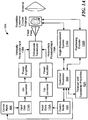
- FIG. 1A is a first illustrative system block diagram depicting a first half of a millimeter-wave based communications system 10A, usable at least with the communications link of FIG. 2 , the methods of FIGs. 10-12 , and the computer system of FIG. 14 , configured to dynamically control the operating point to reduce cross channel interference, in accordance with one embodiment.
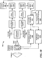
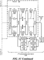
- FIG. 1B is a second illustrative system block diagram depicting a second half of the millimeter-wave based communications system 10A of FIG. 1A , usable at least with the communications link of FIG. 2 , the methods of FIGs. 10-12 , and the computer system of FIG. 1C4 , configured to dynamically control the operating point to reduce cross channel interference, in accordance with one embodiment;
- the combined system is a millimeter wave communication system, which general operates at far lower frequency (and therefore far longer wavelengths) than an optical communication system.
- visible light is not suitable for long-range free-space communication because visible light is strongly scattered by the dust, fog, and rain due to its short wavelength.
- Millimeter-wave are far less susceptible to scattering.
- FIG. 1C illustrates an exemplary system 10B in which at least one disclosed embodiment is implemented.
- the systems 10A and/or 10B each provide a simplified representation of a system 10B in which the disclosed communications link 100 (see FIG. 2 , described further herein) can operate, and that various electronics subsystems and other components (e.g., amplifiers, local oscillators mixers, power supplies, feed horns) that are known and understood by those in the art, are (for simplification) not depicted in FIG. 1C or elsewhere herein.
- the systems 10A, 10B of FIGs. 1A-1C are each in block diagram form and each does not illustrate direction or orientation of the signals being transmitted (although direction and orientation information is provided in other figures herein).
- the system 10B includes first and second communications link platforms, 101A, 101B, which include respective communication nodes 48A, 48B, respectively, that communicate over free space 103.
- the communications link platforms 101A, 101B are in motion, but this is not required for any embodiments.
- at least one embodiment is implemented where at least one of the communications link platforms 101A, 101B is in motion relative to the other, such as an aircraft in motion.
- the first communications link platform 101A includes a first polarizer 102 configured as part of a transmitter 106.
- a controller/processor 50A (described further herein in connection with FIG. 1C4 ) is in operable communication with the transmitter 106 and is configured to transmits input data 114A from the communication node 48A to a signal source 112 (which can be any type of signal generator, as will be understood, especially, in one embodiment, a millimeter wave (mmW) source), and controls the light/signal source to emit the first and second light/signal sources outputs 113A, 113B.
- a signal source 112 which can be any type of signal generator, as will be understood, especially, in one embodiment, a millimeter wave (mmW) source
- the controller/processor 50A also is in communication with a first data source 62A of stored information relating to the transmitter wave plate 102 and the transmitter 106; this first data source 62A need not be part of the first communications link 101A. It also will be appreciated that the input data 114A, although shown as originating from the communication node 48A, also could instead originate from the controller/processor 50A, or from another client or server outside of the system 10, or from any device or entity capable of providing input data (including a user at a terminal or other device capable of transmitting input data 114A).
- the system 10A starts with two independent data streams. Each is impressed onto a millimeter-wave (mmW) carrier to produce two independent linearly-polarized signals with orthogonal polarizations.
- mmW millimeter-wave
- the two orthogonally-polarized mmW signals are combined into a single physical channel by an orthomode transducer.
- single physical channel it is meant, in one aspect, to be occupying the same space, for example the two orthogonal linearly polarized signals propagate in a single circular waveguide, for example.
- the combined signals then enter a horn antenna equipped with a rotatable quarter-wave plate (or polarizer), which converts the orthogonal linearly-polarized signals to orthogonal circularly polarized signals.
- the output of the horn antenna illuminates a high-gain reflector antenna, which transmits the circularly-polarized signals to the receiver.
- the second communication node 48B receives the transmitted, converted data 132.
- the second controller/processor 50B also is in communication with a second data source 62B of stored information relating to the receiver wave plate 104 and the receiver 108; this second data source 62B need not be part of the second communications link 101B, but rather can be in operable communications with the second communications link 101B.
- the received transmitted, converted data 132 can, in one embodiment, be received at the controller/processor 50B.
- FIG. 4B is a high level flow chart showing operation of the system of FIGs. 1 and 2 , in accordance with one embodiment.
- FIG. 4B refers, in certain blocks, to processes discussed further in later figures in this application.
- two independent data streams from the first communication node 48A (block 1030), are provided to a signal source 112 (block 1040) to be converted to first and second signal source outputs 113A, 113B that are received at a linear polarizer 110.
- each source comprises a modulator, which impresses the data stream onto a mmW carrier at a low power level, followed by a power amplifier which amplifies the modulated signal to a high power level for transmission through free space.
- a separate linear polarizer is not required.
- the modulated mmW signal is by its nature linearly polarized before and after amplification to high power levels. Each modulated mmW signal is launched into rectangular waveguide, which preserves the linear polarization prior to combining the two signals at the orthomode transducer.
- the linear polarizer 110 converts the first and second signal outputs 113A, 113B, to two linearly polarized signals 11A8A, 118B (block 1050), which are transmitted through the linear polarizer 110 and then are provided to the polarizer 102 in the transmitter 106.
- the quarter wave plate/polarizer 102 converts the two linearly polarized signals 118A, 118B, to respective right and left hand circularly polarized signals RHCP 122A, LHCP 122B (block 1060). That is, the quarter wave plate/polarizer 102 is a device that can convert linear polarization to circular polarization. Although such a device might take many forms, in at least one embodiment such a device is referred to as a quarter-wave plate.
- the RHCP 122A and LHCP 122B signals are combined (e.g., at the orthomode transducer 123A, or another signal combiner) (block 1070) and transmitted across free space 103 (block 1080) to the corresponding orthomode transducer 123B at the receiver 108 (block 1090) at the second communications link platform 101B.
- the corrugated feed horn described herein is near the end of the signal path, where, together with the quarter-wave plate, it generates orthogonal circularly polarized signals that illuminate a high-gain reflector antenna that transmits the two signals to the receive. r (This communication of signals also is described further in connection with FIG. 2 ).
- the transmitted signal 125 is received at the second orthomode transducer 123B (block 1090), which is used to separate the polarized signals.
- the second orthomode transducer 12B thus converts the incoming transmitted signal 125 into a pair of received circularly polarized signals 122A' and 122B' (block 1100), which are provided to the receiver 108 polarizer 104 (or, in some embodiments, quarter wave plate), which itself converts the received circularly polarized signals 122A' and 122B' into a respective pair of linearly polarized output signals 124A, 124B (block 1110).
- the linearly polarized output signals 124A, 124B are received at the analyzer 125 and detector 130 and the data traverses the same path as the transmit path, except it is traversed in reverse order (block 1120), and this received data is provided, in one embodiment, to the 2 nd communication node 48B (block 1130) or another data recipient (e.g., the controller/processor 50B, or any other entity capable of receiving the data stream).
- FIG. 1C illustrates that the received data 132 is provided to the second controller/processor 50B, that is merely illustrative and not limiting.
- the received data 132 could, for example, be provided to a different controller/processor 50 outside the system 10, or to a memory device (not shown), or provided to a user via audio output, user display, or any other system or device, etc., as will be appreciated.
- Each communications link platform 101A, 101B also has a respective positioning encoder 120A, 120B, which is controlled, in this exemplary embodiment, by the respective controller/processor 50A, 50B.
- the positioning encoders 120A, 12B (120B?) are in operable communication with the respective polarizers (or wave plates) 102, 104 and used to rotate/adjust the respective polarizers (or quarter wave plates) 102, 104 (blocks 1020 and 1030 of FIG. 4B ).
- other positioning devices may be used to control the positioning encoder 120A, and that use of the controller/processors 50A, 50B respectively is illustrative and not limiting.
- a motor (not shown) with an encoder is used to control angular orientation of the polarizer.
- other devices may be used to rotate/adjust the respective polarizers/quarter wave plates 102, 104, instead of or in addition to the positioning encoders 120A, 120B.
- each communications link platform 101A, 101B has a respective angle measurement system 116A, 116B usable to measure quantities such as the rotation angle of the respective polarizer 102, 104 (or quarter wave plates), and the received signal vectors, as is explained further herein.
- the aforementioned encoder measures the rotation angle of the polarizer.
- block 1000 describes a high level step of calibrating the communications system and determining the misalignment-corrected polarizer rotation angles ⁇ 1 and ⁇ ' 2 , which angles are provided to the transmitter and receiver in block 1010.
- an optional block 1130 includes a process to optimize the operating point of the communication system 100, especially if the channel-to-channel isolation is insufficient; this process is explained more fully in connection with FIG. 13 .
- blocks 100 and 1010 are repeated at each update interval. This is explained further herein.
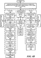
- FIG. 2 illustrates in greater detail an exemplary point-to-point communications link 100 utilizing the first and second polarizers 102, 104, respectively, at both transmitter 106 and receiver 108, in accordance with one embodiment.
- This communications link 100 can, for example, be implemented as part of the systems 10A, 10B of FIGs. 1A-1C , as will be appreciated, but is not so limited.
- the first and second polarizers 102, 104 also can be used to help model actual systems (e.g., based on systems 10A, 10B of FIGs. 1A- 1C ) that include a corrugated horn and polarizer combination (e.g., a horn antenna and reflector, etc., as will be understood in the art).
- a corrugated horn and polarizer combination e.g., a horn antenna and reflector, etc., as will be understood in the art.
- the first polarizer 102 and the transmitter 106 convert two linearly polarized input signals 118A, 118B to right hand circularly polarized (RHCP) (clockwise) and left hand circularly polarized (LHCP) (counter-clockwise) signals 122A, 122B, respectively.
- RHCP right hand circularly polarized
- LHCP left hand circularly polarized
- FIG. 2 depicts only the transmitted signal 125 of FIGs 1A-1C , as transmitted through free space.
- the polarizer 104 at the receiver 108 converts incident RHCP and LHCP signals 122A' and 122B' back into two orthogonal linear polarization signals 124A, 124B, respectively (see FIGs 1A-1C ).
- Polarization diversity can be exploited to double the information-carrying capacity of a point-to-point communications link 100, like that depicted in FIGs. 1 and 2 .
- angular alignment between the transmitter 106 and receiver 108 cannot be assumed, limiting the usefulness of linear polarization. If the transmitted signals are circularly polarized, however, they can be recovered by the receiver 108 regardless of the orientation angle ⁇ of the receiver 108 with respect to the transmitter 106.
- signal transmission and recovery requires two polarizers in the form of quarter-wave plates 102, 104 one at the transmitter 106, and one at the receiver 108.
- FIG. 3 depicts an exemplary quarter-wave plate with axes along x and y directions, in accordance with one embodiment. Referring to FIGs.
- angles ⁇ 1 and ⁇ 2 ′ are independent of the value of ⁇ , and need not be adjusted to compensate for changes in ⁇ with time due to variations in the relative orientation of the receiver with respect to the transmitter (due to platform motion, for example).
- real quarter-wave plates are not ideal. Attenuation is non-zero and depends on polarization, the relative phase shift is not 90°, and both attenuation and phase shift are frequency dependent.
- the isolation also is not perfect. Note that isolation for a real quarter-wave plate depends at least in part on quarter-wave plate departure from ideal and on relative orientation between transmitter and receiver.
- one or more methods are provided that provide ways to compensate, at least partially, for the non-ideal behavior of real-world quarter-wave plates and linear-to-circular polarizers in general, allowing for their use in various systems, including but not limited to wideband millimeter-wave communication systems that utilize polarization diversity to realize increased data rates.
- a wave plate has a pair of orthogonal axes (e.g., the x and y axes shown in FIG. 3 ) having characteristic complex transmission coefficients for linearly polarized incident waves;
- E x out T x e ⁇ j ⁇ x E x in
- E y out T y e ⁇ j ⁇ y E y in
- T x and T y are the real transmission coefficients (accounting for reflection and ohmic losses)
- ⁇ x and ⁇ y are the corresponding phase shifts.
- wave plates will have different transmission amplitudes and phases along the two axes x, y, as shown in Equations (1a) and (1b) above.
- FIGs. 1 and 2 depict embodiments of an exemplary free-space communication link 100.
- the transmitter 106 generates two orthogonal linearly-polarized information-bearing signals 118A, 118B.
- the electric-field vectors of the two signals are aligned with the transmitter 106 polarization axes (designated "1" and "2" in FIG. 2 ). That is, the first signal 118A of the two orthogonal linearly-polarized information bearing signals is polarized along axis 1 and the second signal 118B is polarized along axis 2.
- the two signals 118A, 118B are combined into a transmitted signal 125 (e.g., at the first orthomode transducer 123A (orthomode transducers also are known as a polarization duplexers)), and transmitted across free space 103 to the receiver 108. There also is a step of conversion to circular polarization, as described herein.
- FIG. 2 depicts two sets of polarization axes at the receiver: axes 3 and 4. Axes 3 and 4 are aligned with transmitter 106 axes 1 and 2, respectively. FIG. 2 also shows axes 3' and 4', which are rotated by an angle ⁇ with respect to receiver axes 3 and 4.
- the angle ⁇ also referred to as misalignment angle
- misalignment angle is used to quantify any angular misalignment between transmitter and receiver (thus, the smaller the angle ⁇ , the better the alignment between transmitter 106 and receiver 108).
- this misalignment angle is estimated, based at least in part on measured/stored polarizer 102, 104 performance parameters and actual measured transmitter 106 and receiver 108 polarizer 102, 104 rotation angles (this is discussed further herein in connection with FIG. 10 ).
- the transmitted signals are circularly polarized, having been converted from linear to circular polarization by the transmitter's polarizer/quarter-wave plate.
- the two orthogonal linearly-polarized information bearing signals 118A, 118B, sent together as a transmitted signal 125 must be separated by the receiver 108 (e.g., via the 2 nd orthomode transducer 123B) with minimal cross-channel interference.
- FIG. 3 provides another illustration showing, in one figure, transmitter 106 polarization axes 1 and 2 and receiver 108 polarization axes 3' and 4'.
- the communications link 100 in one embodiment, is implemented using non-ideal, but identical quarter wave plates 102, 104 at the transmitter 106 and receiver 108, respectively.
- the real-time transmission coefficient T for the wave plates 102, 104 also might not be identical in both the x and y direction and also can deviate from the "ideal" value of 1 (which would mean 100% of light is transmitted).
- the differential phase shift ⁇ x - ⁇ y 85°
- the transmitter-receiver misalignment angle ⁇ 30°.
- Circular polarization can be utilized to mitigate the effects of angular misalignment between the receiver 108 and the transmitter 106.
- the first linearly polarized input signal 118A (“signal 1”) (polarization 1) is converted to right-hand circular polarization (RHCP) 122A and the second linearly polarized input signal 118B (“signal 2”) (polarization 2) is converted to left-hand circular polarization 122B, prior to transmission.
- RHCP right-hand circular polarization
- polarization 2 polarization 2
- the receiver 108 can distinguish RHCP from LHCP regardless of the relative rotation angle ⁇ between transmitter 106 and receiver 108 polarization axes.
- a first polarizer 102 is needed at the transmitter 106 to convert linear to circular polarization prior to transmission.
- a second quarter-wave plate 104 is needed at the receiver 108 to convert the transmitted right- and left-hand circularly polarized signals 122A', 122B', back to their corresponding linear polarizations 124A, 124B.
- the transmitter wave plate 102 is oriented at an angle ⁇ 1 with respect to the transmitter polarization axes x and y.
- the transmitter wave plate 102 takes the two orthogonal linearly-polarized input signals 118A, 118B and converts the first linearly polarized input signal 118A to right-hand circular polarization (RHCP) 122A and the second linearly polarized input signal 118B to left-hand circular polarization (LHCP) 122B, for transmission to the receiver 106.
- the second wave plate 104 converts the incident circularly-polarized waves 122A', 122B', back to two orthogonal linearly polarized signals 124A, 124B. Note that the linearly-polarized signal components at the receiver 104 need not be parallel to their transmitted counterparts. For interference-free reception, in one embodiment, the linearly-polarized signal components at the receiver 102 need to be parallel to the rotated receiver polarization axes 3' and 4'.
- x and y refer to the axes of the wave plate
- angle ⁇ 1 is the rotation angle of the x-axis of the wave plate with respect to polarization axis 1 of the transmitter 102.
- an ideal quarter-wave plate converts the signal whose electric field vector is parallel to polarization axis 1 into RHCP, and the signal whose electric field vector is parallel to polarization axis 2 into LHCP.
- the amplitude of the RHCP component is due entirely to signal 1 and the LHCP component is due entirely to signal 2.
- the rotation matrix generates the polarization components of the received wave along the receiver 108 axes 3' and 4', which are rotated by an angle ⁇ with respect to those of the transmitter 106;
- the matrix elements A 2 - D 2 are identical in form to A 1 - D 1 in Equations (3a-3d), but with ⁇ 2 in place of ⁇ 1 .
- Both B T and C T depend on trigonometric functions of the angles ⁇ 1 and ⁇ 2 .
- B T 0, there are multiple solutions for the angles ⁇ 1 and ⁇ 2 due to the periodic nature of the trigonometric functions.
- the integers n and m quantify this underlying periodicity, as will be appreciated.
- the difference between the two orientation angles ⁇ 1 and ⁇ 2 ′ generally will be an odd multiple of 90°.
- the transmitted signals 1 and 2 polarized parallel to transmitter polarization axes 1 and 2, respectively
- corresponding to linearly polarized inputs 118A, 118B in FIG. 1C are recovered at the receiver 108 even if the receiver 108 polarization axes are not parallel to those of the transmitter 106.
- No knowledge of the receiver 108 orientation relative to the transmitter 106 is needed, which is a motivation for using circular polarization.
- FIGs. 5A-5B provide an exemplary contour plot of two-channel isolation as a function of the transmitter and receiver quarter-wave plate rotation angles as referenced to the transmitter 106 of FIGs. 1 and 2 , where FIG. 5A is a plot of the isolation over the range 0 ⁇ ⁇ 1,2 ⁇ 180°, and shows approximate location range 80 of ideal operating point 82.
- FIG. 5B shows more clearly the area around the ideal operating point 82 ( ⁇ 1 , ⁇ 2 ), in accordance with one embodiment.
- FIGs. 5A and 5B show receiver channel isolation as a function of the rotation angles ⁇ 1 and ⁇ 2 when the wave plates (e.g., quarter wave plates 102 and 104 of FIG. 2 ) are non-ideal.
- the process starts at the transmitter with two orthogonal linearly polarized signals bearing independent data streams. They are combined into a single beam by the orthomode transducer and converted to RHCP and LHCP (slightly elliptical in reality) by the wave plate.
- each signal has a linearly-polarized component along the desired direction and a component along the orthogonal direction after passage through the receiver wave plate. It is the component along the orthogonal direction that represents interference or crosstalk, as it is aligned with and will interfere with the other channel.
- These undesired interfering signal components are represented by the matrix elements B T and C T in Eq. 4.
- isolation in either receiver channel is defined here as the ratio of the desired channel to that of the undesired channel. This is explained further herein in connection with FIG. 1C3 .
- the worst-case isolation is plotted at each point (in particular, the minimum channel isolation mi n[ I 1 ( ⁇ 1 , ⁇ 2 ), I 2 ( ⁇ 1 , ⁇ 2 )] is plotted at each point ( ⁇ 1 , ⁇ 2 )).
- the x-axis is the rotation angle ⁇ 1 of plate 1 of FIG. 2 (i.e., the polarizer 102 at transmitter 106)
- the y-axis is the rotation angle ⁇ 2 of plate 2 of FIG. 2 (i.e., the quarter wave plate 104 of receiver 108).
- the impact of the non-ideal wave plate performance is a shift in location of the region of maximum isolation from the location of the ideal operating point.
- the isolation at the first ideal operating point 84 (which is within the ideal operating point range 80) is about 27.14 dB, using "real" quarter-wave plates.
- This isolation of 27.14 dB at the first ideal operating point 84 is insufficient, in one embodiment, for a high-speed communication link using high-order modulation techniques (e.g., 32-QAM) and requiring 30 dB or more isolation.
- High-order modulation schemes such as QAM-32, QAM-64, etc. pack more and more information into each transmitted symbol by sacrificing immunity to interference and noise, and sufficiency of isolation will be well understood by those in the art.
- the ideal operating point is given by Eqs. 5a and 5b; it is the operating point under ideal conditions when using ideal wave plates.
- the optimal operating point is the point of maximal isolation when real, non-ideal waveplates are used. In the example given here, the optimal operating point is found by calculating the isolation as a function of the angles ⁇ 1 and ⁇ 2 and finding the peak value. In practice, one would use approximate or iterative techniques, as described below.
- a significant performance benefit is gained by operating at or near the optimal operating point 82.
- the wave plates 102, 104 are of high quality, i.e., having low transmission losses (that is, T x and T y are reasonably close to unity) and
- all that is required to compute the approximate operating point 86 is the angle ⁇ , (also referred to herein as wave plate phase shift error) which is a known property of the wave plates obtained via measurement, and the angle ⁇ , which must be determined periodically during operation.
- FIG. 5A-5B and 6 graphically illustrate the effectiveness, in one example embodiment, of at least one of the polarization compensation methods described herein, which methods apply at least one polarization compensation algorithm discussed herein, in accordance with one embodiment, but only for a single set of quarter-wave plate parameters, for a single value of the orientation angle ⁇ , and under the assumption that the non-ideal transmitter and receiver quarter-wave plates are assumed identical.
- the differential phase shift ⁇ x - ⁇ y may be significantly different than 90°
- the quarter-wave plates 102, 104 may be subject to finite manufacturing tolerances and may be slightly different (versus being identical to teach other).
- FIGs. 7-9 present the results of a series of Monte-Carlo simulations in which the quarter-wave plate parameters were allowed to vary randomly over a large number (10 6 ) of trials. This helps, for at least some embodiments, to simulate various combinations of non-ideal wave plates.
- the range of variation is small.
- the transmitter and receiver wave plates are assumed here, for at least some embodiments, to be of identical design.
- the random variations are "noise" due to manufacturing tolerances which result in non-identical performance for the two wave plates. If manufacturing standards are high, tolerances will be tight and performance variations small.
- each parameter is represented by a uniformly distributed random variable that varies over the range specified below:
- T x 1 0.95 ⁇ 0.02
- T x 2 T x 1 ⁇ 0.002
- each plot in FIGs. 7-9 represents a different value of the transmitter-receiver misalignment angle ⁇ (e.g., 0°, 20°, 37.5°), and illustrates uncorrected (top) and corrected (bottom) isolation.
- ⁇ e.g., 0°, 20°, 37.5°
- the worst-case channel isolation is calculated at the approximate operating point ( ⁇ 1 , ⁇ 2 ′ ) given by Equation (9); for the uncorrected isolation, the correction angle ⁇ is set equal to zero for all trials.
- the minimum isolation out of 1 million trials is 35.1 dB.
- performance degrades.
- ⁇ exceeds approximately 20° (as shown in FIG. 7 )
- the minimum isolation falls below 30 dB.
- the percentage P fail of trials whose isolation falls below 30 dB increases rapidly, surpassing 10% when ⁇ ⁇ 37.65°. That is, the yield of quarter-wave plate pairs falls below 90% as ⁇ surpasses 37.65°.
- a method for determining and applying compensation for non-ideal quarter-wave plate performance and transmitter-receiver angular misalignment is provided. Note that, for some embodiments, correction is not needed for relatively small misalignment angles (e.g., misalignment angles that are 10° or smaller) and reasonable quarter wave plate performance. For larger misalignment angles (e.g., misalignment angles greater than 10°), more frequent polarizer calibration and angular correction is needed, e.g., periodic calibration/correction, for at least some embodiments.
- FIG. 10 is an illustrative flow chart of a method for determining at least one appropriate operating point, usable with the systems of FIGs. 1A-FIG. 1C and the communications link of FIG. 2 , in accordance with one disclosed embodiment.
- FIG. 11 is an illustrative flow chart of a method, usable with the method of FIG. 10 , for computing receiver quarter-wave plate rotation angle ⁇ 2 with respect to transmitter polarization axes, in accordance with one embodiment.
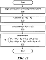
- FIG. 12 is a flow chart of a method, usable with the method of FIG. 10 , for computing misalignment angle ⁇ , in accordance with one embodiment.
- the misalignment angle is not measured directly, but is obtained from measurements of ⁇ 2 and ⁇ 2 ' (see Eq. 15).
- angles that can be measured directly are ⁇ 1 and ⁇ 2 ′ ; ⁇ 2 must be calculated from the known (e.g., measured) angles and wave plate properties, and is in turn used to calculate an estimated ⁇ .
- These angles are relative to the transmitter and receiver polarization axes, respectively, which are fixed with respect to the transmitter and receiver. Using polarization axes as fixed baselines for angular measurements, the angles can be directly measured by the wave plate motor encoders, for example. Angles ⁇ 1 and ⁇ 2 ' are measured by the encoders on the wave plate rotation motors, for example.
- the method of FIG. 10 repeats, for each update interval, where an update interval is defined as the time between updates in alignment of the transmitter 106 wave plate 102 and receiver 108 wave plate 104.
- the frequency and duration of these periodic updates depend on a number of things, such as motion and vibration of the platforms to which the transmitter and receiver are attached.
- updating is done on a regular schedule, such as periodically (e.g., every 100 milliseconds (ms).).
- updating occurs based on predetermined action triggering a need for updating, measuring, and adjusting one or both of the quarter wave plates 102, 104.
- Illustrative examples of actions, events, or conditions that might result in a need to update and adjust include, but are not limited to, a specific user request, a specific action in the system, detection of an error, detection that channel to channel isolation is not meeting a predetermined requirement or standard, establishment of a new communications link with a new communication platform, a detection of a change in position of one of the two ends of a communication link, a regular schedule whose update rate can be increased under adverse conditions. etc.).
- the subscripts "1" and “2" denote wave plates 1 and 2 (e.g., the transmitter wave plate 102 and the receiver wave plate 104 in FIGs. 1-2 ) and are included to emphasize that the wave plates need not be identical. All that is required is knowledge of their properties, which properties can be determined in advance, such as by measurement or retrieval of stored data (e.g., as provided by a manufacturer), etc., as will be understood in the art.
- the factor K is a (previously omitted) complex factor accounting for phase and attenuation due to propagation from the transmitter to the receiver.
- Q 1 Q 2 A 1 B 1 C 1 D 1 E 1 E 2
- Q 3 ′ Q 4 ′ T x ⁇ 1 e j ⁇ x 0 0 T y ⁇ 1 e j ⁇ y 2 cos ⁇ 2 ′ sin ⁇ 2 ′ ⁇ sin ⁇ 2 ′ cos ⁇ 2 ′ E 3 ′ E 4 ′
- K is a complex factor that accounts for propagation delay and attenuation between the transmitter and the receiver. Its value (the value of K) depends on the gain of the transmitting and receiving antennas, atmospheric conditions, and the distance between transmitter and receiver. Since the value is the same for both polarizations, its actual value is not important for at least some embodiments.
- the modified transmitted and received signal vectors [ Q 1 , Q 2 ] and Q 3 ′ Q 4 ′ , respectively, are entirely determined by directly measured quantities and can be used to determine the angle ⁇ 2 .
- tan ⁇ 2 Q 3 ′ Q 4 ′ ⁇ Q 1 Q 2 1 + Q 1 Q 3 ′ Q 2 Q 4 ′ .
- misalignment angle ⁇ ⁇ 2 ⁇ ⁇ 2 ′
- misalignment angle is not directly measured and is derived from ⁇ 2 , which itself is not directly measured.
- the ambiguity can be resolved by constraining the relative orientations of the transmitter and receiver.
- the receiver 108 it can be required that the receiver 108 be "upright" relative to the transmitter 106 in that -90° ⁇ ⁇ ⁇ 90°; to resolve the ambiguity, choose the value of ⁇ 2 so that the resulting value of ⁇ satisfies -90° ⁇ ⁇ ⁇ 90°. This is not the only way to resolve the ambiguity, as will be understood in the art.
- this process starts, at each update interval (block 200), by measuring the transmitter quarter-wave plate rotation angle ⁇ 1 (from the output of the positioning motor encoder 120A, for example) and communicating the value of ⁇ 1 to the receiver 108 (block 215).
- the receiver quarter-wave plate rotation angle ⁇ 2 ′ ⁇ 2 ⁇ ⁇ is measured (block 220). Note that the actions in blocks 215 and 220 need not be performed in the exact order listed in FIG. 10 .
- the known properties of the transmitter 106 and receiver 108 wave plates e.g., from a stored set of those properties (block 230) are retrieved/received (block 225).
- the value of (the receiver quarter-wave plate rotation angle with respect to the transmitter polarization axes) is calculated (block 225 and FIG. 11 ).
- FIG. 11 is a flow chart of a method, usable in connection with the method of FIG. 10 , for computing receiver quarter-wave plate rotation angle ⁇ 2 with respect to transmitter polarization axes, in accordance with one embodiment.
- the known properties (block 505) of the transmitter 106 and receiver 108 wave plates 102, 104, respectively, as well as the measured value of the transmitter 108 polarizer 102 rotation angle ⁇ 1 are used to compute the transmission matrix coefficients A 1 - D 1 (block 515).
- To perform a relative phase calibration between the two receive channels note that only one is shown in FIGs.
- a reference signal is transmitted on channel 1 from the transmitter 106 to the receiver 108(block 520), where the polarization of channel 1 is parallel to the transmitter 106 polarization axis 1.
- this can be done by transmitting a single linearly-polarized transmit signal at a 45 degree inclination (block 525).
- FIG. 1C shows two linearly polarized inputs, which represent two channels each carrying an independent data stream. The wave plate converts these to RH and LH circular polarization before transmission to the receiver.
- Figure 2 is used to illustrate receiver-transmitter geometry, and does not reference the number of channels.
- This calibration signal has a known polarization, and the receiver 108 knows what the known polarization of the calibration signal should be, based, in one embodiment, on a pre-determined calibration protocol.
- a determination can be made about what is the relative orientation between the transmitter 106 and the receiver 108.
- the orientations of the transmitter wave plate with respect to the transmitter polarization axes can be measured directly.
- the same is true of the receiver wave plate.
- the relative orientation between the transmitter and receiver is required, in one embodiment, to determine the orientation between the transmitter and receiver wave plates. This is explained further below. Note also that, in at least some embodiments, phase calibration is not necessary.
- the received signal vector E 3 ′ E 4 ′ is measured by the receiver (block 530).
- the receiver hardware can make this measurement; the components of the received signal vector can be extracted from the received data stream after demodulation.
- tan ⁇ 2 is computed as shown in block 550.
- ⁇ 2 tan -1 (tan ⁇ 2 ). This value of ⁇ 2 is returned for the next blocks in FIG. 10 .
- FIG. 12 is a flow chart of a method, usable with the method of FIG. 10 , for computing misalignment angle ⁇ , in accordance with one embodiment.
- misalignment angle ⁇ (block 600)
- ⁇ 1 ⁇ 2 ⁇ ⁇ 2 ′ , (block 610).
- ⁇ 2 ⁇ 2 + ⁇ ⁇ ⁇ 2 ′ , (block 620).
- ⁇ can be determined (block 630).
- ⁇ 2 ⁇ 2 + ⁇ ⁇ ⁇ 2 ′ if ⁇ ⁇ / 2 ⁇ ⁇ 2 ⁇ ⁇ / 2 .
- the misalignment angle ⁇ is relatively small (e.g., smaller than some predetermined value, which in one embodiment is 10°)
- correction e.g., computation of the rotation of quarter wave plates
- transmission coefficients are close to 1 and a differential phase shift
- ⁇ 1 2 n + m + 1 ⁇ 4 + ⁇ 2
- ⁇ 2 ′ 2 n ⁇ m ⁇ 1 ⁇ 4 ⁇ ⁇ 2 .
- n and m are integers and are derived as explained above.
- the updated rotation angle ⁇ 1 is transmitted to the transmitter 106 (block 270), and the transmitter 106 polarizer 102 is rotated (e.g., via a command sent from controller/processor 50A to positioning encoder 120A) to the angle ⁇ 1 (block 280).
- receiver 108 quarter wave plate 104 is rotated to angle ⁇ ' 2 (block 290).
- these computations are carried out at the transmitter, so no transmission of an updated rotation angle is necessary.
- the transmitter polarizer 102 and the receiver quarter-wave plate 104 remain (block 315) at the positions to which they are rotated (blocks 300-315), so long as communication continues (block 310) or until the next update interval occurs (block 300).
- the transmitter 106 polarizer 102 and receiver 108 quarter wave plate 104 may be further rotated/adjusted if channel to channel isolation is insufficient.
- Update intervals are dependent in at least one embodiment on the system requirements; an exemplary update interval in one embodiment is every 100 ms.
- the update interval should be as long as possible, because, in these embodiments, whenever the systems 10A, 10B is transmitting calibration signal, it is not communicating (that is, the data stream stops).
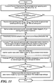
- FIG. 13 is a flow chart of a second exemplary method for determining appropriate operating point, which method is usable with at least some embodiments, including at least the systems of FIGs. 1A-1C and the communications link of FIG. 2 , in accordance with one embodiment.
- the exemplary method of FIG. 13 determines a suitable operating point using a iterative search algorithm, which in this example uses the ideal operating point (Equation (5)) or the approximate operating point (Equation (9)) as a starting point.
- the channel to channel isolation at the "approximate" operating point (see blocks 255-260 of FIG. 10 , described above, as well as equations 5A-5B, 6A, 6, and 10 and FIGs. 5A, 5B , and 6 , is computed (or received) (block 700). If the isolation at the approximate operating point is sufficient (e.g., satisfies a predetermined requirement) (block 710), then no further processing is necessary, and the method ends.
- 64-QAM requires a signal-to-noise ratio (SNR) of 28 dB to achieve a bit-error rate (BER) of 10 -8 or less (i.e., fewer than 1 in 10 8 bits is in error).
- SNR signal-to-noise ratio
- BER bit-error rate
- 128-QAM requires an SNR of 32 dB to achieve a comparable BER.
- processing moves to block 720, where, as a starting point/goal, information is received (block 725) about rotation angles ⁇ 1 and ⁇ 2 ′ that correspond to one of the ideal operating point (Equations 5A, 5B) or the approximate operating point (Equations 9A, 9B), or some other "stored point" usable as a starting point.
- the rotation angles ⁇ 1 and ⁇ 2 ′ , of the transmitter 106 and receiver 108 quarter-wave plates 102, 104 are set to positions that correspond to a starting point (e.g., the current angles ⁇ 1 and ⁇ 2 ′ at which the plates are set, or the settings that correspond to the ideal or approximate operating point) (block 730). This step may be skipped if the transmitter 106 and receiver 108 quarter-wave plates already are at a desired starting point.
- a predetermined calibration data stream is sent from the transmitter 106 to the receiver 108, at one linear polarization only (block 750). Then, a 1 st ratio is computed (block 750), of received signal strength in the designated receive channel (corresponding to the polarization of the calibration data stream) to that in the orthogonal channel.
- the transmitter and receiver quarter-wave plate rotation angles ⁇ 1 and ⁇ 2 ′ angles are iteratively adjusted, as dictated by the search algorithm, the goal being to maximize the two-channel isolation (block 760). That is, the search algorithm seeks out the quarter-wave plate rotation angles ⁇ 1 and ⁇ 2 ′ that maximize the ratio of the received signal strength in the designated receive channel. For example, after each iteration adjustment, a 2 nd ratio is computed (block 770) to see if the ratio is improved as compared to the 1 st ratio
- FIG. 14 shows a block diagram of a computer system 50 usable with at least some embodiments, including at least the communications link of FIG. 2 the methods of FIGs. 10-13 , and the system block diagrams of FIGs. 1A-1C , in accordance with one embodiment.
- the computer system 50 can be used to implement the controller/processor 50A and/or the controller processor 50B of FIGs. 1A-1C .
- the computer system 50 also can be used to implement all or part of any of the methods, equations, and/or calculations described herein.
- systems and methods in accordance with at least some embodiments can be implemented using any type of computer system running any one or more types of operating systems.
- Exemplary types of computer systems on which at least some embodiments can be embodied include any system or device having a processor (or equivalent processing functionality) installed or embedded, including but not limited to a desktop computer, personal computer (PC), laptop computer, notebook computer, tablet computer, handheld computer, netbook, personal digital device (including but not limited to personal digital assistant (PDA), mobile communications device (including but not limited to radio, conventional telephone, mobile/cellular telephone, smart phone, combination phone-tablet computer, music playing device, electronic reading device) server, workstation, and interconnected group of computers, as well as any other type of device having a microprocessor installed or embedded thereto, such as a field-programmable gate array (FPGA).
- FPGA field-programmable gate array
- the exemplary computer system 50 of FIG. 14 includes a central processor 1, associated memory 2 for storing programs and/or data, an input/output controller 3, a disk controller 4, a network interface 5, a display device 7, one or more input devices 8, a fixed or hard disk drive unit 9, a removal storage device/drive (optional) 13, optionally a backup storage device (e.g., a tape drive unit) (not shown) and a data bus 6 coupling these components to allow communication therebetween.
- the central processor 1 can be any type of microprocessor, such as a PENTIUM-family processor, made by Intel of Santa Clara, California.
- the display device 7 can be any type of display, such as a liquid crystal display (LCD), plasma display, cathode ray tube display (CRT), light emitting diode (LED), and the like, capable of displaying, in whole or in part, any desired information.
- the input device 8 can be any type of device capable of providing the desired inputs, such as keyboards, numeric keypads, touch screens, pointing devices, switches, styluses, and light pens.
- the network interface 5 can be any type of a device, card, adapter, or connector that provides the computer system 50 with network access to a computer or other device, such as a printer.
- the network interface 5 can enables the computer system 50 to connect to a computer network such as the Internet.
- a computer network such as the Internet.
- Other computer accessories e.g., microphones, cameras, speakers, biometric access-control devices such as fingerprint scanners, etc., although not illustrated in the block diagram of FIG. 14 , can of course be included as part of the computer system 50.
- Computer systems embodying at least some embodiments described herein need not include every element shown in FIG. 14 .
- one or more computer programs define at least some of the operational capabilities of the computer system 50. These programs can be loaded into the computer system 50 in many ways, such as via the hard disk drive 9, the removable storage driver 13, or the network interface 5 (e.g., wirelessly, via the Internet, etc.). Alternatively, the programs can reside in a permanent memory portion (e.g., a read-only-memory (ROM)) chip) of the main memory 2. In another embodiment, the computer system 50 can include specially designed, dedicated, hard-wired electronic circuits that perform all functions described herein without the need for instructions from computer programs.
- ROM read-only-memory
- the computer system 50 is networked to other devices, such as in a client-server or peer to peer system.
- the computer system 50 can, for example, be a client system, a server system, or a peer system.
- at least one embodiment is implemented at the server side and receives and responds to requests from a client, such as a reader application running on a user computer.
- the client can be any entity, such as a the computer system 50, or specific components thereof (e.g., terminal, personal computer, mainframe computer, workstation, hand-held device, electronic book, personal digital assistant, peripheral, etc.), or a software program running on a computer directly or indirectly connected or connectable in any known or later-developed manner to any type of computer network, such as the Internet.
- a client may also be a notebook computer, a handheld computing device (e.g., a PDA), an Internet appliance, a telephone, an electronic reader device, or any other such device connectable to the computer network.
- the server can be any entity, such as the computer system 50, a computer platform, an adjunct to a computer or platform, or any component thereof, such as a program that can respond to requests from a client.
- the server also may include a display supporting a graphical user interface (GUI) for management and administration, and an Application Programming Interface (API) that provides extensions to enable application developers to extend and/or customize the core functionality thereof through software programs including Common Gateway Interface (CGI) programs, plug-ins, servlets, active server pages, server side include (SSI) functions and the like.
- GUI graphical user interface
- API Application Programming Interface
- software embodying at least some embodiments resides in an application running on the computer system 50. At least one embodiment is embodied in a computer-readable program medium usable with the general purpose computer system 50. At least one embodiment is embodied in a data structure stored on a computer or a computer-readable program medium. At least one embodiment is embodied in an application programming interface (API) or a user interface. In addition, at least one embodiment is embodied in a data structure.
- API application programming interface
- a user interface In addition, at least one embodiment is embodied in a data structure.
- the transmit and receive functions of the described systems 10A, 10B and communication link 100 are interchangeable on this structure. That is, everywhere in this description and in the figures referenced herein, the word receive is used it can be replaced with transmit and likewise transmit can be replaced by receive, should the application be better served by such an arrangement.
- the described circuits are usable for many different types of communications systems, optics transmission systems, and/or system that use any type of wave plate using any type of polarization, as will be appreciated.
Landscapes
- Engineering & Computer Science (AREA)
- Computer Networks & Wireless Communication (AREA)
- Signal Processing (AREA)
- Radio Transmission System (AREA)
- Optical Communication System (AREA)
Claims (15)
- Procédé d'émission de signaux d'un premier nœud de communication à un second nœud de communication, le procédé comprenant :la réception (1040) de premier et second flux de données destinés à être transmis par le premier nœud de communications ;la conversion (1050) des premier et second flux de données en premier et deuxième signaux orthogonaux polarisés linéairement ;la réception (1060) des premier et deuxième signaux orthogonaux polarisés linéairement au niveau d'un premier polariseur (102), le premier polariseur étant orienté à un premier angle de rotation, le premier polariseur convertissant les premier et deuxième signaux orthogonaux polarisés linéairement en, respectivement, un premier signal polarisé circulairement à droite, RHCP, et un premier signal polarisé circulairement à gauche, LHCP ;la combinaison (1070) du premier signal RHCP et du premier signal LHCP en un signal émis ayant une première intensité de signal et l'émission (1080) du signal émis à destination d'un récepteur au niveau du second nœud de communication, le récepteur comprenant un second polariseur (104) orienté à un second angle de rotation et configuré pour recevoir le signal émis ;l'ajustement du premier angle de rotation pour sensiblement augmenter l'isolement entre des troisième et quatrième signaux orthogonaux polarisés linéairement au niveau du récepteur, les troisième et quatrième signaux orthogonaux polarisés linéairement étant dérivés, respectivement, du signal émis reçu au niveau du récepteur, et correspondant, respectivement à des versions transmises des premier et deuxième signaux polarisés linéairement, l'ajustement étant basé au moins en partie sur une analyse en temps réel (1010) d'une perte d'émission des troisième et quatrième signaux orthogonaux polarisés dernièrement en comparaison au signal émis envoyé par l'émetteur, et des informations relatives au second angle de rotation du second polariseur ; etl'ajustement (1010) du premier angle de rotation sur la base au moins en partie d'un calcul d'un angle de désalignement entre les premier et second angles de rotation.
- Procédé selon la revendication 1 , comprenant en outre la fourniture d'informations pouvant être utilisées pour ajuster le second angle de rotation afin d'augmenter sensiblement l'isolement entre les troisième et quatrième signaux orthogonaux polarisés linéairement au niveau du récepteur, l'ajustement étant basé au moins en partie sur l'analyse en temps réel de la perte d'émission des troisième et quatrième signaux orthogonaux polarisés linéairement en comparaison au signal émis envoyé par l'émetteur.
- Procédé selon la revendication 1, dans lequel le calcul fournit une estimation de l'angle de désalignement.
- Procédé selon la revendication 1, dans lequel la détermination de l'angle de désalignement est basée au moins en partie sur une mesure en temps réel du premier et/ou second angle de rotation.
- Procédé selon la revendication 4, dans lequel la détermination de l'angle de désalignement est basée au moins en partie sur une propriété du premier et/ou second polariseur.
- Procédé selon la revendication 5, dans lequel les premier et second polariseurs sont des première et seconde plaques quart d'onde, le procédé comprenant en outre :
le calcul d'au moins un point de fonctionnement sur la base en partie du premier angle de rotation, du second angle de rotation et/ou d'au moins une propriété d'au moins une des première et seconde plaques quart d'onde, l'au moins un point de fonctionnement correspondant à un agencement d'angle de rotation d'émetteur et de récepteur configuré pour obtenir au moins un niveau prédéterminé d'isolement entre les troisième et quatrième signaux orthogonaux polarisés linéairement. - Procédé selon la revendication 6 dans lequel l'au moins un point de fonctionnement correspond à un agencement d'angles de rotation de polariseurs d'émetteur et de récepteur qui est configuré pour sensiblement maximiser le niveau d'isolement entre les troisième et quatrième signaux orthogonaux polarisés linéairement.
- Procédé selon la revendication 1 , dans lequel au moins un des premier et second nœuds de communication se déplace par rapport à l'autre des premier et second nœuds de communication.
- Procédé selon la revendication 1 , dans lequel les premier et second polariseurs sont des première et seconde plaques quart d'onde, et les premier et deuxième signaux orthogonaux polarisés linéairement sont orientés de manière à être parallèles aux axes orthogonaux de la première plaque quart d'onde ; ou
dans lequel les deuxième et troisième signaux orthogonaux polarisés linéairement sont orientés de manière à être sensiblement parallèle à des axes de polarisation tournés de la seconde plaque quart d'onde ; ou
dans lequel l'ajustement comprend l'ajustement dynamique du premier angle de rotation conformément à une fréquence de mise à jour périodique prédéterminée d'angle de rotation. - Procédé selon la revendication 1, comprenant en outre :la mesure du premier et/ou second angle de rotation ;l'étalonnage d'une phase entre les premier et deuxième signaux orthogonaux polarisés linéairement ;le calcul, sur la base au moins en partie d'une propriété du premier et/ou second polariseur et/ou d'une mesure du premier et/ou second angle de rotation, d'un angle de désalignement entre les premier et second polariseurs ;la détermination, sur la base au moins en partie de la propriété du premier et/ou second polariseur, de la mesure du premier et/ou second angle de rotation, et/ou de l'angle de désalignement, d'un angle de correction et d'une erreur de déphasage associés au premier et/ou second polariseur ; etla rotation du premier et/ou second polariseur à un premier ou second angle de rotation respectif sélectionné conformément à l'angle de correction et à l'erreur de déphasage, la rotation étant configurée pour compenser sensiblement au moins l'angle de désalignement et/ou l'erreur de déphasage entre les premier et second polariseurs.
- Système de communication (10B), comprenant :un générateur de signaux (110) configuré pour convertir des premier et second flux de données reçus en premier et deuxième signaux orthogonaux polarisés linéairement ;un premier polariseur (102) orienté à un premier angle de rotation et configuré pour être en communication opérationnelle avec le générateur de signaux, le premier polariseur étant configuré en outre pour convertir les premier et deuxième signaux orthogonaux polarisés linéairement en, respectivement, un premier signal polarisé circulairement à droite, RHCP, et un premier signal polarisé circulairement à gauche, LHCP ;un combineur de signaux (123A) en communication opérationnelle avec le premier polariseur, le combineur de signaux étant configuré pour combiner le premier signal RHCP et le premier signal LHCP en un signal émis ayant une première intensité de signal ;un émetteur en communication opérationnelle avec le combineur de signaux, l'émetteur étant configuré pour émettre le signal émis à destination d'un récepteur, le récepteur comprenant un second polariseur (104) orienté à un second angle de rotation et configuré pour recevoir le signal émis ;un dispositif de positionnement (120a) en communication opérationnelle avec le premier polariseur, le dispositif de positionnement étant configuré pour ajuster le premier angle de rotation afin d'augmenter sensiblement l'isolement entre des troisième et quatrième signaux orthogonaux polarisés linéairement au niveau du récepteur, les troisième et quatrième signaux orthogonaux polarisés linéairement étant dérivés, respectivement, du signal émis reçu au niveau du récepteur, et correspondant, respectivement à des versions émises des premier et deuxième signaux polarisés linéairement, l'ajustement étant basé au moins en partie sur une analyse en temps réel d'une perte d'émission des troisième et quatrième signaux orthogonaux polarisés linéairement en comparaison au signal émis envoyé par l'émetteur, et des informations relatives au second angle de rotation du second polariseur ; etune unité de commande (50A, 50B) en communication opérationnelle avec le dispositif de positionnement, l'unité de commande étant configurée pour réaliser l'analyse en temps réel et ordonner au dispositif de positionnement d'ajuster le premier angle de rotation en fonction au moins en partie d'un calcul d'un angle de désalignement entre les premier et second angles de rotation.
- Système de communication selon la revendication 11, dans lequel l'ajustement du premier angle de rotation est basé au moins en partie sur :une mesure en temps réel du premier et/ou second angle de rotation ; et/ouune propriété du premier et/ou second polariseur.
- Système de communication selon la revendication 12, dans lequel l'unité de commande est configurée pour déterminer au moins un point de fonctionnement sur la base en partie du premier angle de rotation, du second angle de rotation et/ou d'une propriété d'une première et/ou seconde plaques quart d'onde, l'au moins un point de fonctionnement correspondant à un agencement d'angle de rotation d'émetteur et de récepteur configuré pour obtenir au moins un niveau prédéterminé d'isolement entre les troisième et quatrième signaux orthogonaux polarisés linéairement.
- Système de communication selon la revendication 11, dans lequel l'unité de commande est configurée pour :ajuster dynamiquement le premier angle de rotation conformément à une fréquence de mise à jour périodique prédéterminée d'angle de rotation ; oumesurer le premier et/ou second angle de rotation ;étalonner une phase entre les premier et deuxième signaux orthogonaux polarisés linéairement ;calculer, sur la base au moins en partie d'une propriété du premier et/ou second polariseur, et/ou d'une mesure du premier et/ou second angle de rotation, l'angle de désalignement entre les premier et second polariseurs ;déterminer, sur la base au moins en partie de la propriété du premier et/ou second polariseur, de la mesure du premier et/second angle de rotation, et/ou de l'angle de désalignement, un angle de correction et une erreur de déphasage associés au premier et/ou second polariseur ; ettourner le premier et/ou second polariseur à un premier ou second angle de rotation respectif sélectionné conformément à l'angle de correction et à l'erreur de déphasage, la rotation étant configurée pour compenser sensiblement l'angle de désalignement et/ou l'erreur de déphasage entre les premier et second polariseurs.
- Système de communication selon la revendication 11, dans lequel l'émetteur et/ou le récepteur se déplacent l'un par rapport à l'autre.
Applications Claiming Priority (2)
| Application Number | Priority Date | Filing Date | Title |
|---|---|---|---|
| US201562197914P | 2015-07-28 | 2015-07-28 | |
| PCT/US2016/034213 WO2017027083A1 (fr) | 2015-07-28 | 2016-05-26 | Compensation de polarisation en temps réel pour communication par ondes millimétriques à double polarisation |
Publications (2)
| Publication Number | Publication Date |
|---|---|
| EP3329552A1 EP3329552A1 (fr) | 2018-06-06 |
| EP3329552B1 true EP3329552B1 (fr) | 2021-03-17 |
Family
ID=57471970
Family Applications (1)
| Application Number | Title | Priority Date | Filing Date |
|---|---|---|---|
| EP16805549.9A Active EP3329552B1 (fr) | 2015-07-28 | 2016-05-26 | Compensation de polarisation en temps réel pour communication par ondes millimétriques à double polarisation |
Country Status (3)
| Country | Link |
|---|---|
| US (1) | US10063264B2 (fr) |
| EP (1) | EP3329552B1 (fr) |
| WO (1) | WO2017027083A1 (fr) |
Families Citing this family (9)
| Publication number | Priority date | Publication date | Assignee | Title |
|---|---|---|---|---|
| SG11201802411XA (en) * | 2016-07-07 | 2018-04-27 | Hitachi Ltd | Radio communication system, elevator control system using same, and substation facility monitoring system |
| WO2018155795A1 (fr) * | 2017-02-23 | 2018-08-30 | 한국과학기술원 | Dispositif de communication utilisant une antenne uca comprenant une antenne à double polarisation |
| US10756417B2 (en) * | 2017-12-14 | 2020-08-25 | Waymo Llc | Adaptive polarimetric radar architecture for autonomous driving |
| US10084241B1 (en) | 2018-02-23 | 2018-09-25 | Qualcomm Incorporated | Dual-polarization antenna system |
| US10772511B2 (en) * | 2018-05-16 | 2020-09-15 | Qualcomm Incorporated | Motion sensor using cross coupling |
| CN114730981B (zh) * | 2019-10-29 | 2024-08-13 | IPCom两合公司 | 调整无线传输的极化状态 |
| EP4052331A1 (fr) * | 2019-10-29 | 2022-09-07 | IPCom GmbH & Co. KG | Réglage d'états de polarisation à des fins de transmission sans fil |
| US11152715B2 (en) | 2020-02-18 | 2021-10-19 | Raytheon Company | Dual differential radiator |
| US11722236B1 (en) * | 2022-04-05 | 2023-08-08 | Ii-Vi Delaware, Inc. | Polarization-maintaining wavelength selective switch for free-space optical communication |
Family Cites Families (9)
| Publication number | Priority date | Publication date | Assignee | Title |
|---|---|---|---|---|
| US3588751A (en) | 1969-10-06 | 1971-06-28 | Nasa | High power microwave power divider |
| US3827051A (en) * | 1973-02-05 | 1974-07-30 | Rca Corp | Adjustable polarization antenna system |
| DE2453077B2 (de) | 1974-11-08 | 1976-09-02 | Precitronic Gesellschaft für Feinmechanik und Electronic mbH, 2000 Hamburg | Empfangs-sendeeinrichtung fuer die informationsuebermittlung mittels gebuendelter, modulierter lichtstrahlen |
| JP2666702B2 (ja) * | 1993-10-29 | 1997-10-22 | 日本電気株式会社 | 交差偏波補償装置 |
| US5701591A (en) * | 1995-04-07 | 1997-12-23 | Telecommunications Equipment Corporation | Multi-function interactive communications system with circularly/elliptically polarized signal transmission and reception |
| US6653985B2 (en) * | 2000-09-15 | 2003-11-25 | Raytheon Company | Microelectromechanical phased array antenna |
| US7680516B2 (en) | 2001-05-02 | 2010-03-16 | Trex Enterprises Corp. | Mobile millimeter wave communication link |
| US8064774B2 (en) | 2007-05-08 | 2011-11-22 | Nec Laboratories America, Inc. | High frequency optical millimeter-wave generation and wavelength reuse |
| JP5793854B2 (ja) | 2010-11-24 | 2015-10-14 | 富士通株式会社 | 通信システム、測定装置、測定方法および制御方法 |
-
2016
- 2016-05-26 WO PCT/US2016/034213 patent/WO2017027083A1/fr not_active Ceased
- 2016-05-26 EP EP16805549.9A patent/EP3329552B1/fr active Active
- 2016-05-26 US US15/164,959 patent/US10063264B2/en active Active
Non-Patent Citations (1)
| Title |
|---|
| None * |
Also Published As
| Publication number | Publication date |
|---|---|
| US20170033810A1 (en) | 2017-02-02 |
| EP3329552A1 (fr) | 2018-06-06 |
| WO2017027083A1 (fr) | 2017-02-16 |
| US10063264B2 (en) | 2018-08-28 |
Similar Documents
| Publication | Publication Date | Title |
|---|---|---|
| EP3329552B1 (fr) | Compensation de polarisation en temps réel pour communication par ondes millimétriques à double polarisation | |
| US11855366B2 (en) | Full duplex using OAM | |
| EP3577776B1 (fr) | Transmetteur et procédé de transmission de symboles sur un canal de communication sans fil | |
| Jain et al. | Two beams are better than one: Towards reliable and high throughput mmWave links | |
| Willner et al. | Recent advances in high-capacity free-space optical and radio-frequency communications using orbital angular momentum multiplexing | |
| US8346162B1 (en) | System and method for reducing VSAT apertures via satellite MIMO | |
| US8339308B2 (en) | Antenna beam forming systems, methods and devices using phase adjusted least squares beam forming | |
| EP3776874B1 (fr) | Agencement d'antenne permettant de transmettre des signaux de référence | |
| WO2013179094A1 (fr) | Communications sans fil sécurisées | |
| EP2840655B1 (fr) | Procédés et appareil pour des systèmes d'antenne de polarisation multiple | |
| EP2192696B1 (fr) | Procédé de communications sans fil et système à multiplexage spatial utilisant des antennes doublement polarisées et récepteur correspondant | |
| Khalil et al. | Mitigating phase errors to improve signal quality in ris-assisted satellite communications | |
| US20230403073A1 (en) | Transmission of atmospheric ducted communication signals | |
| Shabara et al. | Beam discovery using linear block codes for millimeter wave communication networks | |
| EP1938471B1 (fr) | Méthode et dispositif de correction de polarisation d équipement utilisateur | |
| Clark et al. | Photonic millimeter wave system for high capacity wireless communications | |
| US11303326B2 (en) | Method and apparatus for handling antenna signals for transmission between a base unit and a remote unit of a base station system | |
| Mollahosseini et al. | Fast Vortex Beam Alignment for OAM Mode Multiplexing in LOS MIMO Networks | |
| LIU et al. | Effectiveness evaluation of moving network defense based on host security state transition model | |
| KR102168998B1 (ko) | 통신 장치 및 그것을 포함하는 통신 시스템, 통신 시스템의 이중 편파 신호 송수신 방법 | |
| US12621054B2 (en) | Adaptive coding such as for free-space optical communication systems | |
| US12368474B1 (en) | Adaptive innovative dual-polarized MIMO equalizer antenna system for crosstalk mitigation in dusty environments | |
| Yi et al. | The analysis of FMCW SAR signal and image study | |
| US20250323726A1 (en) | Adaptive Coding Such As For Free-Space Optical Communication Systems | |
| Karassavas | Optimization of Array Antenna Technology for Space Applications |
Legal Events
| Date | Code | Title | Description |
|---|---|---|---|
| STAA | Information on the status of an ep patent application or granted ep patent |
Free format text: STATUS: UNKNOWN |
|
| STAA | Information on the status of an ep patent application or granted ep patent |
Free format text: STATUS: THE INTERNATIONAL PUBLICATION HAS BEEN MADE |
|
| PUAI | Public reference made under article 153(3) epc to a published international application that has entered the european phase |
Free format text: ORIGINAL CODE: 0009012 |
|
| STAA | Information on the status of an ep patent application or granted ep patent |
Free format text: STATUS: REQUEST FOR EXAMINATION WAS MADE |
|
| 17P | Request for examination filed |
Effective date: 20180206 |
|
| AK | Designated contracting states |
Kind code of ref document: A1 Designated state(s): AL AT BE BG CH CY CZ DE DK EE ES FI FR GB GR HR HU IE IS IT LI LT LU LV MC MK MT NL NO PL PT RO RS SE SI SK SM TR |
|
| AX | Request for extension of the european patent |
Extension state: BA ME |
|
| DAV | Request for validation of the european patent (deleted) | ||
| DAX | Request for extension of the european patent (deleted) | ||
| GRAP | Despatch of communication of intention to grant a patent |
Free format text: ORIGINAL CODE: EPIDOSNIGR1 |
|
| STAA | Information on the status of an ep patent application or granted ep patent |
Free format text: STATUS: GRANT OF PATENT IS INTENDED |
|
| RIC1 | Information provided on ipc code assigned before grant |
Ipc: H01Q 21/24 20060101ALI20200429BHEP Ipc: H04B 7/10 20170101AFI20200429BHEP Ipc: H01Q 15/24 20060101ALI20200429BHEP Ipc: H01Q 13/02 20060101ALN20200429BHEP |
|
| RIC1 | Information provided on ipc code assigned before grant |
Ipc: H04B 7/10 20170101AFI20200506BHEP Ipc: H01Q 15/24 20060101ALI20200506BHEP Ipc: H01Q 21/24 20060101ALI20200506BHEP Ipc: H01Q 13/02 20060101ALN20200506BHEP |
|
| INTG | Intention to grant announced |
Effective date: 20200527 |
|
| GRAJ | Information related to disapproval of communication of intention to grant by the applicant or resumption of examination proceedings by the epo deleted |
Free format text: ORIGINAL CODE: EPIDOSDIGR1 |
|
| STAA | Information on the status of an ep patent application or granted ep patent |
Free format text: STATUS: REQUEST FOR EXAMINATION WAS MADE |
|
| REG | Reference to a national code |
Ref country code: DE Ref legal event code: R079 Ref document number: 602016054520 Country of ref document: DE Free format text: PREVIOUS MAIN CLASS: H01Q0015240000 Ipc: H04B0007100000 |
|
| INTC | Intention to grant announced (deleted) | ||
| GRAP | Despatch of communication of intention to grant a patent |
Free format text: ORIGINAL CODE: EPIDOSNIGR1 |
|
| STAA | Information on the status of an ep patent application or granted ep patent |
Free format text: STATUS: GRANT OF PATENT IS INTENDED |
|
| RIC1 | Information provided on ipc code assigned before grant |
Ipc: H01Q 15/24 20060101ALI20200903BHEP Ipc: H01Q 13/02 20060101ALN20200903BHEP Ipc: H01Q 21/24 20060101ALI20200903BHEP Ipc: H04B 7/10 20170101AFI20200903BHEP |
|
| INTG | Intention to grant announced |
Effective date: 20201006 |
|
| GRAS | Grant fee paid |
Free format text: ORIGINAL CODE: EPIDOSNIGR3 |
|
| GRAA | (expected) grant |
Free format text: ORIGINAL CODE: 0009210 |
|
| STAA | Information on the status of an ep patent application or granted ep patent |
Free format text: STATUS: THE PATENT HAS BEEN GRANTED |
|
| AK | Designated contracting states |
Kind code of ref document: B1 Designated state(s): AL AT BE BG CH CY CZ DE DK EE ES FI FR GB GR HR HU IE IS IT LI LT LU LV MC MK MT NL NO PL PT RO RS SE SI SK SM TR |
|
| REG | Reference to a national code |
Ref country code: GB Ref legal event code: FG4D |
|
| REG | Reference to a national code |
Ref country code: CH Ref legal event code: EP |
|
| REG | Reference to a national code |
Ref country code: DE Ref legal event code: R096 Ref document number: 602016054520 Country of ref document: DE |
|
| REG | Reference to a national code |
Ref country code: IE Ref legal event code: FG4D |
|
| REG | Reference to a national code |
Ref country code: AT Ref legal event code: REF Ref document number: 1373225 Country of ref document: AT Kind code of ref document: T Effective date: 20210415 |
|
| REG | Reference to a national code |
Ref country code: LT Ref legal event code: MG9D |
|
| PG25 | Lapsed in a contracting state [announced via postgrant information from national office to epo] |
Ref country code: NO Free format text: LAPSE BECAUSE OF FAILURE TO SUBMIT A TRANSLATION OF THE DESCRIPTION OR TO PAY THE FEE WITHIN THE PRESCRIBED TIME-LIMIT Effective date: 20210617 Ref country code: HR Free format text: LAPSE BECAUSE OF FAILURE TO SUBMIT A TRANSLATION OF THE DESCRIPTION OR TO PAY THE FEE WITHIN THE PRESCRIBED TIME-LIMIT Effective date: 20210317 Ref country code: FI Free format text: LAPSE BECAUSE OF FAILURE TO SUBMIT A TRANSLATION OF THE DESCRIPTION OR TO PAY THE FEE WITHIN THE PRESCRIBED TIME-LIMIT Effective date: 20210317 Ref country code: GR Free format text: LAPSE BECAUSE OF FAILURE TO SUBMIT A TRANSLATION OF THE DESCRIPTION OR TO PAY THE FEE WITHIN THE PRESCRIBED TIME-LIMIT Effective date: 20210618 Ref country code: BG Free format text: LAPSE BECAUSE OF FAILURE TO SUBMIT A TRANSLATION OF THE DESCRIPTION OR TO PAY THE FEE WITHIN THE PRESCRIBED TIME-LIMIT Effective date: 20210617 |
|
| REG | Reference to a national code |
Ref country code: AT Ref legal event code: MK05 Ref document number: 1373225 Country of ref document: AT Kind code of ref document: T Effective date: 20210317 |
|
| REG | Reference to a national code |
Ref country code: NL Ref legal event code: MP Effective date: 20210317 |
|
| PG25 | Lapsed in a contracting state [announced via postgrant information from national office to epo] |
Ref country code: LV Free format text: LAPSE BECAUSE OF FAILURE TO SUBMIT A TRANSLATION OF THE DESCRIPTION OR TO PAY THE FEE WITHIN THE PRESCRIBED TIME-LIMIT Effective date: 20210317 Ref country code: RS Free format text: LAPSE BECAUSE OF FAILURE TO SUBMIT A TRANSLATION OF THE DESCRIPTION OR TO PAY THE FEE WITHIN THE PRESCRIBED TIME-LIMIT Effective date: 20210317 Ref country code: SE Free format text: LAPSE BECAUSE OF FAILURE TO SUBMIT A TRANSLATION OF THE DESCRIPTION OR TO PAY THE FEE WITHIN THE PRESCRIBED TIME-LIMIT Effective date: 20210317 |
|
| PG25 | Lapsed in a contracting state [announced via postgrant information from national office to epo] |
Ref country code: NL Free format text: LAPSE BECAUSE OF FAILURE TO SUBMIT A TRANSLATION OF THE DESCRIPTION OR TO PAY THE FEE WITHIN THE PRESCRIBED TIME-LIMIT Effective date: 20210317 |
|
| PG25 | Lapsed in a contracting state [announced via postgrant information from national office to epo] |
Ref country code: LT Free format text: LAPSE BECAUSE OF FAILURE TO SUBMIT A TRANSLATION OF THE DESCRIPTION OR TO PAY THE FEE WITHIN THE PRESCRIBED TIME-LIMIT Effective date: 20210317 Ref country code: EE Free format text: LAPSE BECAUSE OF FAILURE TO SUBMIT A TRANSLATION OF THE DESCRIPTION OR TO PAY THE FEE WITHIN THE PRESCRIBED TIME-LIMIT Effective date: 20210317 Ref country code: CZ Free format text: LAPSE BECAUSE OF FAILURE TO SUBMIT A TRANSLATION OF THE DESCRIPTION OR TO PAY THE FEE WITHIN THE PRESCRIBED TIME-LIMIT Effective date: 20210317 Ref country code: AT Free format text: LAPSE BECAUSE OF FAILURE TO SUBMIT A TRANSLATION OF THE DESCRIPTION OR TO PAY THE FEE WITHIN THE PRESCRIBED TIME-LIMIT Effective date: 20210317 Ref country code: SM Free format text: LAPSE BECAUSE OF FAILURE TO SUBMIT A TRANSLATION OF THE DESCRIPTION OR TO PAY THE FEE WITHIN THE PRESCRIBED TIME-LIMIT Effective date: 20210317 |
|
| PG25 | Lapsed in a contracting state [announced via postgrant information from national office to epo] |
Ref country code: PL Free format text: LAPSE BECAUSE OF FAILURE TO SUBMIT A TRANSLATION OF THE DESCRIPTION OR TO PAY THE FEE WITHIN THE PRESCRIBED TIME-LIMIT Effective date: 20210317 Ref country code: PT Free format text: LAPSE BECAUSE OF FAILURE TO SUBMIT A TRANSLATION OF THE DESCRIPTION OR TO PAY THE FEE WITHIN THE PRESCRIBED TIME-LIMIT Effective date: 20210719 Ref country code: RO Free format text: LAPSE BECAUSE OF FAILURE TO SUBMIT A TRANSLATION OF THE DESCRIPTION OR TO PAY THE FEE WITHIN THE PRESCRIBED TIME-LIMIT Effective date: 20210317 Ref country code: SK Free format text: LAPSE BECAUSE OF FAILURE TO SUBMIT A TRANSLATION OF THE DESCRIPTION OR TO PAY THE FEE WITHIN THE PRESCRIBED TIME-LIMIT Effective date: 20210317 Ref country code: IS Free format text: LAPSE BECAUSE OF FAILURE TO SUBMIT A TRANSLATION OF THE DESCRIPTION OR TO PAY THE FEE WITHIN THE PRESCRIBED TIME-LIMIT Effective date: 20210717 |
|
| REG | Reference to a national code |
Ref country code: DE Ref legal event code: R097 Ref document number: 602016054520 Country of ref document: DE |
|
| REG | Reference to a national code |
Ref country code: CH Ref legal event code: PL |
|
| PLBE | No opposition filed within time limit |
Free format text: ORIGINAL CODE: 0009261 |
|
| STAA | Information on the status of an ep patent application or granted ep patent |
Free format text: STATUS: NO OPPOSITION FILED WITHIN TIME LIMIT |
|
| PG25 | Lapsed in a contracting state [announced via postgrant information from national office to epo] |
Ref country code: ES Free format text: LAPSE BECAUSE OF FAILURE TO SUBMIT A TRANSLATION OF THE DESCRIPTION OR TO PAY THE FEE WITHIN THE PRESCRIBED TIME-LIMIT Effective date: 20210317 Ref country code: DK Free format text: LAPSE BECAUSE OF FAILURE TO SUBMIT A TRANSLATION OF THE DESCRIPTION OR TO PAY THE FEE WITHIN THE PRESCRIBED TIME-LIMIT Effective date: 20210317 Ref country code: AL Free format text: LAPSE BECAUSE OF FAILURE TO SUBMIT A TRANSLATION OF THE DESCRIPTION OR TO PAY THE FEE WITHIN THE PRESCRIBED TIME-LIMIT Effective date: 20210317 Ref country code: CH Free format text: LAPSE BECAUSE OF NON-PAYMENT OF DUE FEES Effective date: 20210531 Ref country code: MC Free format text: LAPSE BECAUSE OF FAILURE TO SUBMIT A TRANSLATION OF THE DESCRIPTION OR TO PAY THE FEE WITHIN THE PRESCRIBED TIME-LIMIT Effective date: 20210317 Ref country code: LI Free format text: LAPSE BECAUSE OF NON-PAYMENT OF DUE FEES Effective date: 20210531 Ref country code: LU Free format text: LAPSE BECAUSE OF NON-PAYMENT OF DUE FEES Effective date: 20210526 |
|
| REG | Reference to a national code |
Ref country code: BE Ref legal event code: MM Effective date: 20210531 |
|
| 26N | No opposition filed |
Effective date: 20211220 |
|
| PG25 | Lapsed in a contracting state [announced via postgrant information from national office to epo] |
Ref country code: SI Free format text: LAPSE BECAUSE OF FAILURE TO SUBMIT A TRANSLATION OF THE DESCRIPTION OR TO PAY THE FEE WITHIN THE PRESCRIBED TIME-LIMIT Effective date: 20210317 |
|
| PG25 | Lapsed in a contracting state [announced via postgrant information from national office to epo] |
Ref country code: IE Free format text: LAPSE BECAUSE OF NON-PAYMENT OF DUE FEES Effective date: 20210526 |
|
| PG25 | Lapsed in a contracting state [announced via postgrant information from national office to epo] |
Ref country code: IS Free format text: LAPSE BECAUSE OF FAILURE TO SUBMIT A TRANSLATION OF THE DESCRIPTION OR TO PAY THE FEE WITHIN THE PRESCRIBED TIME-LIMIT Effective date: 20210717 |
|
| PG25 | Lapsed in a contracting state [announced via postgrant information from national office to epo] |
Ref country code: BE Free format text: LAPSE BECAUSE OF NON-PAYMENT OF DUE FEES Effective date: 20210531 |
|
| PG25 | Lapsed in a contracting state [announced via postgrant information from national office to epo] |
Ref country code: CY Free format text: LAPSE BECAUSE OF FAILURE TO SUBMIT A TRANSLATION OF THE DESCRIPTION OR TO PAY THE FEE WITHIN THE PRESCRIBED TIME-LIMIT Effective date: 20210317 |
|
| P01 | Opt-out of the competence of the unified patent court (upc) registered |
Effective date: 20230530 |
|
| PG25 | Lapsed in a contracting state [announced via postgrant information from national office to epo] |
Ref country code: HU Free format text: LAPSE BECAUSE OF FAILURE TO SUBMIT A TRANSLATION OF THE DESCRIPTION OR TO PAY THE FEE WITHIN THE PRESCRIBED TIME-LIMIT; INVALID AB INITIO Effective date: 20160526 |
|
| PG25 | Lapsed in a contracting state [announced via postgrant information from national office to epo] |
Ref country code: MK Free format text: LAPSE BECAUSE OF FAILURE TO SUBMIT A TRANSLATION OF THE DESCRIPTION OR TO PAY THE FEE WITHIN THE PRESCRIBED TIME-LIMIT Effective date: 20210317 |
|
| PG25 | Lapsed in a contracting state [announced via postgrant information from national office to epo] |
Ref country code: TR Free format text: LAPSE BECAUSE OF FAILURE TO SUBMIT A TRANSLATION OF THE DESCRIPTION OR TO PAY THE FEE WITHIN THE PRESCRIBED TIME-LIMIT Effective date: 20210317 |
|
| PG25 | Lapsed in a contracting state [announced via postgrant information from national office to epo] |
Ref country code: MT Free format text: LAPSE BECAUSE OF FAILURE TO SUBMIT A TRANSLATION OF THE DESCRIPTION OR TO PAY THE FEE WITHIN THE PRESCRIBED TIME-LIMIT Effective date: 20210317 |
|
| PGFP | Annual fee paid to national office [announced via postgrant information from national office to epo] |
Ref country code: DE Payment date: 20250423 Year of fee payment: 10 |
|
| PGFP | Annual fee paid to national office [announced via postgrant information from national office to epo] |
Ref country code: GB Payment date: 20250423 Year of fee payment: 10 |
|
| PGFP | Annual fee paid to national office [announced via postgrant information from national office to epo] |
Ref country code: IT Payment date: 20250423 Year of fee payment: 10 |
|
| PGFP | Annual fee paid to national office [announced via postgrant information from national office to epo] |
Ref country code: FR Payment date: 20250424 Year of fee payment: 10 |