EP3329209B1 - Spectral imaging method and system - Google Patents
Spectral imaging method and system Download PDFInfo
- Publication number
- EP3329209B1 EP3329209B1 EP16829966.7A EP16829966A EP3329209B1 EP 3329209 B1 EP3329209 B1 EP 3329209B1 EP 16829966 A EP16829966 A EP 16829966A EP 3329209 B1 EP3329209 B1 EP 3329209B1
- Authority
- EP
- European Patent Office
- Prior art keywords
- spectral
- gap
- etalon
- dispersive
- transmission
- Prior art date
- Legal status (The legal status is an assumption and is not a legal conclusion. Google has not performed a legal analysis and makes no representation as to the accuracy of the status listed.)
- Active
Links
- 238000000701 chemical imaging Methods 0.000 title claims description 25
- 238000000034 method Methods 0.000 title claims description 22
- 230000003595 spectral effect Effects 0.000 claims description 65
- BJQHLKABXJIVAM-UHFFFAOYSA-N bis(2-ethylhexyl) phthalate Chemical compound CCCCC(CC)COC(=O)C1=CC=CC=C1C(=O)OCC(CC)CCCC BJQHLKABXJIVAM-UHFFFAOYSA-N 0.000 claims description 63
- 230000005540 biological transmission Effects 0.000 claims description 51
- 238000003384 imaging method Methods 0.000 claims description 30
- 239000011159 matrix material Substances 0.000 claims description 23
- 230000006870 function Effects 0.000 claims description 18
- 230000003287 optical effect Effects 0.000 claims description 11
- 238000001228 spectrum Methods 0.000 claims description 10
- 238000012545 processing Methods 0.000 claims description 7
- 238000004891 communication Methods 0.000 claims description 2
- 230000023077 detection of light stimulus Effects 0.000 claims description 2
- 238000010606 normalization Methods 0.000 claims description 2
- 230000001902 propagating effect Effects 0.000 claims description 2
- 239000006185 dispersion Substances 0.000 claims 6
- 238000004088 simulation Methods 0.000 description 3
- 239000006117 anti-reflective coating Substances 0.000 description 2
- 238000013459 approach Methods 0.000 description 2
- 238000010586 diagram Methods 0.000 description 2
- 238000011144 upstream manufacturing Methods 0.000 description 2
- 230000006399 behavior Effects 0.000 description 1
- 230000015556 catabolic process Effects 0.000 description 1
- 238000000576 coating method Methods 0.000 description 1
- 239000003086 colorant Substances 0.000 description 1
- 150000001875 compounds Chemical class 0.000 description 1
- 238000010276 construction Methods 0.000 description 1
- 238000006731 degradation reaction Methods 0.000 description 1
- 230000001419 dependent effect Effects 0.000 description 1
- 238000013461 design Methods 0.000 description 1
- 239000000835 fiber Substances 0.000 description 1
- 230000003993 interaction Effects 0.000 description 1
- 238000003908 quality control method Methods 0.000 description 1
- 238000004611 spectroscopical analysis Methods 0.000 description 1
Images


Classifications
-
- G—PHYSICS
- G01—MEASURING; TESTING
- G01J—MEASUREMENT OF INTENSITY, VELOCITY, SPECTRAL CONTENT, POLARISATION, PHASE OR PULSE CHARACTERISTICS OF INFRARED, VISIBLE OR ULTRAVIOLET LIGHT; COLORIMETRY; RADIATION PYROMETRY
- G01J3/00—Spectrometry; Spectrophotometry; Monochromators; Measuring colours
- G01J3/28—Investigating the spectrum
- G01J3/2823—Imaging spectrometer
-
- G—PHYSICS
- G01—MEASURING; TESTING
- G01B—MEASURING LENGTH, THICKNESS OR SIMILAR LINEAR DIMENSIONS; MEASURING ANGLES; MEASURING AREAS; MEASURING IRREGULARITIES OF SURFACES OR CONTOURS
- G01B9/00—Measuring instruments characterised by the use of optical techniques
- G01B9/02—Interferometers
-
- G—PHYSICS
- G01—MEASURING; TESTING
- G01J—MEASUREMENT OF INTENSITY, VELOCITY, SPECTRAL CONTENT, POLARISATION, PHASE OR PULSE CHARACTERISTICS OF INFRARED, VISIBLE OR ULTRAVIOLET LIGHT; COLORIMETRY; RADIATION PYROMETRY
- G01J3/00—Spectrometry; Spectrophotometry; Monochromators; Measuring colours
- G01J3/02—Details
- G01J3/0264—Electrical interface; User interface
-
- G—PHYSICS
- G01—MEASURING; TESTING
- G01J—MEASUREMENT OF INTENSITY, VELOCITY, SPECTRAL CONTENT, POLARISATION, PHASE OR PULSE CHARACTERISTICS OF INFRARED, VISIBLE OR ULTRAVIOLET LIGHT; COLORIMETRY; RADIATION PYROMETRY
- G01J3/00—Spectrometry; Spectrophotometry; Monochromators; Measuring colours
- G01J3/12—Generating the spectrum; Monochromators
- G01J3/26—Generating the spectrum; Monochromators using multiple reflection, e.g. Fabry-Perot interferometer, variable interference filters
-
- G—PHYSICS
- G01—MEASURING; TESTING
- G01J—MEASUREMENT OF INTENSITY, VELOCITY, SPECTRAL CONTENT, POLARISATION, PHASE OR PULSE CHARACTERISTICS OF INFRARED, VISIBLE OR ULTRAVIOLET LIGHT; COLORIMETRY; RADIATION PYROMETRY
- G01J3/00—Spectrometry; Spectrophotometry; Monochromators; Measuring colours
- G01J3/28—Investigating the spectrum
- G01J3/2803—Investigating the spectrum using photoelectric array detector
-
- G—PHYSICS
- G01—MEASURING; TESTING
- G01J—MEASUREMENT OF INTENSITY, VELOCITY, SPECTRAL CONTENT, POLARISATION, PHASE OR PULSE CHARACTERISTICS OF INFRARED, VISIBLE OR ULTRAVIOLET LIGHT; COLORIMETRY; RADIATION PYROMETRY
- G01J3/00—Spectrometry; Spectrophotometry; Monochromators; Measuring colours
- G01J3/28—Investigating the spectrum
- G01J3/45—Interferometric spectrometry
-
- G—PHYSICS
- G01—MEASURING; TESTING
- G01J—MEASUREMENT OF INTENSITY, VELOCITY, SPECTRAL CONTENT, POLARISATION, PHASE OR PULSE CHARACTERISTICS OF INFRARED, VISIBLE OR ULTRAVIOLET LIGHT; COLORIMETRY; RADIATION PYROMETRY
- G01J3/00—Spectrometry; Spectrophotometry; Monochromators; Measuring colours
- G01J3/46—Measurement of colour; Colour measuring devices, e.g. colorimeters
- G01J3/50—Measurement of colour; Colour measuring devices, e.g. colorimeters using electric radiation detectors
- G01J3/502—Measurement of colour; Colour measuring devices, e.g. colorimeters using electric radiation detectors using a dispersive element, e.g. grating, prism
-
- G—PHYSICS
- G16—INFORMATION AND COMMUNICATION TECHNOLOGY [ICT] SPECIALLY ADAPTED FOR SPECIFIC APPLICATION FIELDS
- G16H—HEALTHCARE INFORMATICS, i.e. INFORMATION AND COMMUNICATION TECHNOLOGY [ICT] SPECIALLY ADAPTED FOR THE HANDLING OR PROCESSING OF MEDICAL OR HEALTHCARE DATA
- G16H30/00—ICT specially adapted for the handling or processing of medical images
- G16H30/20—ICT specially adapted for the handling or processing of medical images for handling medical images, e.g. DICOM, HL7 or PACS
-
- G—PHYSICS
- G16—INFORMATION AND COMMUNICATION TECHNOLOGY [ICT] SPECIALLY ADAPTED FOR SPECIFIC APPLICATION FIELDS
- G16H—HEALTHCARE INFORMATICS, i.e. INFORMATION AND COMMUNICATION TECHNOLOGY [ICT] SPECIALLY ADAPTED FOR THE HANDLING OR PROCESSING OF MEDICAL OR HEALTHCARE DATA
- G16H40/00—ICT specially adapted for the management or administration of healthcare resources or facilities; ICT specially adapted for the management or operation of medical equipment or devices
- G16H40/60—ICT specially adapted for the management or administration of healthcare resources or facilities; ICT specially adapted for the management or operation of medical equipment or devices for the operation of medical equipment or devices
- G16H40/63—ICT specially adapted for the management or administration of healthcare resources or facilities; ICT specially adapted for the management or operation of medical equipment or devices for the operation of medical equipment or devices for local operation
-
- G—PHYSICS
- G16—INFORMATION AND COMMUNICATION TECHNOLOGY [ICT] SPECIALLY ADAPTED FOR SPECIFIC APPLICATION FIELDS
- G16Z—INFORMATION AND COMMUNICATION TECHNOLOGY [ICT] SPECIALLY ADAPTED FOR SPECIFIC APPLICATION FIELDS, NOT OTHERWISE PROVIDED FOR
- G16Z99/00—Subject matter not provided for in other main groups of this subclass
-
- G—PHYSICS
- G01—MEASURING; TESTING
- G01J—MEASUREMENT OF INTENSITY, VELOCITY, SPECTRAL CONTENT, POLARISATION, PHASE OR PULSE CHARACTERISTICS OF INFRARED, VISIBLE OR ULTRAVIOLET LIGHT; COLORIMETRY; RADIATION PYROMETRY
- G01J3/00—Spectrometry; Spectrophotometry; Monochromators; Measuring colours
- G01J3/12—Generating the spectrum; Monochromators
- G01J2003/1226—Interference filters
- G01J2003/1247—Tuning
-
- G—PHYSICS
- G01—MEASURING; TESTING
- G01J—MEASUREMENT OF INTENSITY, VELOCITY, SPECTRAL CONTENT, POLARISATION, PHASE OR PULSE CHARACTERISTICS OF INFRARED, VISIBLE OR ULTRAVIOLET LIGHT; COLORIMETRY; RADIATION PYROMETRY
- G01J3/00—Spectrometry; Spectrophotometry; Monochromators; Measuring colours
- G01J3/28—Investigating the spectrum
- G01J3/2803—Investigating the spectrum using photoelectric array detector
- G01J2003/2813—2D-array
-
- G—PHYSICS
- G01—MEASURING; TESTING
- G01J—MEASUREMENT OF INTENSITY, VELOCITY, SPECTRAL CONTENT, POLARISATION, PHASE OR PULSE CHARACTERISTICS OF INFRARED, VISIBLE OR ULTRAVIOLET LIGHT; COLORIMETRY; RADIATION PYROMETRY
- G01J3/00—Spectrometry; Spectrophotometry; Monochromators; Measuring colours
- G01J3/28—Investigating the spectrum
- G01J3/2823—Imaging spectrometer
- G01J2003/2826—Multispectral imaging, e.g. filter imaging
Definitions
- the present invention is in the field of imaging techniques, and relates to a method and system for spectral imaging.
- Spectral imaging is aimed at providing at least some spectral information about an object at every location in an image plane.
- Various spectral imaging techniques have been developed, including multispectral imaging, hyperspectral imaging, full spectral imaging, imaging spectroscopy or chemical imaging.
- Spectral images are often represented as an image cube, a type of data cube.
- Multispectral (MS) and hyperspectral (HS) cubes could be acquired in many ways.
- Some systems utilizing whiskbroom, pushbroom and tunable filters for realizing HS imagers), rely on multiple acquisitions of 1D or 2D subsets of the 3D HS cube followed by simple reconstruction.
- Some other systems include polychromatic sensors that trade-off resolution with spectral information (similar to the Bayer CFA) and require spatio-spectral reconstruction algorithms [ Y. Monno, M. Tanaka and M. Okutomi Proceedings of IS&T/SPIE Electronic Imaging (EI2012), Digital Photography VIII, Vol.8299, pp.82990O-1-7, January, 2012 ; Y. Murakami, M. Yamaguchi, and N.
- the common underlying principle of these systems is similar to light field cameras in the sense that the spectral information is traded-off with spatial resolution.
- a number of spectral bands in the detected light is equal to the resolution degradation ratio.
- Integral field hyperspectral imaging techniques such as lenslet array, fibre array, image slicer and micro-slicer, all exhibit this behavior.
- Yet another known solution concerns the use of a 2D grating that diverges incident light according to the grating' diffraction order to form multiple, multispectral sub-images on the sensor; this is followed by reconstruction algorithms. This method allows fast hyperspectral cube acquisition, but the resultant image suffers from low spatial resolution; also the required setup could not be integrated in common cameras.
- the present invention provides a novel technique for hyperspectral imaging that enables to acquire a complete hyperspectral cube of arbitrary scene.
- the invention provides for acquiring a hyperspectral cube with full spatial resolution and spectral resolution. This technique needs neither any preliminary information of the scene nor additional assumptions.
- a hyperspectral imaging system of the invention includes an etalon with a wide spectral range, e.g. a clear aperture Fabry-Perot etalon with wide transmission peak, placed in front of a pixel matrix of a detector, i.e. upstream of the pixel matrix with respect to the input light propagation direction.
- the system operates in a "multiple-exposure" mode to acquire multiple frames of the scene, while using multiple different, partially overlapping transmission curves of the etalon. More specifically, the system operates to acquire a set of frames, each with a different transmission function of the etalon, i.e. slightly displaced transmission peak of the etalon.
- the transmission profiles are wide to capture more light and consequently improve the signal to noise ratio.
- each frame is acquired with a pre-determined weighted sum of wavelengths, and the spectral profiles of each two exposures (frames) may significantly overlap.
- spectral reconstruction algorithms are applied to recover the spectrum of the image.
- the number of spectral bands is equal to the number of exposures.
- the present invention provides for acquiring a complete hyperspectral cube of arbitrary scene with full spatial and spectral resolutions, while having a simple construction of standard imaging system, additionally equipped with a tunable dispersive element (spectral filter) with broad spectral transmission profiles that allows acquiring within each frame a weighted sum of wavelengths.
- the hyperspectral imaging system of the invention could be integrated within both color (Bayer) and monochrome image sensors.
- the clear aperture Fabry-Perot etalon may also be used for standard color imaging, thus enabling a dual-purpose imaging system (standard color + hyperspectral).
- the system has improved noise performance, since each frame is acquired with reduced noise content.
- the approach of the invention is general and may fit multiple imaging scenarios, including UV/VIS/NIR; and is not sensor dependent.
- the imaging system of the invention may be integrated in industrial cameras, surveillance cameras, medical devices, quality control equipment, spectrometry systems for inspecting chemical compounds and biological tissues.
- the present invention takes advantage of the hyperspectral imaging technique described in US patent application No. 62/075,972 , assigned to the assignee of the present application.
- This technique is based on applying angular coding on an input light field while creating an optical image thereof, thus providing angular multiplexing of hyperspectral image data (hyperspectral cube).
- This technique is effectively operable for objects of a size that can be imaged on at least N pixels of the pixel array to allow reconstruction of N spectral bands.
- the technique of the present invention provides for effective spectrum reconstruction of very small objects up to single-pixel objects.
- the invention utilizes multi-exposure approach with different transmission functions of the wide spectral etalon.
- the tunable etalon is configured for tunability over a relatively wide spectral range, and also preferably with sufficient Free Spectral Range (FSR). Furthermore, in order to enable generation of accurate color images, the etalon is preferably configured with low finesse (namely sufficiently wide spectral transmission peak). This, on the one hand, provides for creating images with accurate (e.g. faithful) colors, and, on the other hand, allows sufficient light to pass to the sensor (pixel matrix).
- FSR Free Spectral Range
- the etalon includes a pair of substantially parallel, generally reflective surfaces, spaced from one another by a gap (optical distance).
- the transmission function T of such etalon is a function of wavelength ⁇ , transmission of the two surfaces, and the value of gap between these surfaces.
- the etalon's transmission is a function of wavelength and gap, T( ⁇ , gap).
- n transmission functions of the etalon are applied to the input light field which differently affect detection of light components of n wavelengths ⁇ 1 , ... ⁇ N by the pixel matrix of the detector. This allows reconstruction of the spectrum of the object by processing the image data of n frames.
- a hyperspectral imaging system for use in reconstructing spectral data of an object, the system being disclosed by claim 1.
- the invention provides an imaging method for use in reconstructing spectral data of an object as disclosed by claim 9.
- the imaging system 100 includes an optical unit 102 for locating in front of (upstream of) an imaging plane IP defined by a pixel matrix unit 104 of a detector, and a control system 105.
- the control system 105 includes a control unit 106 configured for data communication with a readout circuit of the pixel matrix 104 for receiving image data therefrom and processing the received data.
- the control unit 106 may be integral with the pixel matrix unit 104, e.g. may be a software module of the readout circuit of the pixel matrix unit 104.
- the optical unit 102 includes a tunable dispersive unit/element being a wide spectral filter 108.
- a tunable dispersive unit/element being a wide spectral filter 108.
- a clear aperture Fabry-Perot etalon with wide transmission peak can be used.
- the control unit 106 includes inter alia data input and output utilities (not shown), a memory module 106A, an analyzer module 106B adapted for analyzing the image data from the pixel matrix unit 104. This will be described more specifically further below.
- a controller 107 which is configured for controlling the tuning of the etalon 108 and providing data about the variation of the tunable parameter.
- the controller may be part of the control unit 106, or may be a separate module, or may be part of the etalon 108.
- the tuning of the etalon is aimed at controllably varying its spectral transmission profile (transmission function), i.e. changing the dispersive pattern of light passing therethrough.
- the tunable parameter of the etalon 108 is a gap between its reflective surfaces.
- the controller 107 operates the tuning procedure and provides data about the different values of the tunable parameter, e.g. gap 1 , ...gap N , or provides data about the corresponding transmission functions of the etalon, T 1 , ...T N .
- the etalon 108 is preferably located in front of an imaging lens module 109 of the detector being spaced-apart therefrom along an optical axis OA.
- the pixel matrix 104 is located in the imaging plane IP which is typically located in a back focal plane of the lens module 109.
- Fig. 3 more specifically exemplifies the configuration of etalon 108 tunable to provide various spectral transmission curves.
- the tunable etalon 108 is preferably sufficiently thin to fit in the optical path of a camera.
- the tunable etalon 108 of this example is configured as a clear aperture Fabry-Perot etalon formed by two reflectors (reflective surfaces) S 1 and S 2 .
- the reflectors S 1 and S 2 are spaced apart by a gap (etalon-spacing), which is variable/tunable, by moving at least one of the surfaces with respect to the other, to vary the spectral transmission profile of the etalon.
- the inner surfaces of the reflectors S 1 and S 2 may be provided with coatings C 1 and C 2 having high refractive index, to thereby provide for relatively wide spectral transmission peak of the etalon, and the outer surface of at least one of the mirrors S 1 and S 2 may be provided with anti-reflective coating - two such anti-reflective coatings AR 1 and AR 2 on the mirrors Si and S 2 are shown in this example.
- At least one of the reflective surfaces Si and S 2 of the etalon 108 is mounted on / associated with actuator(s) providing for controlling the gap between the reflective surfaces.
- the actuator(s) include MEMS actuator(s), such as electrostatic MEMS actuator(s).
- the actuator(s) may further include piezoelectric actuator(s).
- the etalon 108 may include electro-optical media placed in the space between the reflective surfaces S 1 and S 2 . Such electro optical media is configured and operable for providing control over the optical distance between the reflective surfaces.
- the imaging system 100 operates in a multiple-exposure mode, namely acquires a set / sequence of frames, each being a different spectral image of a region of interest (as a result of input light interaction with different dispersive pattern).
- the input light field Lin propagating from the region of interest, passes through the etalon 108 having a certain transmission profile (i.e. spectral position of the transmission peak), defined by a certain value of the gap being different from that of the other exposures / imaging sessions.
- a resulting spectral image is detected by the pixel matrix.
- a set of frames is acquired, each with a slightly displaced transmission peak.
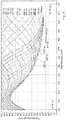
- Fig. 4 illustrates simulation results for transmission curves of the etalon as a function of wavelength and a gap between the reflective surfaces of the etalon.
- a wide tunable spectral filter (Fabry-Perot etalon) is considered providing the transmission curves within the spectral range of 400 nm-700 nm.
- each pixel measures the overall intensity of light rays incident on said pixel at different angles.
- the light passage through the etalon 108 provides that each wavelength component of the input light is differently affected by the transmission profile of the etalon.
- each pixel in the pixel matrix 104 measures the integrated intensity of multiple weighted modified spectra. Accordingly, each frame is acquired with a pre-determined weighted sum of wavelengths.
- the spectral profiles of each two exposures (frames) may significantly overlap.
- the number of the detected spectral bands is equal to the number of exposures.
- the control unit 106 receives the output of the pixel matrix in the form of n image data pieces, I 1 , ...I N , which are indicative of the spectral images detected during the n frames' acquisition with n different transmission profiles of the etalon defined by n different gaps.
- This image data pieces may be stored in the memory 106A.
- the variation of the gap values is managed by the controller 107, and the corresponding transmission profiles of the etalon are thus known.
- the values of gaps and/or corresponding transmission profiles may also be stored in the memory.
- the analyzer 106B utilizes the transmission profiles' data for processing the image data I 1 , ...I N for detecting/reconstructing the spectrum of the object being imaged.
- an error minimization may be applied such as least mean squares.
- the spectral resolution spectral bands
- the spectral resolution may be increased up to the number of exposures.
- the etalon is preferably tunable within a wide spectral range.
- the tuning is achieved by varying the gap between the reflectors S 1 and S 2 .
- Such a wide spectral range tunable etalon may require a high aspect ratio between the width and gap between the reflectors, and also the gap is to be adjustable to be variable to very close proximity between the reflectors (e.g. a few tens of nanometers).
- the gap variation is achieved by associating at least one of the reflectors with MEMS-based actuator(s) operable to controllably move at least one of the reflectors with respect to the other.
- MEMS-based actuator(s) operable to controllably move at least one of the reflectors with respect to the other.
- the present invention provides novel, simple and effective hyperspectral imaging technique enabling reconstruction of the spectrum of an object / scene.
- the invention provides for acquiring a hyperspectral cube with full spatial resolution and spectral resolution, without any preliminary information about the object /scene being imaged.
Description
- The present invention is in the field of imaging techniques, and relates to a method and system for spectral imaging.
- Spectral imaging is aimed at providing at least some spectral information about an object at every location in an image plane. Various spectral imaging techniques have been developed, including multispectral imaging, hyperspectral imaging, full spectral imaging, imaging spectroscopy or chemical imaging. Spectral images are often represented as an image cube, a type of data cube.
- Multispectral (MS) and hyperspectral (HS) cubes could be acquired in many ways. Some systems (utilizing whiskbroom, pushbroom and tunable filters for realizing HS imagers), rely on multiple acquisitions of 1D or 2D subsets of the 3D HS cube followed by simple reconstruction. Some other systems include polychromatic sensors that trade-off resolution with spectral information (similar to the Bayer CFA) and require spatio-spectral reconstruction algorithms [Y. Monno, M. Tanaka and M. Okutomi Proceedings of IS&T/SPIE Electronic Imaging (EI2012), Digital Photography VIII, Vol.8299, pp.82990O-1-7, January, 2012; Y. Murakami, M. Yamaguchi, and N. Ohyama, "Hybrid-resolution multispectral imaging using color filter array," Opt. Express 20, 7173-7183 (2012)]. Further hyperspectral imaging devices are disclosed in utility model
DE29824467U1 and patent application publicationsUS2010/211333A1 andUS2008/144001A1 . - Recently, several HS snapshot acquisition techniques have been developed. Some of them are based on compressed sensing in which the HS image is assumed to be sparse, and an additional optical element is used within the imaging system, to compress the data. Such techniques are described in the following publications: A. Stern, "Compressed imaging system with linear sensors," Opt. Lett. 32, 3077-3079 (2007); A. Wagadarikar, R. John, R. Willett, and D. Brady, "Single disperser design for coded aperture snapshot spectral imaging," Appl. Opt. 47, B44-B51 (2008); C. Li, T. Sun, K. F. Kelly and Y. Zhang. A compressive sensing and unmixing scheme for hyperspectral data processing. IEEE_J_IP 21(3), pp. 1200-1210. 2012; M. A. Golub, M. Nathan, A. Averbuch, E. Lavi, V. A. Zheludev, and A. Schclar, "Spectral multiplexing method for digital snapshot spectral imaging," Appl. Opt. 48, 1520-1526 (2009).
- However, these techniques require prior knowledge of the scene being imaged, and also typically suffer from low light efficiency, and systems implementing such techniques are rather complex.
- As for the integral field spectroscopic systems, the common underlying principle of these systems is similar to light field cameras in the sense that the spectral information is traded-off with spatial resolution. Thus, a number of spectral bands in the detected light is equal to the resolution degradation ratio. Integral field hyperspectral imaging techniques, such as lenslet array, fibre array, image slicer and micro-slicer, all exhibit this behavior. Yet another known solution concerns the use of a 2D grating that diverges incident light according to the grating' diffraction order to form multiple, multispectral sub-images on the sensor; this is followed by reconstruction algorithms. This method allows fast hyperspectral cube acquisition, but the resultant image suffers from low spatial resolution; also the required setup could not be integrated in common cameras.
- The present invention provides a novel technique for hyperspectral imaging that enables to acquire a complete hyperspectral cube of arbitrary scene. The invention provides for acquiring a hyperspectral cube with full spatial resolution and spectral resolution. This technique needs neither any preliminary information of the scene nor additional assumptions.
- A hyperspectral imaging system of the invention includes an etalon with a wide spectral range, e.g. a clear aperture Fabry-Perot etalon with wide transmission peak, placed in front of a pixel matrix of a detector, i.e. upstream of the pixel matrix with respect to the input light propagation direction. The system operates in a "multiple-exposure" mode to acquire multiple frames of the scene, while using multiple different, partially overlapping transmission curves of the etalon. More specifically, the system operates to acquire a set of frames, each with a different transmission function of the etalon, i.e. slightly displaced transmission peak of the etalon. The transmission profiles are wide to capture more light and consequently improve the signal to noise ratio. Thus, each frame is acquired with a pre-determined weighted sum of wavelengths, and the spectral profiles of each two exposures (frames) may significantly overlap. Following the acquisition, spectral reconstruction algorithms are applied to recover the spectrum of the image. In general, the number of spectral bands is equal to the number of exposures.
- Thus, the present invention provides for acquiring a complete hyperspectral cube of arbitrary scene with full spatial and spectral resolutions, while having a simple construction of standard imaging system, additionally equipped with a tunable dispersive element (spectral filter) with broad spectral transmission profiles that allows acquiring within each frame a weighted sum of wavelengths. The hyperspectral imaging system of the invention could be integrated within both color (Bayer) and monochrome image sensors. The clear aperture Fabry-Perot etalon may also be used for standard color imaging, thus enabling a dual-purpose imaging system (standard color + hyperspectral). The system has improved noise performance, since each frame is acquired with reduced noise content.
- The approach of the invention is general and may fit multiple imaging scenarios, including UV/VIS/NIR; and is not sensor dependent. The imaging system of the invention may be integrated in industrial cameras, surveillance cameras, medical devices, quality control equipment, spectrometry systems for inspecting chemical compounds and biological tissues.
- The present invention takes advantage of the hyperspectral imaging technique described in
US patent application No. 62/075,972 - The technique of the present invention provides for effective spectrum reconstruction of very small objects up to single-pixel objects. To this end, the invention utilizes multi-exposure approach with different transmission functions of the wide spectral etalon.
- The tunable etalon is configured for tunability over a relatively wide spectral range, and also preferably with sufficient Free Spectral Range (FSR). Furthermore, in order to enable generation of accurate color images, the etalon is preferably configured with low finesse (namely sufficiently wide spectral transmission peak). This, on the one hand, provides for creating images with accurate (e.g. faithful) colors, and, on the other hand, allows sufficient light to pass to the sensor (pixel matrix).
- The etalon includes a pair of substantially parallel, generally reflective surfaces, spaced from one another by a gap (optical distance). Generally, the transmission function T of such etalon is a function of wavelength λ, transmission of the two surfaces, and the value of gap between these surfaces. For the etalon formed by given reflective surfaces (i.e. given transmission(s) thereof), the etalon's transmission is a function of wavelength and gap, T(λ, gap). Thus, by controllably varying the gap between the reflective surface to provide a sequence of n different gap values during image acquisitions of n frames (n exposures), respectively, different n transmission functions of the etalon are applied to the input light field which differently affect detection of light components of n wavelengths λ1, ...λN by the pixel matrix of the detector. This allows reconstruction of the spectrum of the object by processing the image data of n frames.
- Thus, according to one broad aspect of the invention, there is provided a hyperspectral imaging system for use in reconstructing spectral data of an object, the system being disclosed by
claim 1. - According to another aspect, the invention provides an imaging method for use in reconstructing spectral data of an object as disclosed by
claim 9. - In order to better understand the subject matter that is disclosed herein and to exemplify how it may be carried out in practice, embodiments will now be described, by way of non-limiting examples only, with reference to the accompanying drawings, in which:
-
Fig. 1 is a block diagram of a hyperspectral imaging system of the present invention; -
Fig. 2 more specifically illustrates the light propagation scheme in the system of the invention; -
Fig. 3 schematically illustrates a Fabry-Perot etalon suitable to be used in the system of the present invention; and -
Fig. 4 illustrates simulation results for transmission curves of the etalon as a function of wavelength and a gap between the reflective surfaces of the etalon. - Reference is made to
Fig. 1 illustrating, by way of a block diagram, ahyperspectral imaging system 100 of the invention. Theimaging system 100 includes anoptical unit 102 for locating in front of (upstream of) an imaging plane IP defined by apixel matrix unit 104 of a detector, and acontrol system 105. Thecontrol system 105 includes acontrol unit 106 configured for data communication with a readout circuit of thepixel matrix 104 for receiving image data therefrom and processing the received data. Thecontrol unit 106 may be integral with thepixel matrix unit 104, e.g. may be a software module of the readout circuit of thepixel matrix unit 104. - The
optical unit 102 includes a tunable dispersive unit/element being a widespectral filter 108. For example, a clear aperture Fabry-Perot etalon with wide transmission peak can be used. - The
control unit 106 includes inter alia data input and output utilities (not shown), a memory module 106A, ananalyzer module 106B adapted for analyzing the image data from thepixel matrix unit 104. This will be described more specifically further below. - Also provided in the
control system 105 is acontroller 107, which is configured for controlling the tuning of theetalon 108 and providing data about the variation of the tunable parameter. The controller may be part of thecontrol unit 106, or may be a separate module, or may be part of theetalon 108. The tuning of the etalon is aimed at controllably varying its spectral transmission profile (transmission function), i.e. changing the dispersive pattern of light passing therethrough. In case of the Fabry-Perot type etalon, the tunable parameter of theetalon 108 is a gap between its reflective surfaces. Thecontroller 107 operates the tuning procedure and provides data about the different values of the tunable parameter, e.g. gap1, ...gapN, or provides data about the corresponding transmission functions of the etalon, T1, ...TN. - As exemplified in
Fig. 2 , theetalon 108 is preferably located in front of animaging lens module 109 of the detector being spaced-apart therefrom along an optical axis OA. Thepixel matrix 104 is located in the imaging plane IP which is typically located in a back focal plane of thelens module 109. -
Fig. 3 more specifically exemplifies the configuration ofetalon 108 tunable to provide various spectral transmission curves. Thetunable etalon 108 is preferably sufficiently thin to fit in the optical path of a camera. Thetunable etalon 108 of this example is configured as a clear aperture Fabry-Perot etalon formed by two reflectors (reflective surfaces) S1 and S2. According to the invention, the reflectors S1 and S2 are spaced apart by a gap (etalon-spacing), which is variable/tunable, by moving at least one of the surfaces with respect to the other, to vary the spectral transmission profile of the etalon. As shown in the figure, the inner surfaces of the reflectors S1 and S2 may be provided with coatings C1 and C2 having high refractive index, to thereby provide for relatively wide spectral transmission peak of the etalon, and the outer surface of at least one of the mirrors S1 and S2 may be provided with anti-reflective coating - two such anti-reflective coatings AR1 and AR2 on the mirrors Si and S2 are shown in this example. - At least one of the reflective surfaces Si and S2 of the
etalon 108 is mounted on / associated with actuator(s) providing for controlling the gap between the reflective surfaces. According to the invention, the actuator(s) include MEMS actuator(s), such as electrostatic MEMS actuator(s). The actuator(s) may further include piezoelectric actuator(s). - The
etalon 108 may include electro-optical media placed in the space between the reflective surfaces S1 and S2. Such electro optical media is configured and operable for providing control over the optical distance between the reflective surfaces. - Turning back to
Fig. 1 , theimaging system 100 operates in a multiple-exposure mode, namely acquires a set / sequence of frames, each being a different spectral image of a region of interest (as a result of input light interaction with different dispersive pattern). During each exposure or imaging session (each frame acquisition), the input light field Lin, propagating from the region of interest, passes through theetalon 108 having a certain transmission profile (i.e. spectral position of the transmission peak), defined by a certain value of the gap being different from that of the other exposures / imaging sessions. A resulting spectral image is detected by the pixel matrix. A set of frames is acquired, each with a slightly displaced transmission peak. Thus, during n exposures performed with n different partially overlapping transmission profiles of the etalon, T1, ...TN, achieved by setting n values of the gap, n different spectral images are detected. The transmission profiles are wide to capture more light and consequently improve the signal to noise ratio. -
Fig. 4 illustrates simulation results for transmission curves of the etalon as a function of wavelength and a gap between the reflective surfaces of the etalon. In this simulation, a wide tunable spectral filter (Fabry-Perot etalon) is considered providing the transmission curves within the spectral range of 400 nm-700 nm. - Typically, in an imaging system, each pixel measures the overall intensity of light rays incident on said pixel at different angles. The light passage through the
etalon 108 provides that each wavelength component of the input light is differently affected by the transmission profile of the etalon. Thus, each pixel in thepixel matrix 104 measures the integrated intensity of multiple weighted modified spectra. Accordingly, each frame is acquired with a pre-determined weighted sum of wavelengths. The spectral profiles of each two exposures (frames) may significantly overlap. The number of the detected spectral bands is equal to the number of exposures. - The
control unit 106 receives the output of the pixel matrix in the form of n image data pieces, I1, ...IN, which are indicative of the spectral images detected during the n frames' acquisition with n different transmission profiles of the etalon defined by n different gaps. This image data pieces may be stored in the memory 106A. The variation of the gap values is managed by thecontroller 107, and the corresponding transmission profiles of the etalon are thus known. The values of gaps and/or corresponding transmission profiles may also be stored in the memory. - The
analyzer 106B utilizes the transmission profiles' data for processing the image data I1, ...IN for detecting/reconstructing the spectrum of the object being imaged. The image data can be written as:
- The reflectance vector of the object could thus be reconstructed by:

- In case the number of exposures exceeds the required spectral resolution, an error minimization may be applied such as least mean squares. Alternatively, the spectral resolution (spectral bands) may be increased up to the number of exposures.
- As indicated above, the etalon is preferably tunable within a wide spectral range. The tuning is achieved by varying the gap between the reflectors S1 and S2. Such a wide spectral range tunable etalon may require a high aspect ratio between the width and gap between the reflectors, and also the gap is to be adjustable to be variable to very close proximity between the reflectors (e.g. a few tens of nanometers). Also, as indicated above, the gap variation is achieved by associating at least one of the reflectors with MEMS-based actuator(s) operable to controllably move at least one of the reflectors with respect to the other. An example of a tunable MEMS-based etalon suitable to be used in the imaging system of the present invention is described in
US patent application No. 62/192,658 - Thus, the present invention provides novel, simple and effective hyperspectral imaging technique enabling reconstruction of the spectrum of an object / scene. The invention provides for acquiring a hyperspectral cube with full spatial resolution and spectral resolution, without any preliminary information about the object /scene being imaged.
Claims (11)
- A hyperspectral imaging system for use in reconstructing spectral data of an object, the system comprising:a pixel matrix of a detector configured and operable to perform image acquisition sessions and detect, in each image acquisition session, an image of light originated at an object and generate an image data piece indicative of the detected light;a dispersive unit configured with a wide band spectral transmission profile located in front of the pixel matrix such that, in the image acquisition session, the light propagating to the pixel matrix, interacts with a transmission profile of the dispersive unit during the image acquisition session, and the image data piece corresponds to image acquisition with a pre-determined weighted sum of wavelengths and the detected light at each pixel in the pixel matrix corresponds to the spectral transmission profile of the dispersive unit multiplexed with a spectrum of the object to be determined; anda control system comprising: a controller configured and operable for tuning the dispersive unit during n image acquisition sessions to controllably vary the spectral transmission profile of the dispersive unit by displacing the spectral transmission peak thereof to provide n predetermined different spectral transmission profiles of the dispersive unit which are partially overlapping with one another, such that each image data piece is indicative of a broad-band spectral image detected by the pixel matrix and corresponding to the different spectral transmission profile of the dispersive unit; and a control unit in data communication with the detector and being configured and operable for processing data corresponding to the detected light intensities for n image data pieces generated by the pixel matrix in said n image acquisition sessions, where the detected light at each pixel in the pixel matrix corresponds to the spectral data of the object multiplexed with the spectral transmission profile of the dispersive unit, and utilizing data about the predetermined n spectral transmission profiles, and extracting the reconstructed spectral data of the object;characterized in that the dispersive unit comprises an etalon configured with a wide spectral range;wherein the etalon comprises a pair of substantially parallel, reflective surfaces, spaced from one another by a gap, the transmission profile of the etalon being a function of wavelength, transmission of the two reflective surfaces, and a value of the gap between these surfaces;wherein the controller is configured and operable for operating the dispersive unit by controllably varying the value of the gap between the reflective surfaces to provide a sequence of said n different gap values during the n image acquisition sessions, respectively, such that different n transmission functions of the dispersive unit are applied to the light which differently affect detection of light components of different wavelengths by the pixel matrix of the detector; andwherein at least one of the reflective surfaces is associated with one or more MEMS actuators configured and operable for controlling the gap between the reflective surfaces.
- The imaging system of Claim 1, wherein the transmission profile of the dispersive unit is a function of wavelengths and a tunable parameter of the dispersive unit.
- The imaging system of any one of Claims 1 or 2, wherein the plurality of the image data pieces is a function of the plurality of the transmission profiles of the dispersive unit and the spectrum of the object to be determined.
- The imaging system of Claim 1 or 2, comprising at least one of the following for the controllable variation of the value of the optical gap: one or more piezoelectric actuators; electro-optical media placed in the gap between the reflective surfaces and configured and operable for controlling over the optical distance between the reflective surfaces.
- The imaging system of any one of Claims 1 to 4, wherein the etalon is configured as a clear aperture Fabry-Perot etalon.
- The imaging system of Claim 5, being configured and operable for dual-mode imaging, selectively operating in a standard color imaging mode and a hyperspectral imaging mode.
- The imaging system of any one of the preceding Claims, wherein the detector is configured as a monochromatic or color detector.
- The imaging system of any one of the preceding Claims, wherein the control unit is configured and operable for processing the n image data pieces and determining the reconstructed spectral data of the object, utilizing the following relation between the n image data pieces I1, ...IN and n spectral bands R(λ1) ... R(λN) of the object:

- A hyperspectral imaging method for use in reconstructing spectral data of an object, the method comprising: providing the imaging system of any one of the preceding claims; sequentially acquiring a plurality of n image frames, by performing n imaging sessions of the object onto a pixel matrix of a detector, while sequentially applying to the light being imaged n predetermined wide spectral band dispersion profiles being different from one another in a position of a spectral transmission peak and partially overlapping with one another, thereby obtaining n image data pieces indicative of n different spectral images of the object, each of the image data pieces being a function of the respective dispersion profile and a spectrum of the object to be determined; and processing data corresponding to light intensities detected by a pixel matrix for said n image data pieces, where the detected light at each pixel corresponds to the spectral data of the object multiplexed with the spectral transmission profile of the dispersive unit, and utilizing the data about the predetermined n dispersion profiles, for extracting reconstructed n spectral bands of the object being imaged.
- The method of Claim 9, wherein said applying of the dispersion profile comprises interacting the light with a dispersive pattern.
- The method of Claim 9 or 10, wherein data indicative of the image data pieces is a function of the corresponding dispersive profiles and a spectrum of the object to be determined.
Applications Claiming Priority (2)
| Application Number | Priority Date | Filing Date | Title |
|---|---|---|---|
| US201562198789P | 2015-07-30 | 2015-07-30 | |
| PCT/IL2016/050827 WO2017017684A1 (en) | 2015-07-30 | 2016-07-28 | Spectral imaging method and system |
Publications (3)
| Publication Number | Publication Date |
|---|---|
| EP3329209A1 EP3329209A1 (en) | 2018-06-06 |
| EP3329209A4 EP3329209A4 (en) | 2019-05-01 |
| EP3329209B1 true EP3329209B1 (en) | 2022-11-09 |
Family
ID=57884188
Family Applications (1)
| Application Number | Title | Priority Date | Filing Date |
|---|---|---|---|
| EP16829966.7A Active EP3329209B1 (en) | 2015-07-30 | 2016-07-28 | Spectral imaging method and system |
Country Status (6)
| Country | Link |
|---|---|
| US (1) | US10605660B2 (en) |
| EP (1) | EP3329209B1 (en) |
| KR (1) | KR102049373B1 (en) |
| CN (1) | CN108291800B (en) |
| IL (1) | IL256975B (en) |
| WO (1) | WO2017017684A1 (en) |
Families Citing this family (13)
| Publication number | Priority date | Publication date | Assignee | Title |
|---|---|---|---|---|
| CN109073462B (en) * | 2016-04-21 | 2021-09-24 | 苹果公司 | Multiplexing and encoding for reference switching |
| US10288483B2 (en) * | 2017-04-09 | 2019-05-14 | Cymer, Llc | Recovering spectral shape from spatial output |
| US11092492B2 (en) | 2017-09-20 | 2021-08-17 | Unispectral Ltd. | Projector imaging system with auto-homing tunable filter |
| US11204279B2 (en) | 2017-12-21 | 2021-12-21 | Sony Semiconductor Solutions Corporation | Apparatus and method |
| CN111788462A (en) * | 2018-03-18 | 2020-10-16 | 尤尼斯拜特罗有限责任公司 | Generating narrow-band spectral images from broadband spectral images |
| CN109087262B (en) * | 2018-08-04 | 2022-07-22 | 郑州大学 | Multi-view spectral image reconstruction method and storage medium |
| KR102362278B1 (en) * | 2019-11-08 | 2022-02-11 | 한국과학기술원 | Spectral apparatus incorporating tunable spectral filter with multiple resonances, and method for acquiring spectral information thereof |
| US11418727B2 (en) | 2019-12-27 | 2022-08-16 | Simmonds Precision Products, Inc. | Actuated static masks for coded aperture imaging |
| CN111174912B (en) * | 2020-01-03 | 2021-02-23 | 南京大学 | Snapshot type dispersion ambiguity-resolving hyperspectral imaging method |
| CN113468915A (en) * | 2020-03-31 | 2021-10-01 | 吉林求是光谱数据科技有限公司 | Mobile phone fingerprint identification system and identification method with true and false fingerprint identification function |
| CN111397733B (en) * | 2020-04-23 | 2021-03-02 | 湖南大学 | Single/multi-frame snapshot type spectral imaging method, system and medium |
| CN116249475A (en) * | 2020-07-14 | 2023-06-09 | 澳大利亚眼科研究中心有限公司 | Non-mydriatic hyperspectral eye base camera |
| CN113418873B (en) * | 2021-06-23 | 2022-05-17 | 中国科学院长春光学精密机械与物理研究所 | Hyperspectral imaging system and reconstruction spectral imaging method |
Family Cites Families (38)
| Publication number | Priority date | Publication date | Assignee | Title |
|---|---|---|---|---|
| US583420A (en) * | 1897-05-25 | Half to rodolphtjs c | ||
| US5583936A (en) | 1993-05-17 | 1996-12-10 | Macrovision Corporation | Video copy protection process enhancement to introduce horizontal and vertical picture distortions |
| GB9411561D0 (en) * | 1994-06-07 | 1994-08-03 | Richmond Holographic Res | Stereoscopic display |
| US5834203A (en) | 1997-08-25 | 1998-11-10 | Applied Spectral Imaging | Method for classification of pixels into groups according to their spectra using a plurality of wide band filters and hardwire therefore |
| US6587484B1 (en) * | 2000-10-10 | 2003-07-01 | Spectrasensor, Inc,. | Method and apparatus for determining transmission wavelengths for lasers in a dense wavelength division multiplexer |
| WO2002088646A1 (en) | 2001-05-02 | 2002-11-07 | Csir | Spectrometric using broadand filters with overlapping spectral ranges |
| US8174694B2 (en) * | 2001-12-21 | 2012-05-08 | Bodkin Design And Engineering Llc | Hyperspectral imaging systems |
| US6900431B2 (en) * | 2003-03-21 | 2005-05-31 | Predicant Biosciences, Inc. | Multiplexed orthogonal time-of-flight mass spectrometer |
| CN1225824C (en) * | 2003-07-11 | 2005-11-02 | 清华大学 | Composite external chamber stepping toning semiconductor laser and its toning method |
| WO2005008200A2 (en) | 2003-07-18 | 2005-01-27 | Chemimage Corporation | Method and apparatus for compact dispersive imaging spectrometer |
| JP2005055670A (en) | 2003-08-04 | 2005-03-03 | Seiko Epson Corp | Mems device, method of manufacturing the same, and mems module |
| US7177505B2 (en) | 2004-03-04 | 2007-02-13 | Rosemount Inc. | MEMS-based actuator devices using electrets |
| US7554667B1 (en) | 2005-08-25 | 2009-06-30 | Ball Aerospace & Technologies Corp. | Method and apparatus for characterizing hyperspectral instruments |
| US7342658B2 (en) * | 2005-12-28 | 2008-03-11 | Eastman Kodak Company | Programmable spectral imaging system |
| US20080144001A1 (en) * | 2006-12-15 | 2008-06-19 | Bauke Heeg | Spectral imaging device |
| JP2008182103A (en) | 2007-01-25 | 2008-08-07 | Olympus Corp | Airtight seal package |
| JP2008256837A (en) | 2007-04-03 | 2008-10-23 | Yamaichi Electronics Co Ltd | Fabry-perot tunable filter and method of manufacturing the same |
| CN201035181Y (en) * | 2007-04-11 | 2008-03-12 | 福州高意通讯有限公司 | A F-P etalon type wavestrip switch |
| US8537354B2 (en) * | 2007-07-31 | 2013-09-17 | ChemImage Technologies, LLC | System and method for instrument response correction based on independent measurement of the sample |
| US8305575B1 (en) * | 2008-06-23 | 2012-11-06 | Spectral Sciences, Inc. | Adaptive spectral sensor and methods using same |
| US20100211333A1 (en) * | 2009-01-14 | 2010-08-19 | Integrated Process Resources, Inc. | Leak Detection and Identification System |
| EP2284624B1 (en) | 2009-07-29 | 2020-02-26 | Ricoh Company, Ltd. | Fixing Device and Image Forming Apparatus Incorporating Same |
| IL201742A0 (en) * | 2009-10-25 | 2010-06-16 | Elbit Sys Electro Optics Elop | Tunable spectral filter |
| US8384905B2 (en) | 2009-11-10 | 2013-02-26 | Corning Incorporated | Tunable light source for label-independent optical reader |
| CN101923047A (en) * | 2010-05-17 | 2010-12-22 | 南通北极光自动控制技术有限公司 | Spectrum analyzer for near-infrared-on-line detecting diffuse reflection |
| CN101975610B (en) * | 2010-09-03 | 2012-02-15 | 北京理工大学 | Light path structure of scanning and imaging spectrometer |
| CN102053361A (en) | 2010-11-24 | 2011-05-11 | 福州高意通讯有限公司 | Adjustable etalon |
| CN103048781A (en) | 2011-10-11 | 2013-04-17 | 福州高意通讯有限公司 | MEMS (Micro-Electro Mechanical System) adjustable etalon |
| CN102393248B (en) * | 2011-10-26 | 2013-09-11 | 中国科学院空间科学与应用研究中心 | Time-resolved extreme-low-light multispectral imaging system and method |
| US9599508B2 (en) * | 2012-05-18 | 2017-03-21 | Rebellion Photonics, Inc. | Divided-aperture infra-red spectral imaging system |
| CN102798987B (en) * | 2012-07-30 | 2015-01-21 | 天津奇谱光电技术有限公司 | Tunable optical filter with fixed frequency space and single-mode output |
| CN103257404B (en) * | 2013-06-04 | 2016-01-13 | 贵阳恒浩光电科技有限公司 | A kind of MEMS Fabry-Perot cavity tunable filter |
| CN103325096B (en) * | 2013-06-25 | 2016-04-13 | 中国科学院遥感与数字地球研究所 | Based on the wide cut high spectrum image reconstructing method that many/high spectrum image merges |
| CN106133563B (en) | 2013-11-26 | 2019-11-19 | 英菲尼斯有限责任公司 | The MEMS- fabry-perot filter of tunable wave length |
| CN103808410B (en) * | 2014-02-21 | 2016-02-24 | 清华大学 | The device of antithesis compression coding high light spectrum image-forming |
| FR3021127B1 (en) * | 2014-05-19 | 2017-10-13 | Commissariat Energie Atomique | SYSTEM AND METHOD FOR ACQUIRING HYPERSPECTRAL IMAGES |
| WO2016071909A1 (en) | 2014-11-06 | 2016-05-12 | Ramot At Tel-Aviv University Ltd. | Spectral imaging method and system |
| EP3323011B1 (en) | 2015-07-15 | 2024-03-27 | Technology Innovation Momentum Fund (Israel) Limited Partnership | Tunable mems etalon |
-
2016
- 2016-07-28 EP EP16829966.7A patent/EP3329209B1/en active Active
- 2016-07-28 US US15/746,824 patent/US10605660B2/en active Active
- 2016-07-28 CN CN201680043412.0A patent/CN108291800B/en active Active
- 2016-07-28 KR KR1020187003746A patent/KR102049373B1/en active IP Right Grant
- 2016-07-28 WO PCT/IL2016/050827 patent/WO2017017684A1/en active Application Filing
-
2018
- 2018-01-17 IL IL256975A patent/IL256975B/en unknown
Also Published As
| Publication number | Publication date |
|---|---|
| US10605660B2 (en) | 2020-03-31 |
| EP3329209A4 (en) | 2019-05-01 |
| KR102049373B1 (en) | 2019-11-27 |
| IL256975A (en) | 2018-03-29 |
| WO2017017684A1 (en) | 2017-02-02 |
| CN108291800B (en) | 2021-07-13 |
| IL256975B (en) | 2022-06-01 |
| KR20180030995A (en) | 2018-03-27 |
| CN108291800A (en) | 2018-07-17 |
| EP3329209A1 (en) | 2018-06-06 |
| US20180209850A1 (en) | 2018-07-26 |
Similar Documents
| Publication | Publication Date | Title |
|---|---|---|
| EP3329209B1 (en) | Spectral imaging method and system | |
| Cao et al. | Computational snapshot multispectral cameras: Toward dynamic capture of the spectral world | |
| EP3830551B1 (en) | A hybrid spectral imager | |
| US10101206B2 (en) | Spectral imaging method and system | |
| US10274420B2 (en) | Compact multifunctional system for imaging spectroscopy | |
| CN106456070B (en) | Image forming apparatus and method | |
| Wagadarikar et al. | Spectral image estimation for coded aperture snapshot spectral imagers | |
| US9426401B2 (en) | Mechanisms for obtaining information from a scene | |
| US9253420B2 (en) | Hyperspectral single pixel imager with fabry perot filter | |
| Oiknine et al. | NIR hyperspectral compressive imager based on a modified Fabry–Perot resonator | |
| Koten et al. | Automatic video system for continues monitoring of the meteor activity | |
| Liu et al. | Measurement dimensions compressed spectral imaging with a single point detector | |
| Jeon et al. | Multisampling compressive video spectroscopy | |
| US10395134B2 (en) | Extraction of spectral information | |
| KR102362278B1 (en) | Spectral apparatus incorporating tunable spectral filter with multiple resonances, and method for acquiring spectral information thereof | |
| Shepherd et al. | Adaptive MWIR spectral imaging sensor | |
| Muise et al. | Recent results of integrated sensing and processing using a programmable hyperspectral imaging sensor | |
| Rueda et al. | Experimental demonstration of a colored coded aperture-based compressive spectral imaging system | |
| US20220341781A1 (en) | Optical device and method | |
| WO2008124446A1 (en) | Dynamic spectral imaging device with spectral zooming capability | |
| Muise et al. | Recent results of integrated sensing and processing with hyperspectral imager | |
| Howard | Fourier Multispectral Imaging in the Shortwave Infrared | |
| Ygouf et al. | Data Post Processing and Algorithm Development for the WFIRST-AFTA Coronagraph: First Progress Report | |
| Plemmons et al. | Deblurring Compressive Spectro-Polarimetric Images Taken Trough Atmospheric Turbulence |
Legal Events
| Date | Code | Title | Description |
|---|---|---|---|
| STAA | Information on the status of an ep patent application or granted ep patent |
Free format text: STATUS: THE INTERNATIONAL PUBLICATION HAS BEEN MADE |
|
| PUAI | Public reference made under article 153(3) epc to a published international application that has entered the european phase |
Free format text: ORIGINAL CODE: 0009012 |
|
| STAA | Information on the status of an ep patent application or granted ep patent |
Free format text: STATUS: REQUEST FOR EXAMINATION WAS MADE |
|
| 17P | Request for examination filed |
Effective date: 20180116 |
|
| AK | Designated contracting states |
Kind code of ref document: A1 Designated state(s): AL AT BE BG CH CY CZ DE DK EE ES FI FR GB GR HR HU IE IS IT LI LT LU LV MC MK MT NL NO PL PT RO RS SE SI SK SM TR |
|
| AX | Request for extension of the european patent |
Extension state: BA ME |
|
| DAV | Request for validation of the european patent (deleted) | ||
| DAX | Request for extension of the european patent (deleted) | ||
| A4 | Supplementary search report drawn up and despatched |
Effective date: 20190329 |
|
| RIC1 | Information provided on ipc code assigned before grant |
Ipc: G01J 3/28 20060101AFI20190325BHEP Ipc: G01J 3/45 20060101ALI20190325BHEP Ipc: G01J 3/26 20060101ALI20190325BHEP Ipc: G01B 9/02 20060101ALI20190325BHEP Ipc: G01J 3/12 20060101ALI20190325BHEP |
|
| RIN1 | Information on inventor provided before grant (corrected) |
Inventor name: MENDLOVIC, DAVID Inventor name: RAZ, ARIEL |
|
| REG | Reference to a national code |
Ref country code: DE Ref legal event code: R079 Ref document number: 602016076260 Country of ref document: DE Free format text: PREVIOUS MAIN CLASS: G01B0009020000 Ipc: G01J0003280000 |
|
| GRAP | Despatch of communication of intention to grant a patent |
Free format text: ORIGINAL CODE: EPIDOSNIGR1 |
|
| STAA | Information on the status of an ep patent application or granted ep patent |
Free format text: STATUS: GRANT OF PATENT IS INTENDED |
|
| RIC1 | Information provided on ipc code assigned before grant |
Ipc: G01B 9/02 20060101ALI20220519BHEP Ipc: G16H 40/63 20180101ALI20220519BHEP Ipc: G16H 30/20 20180101ALI20220519BHEP Ipc: G01J 3/12 20060101ALI20220519BHEP Ipc: G01J 3/45 20060101ALI20220519BHEP Ipc: G01J 3/26 20060101ALI20220519BHEP Ipc: G01J 3/28 20060101AFI20220519BHEP |
|
| INTG | Intention to grant announced |
Effective date: 20220608 |
|
| GRAS | Grant fee paid |
Free format text: ORIGINAL CODE: EPIDOSNIGR3 |
|
| GRAA | (expected) grant |
Free format text: ORIGINAL CODE: 0009210 |
|
| STAA | Information on the status of an ep patent application or granted ep patent |
Free format text: STATUS: THE PATENT HAS BEEN GRANTED |
|
| AK | Designated contracting states |
Kind code of ref document: B1 Designated state(s): AL AT BE BG CH CY CZ DE DK EE ES FI FR GB GR HR HU IE IS IT LI LT LU LV MC MK MT NL NO PL PT RO RS SE SI SK SM TR |
|
| REG | Reference to a national code |
Ref country code: GB Ref legal event code: FG4D |
|
| REG | Reference to a national code |
Ref country code: CH Ref legal event code: EP Ref country code: AT Ref legal event code: REF Ref document number: 1530666 Country of ref document: AT Kind code of ref document: T Effective date: 20221115 |
|
| REG | Reference to a national code |
Ref country code: DE Ref legal event code: R096 Ref document number: 602016076260 Country of ref document: DE |
|
| REG | Reference to a national code |
Ref country code: IE Ref legal event code: FG4D |
|
| REG | Reference to a national code |
Ref country code: LT Ref legal event code: MG9D |
|
| REG | Reference to a national code |
Ref country code: NL Ref legal event code: MP Effective date: 20221109 |
|
| REG | Reference to a national code |
Ref country code: AT Ref legal event code: MK05 Ref document number: 1530666 Country of ref document: AT Kind code of ref document: T Effective date: 20221109 |
|
| PG25 | Lapsed in a contracting state [announced via postgrant information from national office to epo] |
Ref country code: SE Free format text: LAPSE BECAUSE OF FAILURE TO SUBMIT A TRANSLATION OF THE DESCRIPTION OR TO PAY THE FEE WITHIN THE PRESCRIBED TIME-LIMIT Effective date: 20221109 Ref country code: PT Free format text: LAPSE BECAUSE OF FAILURE TO SUBMIT A TRANSLATION OF THE DESCRIPTION OR TO PAY THE FEE WITHIN THE PRESCRIBED TIME-LIMIT Effective date: 20230309 Ref country code: NO Free format text: LAPSE BECAUSE OF FAILURE TO SUBMIT A TRANSLATION OF THE DESCRIPTION OR TO PAY THE FEE WITHIN THE PRESCRIBED TIME-LIMIT Effective date: 20230209 Ref country code: LT Free format text: LAPSE BECAUSE OF FAILURE TO SUBMIT A TRANSLATION OF THE DESCRIPTION OR TO PAY THE FEE WITHIN THE PRESCRIBED TIME-LIMIT Effective date: 20221109 Ref country code: FI Free format text: LAPSE BECAUSE OF FAILURE TO SUBMIT A TRANSLATION OF THE DESCRIPTION OR TO PAY THE FEE WITHIN THE PRESCRIBED TIME-LIMIT Effective date: 20221109 Ref country code: ES Free format text: LAPSE BECAUSE OF FAILURE TO SUBMIT A TRANSLATION OF THE DESCRIPTION OR TO PAY THE FEE WITHIN THE PRESCRIBED TIME-LIMIT Effective date: 20221109 Ref country code: AT Free format text: LAPSE BECAUSE OF FAILURE TO SUBMIT A TRANSLATION OF THE DESCRIPTION OR TO PAY THE FEE WITHIN THE PRESCRIBED TIME-LIMIT Effective date: 20221109 |
|
| PG25 | Lapsed in a contracting state [announced via postgrant information from national office to epo] |
Ref country code: RS Free format text: LAPSE BECAUSE OF FAILURE TO SUBMIT A TRANSLATION OF THE DESCRIPTION OR TO PAY THE FEE WITHIN THE PRESCRIBED TIME-LIMIT Effective date: 20221109 Ref country code: PL Free format text: LAPSE BECAUSE OF FAILURE TO SUBMIT A TRANSLATION OF THE DESCRIPTION OR TO PAY THE FEE WITHIN THE PRESCRIBED TIME-LIMIT Effective date: 20221109 Ref country code: LV Free format text: LAPSE BECAUSE OF FAILURE TO SUBMIT A TRANSLATION OF THE DESCRIPTION OR TO PAY THE FEE WITHIN THE PRESCRIBED TIME-LIMIT Effective date: 20221109 Ref country code: IS Free format text: LAPSE BECAUSE OF FAILURE TO SUBMIT A TRANSLATION OF THE DESCRIPTION OR TO PAY THE FEE WITHIN THE PRESCRIBED TIME-LIMIT Effective date: 20230309 Ref country code: HR Free format text: LAPSE BECAUSE OF FAILURE TO SUBMIT A TRANSLATION OF THE DESCRIPTION OR TO PAY THE FEE WITHIN THE PRESCRIBED TIME-LIMIT Effective date: 20221109 Ref country code: GR Free format text: LAPSE BECAUSE OF FAILURE TO SUBMIT A TRANSLATION OF THE DESCRIPTION OR TO PAY THE FEE WITHIN THE PRESCRIBED TIME-LIMIT Effective date: 20230210 |
|
| PG25 | Lapsed in a contracting state [announced via postgrant information from national office to epo] |
Ref country code: NL Free format text: LAPSE BECAUSE OF FAILURE TO SUBMIT A TRANSLATION OF THE DESCRIPTION OR TO PAY THE FEE WITHIN THE PRESCRIBED TIME-LIMIT Effective date: 20221109 |
|
| PG25 | Lapsed in a contracting state [announced via postgrant information from national office to epo] |
Ref country code: SM Free format text: LAPSE BECAUSE OF FAILURE TO SUBMIT A TRANSLATION OF THE DESCRIPTION OR TO PAY THE FEE WITHIN THE PRESCRIBED TIME-LIMIT Effective date: 20221109 Ref country code: RO Free format text: LAPSE BECAUSE OF FAILURE TO SUBMIT A TRANSLATION OF THE DESCRIPTION OR TO PAY THE FEE WITHIN THE PRESCRIBED TIME-LIMIT Effective date: 20221109 Ref country code: EE Free format text: LAPSE BECAUSE OF FAILURE TO SUBMIT A TRANSLATION OF THE DESCRIPTION OR TO PAY THE FEE WITHIN THE PRESCRIBED TIME-LIMIT Effective date: 20221109 Ref country code: DK Free format text: LAPSE BECAUSE OF FAILURE TO SUBMIT A TRANSLATION OF THE DESCRIPTION OR TO PAY THE FEE WITHIN THE PRESCRIBED TIME-LIMIT Effective date: 20221109 Ref country code: CZ Free format text: LAPSE BECAUSE OF FAILURE TO SUBMIT A TRANSLATION OF THE DESCRIPTION OR TO PAY THE FEE WITHIN THE PRESCRIBED TIME-LIMIT Effective date: 20221109 |
|
| REG | Reference to a national code |
Ref country code: DE Ref legal event code: R097 Ref document number: 602016076260 Country of ref document: DE |
|
| PG25 | Lapsed in a contracting state [announced via postgrant information from national office to epo] |
Ref country code: SK Free format text: LAPSE BECAUSE OF FAILURE TO SUBMIT A TRANSLATION OF THE DESCRIPTION OR TO PAY THE FEE WITHIN THE PRESCRIBED TIME-LIMIT Effective date: 20221109 Ref country code: AL Free format text: LAPSE BECAUSE OF FAILURE TO SUBMIT A TRANSLATION OF THE DESCRIPTION OR TO PAY THE FEE WITHIN THE PRESCRIBED TIME-LIMIT Effective date: 20221109 |
|
| PLBE | No opposition filed within time limit |
Free format text: ORIGINAL CODE: 0009261 |
|
| STAA | Information on the status of an ep patent application or granted ep patent |
Free format text: STATUS: NO OPPOSITION FILED WITHIN TIME LIMIT |
|
| 26N | No opposition filed |
Effective date: 20230810 |
|
| PG25 | Lapsed in a contracting state [announced via postgrant information from national office to epo] |
Ref country code: SI Free format text: LAPSE BECAUSE OF FAILURE TO SUBMIT A TRANSLATION OF THE DESCRIPTION OR TO PAY THE FEE WITHIN THE PRESCRIBED TIME-LIMIT Effective date: 20221109 |
|
| PGFP | Annual fee paid to national office [announced via postgrant information from national office to epo] |
Ref country code: DE Payment date: 20230726 Year of fee payment: 8 |
|
| PG25 | Lapsed in a contracting state [announced via postgrant information from national office to epo] |
Ref country code: MC Free format text: LAPSE BECAUSE OF FAILURE TO SUBMIT A TRANSLATION OF THE DESCRIPTION OR TO PAY THE FEE WITHIN THE PRESCRIBED TIME-LIMIT Effective date: 20221109 |
|
| PG25 | Lapsed in a contracting state [announced via postgrant information from national office to epo] |
Ref country code: MC Free format text: LAPSE BECAUSE OF FAILURE TO SUBMIT A TRANSLATION OF THE DESCRIPTION OR TO PAY THE FEE WITHIN THE PRESCRIBED TIME-LIMIT Effective date: 20221109 |
|
| REG | Reference to a national code |
Ref country code: CH Ref legal event code: PL |
|
| PG25 | Lapsed in a contracting state [announced via postgrant information from national office to epo] |
Ref country code: LU Free format text: LAPSE BECAUSE OF NON-PAYMENT OF DUE FEES Effective date: 20230728 |
|
| GBPC | Gb: european patent ceased through non-payment of renewal fee |
Effective date: 20230728 |
|
| PG25 | Lapsed in a contracting state [announced via postgrant information from national office to epo] |
Ref country code: LU Free format text: LAPSE BECAUSE OF NON-PAYMENT OF DUE FEES Effective date: 20230728 |