EP3329098B1 - Anchoring device and method - Google Patents
Anchoring device and method Download PDFInfo
- Publication number
- EP3329098B1 EP3329098B1 EP16747585.4A EP16747585A EP3329098B1 EP 3329098 B1 EP3329098 B1 EP 3329098B1 EP 16747585 A EP16747585 A EP 16747585A EP 3329098 B1 EP3329098 B1 EP 3329098B1
- Authority
- EP
- European Patent Office
- Prior art keywords
- anchoring
- anchoring sleeve
- drilling
- sleeve
- hole
- Prior art date
- Legal status (The legal status is an assumption and is not a legal conclusion. Google has not performed a legal analysis and makes no representation as to the accuracy of the status listed.)
- Active
Links
Images


Classifications
-
- E—FIXED CONSTRUCTIONS
- E21—EARTH OR ROCK DRILLING; MINING
- E21D—SHAFTS; TUNNELS; GALLERIES; LARGE UNDERGROUND CHAMBERS
- E21D21/00—Anchoring-bolts for roof, floor in galleries or longwall working, or shaft-lining protection
- E21D21/0026—Anchoring-bolts for roof, floor in galleries or longwall working, or shaft-lining protection characterised by constructional features of the bolts
- E21D21/0033—Anchoring-bolts for roof, floor in galleries or longwall working, or shaft-lining protection characterised by constructional features of the bolts having a jacket or outer tube
-
- E—FIXED CONSTRUCTIONS
- E21—EARTH OR ROCK DRILLING; MINING
- E21D—SHAFTS; TUNNELS; GALLERIES; LARGE UNDERGROUND CHAMBERS
- E21D20/00—Setting anchoring-bolts
-
- E—FIXED CONSTRUCTIONS
- E21—EARTH OR ROCK DRILLING; MINING
- E21D—SHAFTS; TUNNELS; GALLERIES; LARGE UNDERGROUND CHAMBERS
- E21D21/00—Anchoring-bolts for roof, floor in galleries or longwall working, or shaft-lining protection
- E21D21/0026—Anchoring-bolts for roof, floor in galleries or longwall working, or shaft-lining protection characterised by constructional features of the bolts
- E21D21/0053—Anchoring-bolts in the form of lost drilling rods
-
- E—FIXED CONSTRUCTIONS
- E21—EARTH OR ROCK DRILLING; MINING
- E21D—SHAFTS; TUNNELS; GALLERIES; LARGE UNDERGROUND CHAMBERS
- E21D21/00—Anchoring-bolts for roof, floor in galleries or longwall working, or shaft-lining protection
- E21D21/008—Anchoring or tensioning means
Definitions
- This invention relates to anchoring devices and methods. More specifically, although not exclusively, this invention relates to anchoring devices in the form of rock bolts and to methods of installing such anchoring devices, particularly in subsea environments.
- Rock bolt anchoring devices are known, particularly in mining applications. There are a variety of rock bolt designs available in various materials to suit the application. Rock bolts are generally in the form of an elongate shaft anchored into a borehole formed in rock to provide a reinforcement support thereto.
- US 2004/084217 A1 discloses a method and a device for the drilling of a hole in earth or rock and for securing an anchorage in said hole.
- an anchoring device for securement to strata, according to claim 1.
- the invention provides an anchoring device that is useful as a self-drilling anchor which engages strata surrounding the hole as it is drilled, thereby reducing the steps necessary to secure it in place.
- the anchoring device may comprise a resilient biasing means, which may be for biasing or configured to bias the anchoring sleeve into engagement with surrounding strata, for example when it is in the inserted position.
- the resilient biasing means may comprise or be provided by one or more characteristics of one of the aforementioned components, for example the material and/or shape or configuration of the anchoring sleeve, and/or a separate component, for example a resilient element.
- the drilling head may configured to drill a hole that is smaller than the outer dimension of the anchoring sleeve, for example such that the anchoring sleeve is in interference fit with the hole.
- the drilling head may comprise an outer dimension, for example a maximal outer dimension, that is less or smaller than an outer dimension of the anchoring sleeve, for example an outer dimension or maximal outer dimension of a portion of the sleeve to be inserted into the hole.
- the outer dimension comprises a radial outer dimension, for example an outer diameter.
- the anchoring sleeve may be formed of a material that is elastically deformable, e.g. so as to bias, in use, resiliently the anchoring sleeve against the surrounding strata.
- the elastically deformable material of the anchoring sleeve may comprise or provide at least part of the aforementioned resilient biasing means.
- the anchoring sleeve may comprise gripping means, which may be on its outer surface and/or which may be for engaging or configured to engage the surrounding strata.
- the gripping means may comprise one or more, e.g. two or more such as a plurality of, barbs, hooks or ridges. At least one or each barb, hook or ridge may extend outwardly with respect to the anchoring sleeve. Additionally or alternatively, at least one or each barb, hook or ridge may extend toward the driving end of the rod.
- At least one or each barb, hook or ridge may include a lead-in or taper on a drilling end facing side thereof, for example to facilitate insertion of the anchoring sleeve into the hole, and/or a sharp edge on a driving end facing side thereof, e.g. to engage surrounding strata and/or inhibit removal of the anchoring sleeve from the hole.
- At least one or each barb, hook or ridge may extend about at least a portion of the periphery or circumference of the anchoring sleeve.
- the anchoring sleeve includes a plurality of barbs, hooks or ridges spaced longitudinally and/or along its length.
- the anchoring sleeve may comprise a plurality of barbs, hooks or ridges spaced circumferentially and/or about its periphery.
- at least one or each barb, hook or ridge is integral with the anchoring sleeve, for example a body of the anchoring sleeve.
- the anchoring sleeve may comprise a circumferential discontinuity or slot, which may be longitudinal slot and/or may be or extend along at least a portion, e.g. some or all, of its length.
- the anchoring sleeve may comprise a split sleeve or collet.
- the circumferential discontinuity or slot may enable or permit or allow the anchoring sleeve to be compressed, for example compressed diametrically and/or to a reduced dimension or diameter or effective dimension or diameter.
- the circumferential discontinuity or slot may enable or permit or allow the hole to compress or reduce, in use, the or an outer or effective dimension or diameter of the anchoring sleeve, for example as it is forced therein, e.g. to the inserted position.
- the anchoring sleeve may comprise one or more recesses or depressions or grooves therein, which may extend radially and/or circumferentially and/or longitudinally of the anchoring sleeve.
- the anchoring sleeve comprises one or more stress relief features, e.g. for reducing or configured to reduce, in use, stress, which may be the peak stress, experienced by the anchoring sleeve.
- the aforementioned recesses or depressions or grooves may comprise or provide the stress relief features.
- the or each stress relief feature comprises a groove, e.g. a longitudinal groove, which groove may extend along at least a portion of the length of the anchoring sleeve.
- the anchoring sleeve may comprise a driving surface, for example against which a driving collar of the drilling apparatus may engage, in use, e.g. to force the anchoring sleeve into the hole.
- the anchoring sleeve may comprise a flange, which may be adjacent the driving end of the drilling rod and/or which may comprise or provide the driving surface.
- the anchoring sleeve comprises a flange against which a driving collar of the drilling apparatus may engage, in use, e.g. to force the anchoring sleeve into the hole.
- the anchoring sleeve may comprise a lead-in and/or taper, e.g. to facilitate resilient diametric compression of the anchoring sleeve.
- the lead-in and/or taper may be located adjacent the drilling end of the drilling rod and/or at the opposite end of the anchoring sleeve to the flange.
- the anchoring device may comprise a resilient element, which may at least partially surround the anchoring sleeve.
- the resilient element may comprise or provide at least part of the aforementioned resilient biasing means.
- the resilient element may be configured to be compressed, in use, when the anchoring sleeve is in the inserted position. Additionally or alternatively, the resilient element may be configured to be compressed, in use, between the flange and the strata, for example thereby to urge the anchoring sleeve along a direction that is opposite to the drilling direction.
- the resilient element may comprises a resilient washer, for example a washer formed of a flexible material and/or may be planar or nonplanar in shape. The washer may be undulating and/or may comprise a circumferential discontinuity or split or slot.
- the resilient element may comprise a spring washer.
- the drilling head or an outer dimension thereof may be larger than the internal dimension of the sleeve and/or smaller than the outer dimension of the sleeve, e.g. an outer dimension of the portion of the sleeve to be inserted in the hole.
- the drilling rod may comprise an elongate body or shaft, which may have an outer dimension or diameter that is smaller than the internal dimension of the sleeve and/or may be received therein.
- the drilling head may comprise a different, e.g. harder, material than one or more other parts, e.g. the body or shaft, of the drilling rod.
- the drilling head may be removable from one or more other parts, e.g. the body, such as by a screw thread.
- the body or shaft may comprise a receptacle or blind hole, for example a screw threaded receptacle or blind hole.
- the drilling head may comprise a shaft, for example a screw threaded shaft, which may be threadedly engaged within the receptacle or blind hole.
- the drilling rod or the body or shaft thereof may comprise a scroll or helical formation, e.g. projection, protrusion, flute or groove, which may extend between the drilling head and the driving end.
- the scroll or helical formation may be for conveying or configured to convey spoil or waste therealong, for example from the drilling end toward or to the driving end and/or between the drilling rod and/or scroll or helical formation and the anchoring sleeve.
- an anchoring system for example a rock strata anchoring system, which may comprise one or more anchoring devices, which may comprise one or more features described above, and/or a drilling apparatus, which may comprise one or more features described above.
- the drilling apparatus comprises a connection means, for example a chuck, configured to couple to the driving end of the drilling rod. More preferably, the drilling apparatus comprises a driving collar for engaging the driving surface or flange of the anchoring sleeve, e.g. to force the anchoring sleeve into the hole.
- the drilling apparatus may comprise a motor, e.g. for driving rotation of the drilling rod, and/or a frame with respect to which the chuck is movable, in use, toward and/or away from the strata.
- kits of parts for assembly into an anchoring device e.g. as described above, the kit comprising one or more of the drilling rod and/or the anchoring sleeve and/or the resilient element.
- the kit comprises an anchoring sleeve and a drilling rod for insertion into the anchoring sleeve such that the anchoring sleeve at least partially surrounds the drilling rod, the drilling rod comprising a driving end for coupling to a drilling apparatus and a drilling end with a drilling head for drilling a hole in strata, wherein the device, when assembled, is configured to be coupled with and driven by a drilling apparatus to cause the drilling head to drill a hole into strata and to force, as the hole is drilled, the anchoring sleeve into the hole to an inserted position in which the anchoring sleeve engages the surrounding strata.
- Another aspect of the invention provides method of securing an anchoring device according to claim 11.
- the anchoring sleeve may be urged into engagement with the surrounding strata, for example by a resilient biasing means, e.g. when the anchoring sleeve is in the inserted position.
- the hole that is drilled may be smaller than the outer dimension of the anchoring sleeve, for example such that the anchoring sleeve is forced into an interference fit with the hole.
- the anchoring sleeve may be formed of a material that is elastically deformable, for example so as to bias, e.g. resiliently, the anchoring sleeve against the surrounding strata.
- the anchoring sleeve may comprise gripping means on its the outer surface, which may be urged into engagement with the surrounding strata, for example as the anchoring sleeve is forced into the hole and/or when the anchoring sleeve is in the inserted position.
- the anchoring sleeve may be forced into the hole by a collar of the drilling apparatus, which may engage a driving surface or flange of the anchoring sleeve, which may be adjacent the driving end of the drilling rod.
- the method may comprise engaging the driving surface or the flange by or with or using the collar, e.g. to force the anchoring sleeve into the hole.
- the method may comprise compressing a resilient element, which may at least partially surround the anchoring sleeve, between the flange and the strata, for example as the anchoring sleeve is forced into the inserted position.
- the method may comprise retracting the collar of the drilling apparatus, for example out of engagement with the flange, after the anchoring sleeve is forced into the inserted position, e.g. such that the resilient element urges the anchoring sleeve along a direction that is parallel and/or opposite to the drilling direction. Additionally or alternatively, the method may comprise releasing the drilling rod, for example after the hole is drilled and/or after the anchoring sleeve is forced into the inserted position, e.g. such that the rod remains in the hole.
- the anchoring sleeve may be configured to retain the drilling rod in the hole, for example the anchoring sleeve may prevent or inhibit removal of the drilling rod from the hole.
- the anchoring device may comprise any one or more features of the anchoring system or kit of parts or vice versa.
- the method may comprise any one or more features or steps relevant to one or more features described above in relation to the anchoring system or kit of parts or vice versa.
- the device or system or kit of parts may comprise a bearing plate.
- bearing plate may be configured to be placed on or against the strata, e.g. rock strata, for example against or adjacent an exposed surface of the strata.
- the bearing plate may be substantially flat and may include an aperture through its thickness and/or may be secured, for example affixed, to or on the strata, thereby providing a substantially flat surface thereon.
- the resilient element may be configured to be compressed between the anchoring sleeve or flange thereof and the bearing plate.
- Another aspect of the disclosure provides a computer program element comprising and/or describing and/or defining a three-dimensional design for use with a three-dimensional printing means or printer or additive manufacturing means or device, the three-dimensional design comprising one or more components of an embodiment of the anchoring device described above.
- an anchoring device or anchor 1 engaging a bearing plate BP on a substrate S.
- the anchoring device 1 includes a drill rod 2, an anchor sleeve 3 and a washer (resilient element) 4.
- the anchoring device 1 is shown installed in a subsea seabed substrate S composed of stratified rock to provide a location for a tether (not shown) for restraining subsea pipelines.
- the anchoring device 1 may find other alternative uses, for example to maintain the integrity of a rock wall.
- the drill rod 2 is an elongate member formed from steel, most preferably super duplex steel, and having a first, driving end 20 and a second, drilling end 21 connected by a shaft 22.
- the outer surface 23 of the shaft 22 includes a continuous helical groove 24, for the transport of spoil, and extends from the drilling end 21 to the driving end 20.
- the driving end 20 includes a connection pin 25 configured for releasable connection with a drilling apparatus (10 in Figure 5 ).
- the drilling end 21 includes a drilling head 26 with cutting edges 27, where the drilling head 26 has an external dimension d 1 .
- the anchor sleeve 3 is also formed from steel, most preferably super duplex steel, and has a cylindrical hollow body 30 with a distal end 31 and a proximal end 32.
- the body 30 is split longitudinally in such a way that it has a segment shaped discontinuity or slot 33 in plan view. In this way the anchor sleeve 3 may be partially compressed diametrically by the application of an external force, but, upon release of that external force, will resiliently return to its original shape due to the inherent resilience of the super duplex steel.
- An integral flange 34 projects outwardly from the distal end 31 of the body 30, the flange 34 having an upper, engaging face 35 and a lower, pressing face 36.
- the outer surface of the hollow body 30 includes a taper 37.
- the inner diameter d 2 of the hollow body 30 is configured to be slightly less than the external dimension d 1 of the drilling head 26.
- a plurality of barbs 38 are included on the outer surface of the hollow body 30 and oriented towards the proximal end 32 thereof.
- Plural stress relieving channels 39 extend longitudinally into the outer surface of the hollow body 30, regularly spaced circumferentially. The stress relieving channels 39 allow a change in diameter of the anchor sleeve and therefore affects the radial loading it is subjected to.
- a spring, preload or waved washer 4 is provided adjacent the flange 34 of the anchor sleeve 3.
- the washer 4 is of polyurethane in this example (but could be other suitable materials, or could be a Belville type sprung washer).
- the washer may extend further outwards radially than the flange 34.
- the washer 4 is provided at the lower face 36 (i.e. facing the body 30).
- an anchoring device 1 being installed in a substrate using an drilling apparatus 10 which includes a motor 11, a connector or chuck 12, an engagement collar 13 and an armature 14.
- the connection pin 25 of the anchoring device 1 is connected to the motor 11 via the connector 12.
- the engagement collar 13 includes an aperture 13a configured to encompass, in a non-contact fashion, the shaft 22 of the drill rod 2 which may therefore pass freely through the aperture 13a.
- the engagement collar 13 has a substantially flat lower surface 13b suitable for engagement with the engagement surface 35 of the flange 34 of the anchor sleeve 3.
- a bracket 15 rigidly fixes the engagement collar 13 to the armature 14.
- a substantially flat steel bearing plate BP including a circular aperture (not shown) through its thickness, is affixed on a substrate S at an intended site of use.
- the diameter of the aperture is configured to allow free passage therethrough of the body 30 of the anchor sleeve 3 but to abut the outwardly projecting flange 34 thereof.
- a spring, preload or waved washer 4 is located around the aperture of the bearing plate BP, in this case a spring washer 4.
- the drilling apparatus 10 is positioned at the intended site of use, such that the drill head 26 of the anchoring device 1 is aligned with the aperture of the bearing plate BP and the spring washer 4.
- the armature 14, of which only a portion is shown in Figure 5 is driven downwards along the length of the anchoring device 1 in the direction of arrow B.
- the armature 14 may be driven by any suitable means, for example pneumatic or hydraulic actuation (neither of which is shown).
- the motor 11 is then activated thereby causing the anchoring device 1 to rotate.
- the cutting surfaces 27 of the drill head 26 cut into the substrate S upon engagement therewith, thereby drilling a hole thereinto.
- spoil from the drilled substrate S is transported from the hole along the helical groove 24 on the outside of the shaft 22.
- the lower surface 13b of the engagement collar 13 engages the engaging face 35 of the anchor sleeve 3, pushing it into the hole in the substrate S, in concert with the drill rod 2.
- the drilling head 26 drills a hole having a diameter which is less than the outer diameter of the anchor sleeve 3.
- the taper 37 at the distal end 32 of the anchor sleeve 3 engages the drilled hole first.
- the anchor sleeve 3 is compressed diametrically during its insertion into the drilled hole, as a consequence of the difference in diameter of the drilled hole and the outer surface of the anchor sleeve 3. Due to the diametric compression of the anchor sleeve 3 the outer surface thereof is radially biased against the inner wall of the drilled hole, providing a frictional gripping force thereagainst.
- the drill rod 2 is drilled into the substrate S until the pressing face 36 of the flange 34 of the anchor sleeve 3 engages the spring washer 4, compressing it against the bearing plate BP.
- the downward force applied to the drilling apparatus 10 is subsequently removed and the motor 11 disconnected from the connection pin 25 of the drilling rod 2.
- the spring washer 4 resiliently urges the flange 34 of the anchor sleeve 3 away from the bearing plate BP.
- the anchor sleeve 3 is therefore urged back along the path of its previous travel, whereby the anchor sleeve 3 is secured in place.
- the anchor sleeve 3 is secured in place either through friction between the outer surface of the anchoring sleeve and the inner wall of the drilled hole or through gripping means, e.g. barbs 38 on the outer surface of the anchor sleeve 3, which are forced into the inner wall of the drilled hole as the anchor sleeve 3 is urged back along the path of its previous travel.
- the drilling head 26 of the drill rod 2 has a greater external dimension d 1 than the internal diameter d 2 of the anchor sleeve 3, as described above, and therefore the drill rod 2 is retained by the anchor sleeve 3 within the drilled hole.
- the apparatus may include an axially toothed system so as to allow compressive loads to be transmitted to the drill rod during drilling, but not allowing tensile loads.
- such system may be part of the connector or chuck 12.
- the system may be a separate component between the drill rod and the connector.
- An example is shown in Fig. 6 in which two portions 40a and 40b are mateable by axial teeth. In this way the drill rod is detacheable from the drill apparatus.
- the diameter of the portions 40a and 40b may be larger than the internal diameter of the anchor sleeve to provide a means of retaining the drill rod if required, for example from falling through the anchor sleeve.
- the length of the drill rod is dependent upon the load.
- the sleeve would not normally be taken beyond the yield point of the materials (e.g. for steels this would be about 2% strain).
- Suitably configured attachments may then be attached to the driving end 20 of the drill rod 2 in order to effect tethering of subsea pipelines and other subsea articles.
- the drill rod 2 remains within the drilled hole as part of the anchoring device 1 and is not therefore useable in order to drill further holes in the or another substrate S. Therefore, a new drill bit 2 is required for the drilling of each anchoring device 1 according to the invention, resulting in an increase in the expense of drill materials.
- the method of installation of the invention in contrast to known methods of subsea anchoring installation, may be achieved by a fully automatic remotely operated drilling apparatus 10.
- this automatic anchoring or installation system allows installation of anchoring devices 1 at subsea locations and depths at which divers may not operate, and therefore may not be installed via known methods of installation.
- the method of installation of the invention requires fewer stages than known methods of installation, leading to savings in installation time and consequent expenditure savings.
- the anchoring device 1 may be installed at locations above the sea and/or in alternative substrates S for example in unstratified rock.
- the spring washer 4 is shown disposed between the flange 34 and the bearing plate BP it need not be and may be located at any position suitable for urging the anchor sleeve 3 outwardly from the drilled hole, for example between the drilling head 26 and the distal end 32 of the anchor sleeve 3.
- the spring washer 4 may be replaced by or supplemented with a spring or other resilient member.
- anchoring device 1 is shown installed against a bearing plate BP on a substrate S it need not be and may instead be installed directly against the substrate S. Additionally or alternatively, although the engagement collar 13 is shown as being fixed to the armature 14 it need not be and may instead be fixed to the motor 11 or a further component of the drilling apparatus 10 by any suitable means.
- the unit including the drilling rod and anchoring sleeve are drilled into and remain in the drilled hole.
- the unit remains as a unitary piece.
- an anchoring device is provided with a greater strength compared to known arrangements, e.g. allowing a flexible pipe to be tethered to the seabed.
Landscapes
- Engineering & Computer Science (AREA)
- Mining & Mineral Resources (AREA)
- Structural Engineering (AREA)
- Life Sciences & Earth Sciences (AREA)
- General Life Sciences & Earth Sciences (AREA)
- Geochemistry & Mineralogy (AREA)
- Geology (AREA)
- Piles And Underground Anchors (AREA)
Description
- This invention relates to anchoring devices and methods. More specifically, although not exclusively, this invention relates to anchoring devices in the form of rock bolts and to methods of installing such anchoring devices, particularly in subsea environments.
- Rock bolt anchoring devices are known, particularly in mining applications. There are a variety of rock bolt designs available in various materials to suit the application. Rock bolts are generally in the form of an elongate shaft anchored into a borehole formed in rock to provide a reinforcement support thereto.
- Conventional rock bolt installations involve drilling a hole into the rock using a drill rod, which is removed and the rock bolt is installed in place, typically using a resin or grouting compound.
- It is known to provide self-drilling rock bolts, wherein the bolt is also used as the drill rod. Examples of such devices are disclosed in
WO2000060215 ,WO2008000015 ,WO2012012392 andWO2012167308 . Each of these arrangements requires multiple operations, some of which are performed simultaneously and many of which involve the introduction of a grout or resin into passages within the rock bolt or between the rock bolt and associated locking components. - Other bolt devices are described in
US2014/0154017 ,US2009/0114402 ,WO2011/075810 andWO2014/071442 . -
US 2004/084217 A1 discloses a method and a device for the drilling of a hole in earth or rock and for securing an anchorage in said hole. - It is a first non-exclusive aim of the present invention to provide an anchoring device and method that overcomes at least some of the issues associated with known designs, for example one that is simpler and/or more effective. It is a further, more general non-exclusive aim of the invention to provide an improved anchoring device and method.
- In accordance with a first aspect of the present invention there is provided an anchoring device for securement to strata, according to
claim 1. - Thus, the invention provides an anchoring device that is useful as a self-drilling anchor which engages strata surrounding the hole as it is drilled, thereby reducing the steps necessary to secure it in place.
- The anchoring device may comprise a resilient biasing means, which may be for biasing or configured to bias the anchoring sleeve into engagement with surrounding strata, for example when it is in the inserted position. The resilient biasing means may comprise or be provided by one or more characteristics of one of the aforementioned components, for example the material and/or shape or configuration of the anchoring sleeve, and/or a separate component, for example a resilient element.
- The drilling head may configured to drill a hole that is smaller than the outer dimension of the anchoring sleeve, for example such that the anchoring sleeve is in interference fit with the hole. The drilling head may comprise an outer dimension, for example a maximal outer dimension, that is less or smaller than an outer dimension of the anchoring sleeve, for example an outer dimension or maximal outer dimension of a portion of the sleeve to be inserted into the hole. In embodiments, the outer dimension comprises a radial outer dimension, for example an outer diameter.
- The anchoring sleeve may be formed of a material that is elastically deformable, e.g. so as to bias, in use, resiliently the anchoring sleeve against the surrounding strata. The elastically deformable material of the anchoring sleeve may comprise or provide at least part of the aforementioned resilient biasing means.
- The anchoring sleeve may comprise gripping means, which may be on its outer surface and/or which may be for engaging or configured to engage the surrounding strata. The gripping means may comprise one or more, e.g. two or more such as a plurality of, barbs, hooks or ridges. At least one or each barb, hook or ridge may extend outwardly with respect to the anchoring sleeve. Additionally or alternatively, at least one or each barb, hook or ridge may extend toward the driving end of the rod. At least one or each barb, hook or ridge may include a lead-in or taper on a drilling end facing side thereof, for example to facilitate insertion of the anchoring sleeve into the hole, and/or a sharp edge on a driving end facing side thereof, e.g. to engage surrounding strata and/or inhibit removal of the anchoring sleeve from the hole.
- At least one or each barb, hook or ridge may extend about at least a portion of the periphery or circumference of the anchoring sleeve. In embodiments, the anchoring sleeve includes a plurality of barbs, hooks or ridges spaced longitudinally and/or along its length. Additionally or alternatively, the anchoring sleeve may comprise a plurality of barbs, hooks or ridges spaced circumferentially and/or about its periphery. Preferably, at least one or each barb, hook or ridge is integral with the anchoring sleeve, for example a body of the anchoring sleeve.
- The anchoring sleeve may comprise a circumferential discontinuity or slot, which may be longitudinal slot and/or may be or extend along at least a portion, e.g. some or all, of its length. The anchoring sleeve may comprise a split sleeve or collet. The circumferential discontinuity or slot may enable or permit or allow the anchoring sleeve to be compressed, for example compressed diametrically and/or to a reduced dimension or diameter or effective dimension or diameter. The circumferential discontinuity or slot may enable or permit or allow the hole to compress or reduce, in use, the or an outer or effective dimension or diameter of the anchoring sleeve, for example as it is forced therein, e.g. to the inserted position.
- The anchoring sleeve may comprise one or more recesses or depressions or grooves therein, which may extend radially and/or circumferentially and/or longitudinally of the anchoring sleeve. In embodiments, the anchoring sleeve comprises one or more stress relief features, e.g. for reducing or configured to reduce, in use, stress, which may be the peak stress, experienced by the anchoring sleeve. The aforementioned recesses or depressions or grooves may comprise or provide the stress relief features. Preferably, the or each stress relief feature comprises a groove, e.g. a longitudinal groove, which groove may extend along at least a portion of the length of the anchoring sleeve.
- The anchoring sleeve may comprise a driving surface, for example against which a driving collar of the drilling apparatus may engage, in use, e.g. to force the anchoring sleeve into the hole. The anchoring sleeve may comprise a flange, which may be adjacent the driving end of the drilling rod and/or which may comprise or provide the driving surface. In embodiments, the anchoring sleeve comprises a flange against which a driving collar of the drilling apparatus may engage, in use, e.g. to force the anchoring sleeve into the hole. The anchoring sleeve may comprise a lead-in and/or taper, e.g. to facilitate resilient diametric compression of the anchoring sleeve. The lead-in and/or taper may be located adjacent the drilling end of the drilling rod and/or at the opposite end of the anchoring sleeve to the flange.
- The anchoring device may comprise a resilient element, which may at least partially surround the anchoring sleeve. The resilient element may comprise or provide at least part of the aforementioned resilient biasing means. The resilient element may be configured to be compressed, in use, when the anchoring sleeve is in the inserted position. Additionally or alternatively, the resilient element may be configured to be compressed, in use, between the flange and the strata, for example thereby to urge the anchoring sleeve along a direction that is opposite to the drilling direction. The resilient element may comprises a resilient washer, for example a washer formed of a flexible material and/or may be planar or nonplanar in shape. The washer may be undulating and/or may comprise a circumferential discontinuity or split or slot. In embodiments, the resilient element may comprise a spring washer.
- The drilling head or an outer dimension thereof, e.g. an outer cutting dimension thereof, may be larger than the internal dimension of the sleeve and/or smaller than the outer dimension of the sleeve, e.g. an outer dimension of the portion of the sleeve to be inserted in the hole. The drilling rod may comprise an elongate body or shaft, which may have an outer dimension or diameter that is smaller than the internal dimension of the sleeve and/or may be received therein. The drilling head may comprise a different, e.g. harder, material than one or more other parts, e.g. the body or shaft, of the drilling rod. The drilling head may be removable from one or more other parts, e.g. the body, such as by a screw thread. The body or shaft may comprise a receptacle or blind hole, for example a screw threaded receptacle or blind hole. The drilling head may comprise a shaft, for example a screw threaded shaft, which may be threadedly engaged within the receptacle or blind hole.
- The drilling rod or the body or shaft thereof may comprise a scroll or helical formation, e.g. projection, protrusion, flute or groove, which may extend between the drilling head and the driving end. The scroll or helical formation may be for conveying or configured to convey spoil or waste therealong, for example from the drilling end toward or to the driving end and/or between the drilling rod and/or scroll or helical formation and the anchoring sleeve.
- Another aspect of the invention provides an anchoring system, for example a rock strata anchoring system, which may comprise one or more anchoring devices, which may comprise one or more features described above, and/or a drilling apparatus, which may comprise one or more features described above.
- Preferably, the drilling apparatus comprises a connection means, for example a chuck, configured to couple to the driving end of the drilling rod. More preferably, the drilling apparatus comprises a driving collar for engaging the driving surface or flange of the anchoring sleeve, e.g. to force the anchoring sleeve into the hole. The drilling apparatus may comprise a motor, e.g. for driving rotation of the drilling rod, and/or a frame with respect to which the chuck is movable, in use, toward and/or away from the strata.
- Yet another aspect of the disclosure provides a kit of parts for assembly into an anchoring device, e.g. as described above, the kit comprising one or more of the drilling rod and/or the anchoring sleeve and/or the resilient element.
- Preferably, the kit comprises an anchoring sleeve and a drilling rod for insertion into the anchoring sleeve such that the anchoring sleeve at least partially surrounds the drilling rod, the drilling rod comprising a driving end for coupling to a drilling apparatus and a drilling end with a drilling head for drilling a hole in strata, wherein the device, when assembled, is configured to be coupled with and driven by a drilling apparatus to cause the drilling head to drill a hole into strata and to force, as the hole is drilled, the anchoring sleeve into the hole to an inserted position in which the anchoring sleeve engages the surrounding strata.
- Another aspect of the invention provides method of securing an anchoring device according to
claim 11. - The anchoring sleeve may be urged into engagement with the surrounding strata, for example by a resilient biasing means, e.g. when the anchoring sleeve is in the inserted position. The hole that is drilled may be smaller than the outer dimension of the anchoring sleeve, for example such that the anchoring sleeve is forced into an interference fit with the hole. The anchoring sleeve may be formed of a material that is elastically deformable, for example so as to bias, e.g. resiliently, the anchoring sleeve against the surrounding strata.
- The anchoring sleeve may comprise gripping means on its the outer surface, which may be urged into engagement with the surrounding strata, for example as the anchoring sleeve is forced into the hole and/or when the anchoring sleeve is in the inserted position.
- The anchoring sleeve may be forced into the hole by a collar of the drilling apparatus, which may engage a driving surface or flange of the anchoring sleeve, which may be adjacent the driving end of the drilling rod. The method may comprise engaging the driving surface or the flange by or with or using the collar, e.g. to force the anchoring sleeve into the hole. The method may comprise compressing a resilient element, which may at least partially surround the anchoring sleeve, between the flange and the strata, for example as the anchoring sleeve is forced into the inserted position.
- The method may comprise retracting the collar of the drilling apparatus, for example out of engagement with the flange, after the anchoring sleeve is forced into the inserted position, e.g. such that the resilient element urges the anchoring sleeve along a direction that is parallel and/or opposite to the drilling direction. Additionally or alternatively, the method may comprise releasing the drilling rod, for example after the hole is drilled and/or after the anchoring sleeve is forced into the inserted position, e.g. such that the rod remains in the hole. The anchoring sleeve may be configured to retain the drilling rod in the hole, for example the anchoring sleeve may prevent or inhibit removal of the drilling rod from the hole.
- For the avoidance of doubt, any of the features described herein apply equally to any aspect of the invention. For example, the anchoring device may comprise any one or more features of the anchoring system or kit of parts or vice versa. Similarly, the method may comprise any one or more features or steps relevant to one or more features described above in relation to the anchoring system or kit of parts or vice versa.
- The device or system or kit of parts may comprise a bearing plate. In some embodiments, bearing plate may be configured to be placed on or against the strata, e.g. rock strata, for example against or adjacent an exposed surface of the strata. The bearing plate may be substantially flat and may include an aperture through its thickness and/or may be secured, for example affixed, to or on the strata, thereby providing a substantially flat surface thereon. The resilient element may be configured to be compressed between the anchoring sleeve or flange thereof and the bearing plate.
- Another aspect of the disclosure provides a computer program element comprising and/or describing and/or defining a three-dimensional design for use with a three-dimensional printing means or printer or additive manufacturing means or device, the three-dimensional design comprising one or more components of an embodiment of the anchoring device described above.
- Within the scope of this application it is expressly intended that the various aspects, embodiments, examples and alternatives set out in the preceding paragraphs, in the claims and/or in the following description and drawings, and in particular the individual features thereof, may be taken independently or in any combination. That is, all embodiments and/or features of any embodiment can be combined in any way and/or combination, unless such features are incompatible. For the avoidance of doubt, the terms "may", "and/or", "e.g.", "for example" and any similar term as used herein should be interpreted as non-limiting such that any feature so-described need not be present. Indeed, any combination of optional features is expressly envisaged without departing from the scope of the invention, whether or not these are expressly claimed. The applicant reserves the right to change any originally filed claim or file any new claim accordingly, including the right to amend any originally filed claim to depend from and/or incorporate any feature of any other claim although not originally claimed in that manner.
- Embodiments will now be described by way of example only with reference to the accompanying drawings in which:
-
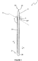
Figure 1 is a sectional isometric section view of an anchoring device according to a first embodiment installed at a site of use; -
Figure 2 is a longitudinal section view of the anchoring device ofFigure 1 ; -
Figure 3 is a section view of the anchoring device ofFigure 1 taken through line A-A ofFigure 1 ; -
Figure 4 is an enlarged view of the anchoring device ofFigure 1 during installation at a site of use; -
Figure 5 is a schematic representation of part of an anchoring system including a drilling apparatus and an anchoring device; and -
Figure 6 is an isometric view of an axially toothed system. - Referring now to
Figure 1 , there is shown an anchoring device oranchor 1 according to one embodiment engaging a bearing plate BP on a substrate S. Theanchoring device 1 includes adrill rod 2, ananchor sleeve 3 and a washer (resilient element) 4. Theanchoring device 1 is shown installed in a subsea seabed substrate S composed of stratified rock to provide a location for a tether (not shown) for restraining subsea pipelines. In some embodiments, theanchoring device 1 may find other alternative uses, for example to maintain the integrity of a rock wall. - Referring now to
Figures 1 to 3 , thedrill rod 2 is an elongate member formed from steel, most preferably super duplex steel, and having a first, driving end 20 and a second, drilling end 21 connected by ashaft 22. Theouter surface 23 of theshaft 22 includes a continuoushelical groove 24, for the transport of spoil, and extends from the drilling end 21 to the driving end 20. The driving end 20 includes aconnection pin 25 configured for releasable connection with a drilling apparatus (10 inFigure 5 ). The drilling end 21 includes adrilling head 26 with cuttingedges 27, where thedrilling head 26 has an external dimension d1. Theanchor sleeve 3 is also formed from steel, most preferably super duplex steel, and has a cylindricalhollow body 30 with adistal end 31 and aproximal end 32. Thebody 30 is split longitudinally in such a way that it has a segment shaped discontinuity orslot 33 in plan view. In this way theanchor sleeve 3 may be partially compressed diametrically by the application of an external force, but, upon release of that external force, will resiliently return to its original shape due to the inherent resilience of the super duplex steel. - An
integral flange 34 projects outwardly from thedistal end 31 of thebody 30, theflange 34 having an upper, engaging face 35 and a lower, pressingface 36. - At the
proximal end 32 the outer surface of thehollow body 30 includes ataper 37. The inner diameter d2 of thehollow body 30 is configured to be slightly less than the external dimension d1 of thedrilling head 26. - A plurality of
barbs 38 are included on the outer surface of thehollow body 30 and oriented towards theproximal end 32 thereof. Pluralstress relieving channels 39 extend longitudinally into the outer surface of thehollow body 30, regularly spaced circumferentially. Thestress relieving channels 39 allow a change in diameter of the anchor sleeve and therefore affects the radial loading it is subjected to. - A spring, preload or waved
washer 4 is provided adjacent theflange 34 of theanchor sleeve 3. Thewasher 4 is of polyurethane in this example (but could be other suitable materials, or could be a Belville type sprung washer). The washer may extend further outwards radially than theflange 34. Thewasher 4 is provided at the lower face 36 (i.e. facing the body 30). - Referring now to
Figures 4 and5 , there is shown ananchoring device 1 being installed in a substrate using andrilling apparatus 10 which includes amotor 11, a connector or chuck 12, anengagement collar 13 and anarmature 14. - The
motor 11, which is of a standard type suitable for subsea use, depends from a lower surface of thearmature 14. Theconnection pin 25 of theanchoring device 1 is connected to themotor 11 via theconnector 12. Theengagement collar 13 includes anaperture 13a configured to encompass, in a non-contact fashion, theshaft 22 of thedrill rod 2 which may therefore pass freely through theaperture 13a. Theengagement collar 13 has a substantially flatlower surface 13b suitable for engagement with the engagement surface 35 of theflange 34 of theanchor sleeve 3. Abracket 15 rigidly fixes theengagement collar 13 to thearmature 14. - In use, a substantially flat steel bearing plate BP, including a circular aperture (not shown) through its thickness, is affixed on a substrate S at an intended site of use. The diameter of the aperture is configured to allow free passage therethrough of the
body 30 of theanchor sleeve 3 but to abut the outwardly projectingflange 34 thereof. A spring, preload or wavedwasher 4 is located around the aperture of the bearing plate BP, in this case aspring washer 4. - The
drilling apparatus 10 is positioned at the intended site of use, such that thedrill head 26 of theanchoring device 1 is aligned with the aperture of the bearing plate BP and thespring washer 4. Thearmature 14, of which only a portion is shown inFigure 5 , is driven downwards along the length of theanchoring device 1 in the direction of arrow B. Thearmature 14 may be driven by any suitable means, for example pneumatic or hydraulic actuation (neither of which is shown). - The
motor 11 is then activated thereby causing theanchoring device 1 to rotate. The cutting surfaces 27 of thedrill head 26 cut into the substrate S upon engagement therewith, thereby drilling a hole thereinto. As theanchoring device 1 is pushed into the thus formed hole, spoil from the drilled substrate S is transported from the hole along thehelical groove 24 on the outside of theshaft 22. - Simultaneously, the
lower surface 13b of theengagement collar 13 engages the engaging face 35 of theanchor sleeve 3, pushing it into the hole in the substrate S, in concert with thedrill rod 2. Thedrilling head 26 drills a hole having a diameter which is less than the outer diameter of theanchor sleeve 3. Thetaper 37 at thedistal end 32 of theanchor sleeve 3 engages the drilled hole first. Theanchor sleeve 3 is compressed diametrically during its insertion into the drilled hole, as a consequence of the difference in diameter of the drilled hole and the outer surface of theanchor sleeve 3. Due to the diametric compression of theanchor sleeve 3 the outer surface thereof is radially biased against the inner wall of the drilled hole, providing a frictional gripping force thereagainst. - The
drill rod 2 is drilled into the substrate S until thepressing face 36 of theflange 34 of theanchor sleeve 3 engages thespring washer 4, compressing it against the bearing plate BP. The downward force applied to thedrilling apparatus 10 is subsequently removed and themotor 11 disconnected from theconnection pin 25 of thedrilling rod 2. Thus released from thedrilling apparatus 10, thespring washer 4 resiliently urges theflange 34 of theanchor sleeve 3 away from the bearing plate BP. Theanchor sleeve 3 is therefore urged back along the path of its previous travel, whereby theanchor sleeve 3 is secured in place. - The
anchor sleeve 3 is secured in place either through friction between the outer surface of the anchoring sleeve and the inner wall of the drilled hole or through gripping means,e.g. barbs 38 on the outer surface of theanchor sleeve 3, which are forced into the inner wall of the drilled hole as theanchor sleeve 3 is urged back along the path of its previous travel. Thedrilling head 26 of thedrill rod 2 has a greater external dimension d1 than the internal diameter d2 of theanchor sleeve 3, as described above, and therefore thedrill rod 2 is retained by theanchor sleeve 3 within the drilled hole. - Aptly, to allow the drill rod to unlatch, the drill rod is not captive to the drill. The apparatus may include an axially toothed system so as to allow compressive loads to be transmitted to the drill rod during drilling, but not allowing tensile loads. For example, such system may be part of the connector or
chuck 12. Alternatively the system may be a separate component between the drill rod and the connector. An example is shown inFig. 6 in which twoportions portions - The resilience of the spring washer 4 (or other resilient element) in urging the anchor sleeve back along the path of its previous travel, pre-tensions the anchor sleeve. This allows the capacity of the anchoring device (for securement of the anchoring
sleeve 3 within the strata) to be tested prior to removal of the drilling apparatus. - As with standard bolting practice, the length of the drill rod is dependent upon the load. The sleeve would not normally be taken beyond the yield point of the materials (e.g. for steels this would be about 2% strain).
- Suitably configured attachments (not shown) may then be attached to the driving end 20 of the
drill rod 2 in order to effect tethering of subsea pipelines and other subsea articles. - The
drill rod 2 remains within the drilled hole as part of theanchoring device 1 and is not therefore useable in order to drill further holes in the or another substrate S. Therefore, anew drill bit 2 is required for the drilling of each anchoringdevice 1 according to the invention, resulting in an increase in the expense of drill materials. However, the method of installation of the invention, in contrast to known methods of subsea anchoring installation, may be achieved by a fully automatic remotely operateddrilling apparatus 10. Advantageously, this automatic anchoring or installation system allows installation ofanchoring devices 1 at subsea locations and depths at which divers may not operate, and therefore may not be installed via known methods of installation. Furthermore, the method of installation of the invention requires fewer stages than known methods of installation, leading to savings in installation time and consequent expenditure savings. - It will be appreciated by those skilled in the art that several variations to the aforementioned embodiments are envisaged without departing from the scope of the invention. For example, the
anchoring device 1 may be installed at locations above the sea and/or in alternative substrates S for example in unstratified rock. Although thespring washer 4 is shown disposed between theflange 34 and the bearing plate BP it need not be and may be located at any position suitable for urging theanchor sleeve 3 outwardly from the drilled hole, for example between thedrilling head 26 and thedistal end 32 of theanchor sleeve 3. Additionally or alternatively, thespring washer 4 may be replaced by or supplemented with a spring or other resilient member. Although theanchoring device 1 is shown installed against a bearing plate BP on a substrate S it need not be and may instead be installed directly against the substrate S. Additionally or alternatively, although theengagement collar 13 is shown as being fixed to thearmature 14 it need not be and may instead be fixed to themotor 11 or a further component of thedrilling apparatus 10 by any suitable means. - It will also be appreciated by those skilled in the art that any number of combinations of the aforementioned features and/or those shown in the appended drawings provide clear advantages over the prior art and are therefore within the scope of the invention described herein.
- With the above arrangement, the unit including the drilling rod and anchoring sleeve are drilled into and remain in the drilled hole. The unit remains as a unitary piece.
- With this arrangement, an anchoring device is provided with a greater strength compared to known arrangements, e.g. allowing a flexible pipe to be tethered to the seabed.
- Throughout the description and claims of this specification, the words "comprise" and "contain" and variations of them mean "including but not limited to", and they are not intended to (and do not) exclude other moieties, additives, components, integers or steps. Throughout the description and claims of this specification, the singular encompasses the plural unless the context otherwise requires. In particular, where the indefinite article is used, the specification is to be understood as contemplating plurality as well as singularity, unless the context requires otherwise.
- Features, integers, characteristics, compounds, chemical moieties or groups described in conjunction with a particular aspect, embodiment or example of the invention are to be understood to be applicable to any other aspect, embodiment or example described herein unless incompatible therewith. All of the features disclosed in this specification (including abstract and drawings), and/or all of the steps of any method or process so disclosed, may be combined in any combination, except combinations where at least some of such features and/or steps are mutually exclusive. The invention is not restricted to the details of any foregoing embodiments. The invention is defined by the claims.
Claims (15)
- An anchoring device (1) for securement to strata, the device comprising a drilling rod (2) and an anchoring sleeve (3) at least partially surrounding the drilling rod, the drilling rod comprising a driving end (20) for coupling to a drilling apparatus and a drilling end (21) with a drilling head (26) for drilling a hole in strata, wherein the device is configured to be coupled with and driven by a drilling apparatus to cause the drilling head to drill a hole into strata and to force, as the hole is drilled, the anchoring sleeve into the hole to an inserted position in which the anchoring sleeve engages the surrounding strata;
characterised in that the anchoring sleeve (3) comprises gripping means on its outer surface for engaging the surrounding strata,
wherein the anchoring sleeve (3) comprises a flange (34) adjacent the driving end (20) of the drilling rod (2),
wherein the anchoring device further comprises a resilient element (4) at least partially surrounding the anchoring sleeve (3) and configured to be compressed, in use, between the flange (34) and the strata when the anchoring sleeve is in the inserted position, thereby to urge the anchoring sleeve along a direction that is opposite to the drilling direction. - Anchoring device (1) according to claim 1 comprising a resilient biasing means configured to bias the anchoring sleeve (3) into engagement with surrounding strata when it is in the inserted position.
- Anchoring device (1) according to claim 1 or claim 2, wherein the drilling head (26) is configured to drill a hole that is smaller than the outer dimension of the anchoring sleeve (3) such that the anchoring sleeve is in interference fit with the hole; and optionally
wherein the anchoring sleeve (3) is formed of a material that is elastically deformable so as to bias, in use, resiliently the anchoring sleeve against the surrounding strata. - Anchoring device according to claim 1, wherein the gripping means comprises a plurality of barbs (38); and/or
wherein the anchoring sleeve (3) comprises a longitudinal slot (33) along at least a portion of its length. - Anchoring device (1) according to any preceding claim, wherein the anchoring sleeve (3) comprises one or more stress relief features for reducing, in use, the peak stress experienced by the anchoring sleeve; and optionally
wherein the or each stress relief feature comprises a longitudinal groove (39) extending along at least a portion of the length of the anchoring sleeve (3). - Anchoring device (1) according to any preceding claim, wherein the anchoring sleeve (3) comprises a driving surface (35) against which a driving collar of the drilling apparatus engages, in use, to force the anchoring sleeve into the hole.
- Anchoring device (1) according to claim 1, wherein the resilient element (4) comprises a resilient washer.
- Anchoring device (1) according to any preceding claim, wherein the drilling head (26) is larger than the internal dimension of the sleeve (3).
- Anchoring device (1) according to any preceding claim, wherein the drilling rod (2) comprises a helical flute (24) extending between the drilling head (26) and the driving end (20).
- An anchoring system comprising a drilling apparatus (10) and one or more anchoring devices (1) according to any preceding claim, wherein the drilling apparatus comprises a chuck (12) for coupling with the driving end of the drilling rod (2) and a driving collar (13) for engaging a driving surface (35) or flange (34) of the anchoring sleeve (3) to force, in use, the anchoring sleeve into the hole as the hole is drilled.
- A method of securing an anchoring device (1) to strata, the method comprising coupling a drilling apparatus (10) to the drilling end of a drilling rod (2),
driving the drilling end of the drilling rod to cause a drilling head (26) thereof to drill a hole into strata and, as the hole is drilled, forcing an anchoring sleeve (3) that at least partially surrounds the drilling rod into the hole to an inserted position in which the anchoring sleeve engages the surrounding strata,
characterised in that the anchoring sleeve (3) comprises gripping means on its the outer surface that is urged into engagement with the surrounding strata when the anchoring sleeve is in the inserted position,
wherein the anchoring sleeve (3) comprises a flange (34) adjacent the driving end (20) of the drilling rod (2), wherein a resilient element (4) that at least partially surrounds the anchoring sleeve (3) is compressed between the flange (34) and the strata as the anchoring sleeve is forced into the inserted position, thereby to urge the anchoring sleeve along a direction that is opposite to the drilling direction. - Method according to claim 11, wherein the anchoring sleeve (3) is urged into engagement with the surrounding strata by a resilient biasing means when the anchoring sleeve is in the inserted position; and/or
wherein the hole that is drilled is smaller than the outer dimension of the anchoring sleeve (3) such that the anchoring sleeve is forced into an interference fit with the hole. - Method according to claim 12, wherein the anchoring sleeve (3) is formed of a material that is elastically deformable so as to bias resiliently the anchoring sleeve against the surrounding strata.
- Method according to any one of claims 11 to 13, wherein the anchoring sleeve is forced into the hole by a collar of the drilling apparatus that engages a driving surface of the anchoring sleeve; and optionally
wherein the flange (34) of the anchoring sleeve (3) that is adjacent the driving end (20) of the drilling rod (2) is engaged by the collar (13) to force the anchoring sleeve into the hole; and optionally
wherein the method further comprises retracting the collar of the drilling apparatus out of engagement with the flange after the anchoring sleeve is forced into the inserted position such that the resilient element urges the anchoring sleeve along a direction that is opposite to the drilling direction. - Method according to any one of claims 11 to 14 comprising releasing the drilling rod (2) after the hole is drilled such that the rod remains in the hole.
Applications Claiming Priority (2)
| Application Number | Priority Date | Filing Date | Title |
|---|---|---|---|
| GBGB1513485.1A GB201513485D0 (en) | 2015-07-30 | 2015-07-30 | Anchoring device and method |
| PCT/GB2016/052331 WO2017017468A1 (en) | 2015-07-30 | 2016-07-28 | Anchoring device and method |
Publications (2)
| Publication Number | Publication Date |
|---|---|
| EP3329098A1 EP3329098A1 (en) | 2018-06-06 |
| EP3329098B1 true EP3329098B1 (en) | 2019-12-18 |
Family
ID=54062936
Family Applications (1)
| Application Number | Title | Priority Date | Filing Date |
|---|---|---|---|
| EP16747585.4A Active EP3329098B1 (en) | 2015-07-30 | 2016-07-28 | Anchoring device and method |
Country Status (5)
| Country | Link |
|---|---|
| US (1) | US20180223664A1 (en) |
| EP (1) | EP3329098B1 (en) |
| JP (1) | JP2018522155A (en) |
| GB (1) | GB201513485D0 (en) |
| WO (1) | WO2017017468A1 (en) |
Families Citing this family (1)
| Publication number | Priority date | Publication date | Assignee | Title |
|---|---|---|---|---|
| CN109339840B (en) * | 2018-11-13 | 2024-03-05 | 重庆大学 | A torsional large deformation anchor |
Family Cites Families (5)
| Publication number | Priority date | Publication date | Assignee | Title |
|---|---|---|---|---|
| US6106200A (en) * | 1996-11-12 | 2000-08-22 | Techmo Entwicklungs-Und Vertriebs Gmbh | Process and device for simultaneously drilling and lining a hole |
| AT408248B (en) * | 1997-06-18 | 2001-09-25 | Techmo Entw & Vertriebs Gmbh | METHOD AND DEVICE FOR DRILLING HOLES |
| SK286790B6 (en) * | 2001-04-26 | 2009-05-07 | "Alwag" Tunnelausbau Gesellschaft M.B.H. | Method and device for drilling a hole and for securing an anchorage in a bore hole |
| US20070269274A1 (en) * | 2003-06-03 | 2007-11-22 | Ross Seedsman | Rock Bolt |
| AT501875B1 (en) * | 2005-06-07 | 2008-05-15 | Alwag Tunnelausbau Gmbh | METHOD AND DEVICE FOR DRILLING, IN PARTICULAR FITTING OR TURNING OF A HOLE IN GROUND OR ROCK MATERIAL |
-
2015
- 2015-07-30 GB GBGB1513485.1A patent/GB201513485D0/en not_active Ceased
-
2016
- 2016-07-28 JP JP2018524567A patent/JP2018522155A/en not_active Withdrawn
- 2016-07-28 WO PCT/GB2016/052331 patent/WO2017017468A1/en not_active Ceased
- 2016-07-28 EP EP16747585.4A patent/EP3329098B1/en active Active
- 2016-07-28 US US15/748,418 patent/US20180223664A1/en not_active Abandoned
Non-Patent Citations (1)
| Title |
|---|
| None * |
Also Published As
| Publication number | Publication date |
|---|---|
| JP2018522155A (en) | 2018-08-09 |
| US20180223664A1 (en) | 2018-08-09 |
| WO2017017468A1 (en) | 2017-02-02 |
| EP3329098A1 (en) | 2018-06-06 |
| GB201513485D0 (en) | 2015-09-16 |
Similar Documents
| Publication | Publication Date | Title |
|---|---|---|
| AU2010200232B2 (en) | Rock bolt | |
| US7959379B2 (en) | Bolt anchor | |
| AU2014101640A4 (en) | Multiple-point anchored rock bolt | |
| EP3612719B1 (en) | Rock bolt installation tool | |
| US20110103896A1 (en) | Cuttable drilling tool, and a cuttable self drilling rock bolt | |
| US11066931B2 (en) | Retainer device for a rock anchor, rock anchor system and associated installation method | |
| AU2014361729A1 (en) | Ground support apparatus and method | |
| US9512685B2 (en) | Cable protector system | |
| AU2021202496B2 (en) | Improved drill bit for use with a friction bolt | |
| US20180223664A1 (en) | Anchoring Device and Method | |
| US8696249B2 (en) | Rock bolt and rock bolt component | |
| US9322228B2 (en) | Centralizer connector | |
| GB2477361A (en) | Radially expandable connector | |
| EP3530877A1 (en) | Rock bolt and method for drilling and reinforcing material | |
| EP2878835A1 (en) | Concrete masonry anchor and method of fastening | |
| US20130294844A1 (en) | Anchoring device | |
| JP6355475B2 (en) | Support structure for fixture and tunnel lining formwork | |
| RU2470136C1 (en) | Locking device for well equipped run in on string | |
| AU2019101798A4 (en) | Retainer device for a rock anchor, rock anchor system and associated installation method | |
| EP3283730A1 (en) | Improved drilling assembly comprising a friction bolt | |
| EP3530878B1 (en) | Impact absorber for rock bolt | |
| AU2022215315A1 (en) | Rock Bolt | |
| WO2009150617A1 (en) | Anchoring device |
Legal Events
| Date | Code | Title | Description |
|---|---|---|---|
| STAA | Information on the status of an ep patent application or granted ep patent |
Free format text: STATUS: THE INTERNATIONAL PUBLICATION HAS BEEN MADE |
|
| PUAI | Public reference made under article 153(3) epc to a published international application that has entered the european phase |
Free format text: ORIGINAL CODE: 0009012 |
|
| STAA | Information on the status of an ep patent application or granted ep patent |
Free format text: STATUS: REQUEST FOR EXAMINATION WAS MADE |
|
| 17P | Request for examination filed |
Effective date: 20180206 |
|
| AK | Designated contracting states |
Kind code of ref document: A1 Designated state(s): AL AT BE BG CH CY CZ DE DK EE ES FI FR GB GR HR HU IE IS IT LI LT LU LV MC MK MT NL NO PL PT RO RS SE SI SK SM TR |
|
| AX | Request for extension of the european patent |
Extension state: BA ME |
|
| RAP1 | Party data changed (applicant data changed or rights of an application transferred) |
Owner name: ROYAL IHC LIMITED |
|
| RAP1 | Party data changed (applicant data changed or rights of an application transferred) |
Owner name: IHC IQIP UK LTD |
|
| DAV | Request for validation of the european patent (deleted) | ||
| DAX | Request for extension of the european patent (deleted) | ||
| GRAP | Despatch of communication of intention to grant a patent |
Free format text: ORIGINAL CODE: EPIDOSNIGR1 |
|
| STAA | Information on the status of an ep patent application or granted ep patent |
Free format text: STATUS: GRANT OF PATENT IS INTENDED |
|
| INTG | Intention to grant announced |
Effective date: 20190710 |
|
| RIN1 | Information on inventor provided before grant (corrected) |
Inventor name: MANCHESTER, JONATHAN RALPH |
|
| GRAS | Grant fee paid |
Free format text: ORIGINAL CODE: EPIDOSNIGR3 |
|
| GRAA | (expected) grant |
Free format text: ORIGINAL CODE: 0009210 |
|
| STAA | Information on the status of an ep patent application or granted ep patent |
Free format text: STATUS: THE PATENT HAS BEEN GRANTED |
|
| AK | Designated contracting states |
Kind code of ref document: B1 Designated state(s): AL AT BE BG CH CY CZ DE DK EE ES FI FR GB GR HR HU IE IS IT LI LT LU LV MC MK MT NL NO PL PT RO RS SE SI SK SM TR |
|
| REG | Reference to a national code |
Ref country code: CH Ref legal event code: EP |
|
| REG | Reference to a national code |
Ref country code: IE Ref legal event code: FG4D |
|
| REG | Reference to a national code |
Ref country code: DE Ref legal event code: R096 Ref document number: 602016026459 Country of ref document: DE |
|
| REG | Reference to a national code |
Ref country code: AT Ref legal event code: REF Ref document number: 1214799 Country of ref document: AT Kind code of ref document: T Effective date: 20200115 |
|
| REG | Reference to a national code |
Ref country code: NL Ref legal event code: FP |
|
| PG25 | Lapsed in a contracting state [announced via postgrant information from national office to epo] |
Ref country code: SE Free format text: LAPSE BECAUSE OF FAILURE TO SUBMIT A TRANSLATION OF THE DESCRIPTION OR TO PAY THE FEE WITHIN THE PRESCRIBED TIME-LIMIT Effective date: 20191218 Ref country code: LV Free format text: LAPSE BECAUSE OF FAILURE TO SUBMIT A TRANSLATION OF THE DESCRIPTION OR TO PAY THE FEE WITHIN THE PRESCRIBED TIME-LIMIT Effective date: 20191218 Ref country code: LT Free format text: LAPSE BECAUSE OF FAILURE TO SUBMIT A TRANSLATION OF THE DESCRIPTION OR TO PAY THE FEE WITHIN THE PRESCRIBED TIME-LIMIT Effective date: 20191218 Ref country code: BG Free format text: LAPSE BECAUSE OF FAILURE TO SUBMIT A TRANSLATION OF THE DESCRIPTION OR TO PAY THE FEE WITHIN THE PRESCRIBED TIME-LIMIT Effective date: 20200318 Ref country code: NO Free format text: LAPSE BECAUSE OF FAILURE TO SUBMIT A TRANSLATION OF THE DESCRIPTION OR TO PAY THE FEE WITHIN THE PRESCRIBED TIME-LIMIT Effective date: 20200318 Ref country code: GR Free format text: LAPSE BECAUSE OF FAILURE TO SUBMIT A TRANSLATION OF THE DESCRIPTION OR TO PAY THE FEE WITHIN THE PRESCRIBED TIME-LIMIT Effective date: 20200319 Ref country code: FI Free format text: LAPSE BECAUSE OF FAILURE TO SUBMIT A TRANSLATION OF THE DESCRIPTION OR TO PAY THE FEE WITHIN THE PRESCRIBED TIME-LIMIT Effective date: 20191218 |
|
| REG | Reference to a national code |
Ref country code: LT Ref legal event code: MG4D |
|
| PG25 | Lapsed in a contracting state [announced via postgrant information from national office to epo] |
Ref country code: RS Free format text: LAPSE BECAUSE OF FAILURE TO SUBMIT A TRANSLATION OF THE DESCRIPTION OR TO PAY THE FEE WITHIN THE PRESCRIBED TIME-LIMIT Effective date: 20191218 Ref country code: HR Free format text: LAPSE BECAUSE OF FAILURE TO SUBMIT A TRANSLATION OF THE DESCRIPTION OR TO PAY THE FEE WITHIN THE PRESCRIBED TIME-LIMIT Effective date: 20191218 |
|
| PG25 | Lapsed in a contracting state [announced via postgrant information from national office to epo] |
Ref country code: AL Free format text: LAPSE BECAUSE OF FAILURE TO SUBMIT A TRANSLATION OF THE DESCRIPTION OR TO PAY THE FEE WITHIN THE PRESCRIBED TIME-LIMIT Effective date: 20191218 |
|
| PG25 | Lapsed in a contracting state [announced via postgrant information from national office to epo] |
Ref country code: CZ Free format text: LAPSE BECAUSE OF FAILURE TO SUBMIT A TRANSLATION OF THE DESCRIPTION OR TO PAY THE FEE WITHIN THE PRESCRIBED TIME-LIMIT Effective date: 20191218 Ref country code: RO Free format text: LAPSE BECAUSE OF FAILURE TO SUBMIT A TRANSLATION OF THE DESCRIPTION OR TO PAY THE FEE WITHIN THE PRESCRIBED TIME-LIMIT Effective date: 20191218 Ref country code: PT Free format text: LAPSE BECAUSE OF FAILURE TO SUBMIT A TRANSLATION OF THE DESCRIPTION OR TO PAY THE FEE WITHIN THE PRESCRIBED TIME-LIMIT Effective date: 20200513 Ref country code: EE Free format text: LAPSE BECAUSE OF FAILURE TO SUBMIT A TRANSLATION OF THE DESCRIPTION OR TO PAY THE FEE WITHIN THE PRESCRIBED TIME-LIMIT Effective date: 20191218 |
|
| PG25 | Lapsed in a contracting state [announced via postgrant information from national office to epo] |
Ref country code: IS Free format text: LAPSE BECAUSE OF FAILURE TO SUBMIT A TRANSLATION OF THE DESCRIPTION OR TO PAY THE FEE WITHIN THE PRESCRIBED TIME-LIMIT Effective date: 20200418 Ref country code: SK Free format text: LAPSE BECAUSE OF FAILURE TO SUBMIT A TRANSLATION OF THE DESCRIPTION OR TO PAY THE FEE WITHIN THE PRESCRIBED TIME-LIMIT Effective date: 20191218 Ref country code: SM Free format text: LAPSE BECAUSE OF FAILURE TO SUBMIT A TRANSLATION OF THE DESCRIPTION OR TO PAY THE FEE WITHIN THE PRESCRIBED TIME-LIMIT Effective date: 20191218 |
|
| REG | Reference to a national code |
Ref country code: DE Ref legal event code: R097 Ref document number: 602016026459 Country of ref document: DE |
|
| REG | Reference to a national code |
Ref country code: AT Ref legal event code: MK05 Ref document number: 1214799 Country of ref document: AT Kind code of ref document: T Effective date: 20191218 |
|
| PLBE | No opposition filed within time limit |
Free format text: ORIGINAL CODE: 0009261 |
|
| STAA | Information on the status of an ep patent application or granted ep patent |
Free format text: STATUS: NO OPPOSITION FILED WITHIN TIME LIMIT |
|
| PG25 | Lapsed in a contracting state [announced via postgrant information from national office to epo] |
Ref country code: DK Free format text: LAPSE BECAUSE OF FAILURE TO SUBMIT A TRANSLATION OF THE DESCRIPTION OR TO PAY THE FEE WITHIN THE PRESCRIBED TIME-LIMIT Effective date: 20191218 Ref country code: ES Free format text: LAPSE BECAUSE OF FAILURE TO SUBMIT A TRANSLATION OF THE DESCRIPTION OR TO PAY THE FEE WITHIN THE PRESCRIBED TIME-LIMIT Effective date: 20191218 |
|
| 26N | No opposition filed |
Effective date: 20200921 |
|
| PG25 | Lapsed in a contracting state [announced via postgrant information from national office to epo] |
Ref country code: AT Free format text: LAPSE BECAUSE OF FAILURE TO SUBMIT A TRANSLATION OF THE DESCRIPTION OR TO PAY THE FEE WITHIN THE PRESCRIBED TIME-LIMIT Effective date: 20191218 Ref country code: SI Free format text: LAPSE BECAUSE OF FAILURE TO SUBMIT A TRANSLATION OF THE DESCRIPTION OR TO PAY THE FEE WITHIN THE PRESCRIBED TIME-LIMIT Effective date: 20191218 |
|
| PG25 | Lapsed in a contracting state [announced via postgrant information from national office to epo] |
Ref country code: IT Free format text: LAPSE BECAUSE OF FAILURE TO SUBMIT A TRANSLATION OF THE DESCRIPTION OR TO PAY THE FEE WITHIN THE PRESCRIBED TIME-LIMIT Effective date: 20191218 |
|
| PG25 | Lapsed in a contracting state [announced via postgrant information from national office to epo] |
Ref country code: PL Free format text: LAPSE BECAUSE OF FAILURE TO SUBMIT A TRANSLATION OF THE DESCRIPTION OR TO PAY THE FEE WITHIN THE PRESCRIBED TIME-LIMIT Effective date: 20191218 Ref country code: MC Free format text: LAPSE BECAUSE OF FAILURE TO SUBMIT A TRANSLATION OF THE DESCRIPTION OR TO PAY THE FEE WITHIN THE PRESCRIBED TIME-LIMIT Effective date: 20191218 |
|
| REG | Reference to a national code |
Ref country code: CH Ref legal event code: PL |
|
| REG | Reference to a national code |
Ref country code: BE Ref legal event code: MM Effective date: 20200731 |
|
| PG25 | Lapsed in a contracting state [announced via postgrant information from national office to epo] |
Ref country code: LU Free format text: LAPSE BECAUSE OF NON-PAYMENT OF DUE FEES Effective date: 20200728 Ref country code: LI Free format text: LAPSE BECAUSE OF NON-PAYMENT OF DUE FEES Effective date: 20200731 Ref country code: CH Free format text: LAPSE BECAUSE OF NON-PAYMENT OF DUE FEES Effective date: 20200731 |
|
| PG25 | Lapsed in a contracting state [announced via postgrant information from national office to epo] |
Ref country code: BE Free format text: LAPSE BECAUSE OF NON-PAYMENT OF DUE FEES Effective date: 20200731 |
|
| PG25 | Lapsed in a contracting state [announced via postgrant information from national office to epo] |
Ref country code: IE Free format text: LAPSE BECAUSE OF NON-PAYMENT OF DUE FEES Effective date: 20200728 |
|
| PG25 | Lapsed in a contracting state [announced via postgrant information from national office to epo] |
Ref country code: TR Free format text: LAPSE BECAUSE OF FAILURE TO SUBMIT A TRANSLATION OF THE DESCRIPTION OR TO PAY THE FEE WITHIN THE PRESCRIBED TIME-LIMIT Effective date: 20191218 Ref country code: MT Free format text: LAPSE BECAUSE OF FAILURE TO SUBMIT A TRANSLATION OF THE DESCRIPTION OR TO PAY THE FEE WITHIN THE PRESCRIBED TIME-LIMIT Effective date: 20191218 Ref country code: CY Free format text: LAPSE BECAUSE OF FAILURE TO SUBMIT A TRANSLATION OF THE DESCRIPTION OR TO PAY THE FEE WITHIN THE PRESCRIBED TIME-LIMIT Effective date: 20191218 |
|
| PG25 | Lapsed in a contracting state [announced via postgrant information from national office to epo] |
Ref country code: MK Free format text: LAPSE BECAUSE OF FAILURE TO SUBMIT A TRANSLATION OF THE DESCRIPTION OR TO PAY THE FEE WITHIN THE PRESCRIBED TIME-LIMIT Effective date: 20191218 |
|
| REG | Reference to a national code |
Ref country code: DE Ref legal event code: R081 Ref document number: 602016026459 Country of ref document: DE Owner name: IQIP HOLDING B.V., NL Free format text: FORMER OWNER: IHC IQIP UK LTD, WINTERBORNE STICKLAND, DORSET, GB Ref country code: DE Ref legal event code: R081 Ref document number: 602016026459 Country of ref document: DE Owner name: IHC IQIP HOLDING B.V., NL Free format text: FORMER OWNER: IHC IQIP UK LTD, WINTERBORNE STICKLAND, DORSET, GB Ref country code: DE Ref legal event code: R082 Ref document number: 602016026459 Country of ref document: DE Representative=s name: HGF EUROPE LLP, DE |
|
| PGFP | Annual fee paid to national office [announced via postgrant information from national office to epo] |
Ref country code: DE Payment date: 20220722 Year of fee payment: 7 |
|
| REG | Reference to a national code |
Ref country code: GB Ref legal event code: 732E Free format text: REGISTERED BETWEEN 20221020 AND 20221026 |
|
| REG | Reference to a national code |
Ref country code: NL Ref legal event code: PD Owner name: IHC IQIP HOLDING B.V.; NL Free format text: DETAILS ASSIGNMENT: CHANGE OF OWNER(S), ASSIGNMENT; FORMER OWNER NAME: IHC IQIP UK LTD Effective date: 20221219 |
|
| REG | Reference to a national code |
Ref country code: NL Ref legal event code: HC Owner name: IQIP HOLDING B.V.; NL Free format text: DETAILS ASSIGNMENT: CHANGE OF OWNER(S), CHANGE OF OWNER(S) NAME; FORMER OWNER NAME: IHC IQIP HOLDING B.V. Effective date: 20230330 |
|
| REG | Reference to a national code |
Ref country code: DE Ref legal event code: R081 Ref document number: 602016026459 Country of ref document: DE Owner name: IQIP HOLDING B.V., NL Free format text: FORMER OWNER: IHC IQIP HOLDING B.V., SLIEDRECHT, NL |
|
| P01 | Opt-out of the competence of the unified patent court (upc) registered |
Effective date: 20230524 |
|
| REG | Reference to a national code |
Ref country code: DE Ref legal event code: R119 Ref document number: 602016026459 Country of ref document: DE |
|
| PG25 | Lapsed in a contracting state [announced via postgrant information from national office to epo] |
Ref country code: DE Free format text: LAPSE BECAUSE OF NON-PAYMENT OF DUE FEES Effective date: 20240201 |
|
| PGFP | Annual fee paid to national office [announced via postgrant information from national office to epo] |
Ref country code: NL Payment date: 20250723 Year of fee payment: 10 |
|
| PGFP | Annual fee paid to national office [announced via postgrant information from national office to epo] |
Ref country code: GB Payment date: 20250724 Year of fee payment: 10 |
|
| PGFP | Annual fee paid to national office [announced via postgrant information from national office to epo] |
Ref country code: FR Payment date: 20250723 Year of fee payment: 10 |