EP3328618B1 - Wind turbine blade bondlines - Google Patents
Wind turbine blade bondlines Download PDFInfo
- Publication number
- EP3328618B1 EP3328618B1 EP16754184.6A EP16754184A EP3328618B1 EP 3328618 B1 EP3328618 B1 EP 3328618B1 EP 16754184 A EP16754184 A EP 16754184A EP 3328618 B1 EP3328618 B1 EP 3328618B1
- Authority
- EP
- European Patent Office
- Prior art keywords
- mounting flange
- blade shell
- shear web
- adhesive
- shell
- Prior art date
- Legal status (The legal status is an assumption and is not a legal conclusion. Google has not performed a legal analysis and makes no representation as to the accuracy of the status listed.)
- Active
Links
- 239000000853 adhesive Substances 0.000 claims description 45
- 230000001070 adhesive effect Effects 0.000 claims description 45
- 238000000034 method Methods 0.000 claims description 24
- 238000004519 manufacturing process Methods 0.000 claims description 5
- 238000004891 communication Methods 0.000 claims description 4
- 239000012530 fluid Substances 0.000 claims description 4
- 239000011324 bead Substances 0.000 description 4
- 239000000463 material Substances 0.000 description 3
- 239000003365 glass fiber Substances 0.000 description 2
- OKTJSMMVPCPJKN-UHFFFAOYSA-N Carbon Chemical compound [C] OKTJSMMVPCPJKN-UHFFFAOYSA-N 0.000 description 1
- 229920002430 Fibre-reinforced plastic Polymers 0.000 description 1
- 229920005549 butyl rubber Polymers 0.000 description 1
- 229910052799 carbon Inorganic materials 0.000 description 1
- 239000002131 composite material Substances 0.000 description 1
- 239000011162 core material Substances 0.000 description 1
- 229920006332 epoxy adhesive Polymers 0.000 description 1
- 239000004744 fabric Substances 0.000 description 1
- 239000000835 fiber Substances 0.000 description 1
- 239000006260 foam Substances 0.000 description 1
- 239000012528 membrane Substances 0.000 description 1
- 238000012986 modification Methods 0.000 description 1
- 230000004048 modification Effects 0.000 description 1
- 230000002787 reinforcement Effects 0.000 description 1
Images


Classifications
-
- B—PERFORMING OPERATIONS; TRANSPORTING
- B29—WORKING OF PLASTICS; WORKING OF SUBSTANCES IN A PLASTIC STATE IN GENERAL
- B29C—SHAPING OR JOINING OF PLASTICS; SHAPING OF MATERIAL IN A PLASTIC STATE, NOT OTHERWISE PROVIDED FOR; AFTER-TREATMENT OF THE SHAPED PRODUCTS, e.g. REPAIRING
- B29C65/00—Joining or sealing of preformed parts, e.g. welding of plastics materials; Apparatus therefor
- B29C65/48—Joining or sealing of preformed parts, e.g. welding of plastics materials; Apparatus therefor using adhesives, i.e. using supplementary joining material; solvent bonding
- B29C65/4805—Joining or sealing of preformed parts, e.g. welding of plastics materials; Apparatus therefor using adhesives, i.e. using supplementary joining material; solvent bonding characterised by the type of adhesives
- B29C65/483—Reactive adhesives, e.g. chemically curing adhesives
-
- B—PERFORMING OPERATIONS; TRANSPORTING
- B29—WORKING OF PLASTICS; WORKING OF SUBSTANCES IN A PLASTIC STATE IN GENERAL
- B29C—SHAPING OR JOINING OF PLASTICS; SHAPING OF MATERIAL IN A PLASTIC STATE, NOT OTHERWISE PROVIDED FOR; AFTER-TREATMENT OF THE SHAPED PRODUCTS, e.g. REPAIRING
- B29C65/00—Joining or sealing of preformed parts, e.g. welding of plastics materials; Apparatus therefor
- B29C65/78—Means for handling the parts to be joined, e.g. for making containers or hollow articles, e.g. means for handling sheets, plates, web-like materials, tubular articles, hollow articles or elements to be joined therewith; Means for discharging the joined articles from the joining apparatus
- B29C65/7802—Positioning the parts to be joined, e.g. aligning, indexing or centring
- B29C65/782—Positioning the parts to be joined, e.g. aligning, indexing or centring by setting the gap between the parts to be joined
- B29C65/7823—Positioning the parts to be joined, e.g. aligning, indexing or centring by setting the gap between the parts to be joined by using distance pieces, i.e. by using spacers positioned between the parts to be joined and forming a part of the joint
- B29C65/7829—Positioning the parts to be joined, e.g. aligning, indexing or centring by setting the gap between the parts to be joined by using distance pieces, i.e. by using spacers positioned between the parts to be joined and forming a part of the joint said distance pieces being integral with at least one of the parts to be joined
-
- B—PERFORMING OPERATIONS; TRANSPORTING
- B29—WORKING OF PLASTICS; WORKING OF SUBSTANCES IN A PLASTIC STATE IN GENERAL
- B29C—SHAPING OR JOINING OF PLASTICS; SHAPING OF MATERIAL IN A PLASTIC STATE, NOT OTHERWISE PROVIDED FOR; AFTER-TREATMENT OF THE SHAPED PRODUCTS, e.g. REPAIRING
- B29C66/00—General aspects of processes or apparatus for joining preformed parts
- B29C66/001—Joining in special atmospheres
- B29C66/0012—Joining in special atmospheres characterised by the type of environment
- B29C66/0014—Gaseous environments
- B29C66/00145—Vacuum, e.g. partial vacuum
-
- B—PERFORMING OPERATIONS; TRANSPORTING
- B29—WORKING OF PLASTICS; WORKING OF SUBSTANCES IN A PLASTIC STATE IN GENERAL
- B29C—SHAPING OR JOINING OF PLASTICS; SHAPING OF MATERIAL IN A PLASTIC STATE, NOT OTHERWISE PROVIDED FOR; AFTER-TREATMENT OF THE SHAPED PRODUCTS, e.g. REPAIRING
- B29C66/00—General aspects of processes or apparatus for joining preformed parts
- B29C66/01—General aspects dealing with the joint area or with the area to be joined
- B29C66/05—Particular design of joint configurations
- B29C66/10—Particular design of joint configurations particular design of the joint cross-sections
- B29C66/11—Joint cross-sections comprising a single joint-segment, i.e. one of the parts to be joined comprising a single joint-segment in the joint cross-section
- B29C66/112—Single lapped joints
-
- B—PERFORMING OPERATIONS; TRANSPORTING
- B29—WORKING OF PLASTICS; WORKING OF SUBSTANCES IN A PLASTIC STATE IN GENERAL
- B29C—SHAPING OR JOINING OF PLASTICS; SHAPING OF MATERIAL IN A PLASTIC STATE, NOT OTHERWISE PROVIDED FOR; AFTER-TREATMENT OF THE SHAPED PRODUCTS, e.g. REPAIRING
- B29C66/00—General aspects of processes or apparatus for joining preformed parts
- B29C66/01—General aspects dealing with the joint area or with the area to be joined
- B29C66/05—Particular design of joint configurations
- B29C66/10—Particular design of joint configurations particular design of the joint cross-sections
- B29C66/11—Joint cross-sections comprising a single joint-segment, i.e. one of the parts to be joined comprising a single joint-segment in the joint cross-section
- B29C66/114—Single butt joints
- B29C66/1142—Single butt to butt joints
-
- B—PERFORMING OPERATIONS; TRANSPORTING
- B29—WORKING OF PLASTICS; WORKING OF SUBSTANCES IN A PLASTIC STATE IN GENERAL
- B29C—SHAPING OR JOINING OF PLASTICS; SHAPING OF MATERIAL IN A PLASTIC STATE, NOT OTHERWISE PROVIDED FOR; AFTER-TREATMENT OF THE SHAPED PRODUCTS, e.g. REPAIRING
- B29C66/00—General aspects of processes or apparatus for joining preformed parts
- B29C66/01—General aspects dealing with the joint area or with the area to be joined
- B29C66/05—Particular design of joint configurations
- B29C66/10—Particular design of joint configurations particular design of the joint cross-sections
- B29C66/13—Single flanged joints; Fin-type joints; Single hem joints; Edge joints; Interpenetrating fingered joints; Other specific particular designs of joint cross-sections not provided for in groups B29C66/11 - B29C66/12
- B29C66/131—Single flanged joints, i.e. one of the parts to be joined being rigid and flanged in the joint area
-
- B—PERFORMING OPERATIONS; TRANSPORTING
- B29—WORKING OF PLASTICS; WORKING OF SUBSTANCES IN A PLASTIC STATE IN GENERAL
- B29C—SHAPING OR JOINING OF PLASTICS; SHAPING OF MATERIAL IN A PLASTIC STATE, NOT OTHERWISE PROVIDED FOR; AFTER-TREATMENT OF THE SHAPED PRODUCTS, e.g. REPAIRING
- B29C66/00—General aspects of processes or apparatus for joining preformed parts
- B29C66/01—General aspects dealing with the joint area or with the area to be joined
- B29C66/32—Measures for keeping the burr form under control; Avoiding burr formation; Shaping the burr
- B29C66/324—Avoiding burr formation
- B29C66/3242—Avoiding burr formation on the inside of a tubular or hollow article
-
- B—PERFORMING OPERATIONS; TRANSPORTING
- B29—WORKING OF PLASTICS; WORKING OF SUBSTANCES IN A PLASTIC STATE IN GENERAL
- B29C—SHAPING OR JOINING OF PLASTICS; SHAPING OF MATERIAL IN A PLASTIC STATE, NOT OTHERWISE PROVIDED FOR; AFTER-TREATMENT OF THE SHAPED PRODUCTS, e.g. REPAIRING
- B29C66/00—General aspects of processes or apparatus for joining preformed parts
- B29C66/50—General aspects of joining tubular articles; General aspects of joining long products, i.e. bars or profiled elements; General aspects of joining single elements to tubular articles, hollow articles or bars; General aspects of joining several hollow-preforms to form hollow or tubular articles
- B29C66/51—Joining tubular articles, profiled elements or bars; Joining single elements to tubular articles, hollow articles or bars; Joining several hollow-preforms to form hollow or tubular articles
- B29C66/52—Joining tubular articles, bars or profiled elements
- B29C66/524—Joining profiled elements
-
- B—PERFORMING OPERATIONS; TRANSPORTING
- B29—WORKING OF PLASTICS; WORKING OF SUBSTANCES IN A PLASTIC STATE IN GENERAL
- B29C—SHAPING OR JOINING OF PLASTICS; SHAPING OF MATERIAL IN A PLASTIC STATE, NOT OTHERWISE PROVIDED FOR; AFTER-TREATMENT OF THE SHAPED PRODUCTS, e.g. REPAIRING
- B29C66/00—General aspects of processes or apparatus for joining preformed parts
- B29C66/50—General aspects of joining tubular articles; General aspects of joining long products, i.e. bars or profiled elements; General aspects of joining single elements to tubular articles, hollow articles or bars; General aspects of joining several hollow-preforms to form hollow or tubular articles
- B29C66/51—Joining tubular articles, profiled elements or bars; Joining single elements to tubular articles, hollow articles or bars; Joining several hollow-preforms to form hollow or tubular articles
- B29C66/53—Joining single elements to tubular articles, hollow articles or bars
- B29C66/532—Joining single elements to the wall of tubular articles, hollow articles or bars
-
- B—PERFORMING OPERATIONS; TRANSPORTING
- B29—WORKING OF PLASTICS; WORKING OF SUBSTANCES IN A PLASTIC STATE IN GENERAL
- B29C—SHAPING OR JOINING OF PLASTICS; SHAPING OF MATERIAL IN A PLASTIC STATE, NOT OTHERWISE PROVIDED FOR; AFTER-TREATMENT OF THE SHAPED PRODUCTS, e.g. REPAIRING
- B29C66/00—General aspects of processes or apparatus for joining preformed parts
- B29C66/50—General aspects of joining tubular articles; General aspects of joining long products, i.e. bars or profiled elements; General aspects of joining single elements to tubular articles, hollow articles or bars; General aspects of joining several hollow-preforms to form hollow or tubular articles
- B29C66/51—Joining tubular articles, profiled elements or bars; Joining single elements to tubular articles, hollow articles or bars; Joining several hollow-preforms to form hollow or tubular articles
- B29C66/54—Joining several hollow-preforms, e.g. half-shells, to form hollow articles, e.g. for making balls, containers; Joining several hollow-preforms, e.g. half-cylinders, to form tubular articles
- B29C66/543—Joining several hollow-preforms, e.g. half-shells, to form hollow articles, e.g. for making balls, containers; Joining several hollow-preforms, e.g. half-cylinders, to form tubular articles joining more than two hollow-preforms to form said hollow articles
-
- B—PERFORMING OPERATIONS; TRANSPORTING
- B29—WORKING OF PLASTICS; WORKING OF SUBSTANCES IN A PLASTIC STATE IN GENERAL
- B29C—SHAPING OR JOINING OF PLASTICS; SHAPING OF MATERIAL IN A PLASTIC STATE, NOT OTHERWISE PROVIDED FOR; AFTER-TREATMENT OF THE SHAPED PRODUCTS, e.g. REPAIRING
- B29C66/00—General aspects of processes or apparatus for joining preformed parts
- B29C66/50—General aspects of joining tubular articles; General aspects of joining long products, i.e. bars or profiled elements; General aspects of joining single elements to tubular articles, hollow articles or bars; General aspects of joining several hollow-preforms to form hollow or tubular articles
- B29C66/61—Joining from or joining on the inside
-
- B—PERFORMING OPERATIONS; TRANSPORTING
- B29—WORKING OF PLASTICS; WORKING OF SUBSTANCES IN A PLASTIC STATE IN GENERAL
- B29C—SHAPING OR JOINING OF PLASTICS; SHAPING OF MATERIAL IN A PLASTIC STATE, NOT OTHERWISE PROVIDED FOR; AFTER-TREATMENT OF THE SHAPED PRODUCTS, e.g. REPAIRING
- B29C66/00—General aspects of processes or apparatus for joining preformed parts
- B29C66/50—General aspects of joining tubular articles; General aspects of joining long products, i.e. bars or profiled elements; General aspects of joining single elements to tubular articles, hollow articles or bars; General aspects of joining several hollow-preforms to form hollow or tubular articles
- B29C66/63—Internally supporting the article during joining
- B29C66/636—Internally supporting the article during joining using a support which remains in the joined object
-
- B—PERFORMING OPERATIONS; TRANSPORTING
- B29—WORKING OF PLASTICS; WORKING OF SUBSTANCES IN A PLASTIC STATE IN GENERAL
- B29C—SHAPING OR JOINING OF PLASTICS; SHAPING OF MATERIAL IN A PLASTIC STATE, NOT OTHERWISE PROVIDED FOR; AFTER-TREATMENT OF THE SHAPED PRODUCTS, e.g. REPAIRING
- B29C66/00—General aspects of processes or apparatus for joining preformed parts
- B29C66/80—General aspects of machine operations or constructions and parts thereof
- B29C66/81—General aspects of the pressing elements, i.e. the elements applying pressure on the parts to be joined in the area to be joined, e.g. the welding jaws or clamps
- B29C66/814—General aspects of the pressing elements, i.e. the elements applying pressure on the parts to be joined in the area to be joined, e.g. the welding jaws or clamps characterised by the design of the pressing elements, e.g. of the welding jaws or clamps
- B29C66/8141—General aspects of the pressing elements, i.e. the elements applying pressure on the parts to be joined in the area to be joined, e.g. the welding jaws or clamps characterised by the design of the pressing elements, e.g. of the welding jaws or clamps characterised by the surface geometry of the part of the pressing elements, e.g. welding jaws or clamps, coming into contact with the parts to be joined
- B29C66/81411—General aspects of the pressing elements, i.e. the elements applying pressure on the parts to be joined in the area to be joined, e.g. the welding jaws or clamps characterised by the design of the pressing elements, e.g. of the welding jaws or clamps characterised by the surface geometry of the part of the pressing elements, e.g. welding jaws or clamps, coming into contact with the parts to be joined characterised by its cross-section, e.g. transversal or longitudinal, being non-flat
- B29C66/81421—General aspects of the pressing elements, i.e. the elements applying pressure on the parts to be joined in the area to be joined, e.g. the welding jaws or clamps characterised by the design of the pressing elements, e.g. of the welding jaws or clamps characterised by the surface geometry of the part of the pressing elements, e.g. welding jaws or clamps, coming into contact with the parts to be joined characterised by its cross-section, e.g. transversal or longitudinal, being non-flat being convex or concave
- B29C66/81423—General aspects of the pressing elements, i.e. the elements applying pressure on the parts to be joined in the area to be joined, e.g. the welding jaws or clamps characterised by the design of the pressing elements, e.g. of the welding jaws or clamps characterised by the surface geometry of the part of the pressing elements, e.g. welding jaws or clamps, coming into contact with the parts to be joined characterised by its cross-section, e.g. transversal or longitudinal, being non-flat being convex or concave being concave
-
- B—PERFORMING OPERATIONS; TRANSPORTING
- B29—WORKING OF PLASTICS; WORKING OF SUBSTANCES IN A PLASTIC STATE IN GENERAL
- B29C—SHAPING OR JOINING OF PLASTICS; SHAPING OF MATERIAL IN A PLASTIC STATE, NOT OTHERWISE PROVIDED FOR; AFTER-TREATMENT OF THE SHAPED PRODUCTS, e.g. REPAIRING
- B29C66/00—General aspects of processes or apparatus for joining preformed parts
- B29C66/80—General aspects of machine operations or constructions and parts thereof
- B29C66/83—General aspects of machine operations or constructions and parts thereof characterised by the movement of the joining or pressing tools
- B29C66/832—Reciprocating joining or pressing tools
- B29C66/8322—Joining or pressing tools reciprocating along one axis
-
- F—MECHANICAL ENGINEERING; LIGHTING; HEATING; WEAPONS; BLASTING
- F03—MACHINES OR ENGINES FOR LIQUIDS; WIND, SPRING, OR WEIGHT MOTORS; PRODUCING MECHANICAL POWER OR A REACTIVE PROPULSIVE THRUST, NOT OTHERWISE PROVIDED FOR
- F03D—WIND MOTORS
- F03D1/00—Wind motors with rotation axis substantially parallel to the air flow entering the rotor
- F03D1/06—Rotors
- F03D1/065—Rotors characterised by their construction elements
- F03D1/0675—Rotors characterised by their construction elements of the blades
-
- B—PERFORMING OPERATIONS; TRANSPORTING
- B29—WORKING OF PLASTICS; WORKING OF SUBSTANCES IN A PLASTIC STATE IN GENERAL
- B29C—SHAPING OR JOINING OF PLASTICS; SHAPING OF MATERIAL IN A PLASTIC STATE, NOT OTHERWISE PROVIDED FOR; AFTER-TREATMENT OF THE SHAPED PRODUCTS, e.g. REPAIRING
- B29C65/00—Joining or sealing of preformed parts, e.g. welding of plastics materials; Apparatus therefor
- B29C65/78—Means for handling the parts to be joined, e.g. for making containers or hollow articles, e.g. means for handling sheets, plates, web-like materials, tubular articles, hollow articles or elements to be joined therewith; Means for discharging the joined articles from the joining apparatus
- B29C65/7802—Positioning the parts to be joined, e.g. aligning, indexing or centring
- B29C65/782—Positioning the parts to be joined, e.g. aligning, indexing or centring by setting the gap between the parts to be joined
- B29C65/7823—Positioning the parts to be joined, e.g. aligning, indexing or centring by setting the gap between the parts to be joined by using distance pieces, i.e. by using spacers positioned between the parts to be joined and forming a part of the joint
- B29C65/7826—Positioning the parts to be joined, e.g. aligning, indexing or centring by setting the gap between the parts to be joined by using distance pieces, i.e. by using spacers positioned between the parts to be joined and forming a part of the joint said distance pieces being non-integral with the parts to be joined, e.g. particles
-
- B—PERFORMING OPERATIONS; TRANSPORTING
- B29—WORKING OF PLASTICS; WORKING OF SUBSTANCES IN A PLASTIC STATE IN GENERAL
- B29C—SHAPING OR JOINING OF PLASTICS; SHAPING OF MATERIAL IN A PLASTIC STATE, NOT OTHERWISE PROVIDED FOR; AFTER-TREATMENT OF THE SHAPED PRODUCTS, e.g. REPAIRING
- B29C66/00—General aspects of processes or apparatus for joining preformed parts
- B29C66/01—General aspects dealing with the joint area or with the area to be joined
- B29C66/05—Particular design of joint configurations
- B29C66/301—Three-dimensional joints, i.e. the joined area being substantially non-flat
-
- B—PERFORMING OPERATIONS; TRANSPORTING
- B29—WORKING OF PLASTICS; WORKING OF SUBSTANCES IN A PLASTIC STATE IN GENERAL
- B29C—SHAPING OR JOINING OF PLASTICS; SHAPING OF MATERIAL IN A PLASTIC STATE, NOT OTHERWISE PROVIDED FOR; AFTER-TREATMENT OF THE SHAPED PRODUCTS, e.g. REPAIRING
- B29C66/00—General aspects of processes or apparatus for joining preformed parts
- B29C66/01—General aspects dealing with the joint area or with the area to be joined
- B29C66/32—Measures for keeping the burr form under control; Avoiding burr formation; Shaping the burr
- B29C66/322—Providing cavities in the joined article to collect the burr
-
- B—PERFORMING OPERATIONS; TRANSPORTING
- B29—WORKING OF PLASTICS; WORKING OF SUBSTANCES IN A PLASTIC STATE IN GENERAL
- B29C—SHAPING OR JOINING OF PLASTICS; SHAPING OF MATERIAL IN A PLASTIC STATE, NOT OTHERWISE PROVIDED FOR; AFTER-TREATMENT OF THE SHAPED PRODUCTS, e.g. REPAIRING
- B29C66/00—General aspects of processes or apparatus for joining preformed parts
- B29C66/70—General aspects of processes or apparatus for joining preformed parts characterised by the composition, physical properties or the structure of the material of the parts to be joined; Joining with non-plastics material
- B29C66/72—General aspects of processes or apparatus for joining preformed parts characterised by the composition, physical properties or the structure of the material of the parts to be joined; Joining with non-plastics material characterised by the structure of the material of the parts to be joined
- B29C66/721—Fibre-reinforced materials
- B29C66/7212—Fibre-reinforced materials characterised by the composition of the fibres
-
- B—PERFORMING OPERATIONS; TRANSPORTING
- B29—WORKING OF PLASTICS; WORKING OF SUBSTANCES IN A PLASTIC STATE IN GENERAL
- B29L—INDEXING SCHEME ASSOCIATED WITH SUBCLASS B29C, RELATING TO PARTICULAR ARTICLES
- B29L2031/00—Other particular articles
- B29L2031/08—Blades for rotors, stators, fans, turbines or the like, e.g. screw propellers
- B29L2031/082—Blades, e.g. for helicopters
- B29L2031/085—Wind turbine blades
-
- Y—GENERAL TAGGING OF NEW TECHNOLOGICAL DEVELOPMENTS; GENERAL TAGGING OF CROSS-SECTIONAL TECHNOLOGIES SPANNING OVER SEVERAL SECTIONS OF THE IPC; TECHNICAL SUBJECTS COVERED BY FORMER USPC CROSS-REFERENCE ART COLLECTIONS [XRACs] AND DIGESTS
- Y02—TECHNOLOGIES OR APPLICATIONS FOR MITIGATION OR ADAPTATION AGAINST CLIMATE CHANGE
- Y02E—REDUCTION OF GREENHOUSE GAS [GHG] EMISSIONS, RELATED TO ENERGY GENERATION, TRANSMISSION OR DISTRIBUTION
- Y02E10/00—Energy generation through renewable energy sources
- Y02E10/70—Wind energy
- Y02E10/72—Wind turbines with rotation axis in wind direction
-
- Y—GENERAL TAGGING OF NEW TECHNOLOGICAL DEVELOPMENTS; GENERAL TAGGING OF CROSS-SECTIONAL TECHNOLOGIES SPANNING OVER SEVERAL SECTIONS OF THE IPC; TECHNICAL SUBJECTS COVERED BY FORMER USPC CROSS-REFERENCE ART COLLECTIONS [XRACs] AND DIGESTS
- Y02—TECHNOLOGIES OR APPLICATIONS FOR MITIGATION OR ADAPTATION AGAINST CLIMATE CHANGE
- Y02P—CLIMATE CHANGE MITIGATION TECHNOLOGIES IN THE PRODUCTION OR PROCESSING OF GOODS
- Y02P70/00—Climate change mitigation technologies in the production process for final industrial or consumer products
- Y02P70/50—Manufacturing or production processes characterised by the final manufactured product
Definitions
- the present invention relates generally to the manufacture of wind turbine blades, and more specifically to an improved method of bonding a shear web to a wind turbine blade shell.
- Wind turbine blades such as the long blades employed on modern utility-scale wind turbines, generally comprise a substantially hollow blade shell made primarily of composite materials, such as glass-fibre reinforced plastic.
- FIG 1 shows a cross-sectional view of a known wind turbine blade 10.
- the blade shell is made up of two half shells, a windward shell 12 and a leeward shell 14, which are bonded together along the leading edge 16 and trailing edge 18 of the respective half shells 12, 14.
- Each half shell 12, 14 is made up of a plurality of glass-fibre fabric layers and other structural components such as foam core material 20 and carbon fibre reinforcements 22.
- a pair of shear webs 24 are bonded between the respective half shells 12, 14.
- the shear webs 24 are longitudinally-extending structures that bridge the two half shells 12, 14 of the blade 10 and serve to transfer shear loads from the blade 10 to a wind turbine hub in use.
- the shear webs 24 are I-beams, i.e. each shear web 24 is substantially I-shaped in cross section, and comprises a generally vertical web 26 disposed between upper and lower mounting flanges 28, 30.
- the upper and lower mounting flanges 28, 30 are arranged transversely to the web 26 and define substantially flat surfaces for mounting the shear web 24 to the leeward and windward blade shells 14, 12 respectively.
- each shear web 24 is bonded to a respective shear web mounting region 32 defined on an inner surface 34 of the windward half shell 12, whilst the upper mounting flange 28 of each shear web 24 is bonded to a respective shear web mounting region 36 defined on an inner surface 38 of the leeward half shell 14.
- a single shear web may be used.
- FIG. 2a this shows a mould 40 for the wind turbine blade 10 divided into two female half moulds, a windward mould 42 and a leeward mould 44, which are arranged side by side in an open configuration of the mould 40.
- the windward blade shell 12 and the leeward blade shell 14 are moulded separately in their respective mould halves 42, 44.
- the windward blade shell 12 is supported on a mould surface 46 of the windward mould 42 and the leeward blade shell 14 is supported on a mould surface 48 of the leeward mould 44.
- adhesive is applied along the leading edge 16 and trailing edge 18 of the windward half shell 12, and/or along the leading edge 16 and trailing edge 18 of the leeward half shell 14. Adhesive is also applied along the shear web mounting regions 32 defined on the inner surface 34 of the windward half shell 12. Further adhesive is applied along the upper mounting flanges 28 of the shear webs 24 (see Figure 2b ).
- the leeward mould 44 including the leeward blade shell 14 is lifted, turned and placed on top of the windward blade mould 42.
- This process is referred to as 'closing the mould'.
- the adhesive between the respective half shells 12, 14 and the adhesive between the shear webs 24 and the half shells 12, 14 is squeezed at these respective interfaces.
- the mould 40 With the mould 40 remaining closed, the adhesive is left to cure, i.e. harden.
- the mould 40 is then opened and the completed blade 10 is removed. The cured adhesive firmly bonds the half shells 12, 14 together and firmly bonds the shear webs 24 to the half shells 12, 14.
- WO2014/086703 describes a method of adhesively joining surfaces in a wind turbine blade by using adhesive arrestor rails.
- a method of bonding a shear web to a wind turbine blade shell comprising: providing a seal around a periphery of the mounting flange; applying adhesive to an inner surface of the blade shell or to the mounting flange; positioning the shear web relative to the blade shell, after the step of applying adhesive, such that the mounting flange is in mutually opposed relation with the inner surface of the blade shell and such that the seal defines a substantially enclosed cavity between the mounting flange and the inner surface of the blade shell, the cavity containing the adhesive; evacuating air from the cavity such that the mounting flange and the blade shell are forced together; and curing the adhesive.
- the method of the present invention is a repeatable process that creates consistently well-defined bondlines.
- the bondline is defined by the dimensions of the cavity, which is filled with adhesive. Wastage of adhesive is eliminated because the adhesive is contained within the cavity and there is no 'squeeze out' of adhesive. Accordingly, the material cost of the adhesive and the overall weight of the blade is reduced in comparison to the prior art bonding process.
- the blade shell and the mounting flange are pulled together so that the adhesive is compressed within the cavity. As the air is evacuated, this creates a force between the mounting flange and the blade shell which is uniform over the area between the mounting flange and the blade shell. This provides a constant pressure over the area of the adhesive such that it creates a bond line with a uniform thickness.
- the mounting flange and the blade shell are forced together. This means that the two parts are pulled together under the influence of a vacuum or partial vacuum in the enclosed cavity. Air is evacuated from the cavity such that the air pressure in the cavity is below atmospheric pressure.
- the seal is integrated with the mounting flange of the shear web prior to positioning the shear web against the blade shell.
- the method preferably comprises removing air from the cavity through one or more vacuum ports in fluid communication with the cavity.
- the vacuum ports are preferably provided in the mounting flange of the shear web, but may alternatively be provided in any other suitable position such as in the seal or in the blade shell.
- the invention thus provides a method of making a wind turbine blade comprising bonding a shear web to an inner surface of a wind turbine blade shell according to the method described above.
- the blade shell may be a first half shell of the wind turbine blade and the method may further comprise bonding a second half shell to the first half shell.
- this shows a first end of a longitudinally-extending shear web 50 according to an embodiment of the present invention.
- the shear web 50 is approximately 80 metres in length (L) and varies in height (H) along its length, with a maximum height at one end of about 4.5 metres.
- the shear web 50 is substantially I-shaped in cross section and comprises a substantially vertical web 52 disposed between upper and lower mounting flanges 54, 56.
- the mounting flanges 54, 56 are arranged substantially perpendicular to the web 52 in this example, i.e. substantially horizontal.
- the lower mounting flange 56 comprises an inner surface 58 and an outer surface 60.
- the terms 'inner' and 'outer' are relative to a central longitudinal axis of a wind turbine blade in which the shear web 50 is affixed in use (e.g. the central longitudinal axis (C) of the blade 10 in Figure 1 , which extends perpendicular to the page in Figure 1 ).
- the outer surface 60 of the lower mounting flange 56 is shown in plan view in Figure 4 .
- a seal 66 is provided on the outer surface 60 of the lower mounting flange 56.
- the seal 66 is a vacuum-tight seal and in this example is made from butyl-rubber.
- the seal is arranged around the periphery of the mounting flange. In other words, the seal 66 is arranged in a rectangle such that a rectangular cavity 70 is defined within the seal 66.
- Vacuum ports 62 are provided on the mounting flange 56 and are in fluid communication with the cavity 70.
- the seal 66 defines a substantially rectangular cavity 76 between the lower mounting flange 56 and the surface 74.
- the cavity 76 is located directly below the web portion 52 of the shear web 50.
- the vacuum ports 62 are in fluid communication with the cavity 76 in use.
- An effective vacuum is applied to the cavity 76 via the vacuum ports 62.
- a set of vacuum lines are connected to vacuum ports and to a vacuum pump so that air can be evacuated from the cavity 76.
- the vacuum ports 62 project upwardly from the inner surface 58 of the lower mounting flange 56 for ease of access.
- the shear web 50 is bonded to an inner surface 74 of a blade shell as will now be described.
- a bead of adhesive 80 (which in this example is epoxy adhesive) is applied to the inner surface 74 of the blade shell 75.
- the bead of adhesive 80 extends in the longitudinal direction L. It is important to note that the bead of adhesive 80 is applied to the blade shell 75 before the shear web 50 is brought into contact with the blade shell.
- the adhesive 80 touches the outer surface 60 of the lower mounting flange 56 such that the adhesive is displaced outwards toward the seal 66.
- the vacuum pump With the shear web 50 in position against the surface 74 of the blade shell 75, the vacuum pump is turned on. The vacuum pump draws air out of the cavity 76 through the vacuum ports 62. The removal of air from the cavity 76 pulls the lower mounting flange 56 toward the blade shell 75 which compresses the seal 66 as shown in Figure 8 .
- a membrane (or other suitable device) is located at the vacuum ports 62 such that only air is evacuated from the cavity, rather than the adhesive itself.
- the lower mounting flange 56 is sucked towards the surface 74 such that the adhesive 80 is forced to fill the cavity 76.
- the adhesive 80 is then left to cure, i.e. harden, which results in the lower mounting flange 56 forming a strong bond to the inner surface 74 of the blade shell 75.
- the adhesive As the adhesive is contained within the cavity 76, wastage of adhesive caused by squeeze out, i.e. adhesive spew, is eliminated. This reduces the overall amount of adhesive required in the bondline and hence reduces the overall weight of the completed blade and the materials cost of the adhesive.
- the dimensions of the resulting bondline between the shear web 50 and the blade shell 75 are advantageously well defined, i.e. they are defined by the dimensions of the cavity 76.
- the dimensions of the cavity 76 are predefined by the shape of the region bound by the seal 66.
- the use of a vacuum provides a constant pressure on the adhesive 80 via the lower mounting flange 56. Accordingly, the invention provides a repeatable process for creating consistently well-defined bondlines.
- the seal 66 is integrated with the mounting flange 56 of the shear web 50 prior to positioning the shear web against the blade shell 75. This means that the seal is pre-attached to the shear web and that it is not necessary to place the seal and the shear web on the blade shell as separate elements. This reduces the process time of bonding the shear web to the blade shell.
- the bond could alternatively or additionally be created between the upper mounting flange 54 and the blade shell.
- the adhesive could be applied to the upper mounting flange 56 rather than the blade shell - in this example the bead of adhesive is applied to the upper mounting flange before the blade shell is brought into contact with the shear web.
- the process could also be used simultaneously along the upper and lower mounting flanges 54, 56 to bond the shear web 50 to both the windward shell and the leeward shell simultaneously.
- the shear web 50 may have a different shape in other examples.
- the shear web 50 may be substantially C-shaped in cross-section or the web 52 may have L-shaped flanges at each end.
- the mounting flanges 54, 56 need not be perpendicular to the web 52, and in other examples the mounting flanges 54, 56 may be arranged at other transverse angles to the web 52, for example more or less than ninety degrees.
- the angle of the mounting flanges 54, 56 relative to the web 52 will depend on the local contour of the blade shell at which the shear web 50 is to be fixed, i.e. in a chordwise direction of the blade shell.
- vacuum ports 62 in the above example are provided in the mounting flange 56 of the shear web 50, the ports may alternatively be provided in other suitable positions.
- vacuum ports 62 may be provided in the seal 66 or in the blade shell or other such surface to which the shear web 50 is bonded.
Description
- The present invention relates generally to the manufacture of wind turbine blades, and more specifically to an improved method of bonding a shear web to a wind turbine blade shell.
- Wind turbine blades, such as the long blades employed on modern utility-scale wind turbines, generally comprise a substantially hollow blade shell made primarily of composite materials, such as glass-fibre reinforced plastic. Referring to
Figure 1 , this shows a cross-sectional view of a knownwind turbine blade 10. The blade shell is made up of two half shells, awindward shell 12 and aleeward shell 14, which are bonded together along the leadingedge 16 andtrailing edge 18 of therespective half shells half shell foam core material 20 andcarbon fibre reinforcements 22. - A pair of
shear webs 24 are bonded between therespective half shells shear webs 24 are longitudinally-extending structures that bridge the twohalf shells blade 10 and serve to transfer shear loads from theblade 10 to a wind turbine hub in use. Theshear webs 24 are I-beams, i.e. eachshear web 24 is substantially I-shaped in cross section, and comprises a generallyvertical web 26 disposed between upper andlower mounting flanges lower mounting flanges web 26 and define substantially flat surfaces for mounting theshear web 24 to the leeward andwindward blade shells lower mounting flange 30 of eachshear web 24 is bonded to a respective shearweb mounting region 32 defined on aninner surface 34 of thewindward half shell 12, whilst theupper mounting flange 28 of eachshear web 24 is bonded to a respective shearweb mounting region 36 defined on aninner surface 38 of theleeward half shell 14. In other blades, only a single shear web may be used. - A method of manufacturing the wind turbine blade of
Figure 1 will now be described briefly with reference toFigures 2a-2c . - Referring initially to
Figure 2a , this shows amould 40 for thewind turbine blade 10 divided into two female half moulds, awindward mould 42 and aleeward mould 44, which are arranged side by side in an open configuration of themould 40. Thewindward blade shell 12 and theleeward blade shell 14 are moulded separately in theirrespective mould halves Figure 2a , thewindward blade shell 12 is supported on a mould surface 46 of thewindward mould 42 and theleeward blade shell 14 is supported on amould surface 48 of theleeward mould 44. - After forming the
blade shells respective mould halves edge 16 andtrailing edge 18 of thewindward half shell 12, and/or along the leadingedge 16 andtrailing edge 18 of theleeward half shell 14. Adhesive is also applied along the shearweb mounting regions 32 defined on theinner surface 34 of thewindward half shell 12. Further adhesive is applied along theupper mounting flanges 28 of the shear webs 24 (seeFigure 2b ). - Referring to
Figure 2b , once the adhesive has been applied to thevarious surfaces shear webs 24 are then lifted into thewindward half mould 42 and thelower mounting flanges 30 of theshear webs 24 are positioned against theinner surface 34 of thewindward half shell 12 in themounting regions 32. - Referring now to
Figure 2c , once theshear webs 24 have been positioned against thewindward blade shell 12, theleeward mould 44, including theleeward blade shell 14, is lifted, turned and placed on top of thewindward blade mould 42. This process is referred to as 'closing the mould'. Under the weight of theleeward half shell 14, the adhesive between therespective half shells shear webs 24 and thehalf shells mould 40 remaining closed, the adhesive is left to cure, i.e. harden. Once the adhesive has cured, themould 40 is then opened and the completedblade 10 is removed. The cured adhesive firmly bonds thehalf shells shear webs 24 to thehalf shells - Typically several tonnes of adhesive are required to join the blades together and to bond the shear webs in place. In the process described above, a significant proportion of the adhesive is squeezed out of the bonding interfaces when the shells are brought together. This adhesive is effectively wasted, yet it still contributes to the overall weight of the completed wind turbine blade, and represents a substantial material cost.
-
WO2014/086703 describes a method of adhesively joining surfaces in a wind turbine blade by using adhesive arrestor rails. - It is an object of the present invention to provide an improved method of bonding components together to overcome the above problem.
- According to the present invention there is provided a method of bonding a shear web to a wind turbine blade shell, the shear web comprising a web and a mounting flange oriented transverse to the web, the method comprising: providing a seal around a periphery of the mounting flange; applying adhesive to an inner surface of the blade shell or to the mounting flange; positioning the shear web relative to the blade shell, after the step of applying adhesive, such that the mounting flange is in mutually opposed relation with the inner surface of the blade shell and such that the seal defines a substantially enclosed cavity between the mounting flange and the inner surface of the blade shell, the cavity containing the adhesive; evacuating air from the cavity such that the mounting flange and the blade shell are forced together; and curing the adhesive.
- The method of the present invention is a repeatable process that creates consistently well-defined bondlines. The bondline is defined by the dimensions of the cavity, which is filled with adhesive. Wastage of adhesive is eliminated because the adhesive is contained within the cavity and there is no 'squeeze out' of adhesive. Accordingly, the material cost of the adhesive and the overall weight of the blade is reduced in comparison to the prior art bonding process.
- As air is evacuated from the cavity between the blade shell and the mounting flange, the blade shell and the mounting flange are pulled together so that the adhesive is compressed within the cavity. As the air is evacuated, this creates a force between the mounting flange and the blade shell which is uniform over the area between the mounting flange and the blade shell. This provides a constant pressure over the area of the adhesive such that it creates a bond line with a uniform thickness.
- The mounting flange and the blade shell are forced together. This means that the two parts are pulled together under the influence of a vacuum or partial vacuum in the enclosed cavity. Air is evacuated from the cavity such that the air pressure in the cavity is below atmospheric pressure.
- Preferably the seal is integrated with the mounting flange of the shear web prior to positioning the shear web against the blade shell.
- The method preferably comprises removing air from the cavity through one or more vacuum ports in fluid communication with the cavity. The vacuum ports are preferably provided in the mounting flange of the shear web, but may alternatively be provided in any other suitable position such as in the seal or in the blade shell.
- The invention thus provides a method of making a wind turbine blade comprising bonding a shear web to an inner surface of a wind turbine blade shell according to the method described above. The blade shell may be a first half shell of the wind turbine blade and the method may further comprise bonding a second half shell to the first half shell.
-
-
Figures 1 and2a-2c have already been described above by way of background to the present invention. In order that the present invention may be more readily understood, examples of the invention will now be described with reference toFigures 3-8 , in which: -
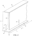
Figure 3 is a perspective view of part of a shear web comprising a web disposed between upper and lower mounting flanges according to an embodiment of the present invention; -
Figure 4 is a plan view of an outer surface of the lower mounting flange of the shear web; -
Figures 5 to 8 are schematic cross-sectional views of the lower mounting flange of the shear web taken along the line A-A inFigure 3 , with the shear web positioned against an inner surface of a blade shell; - Referring to
Figure 3 , this shows a first end of a longitudinally-extendingshear web 50 according to an embodiment of the present invention. In this example, theshear web 50 is approximately 80 metres in length (L) and varies in height (H) along its length, with a maximum height at one end of about 4.5 metres. Theshear web 50 is substantially I-shaped in cross section and comprises a substantiallyvertical web 52 disposed between upper andlower mounting flanges mounting flanges web 52 in this example, i.e. substantially horizontal. - The
lower mounting flange 56 comprises aninner surface 58 and anouter surface 60. The terms 'inner' and 'outer' are relative to a central longitudinal axis of a wind turbine blade in which theshear web 50 is affixed in use (e.g. the central longitudinal axis (C) of theblade 10 inFigure 1 , which extends perpendicular to the page inFigure 1 ). - The
outer surface 60 of thelower mounting flange 56 is shown in plan view inFigure 4 . Aseal 66 is provided on theouter surface 60 of thelower mounting flange 56. Theseal 66 is a vacuum-tight seal and in this example is made from butyl-rubber. The seal is arranged around the periphery of the mounting flange. In other words, theseal 66 is arranged in a rectangle such that arectangular cavity 70 is defined within theseal 66.Vacuum ports 62 are provided on the mountingflange 56 and are in fluid communication with thecavity 70. - When the lower mounting
flange 56 of theshear web 50 is positioned against a surface (seeFigure 5 ), such as the inner surface 74 of a blade shell 75, theseal 66 defines a substantiallyrectangular cavity 76 between the lower mountingflange 56 and the surface 74. Thecavity 76 is located directly below theweb portion 52 of theshear web 50. Thevacuum ports 62 are in fluid communication with thecavity 76 in use. - An effective vacuum is applied to the
cavity 76 via thevacuum ports 62. In use, a set of vacuum lines are connected to vacuum ports and to a vacuum pump so that air can be evacuated from thecavity 76. - As shown most clearly in
Figure 3 , thevacuum ports 62 project upwardly from theinner surface 58 of the lower mountingflange 56 for ease of access. - During the manufacture of a wind turbine blade, the
shear web 50 is bonded to an inner surface 74 of a blade shell as will now be described. - Referring to
Figure 6 , a bead of adhesive 80 (which in this example is epoxy adhesive) is applied to the inner surface 74 of the blade shell 75. The bead of adhesive 80 extends in the longitudinal direction L. It is important to note that the bead of adhesive 80 is applied to the blade shell 75 before theshear web 50 is brought into contact with the blade shell. - In
Figure 7 it can be seen that theshear web 50 has been brought into contact with the blade shell 75 thus forming thecavity 76. The adhesive 80 is now located within thecavity 76. Theshear web 50 is initially positioned against the inner surface 74 of the blade shell 75 and arranged such that theweb 52 is located over apredefined bonding region 100 defined on the blade shell 75, i.e. the region where a bondline between theshear web 50 and the blade shell 75 is to be created. When positioned against the inner surface 74 of the blade shell 75, theshear web 50 is supported against the surface 74 by theseal 66. In this position theseal 66 is compressed slightly under the weight of theshear web 50. - As the
shear web 50 is placed onto the blade shell, the adhesive 80 touches theouter surface 60 of the lower mountingflange 56 such that the adhesive is displaced outwards toward theseal 66. - With the
shear web 50 in position against the surface 74 of the blade shell 75, the vacuum pump is turned on. The vacuum pump draws air out of thecavity 76 through thevacuum ports 62. The removal of air from thecavity 76 pulls the lower mountingflange 56 toward the blade shell 75 which compresses theseal 66 as shown inFigure 8 . A membrane (or other suitable device) is located at thevacuum ports 62 such that only air is evacuated from the cavity, rather than the adhesive itself. - The
lower mounting flange 56 is sucked towards the surface 74 such that the adhesive 80 is forced to fill thecavity 76. - The adhesive 80 is then left to cure, i.e. harden, which results in the lower mounting
flange 56 forming a strong bond to the inner surface 74 of the blade shell 75. - As the adhesive is contained within the
cavity 76, wastage of adhesive caused by squeeze out, i.e. adhesive spew, is eliminated. This reduces the overall amount of adhesive required in the bondline and hence reduces the overall weight of the completed blade and the materials cost of the adhesive. The dimensions of the resulting bondline between theshear web 50 and the blade shell 75 are advantageously well defined, i.e. they are defined by the dimensions of thecavity 76. The dimensions of thecavity 76 are predefined by the shape of the region bound by theseal 66. The use of a vacuum provides a constant pressure on the adhesive 80 via the lower mountingflange 56. Accordingly, the invention provides a repeatable process for creating consistently well-defined bondlines. - In an example, the
seal 66 is integrated with the mountingflange 56 of theshear web 50 prior to positioning the shear web against the blade shell 75. This means that the seal is pre-attached to the shear web and that it is not necessary to place the seal and the shear web on the blade shell as separate elements. This reduces the process time of bonding the shear web to the blade shell. - Many modifications may be made to the above examples without departing from the scope of the present invention as defined in the accompanying claims.
- For example, whilst the above examples relate to the creation of a bond between the lower mounting
flange 56 of theshear web 50 and the blade shell, the bond could alternatively or additionally be created between the upper mountingflange 54 and the blade shell. If used for the upper mounting flange the adhesive could be applied to the upper mountingflange 56 rather than the blade shell - in this example the bead of adhesive is applied to the upper mounting flange before the blade shell is brought into contact with the shear web. - The process could also be used simultaneously along the upper and lower mounting
flanges shear web 50 to both the windward shell and the leeward shell simultaneously. - Whilst a
shear web 50 having an I-shaped cross section is described in the above examples, theshear web 50 may have a different shape in other examples. For example, theshear web 50 may be substantially C-shaped in cross-section or theweb 52 may have L-shaped flanges at each end. The mountingflanges web 52, and in other examples the mountingflanges web 52, for example more or less than ninety degrees. The angle of the mountingflanges web 52 will depend on the local contour of the blade shell at which theshear web 50 is to be fixed, i.e. in a chordwise direction of the blade shell. - Whilst the
vacuum ports 62 in the above example are provided in the mountingflange 56 of theshear web 50, the ports may alternatively be provided in other suitable positions. For example,vacuum ports 62 may be provided in theseal 66 or in the blade shell or other such surface to which theshear web 50 is bonded. - For the avoidance of doubt, relative terms such as 'upper' and 'lower' as used in the preceding description are used for convenience and refer to the orientation of features as shown in the figures. These terms are not intended to limit the scope of the invention.
Claims (6)
- A method of bonding a shear web (50) to a wind turbine blade shell (75), the shear web comprising a web (52) and a mounting flange (56) oriented transverse to the web, wherein the method comprises:providing a seal (66) around a periphery of the mounting flange;applying adhesive (80) to an inner surface (74) of the blade shell or to the mounting
flange (56);positioning the shear web (50) relative to the blade shell (75), after the step of applying adhesive (80), such that the mounting flange (56) is in mutually opposed relation with the inner surface (74) of the blade shell and such that the seal (66) defines a substantially enclosed cavity (76) between the mounting flange and the inner surface of the blade shell, the cavity containing the adhesive;evacuating air from the cavity (76) such that the mounting flange (56) and the blade shell (75) are forced together under the influence of a vacuum or partial vacuum in the enclosed cavity; andcuring the adhesive (80). - The method of claim 1, wherein the seal (66) is integrated with the mounting flange (56) of the shear web (50) prior to positioning the shear web against the blade shell (75).
- The method of claim 1 or claim 2, further comprising removing air from the cavity (76) through one or more vacuum ports (62) provided in fluid communication with the cavity.
- The method of Claim 3, wherein the vacuum ports (62) are provided in the mounting flange (56) of the shear web.
- A method of making a wind turbine blade comprising bonding a shear web (50) to an inner surface (74) of a wind turbine blade shell (75) according to the method of any preceding claim.
- The method of Claim 5, wherein the blade shell (75) is a first half shell of the wind turbine blade and the method further comprises bonding a second half shell to the first half shell.
Applications Claiming Priority (2)
| Application Number | Priority Date | Filing Date | Title |
|---|---|---|---|
| DKPA201570519 | 2015-08-11 | ||
| PCT/DK2016/050269 WO2017025103A1 (en) | 2015-08-11 | 2016-08-09 | Wind turbine blade bondlines |
Publications (2)
| Publication Number | Publication Date |
|---|---|
| EP3328618A1 EP3328618A1 (en) | 2018-06-06 |
| EP3328618B1 true EP3328618B1 (en) | 2021-03-31 |
Family
ID=56740737
Family Applications (1)
| Application Number | Title | Priority Date | Filing Date |
|---|---|---|---|
| EP16754184.6A Active EP3328618B1 (en) | 2015-08-11 | 2016-08-09 | Wind turbine blade bondlines |
Country Status (2)
| Country | Link |
|---|---|
| EP (1) | EP3328618B1 (en) |
| WO (1) | WO2017025103A1 (en) |
Families Citing this family (1)
| Publication number | Priority date | Publication date | Assignee | Title |
|---|---|---|---|---|
| FR3075081B1 (en) * | 2017-12-19 | 2021-01-08 | Safran Aircraft Engines | METHOD AND TOOLS FOR MANUFACTURING A HOLLOW VANE |
Family Cites Families (2)
| Publication number | Priority date | Publication date | Assignee | Title |
|---|---|---|---|---|
| US7645406B2 (en) * | 2005-04-21 | 2010-01-12 | The Boeing Company | Adhesive injection process for Pi-joint assemblies |
| PL2931498T3 (en) * | 2012-12-03 | 2020-03-31 | Lm Wp Patent Holding A/S | Method of manufacturing a wind turbine blade |
-
2016
- 2016-08-09 WO PCT/DK2016/050269 patent/WO2017025103A1/en active Application Filing
- 2016-08-09 EP EP16754184.6A patent/EP3328618B1/en active Active
Non-Patent Citations (1)
| Title |
|---|
| None * |
Also Published As
| Publication number | Publication date |
|---|---|
| WO2017025103A1 (en) | 2017-02-16 |
| EP3328618A1 (en) | 2018-06-06 |
Similar Documents
| Publication | Publication Date | Title |
|---|---|---|
| US11041477B2 (en) | Reinforcing structure for a wind turbine blade | |
| EP3188895B1 (en) | Improvements relating to wind turbine blade manufacture | |
| EP3475068B1 (en) | Manufacture of a wind turbine blade | |
| EP2922690B1 (en) | Wind turbine blades and method of manufacturing the same | |
| EP3212387B1 (en) | Manufacture of i-shaped shear web, method and apparatus | |
| EP3161307B1 (en) | Improvements relating to wind turbine blade manufacture | |
| US20090146433A1 (en) | Method and apparatus for fabricating wind turbine components | |
| EP3191708B1 (en) | Improvements relating to wind turbine blade manufacture | |
| EP3380293B1 (en) | Method and apparatus for manufacturing a wind turbine blade body | |
| CA2958507C (en) | A reinforced wind turbine blade component | |
| EP3328618B1 (en) | Wind turbine blade bondlines | |
| GB2535697A (en) | Improvements relating to wind turbine blade manufacture | |
| EP3723972B1 (en) | A system and method for manufacturing a reinforced wind turbine blade | |
| DK201470750A1 (en) | Monitoring bondlines in wind turbine blade manufacture | |
| DK201870879A1 (en) | Method and Apparatus for Making a Wind Turbine Blade |
Legal Events
| Date | Code | Title | Description |
|---|---|---|---|
| STAA | Information on the status of an ep patent application or granted ep patent |
Free format text: STATUS: THE INTERNATIONAL PUBLICATION HAS BEEN MADE |
|
| PUAI | Public reference made under article 153(3) epc to a published international application that has entered the european phase |
Free format text: ORIGINAL CODE: 0009012 |
|
| STAA | Information on the status of an ep patent application or granted ep patent |
Free format text: STATUS: REQUEST FOR EXAMINATION WAS MADE |
|
| 17P | Request for examination filed |
Effective date: 20180208 |
|
| AK | Designated contracting states |
Kind code of ref document: A1 Designated state(s): AL AT BE BG CH CY CZ DE DK EE ES FI FR GB GR HR HU IE IS IT LI LT LU LV MC MK MT NL NO PL PT RO RS SE SI SK SM TR |
|
| AX | Request for extension of the european patent |
Extension state: BA ME |
|
| DAV | Request for validation of the european patent (deleted) | ||
| DAX | Request for extension of the european patent (deleted) | ||
| GRAP | Despatch of communication of intention to grant a patent |
Free format text: ORIGINAL CODE: EPIDOSNIGR1 |
|
| STAA | Information on the status of an ep patent application or granted ep patent |
Free format text: STATUS: GRANT OF PATENT IS INTENDED |
|
| RIC1 | Information provided on ipc code assigned before grant |
Ipc: B29L 31/08 20060101ALI20201007BHEP Ipc: F03D 1/06 20060101ALI20201007BHEP Ipc: B29C 65/78 20060101ALI20201007BHEP Ipc: B29C 65/48 20060101AFI20201007BHEP Ipc: B29C 65/00 20060101ALI20201007BHEP |
|
| INTG | Intention to grant announced |
Effective date: 20201021 |
|
| GRAS | Grant fee paid |
Free format text: ORIGINAL CODE: EPIDOSNIGR3 |
|
| GRAA | (expected) grant |
Free format text: ORIGINAL CODE: 0009210 |
|
| STAA | Information on the status of an ep patent application or granted ep patent |
Free format text: STATUS: THE PATENT HAS BEEN GRANTED |
|
| AK | Designated contracting states |
Kind code of ref document: B1 Designated state(s): AL AT BE BG CH CY CZ DE DK EE ES FI FR GB GR HR HU IE IS IT LI LT LU LV MC MK MT NL NO PL PT RO RS SE SI SK SM TR |
|
| REG | Reference to a national code |
Ref country code: GB Ref legal event code: FG4D Ref country code: CH Ref legal event code: EP |
|
| REG | Reference to a national code |
Ref country code: AT Ref legal event code: REF Ref document number: 1376454 Country of ref document: AT Kind code of ref document: T Effective date: 20210415 |
|
| REG | Reference to a national code |
Ref country code: DE Ref legal event code: R096 Ref document number: 602016055265 Country of ref document: DE |
|
| REG | Reference to a national code |
Ref country code: IE Ref legal event code: FG4D |
|
| REG | Reference to a national code |
Ref country code: LT Ref legal event code: MG9D |
|
| PG25 | Lapsed in a contracting state [announced via postgrant information from national office to epo] |
Ref country code: NO Free format text: LAPSE BECAUSE OF FAILURE TO SUBMIT A TRANSLATION OF THE DESCRIPTION OR TO PAY THE FEE WITHIN THE PRESCRIBED TIME-LIMIT Effective date: 20210630 Ref country code: HR Free format text: LAPSE BECAUSE OF FAILURE TO SUBMIT A TRANSLATION OF THE DESCRIPTION OR TO PAY THE FEE WITHIN THE PRESCRIBED TIME-LIMIT Effective date: 20210331 Ref country code: FI Free format text: LAPSE BECAUSE OF FAILURE TO SUBMIT A TRANSLATION OF THE DESCRIPTION OR TO PAY THE FEE WITHIN THE PRESCRIBED TIME-LIMIT Effective date: 20210331 Ref country code: BG Free format text: LAPSE BECAUSE OF FAILURE TO SUBMIT A TRANSLATION OF THE DESCRIPTION OR TO PAY THE FEE WITHIN THE PRESCRIBED TIME-LIMIT Effective date: 20210630 |
|
| PG25 | Lapsed in a contracting state [announced via postgrant information from national office to epo] |
Ref country code: LV Free format text: LAPSE BECAUSE OF FAILURE TO SUBMIT A TRANSLATION OF THE DESCRIPTION OR TO PAY THE FEE WITHIN THE PRESCRIBED TIME-LIMIT Effective date: 20210331 Ref country code: RS Free format text: LAPSE BECAUSE OF FAILURE TO SUBMIT A TRANSLATION OF THE DESCRIPTION OR TO PAY THE FEE WITHIN THE PRESCRIBED TIME-LIMIT Effective date: 20210331 Ref country code: SE Free format text: LAPSE BECAUSE OF FAILURE TO SUBMIT A TRANSLATION OF THE DESCRIPTION OR TO PAY THE FEE WITHIN THE PRESCRIBED TIME-LIMIT Effective date: 20210331 |
|
| REG | Reference to a national code |
Ref country code: NL Ref legal event code: MP Effective date: 20210331 |
|
| REG | Reference to a national code |
Ref country code: AT Ref legal event code: MK05 Ref document number: 1376454 Country of ref document: AT Kind code of ref document: T Effective date: 20210331 |
|
| PG25 | Lapsed in a contracting state [announced via postgrant information from national office to epo] |
Ref country code: EE Free format text: LAPSE BECAUSE OF FAILURE TO SUBMIT A TRANSLATION OF THE DESCRIPTION OR TO PAY THE FEE WITHIN THE PRESCRIBED TIME-LIMIT Effective date: 20210331 Ref country code: CZ Free format text: LAPSE BECAUSE OF FAILURE TO SUBMIT A TRANSLATION OF THE DESCRIPTION OR TO PAY THE FEE WITHIN THE PRESCRIBED TIME-LIMIT Effective date: 20210331 Ref country code: LT Free format text: LAPSE BECAUSE OF FAILURE TO SUBMIT A TRANSLATION OF THE DESCRIPTION OR TO PAY THE FEE WITHIN THE PRESCRIBED TIME-LIMIT Effective date: 20210331 Ref country code: NL Free format text: LAPSE BECAUSE OF FAILURE TO SUBMIT A TRANSLATION OF THE DESCRIPTION OR TO PAY THE FEE WITHIN THE PRESCRIBED TIME-LIMIT Effective date: 20210331 Ref country code: AT Free format text: LAPSE BECAUSE OF FAILURE TO SUBMIT A TRANSLATION OF THE DESCRIPTION OR TO PAY THE FEE WITHIN THE PRESCRIBED TIME-LIMIT Effective date: 20210331 Ref country code: SM Free format text: LAPSE BECAUSE OF FAILURE TO SUBMIT A TRANSLATION OF THE DESCRIPTION OR TO PAY THE FEE WITHIN THE PRESCRIBED TIME-LIMIT Effective date: 20210331 |
|
| PG25 | Lapsed in a contracting state [announced via postgrant information from national office to epo] |
Ref country code: PL Free format text: LAPSE BECAUSE OF FAILURE TO SUBMIT A TRANSLATION OF THE DESCRIPTION OR TO PAY THE FEE WITHIN THE PRESCRIBED TIME-LIMIT Effective date: 20210331 Ref country code: PT Free format text: LAPSE BECAUSE OF FAILURE TO SUBMIT A TRANSLATION OF THE DESCRIPTION OR TO PAY THE FEE WITHIN THE PRESCRIBED TIME-LIMIT Effective date: 20210802 Ref country code: SK Free format text: LAPSE BECAUSE OF FAILURE TO SUBMIT A TRANSLATION OF THE DESCRIPTION OR TO PAY THE FEE WITHIN THE PRESCRIBED TIME-LIMIT Effective date: 20210331 Ref country code: RO Free format text: LAPSE BECAUSE OF FAILURE TO SUBMIT A TRANSLATION OF THE DESCRIPTION OR TO PAY THE FEE WITHIN THE PRESCRIBED TIME-LIMIT Effective date: 20210331 Ref country code: IS Free format text: LAPSE BECAUSE OF FAILURE TO SUBMIT A TRANSLATION OF THE DESCRIPTION OR TO PAY THE FEE WITHIN THE PRESCRIBED TIME-LIMIT Effective date: 20210731 |
|
| REG | Reference to a national code |
Ref country code: DE Ref legal event code: R097 Ref document number: 602016055265 Country of ref document: DE |
|
| PG25 | Lapsed in a contracting state [announced via postgrant information from national office to epo] |
Ref country code: AL Free format text: LAPSE BECAUSE OF FAILURE TO SUBMIT A TRANSLATION OF THE DESCRIPTION OR TO PAY THE FEE WITHIN THE PRESCRIBED TIME-LIMIT Effective date: 20210331 Ref country code: ES Free format text: LAPSE BECAUSE OF FAILURE TO SUBMIT A TRANSLATION OF THE DESCRIPTION OR TO PAY THE FEE WITHIN THE PRESCRIBED TIME-LIMIT Effective date: 20210331 Ref country code: DK Free format text: LAPSE BECAUSE OF FAILURE TO SUBMIT A TRANSLATION OF THE DESCRIPTION OR TO PAY THE FEE WITHIN THE PRESCRIBED TIME-LIMIT Effective date: 20210331 |
|
| PLBE | No opposition filed within time limit |
Free format text: ORIGINAL CODE: 0009261 |
|
| STAA | Information on the status of an ep patent application or granted ep patent |
Free format text: STATUS: NO OPPOSITION FILED WITHIN TIME LIMIT |
|
| 26N | No opposition filed |
Effective date: 20220104 |
|
| REG | Reference to a national code |
Ref country code: CH Ref legal event code: PL |
|
| PG25 | Lapsed in a contracting state [announced via postgrant information from national office to epo] |
Ref country code: MC Free format text: LAPSE BECAUSE OF FAILURE TO SUBMIT A TRANSLATION OF THE DESCRIPTION OR TO PAY THE FEE WITHIN THE PRESCRIBED TIME-LIMIT Effective date: 20210331 |
|
| REG | Reference to a national code |
Ref country code: BE Ref legal event code: MM Effective date: 20210831 |
|
| PG25 | Lapsed in a contracting state [announced via postgrant information from national office to epo] |
Ref country code: LI Free format text: LAPSE BECAUSE OF NON-PAYMENT OF DUE FEES Effective date: 20210831 Ref country code: CH Free format text: LAPSE BECAUSE OF NON-PAYMENT OF DUE FEES Effective date: 20210831 |
|
| PG25 | Lapsed in a contracting state [announced via postgrant information from national office to epo] |
Ref country code: IS Free format text: LAPSE BECAUSE OF FAILURE TO SUBMIT A TRANSLATION OF THE DESCRIPTION OR TO PAY THE FEE WITHIN THE PRESCRIBED TIME-LIMIT Effective date: 20210731 Ref country code: LU Free format text: LAPSE BECAUSE OF NON-PAYMENT OF DUE FEES Effective date: 20210809 |
|
| PG25 | Lapsed in a contracting state [announced via postgrant information from national office to epo] |
Ref country code: IT Free format text: LAPSE BECAUSE OF FAILURE TO SUBMIT A TRANSLATION OF THE DESCRIPTION OR TO PAY THE FEE WITHIN THE PRESCRIBED TIME-LIMIT Effective date: 20210331 Ref country code: IE Free format text: LAPSE BECAUSE OF NON-PAYMENT OF DUE FEES Effective date: 20210809 Ref country code: BE Free format text: LAPSE BECAUSE OF NON-PAYMENT OF DUE FEES Effective date: 20210831 |
|
| PG25 | Lapsed in a contracting state [announced via postgrant information from national office to epo] |
Ref country code: HU Free format text: LAPSE BECAUSE OF FAILURE TO SUBMIT A TRANSLATION OF THE DESCRIPTION OR TO PAY THE FEE WITHIN THE PRESCRIBED TIME-LIMIT; INVALID AB INITIO Effective date: 20160809 |
|
| P01 | Opt-out of the competence of the unified patent court (upc) registered |
Effective date: 20230521 |
|
| PG25 | Lapsed in a contracting state [announced via postgrant information from national office to epo] |
Ref country code: CY Free format text: LAPSE BECAUSE OF FAILURE TO SUBMIT A TRANSLATION OF THE DESCRIPTION OR TO PAY THE FEE WITHIN THE PRESCRIBED TIME-LIMIT Effective date: 20210331 |
|
| PG25 | Lapsed in a contracting state [announced via postgrant information from national office to epo] |
Ref country code: GR Free format text: LAPSE BECAUSE OF FAILURE TO SUBMIT A TRANSLATION OF THE DESCRIPTION OR TO PAY THE FEE WITHIN THE PRESCRIBED TIME-LIMIT Effective date: 20210331 |
|
| PGFP | Annual fee paid to national office [announced via postgrant information from national office to epo] |
Ref country code: GB Payment date: 20230822 Year of fee payment: 8 |
|
| PGFP | Annual fee paid to national office [announced via postgrant information from national office to epo] |
Ref country code: FR Payment date: 20230824 Year of fee payment: 8 Ref country code: DE Payment date: 20230828 Year of fee payment: 8 |