EP3328560B1 - Device for the dry-cleaning of an additive manufacturing plate - Google Patents
Device for the dry-cleaning of an additive manufacturing plate Download PDFInfo
- Publication number
- EP3328560B1 EP3328560B1 EP16745118.6A EP16745118A EP3328560B1 EP 3328560 B1 EP3328560 B1 EP 3328560B1 EP 16745118 A EP16745118 A EP 16745118A EP 3328560 B1 EP3328560 B1 EP 3328560B1
- Authority
- EP
- European Patent Office
- Prior art keywords
- cleaning
- enclosure
- plate
- dry
- cleaning device
- Prior art date
- Legal status (The legal status is an assumption and is not a legal conclusion. Google has not performed a legal analysis and makes no representation as to the accuracy of the status listed.)
- Active
Links
- 238000005108 dry cleaning Methods 0.000 title claims description 95
- 238000004519 manufacturing process Methods 0.000 title claims description 70
- 239000000654 additive Substances 0.000 title claims description 44
- 230000000996 additive effect Effects 0.000 title claims description 44
- 238000004140 cleaning Methods 0.000 claims description 114
- 239000000843 powder Substances 0.000 claims description 94
- 230000035939 shock Effects 0.000 claims description 31
- 230000000295 complement effect Effects 0.000 claims description 2
- 238000009434 installation Methods 0.000 description 41
- 230000005484 gravity Effects 0.000 description 11
- 239000007788 liquid Substances 0.000 description 10
- 238000000034 method Methods 0.000 description 10
- 239000003595 mist Substances 0.000 description 10
- 238000003860 storage Methods 0.000 description 9
- 230000000694 effects Effects 0.000 description 6
- 238000005406 washing Methods 0.000 description 6
- 230000001681 protective effect Effects 0.000 description 5
- 238000001035 drying Methods 0.000 description 4
- 238000011084 recovery Methods 0.000 description 4
- 239000007864 aqueous solution Substances 0.000 description 3
- 238000000151 deposition Methods 0.000 description 3
- 238000007596 consolidation process Methods 0.000 description 2
- 230000008021 deposition Effects 0.000 description 2
- 230000010355 oscillation Effects 0.000 description 2
- 239000002245 particle Substances 0.000 description 2
- 230000002093 peripheral effect Effects 0.000 description 2
- 230000001988 toxicity Effects 0.000 description 2
- 231100000419 toxicity Toxicity 0.000 description 2
- 238000011282 treatment Methods 0.000 description 2
- 240000008042 Zea mays Species 0.000 description 1
- 230000001680 brushing effect Effects 0.000 description 1
- 231100000481 chemical toxicant Toxicity 0.000 description 1
- 150000001875 compounds Chemical class 0.000 description 1
- 230000006835 compression Effects 0.000 description 1
- 238000007906 compression Methods 0.000 description 1
- 238000005202 decontamination Methods 0.000 description 1
- 230000003588 decontaminative effect Effects 0.000 description 1
- 230000005670 electromagnetic radiation Effects 0.000 description 1
- 238000010894 electron beam technology Methods 0.000 description 1
- 238000005265 energy consumption Methods 0.000 description 1
- 239000012530 fluid Substances 0.000 description 1
- 230000004927 fusion Effects 0.000 description 1
- 230000014759 maintenance of location Effects 0.000 description 1
- 230000000149 penetrating effect Effects 0.000 description 1
- 230000001737 promoting effect Effects 0.000 description 1
- 230000001902 propagating effect Effects 0.000 description 1
- 230000000284 resting effect Effects 0.000 description 1
- 238000007789 sealing Methods 0.000 description 1
- 238000007873 sieving Methods 0.000 description 1
- 238000005245 sintering Methods 0.000 description 1
- 239000003440 toxic substance Substances 0.000 description 1
- 230000007306 turnover Effects 0.000 description 1
- 238000011144 upstream manufacturing Methods 0.000 description 1
Images


Classifications
-
- B—PERFORMING OPERATIONS; TRANSPORTING
- B29—WORKING OF PLASTICS; WORKING OF SUBSTANCES IN A PLASTIC STATE IN GENERAL
- B29C—SHAPING OR JOINING OF PLASTICS; SHAPING OF MATERIAL IN A PLASTIC STATE, NOT OTHERWISE PROVIDED FOR; AFTER-TREATMENT OF THE SHAPED PRODUCTS, e.g. REPAIRING
- B29C64/00—Additive manufacturing, i.e. manufacturing of three-dimensional [3D] objects by additive deposition, additive agglomeration or additive layering, e.g. by 3D printing, stereolithography or selective laser sintering
- B29C64/30—Auxiliary operations or equipment
- B29C64/35—Cleaning
-
- B—PERFORMING OPERATIONS; TRANSPORTING
- B08—CLEANING
- B08B—CLEANING IN GENERAL; PREVENTION OF FOULING IN GENERAL
- B08B3/00—Cleaning by methods involving the use or presence of liquid or steam
- B08B3/04—Cleaning involving contact with liquid
- B08B3/10—Cleaning involving contact with liquid with additional treatment of the liquid or of the object being cleaned, e.g. by heat, by electricity or by vibration
- B08B3/12—Cleaning involving contact with liquid with additional treatment of the liquid or of the object being cleaned, e.g. by heat, by electricity or by vibration by sonic or ultrasonic vibrations
- B08B3/123—Cleaning travelling work, e.g. webs, articles on a conveyor
-
- B—PERFORMING OPERATIONS; TRANSPORTING
- B08—CLEANING
- B08B—CLEANING IN GENERAL; PREVENTION OF FOULING IN GENERAL
- B08B5/00—Cleaning by methods involving the use of air flow or gas flow
- B08B5/04—Cleaning by suction, with or without auxiliary action
-
- B—PERFORMING OPERATIONS; TRANSPORTING
- B08—CLEANING
- B08B—CLEANING IN GENERAL; PREVENTION OF FOULING IN GENERAL
- B08B5/00—Cleaning by methods involving the use of air flow or gas flow
- B08B5/04—Cleaning by suction, with or without auxiliary action
- B08B5/043—Cleaning travelling work
- B08B5/046—Cleaning moving webs
-
- B—PERFORMING OPERATIONS; TRANSPORTING
- B08—CLEANING
- B08B—CLEANING IN GENERAL; PREVENTION OF FOULING IN GENERAL
- B08B7/00—Cleaning by methods not provided for in a single other subclass or a single group in this subclass
- B08B7/02—Cleaning by methods not provided for in a single other subclass or a single group in this subclass by distortion, beating, or vibration of the surface to be cleaned
- B08B7/026—Using sound waves
- B08B7/028—Using ultrasounds
-
- B—PERFORMING OPERATIONS; TRANSPORTING
- B08—CLEANING
- B08B—CLEANING IN GENERAL; PREVENTION OF FOULING IN GENERAL
- B08B7/00—Cleaning by methods not provided for in a single other subclass or a single group in this subclass
- B08B7/04—Cleaning by methods not provided for in a single other subclass or a single group in this subclass by a combination of operations
-
- B—PERFORMING OPERATIONS; TRANSPORTING
- B29—WORKING OF PLASTICS; WORKING OF SUBSTANCES IN A PLASTIC STATE IN GENERAL
- B29C—SHAPING OR JOINING OF PLASTICS; SHAPING OF MATERIAL IN A PLASTIC STATE, NOT OTHERWISE PROVIDED FOR; AFTER-TREATMENT OF THE SHAPED PRODUCTS, e.g. REPAIRING
- B29C64/00—Additive manufacturing, i.e. manufacturing of three-dimensional [3D] objects by additive deposition, additive agglomeration or additive layering, e.g. by 3D printing, stereolithography or selective laser sintering
- B29C64/10—Processes of additive manufacturing
- B29C64/141—Processes of additive manufacturing using only solid materials
- B29C64/153—Processes of additive manufacturing using only solid materials using layers of powder being selectively joined, e.g. by selective laser sintering or melting
-
- B—PERFORMING OPERATIONS; TRANSPORTING
- B29—WORKING OF PLASTICS; WORKING OF SUBSTANCES IN A PLASTIC STATE IN GENERAL
- B29C—SHAPING OR JOINING OF PLASTICS; SHAPING OF MATERIAL IN A PLASTIC STATE, NOT OTHERWISE PROVIDED FOR; AFTER-TREATMENT OF THE SHAPED PRODUCTS, e.g. REPAIRING
- B29C64/00—Additive manufacturing, i.e. manufacturing of three-dimensional [3D] objects by additive deposition, additive agglomeration or additive layering, e.g. by 3D printing, stereolithography or selective laser sintering
- B29C64/20—Apparatus for additive manufacturing; Details thereof or accessories therefor
- B29C64/245—Platforms or substrates
-
- B—PERFORMING OPERATIONS; TRANSPORTING
- B29—WORKING OF PLASTICS; WORKING OF SUBSTANCES IN A PLASTIC STATE IN GENERAL
- B29C—SHAPING OR JOINING OF PLASTICS; SHAPING OF MATERIAL IN A PLASTIC STATE, NOT OTHERWISE PROVIDED FOR; AFTER-TREATMENT OF THE SHAPED PRODUCTS, e.g. REPAIRING
- B29C64/00—Additive manufacturing, i.e. manufacturing of three-dimensional [3D] objects by additive deposition, additive agglomeration or additive layering, e.g. by 3D printing, stereolithography or selective laser sintering
- B29C64/30—Auxiliary operations or equipment
- B29C64/357—Recycling
-
- B—PERFORMING OPERATIONS; TRANSPORTING
- B29—WORKING OF PLASTICS; WORKING OF SUBSTANCES IN A PLASTIC STATE IN GENERAL
- B29C—SHAPING OR JOINING OF PLASTICS; SHAPING OF MATERIAL IN A PLASTIC STATE, NOT OTHERWISE PROVIDED FOR; AFTER-TREATMENT OF THE SHAPED PRODUCTS, e.g. REPAIRING
- B29C64/00—Additive manufacturing, i.e. manufacturing of three-dimensional [3D] objects by additive deposition, additive agglomeration or additive layering, e.g. by 3D printing, stereolithography or selective laser sintering
- B29C64/30—Auxiliary operations or equipment
- B29C64/386—Data acquisition or data processing for additive manufacturing
- B29C64/393—Data acquisition or data processing for additive manufacturing for controlling or regulating additive manufacturing processes
-
- B—PERFORMING OPERATIONS; TRANSPORTING
- B29—WORKING OF PLASTICS; WORKING OF SUBSTANCES IN A PLASTIC STATE IN GENERAL
- B29C—SHAPING OR JOINING OF PLASTICS; SHAPING OF MATERIAL IN A PLASTIC STATE, NOT OTHERWISE PROVIDED FOR; AFTER-TREATMENT OF THE SHAPED PRODUCTS, e.g. REPAIRING
- B29C67/00—Shaping techniques not covered by groups B29C39/00 - B29C65/00, B29C70/00 or B29C73/00
- B29C67/0033—Shaping techniques not covered by groups B29C39/00 - B29C65/00, B29C70/00 or B29C73/00 by shock-waves
-
- B—PERFORMING OPERATIONS; TRANSPORTING
- B33—ADDITIVE MANUFACTURING TECHNOLOGY
- B33Y—ADDITIVE MANUFACTURING, i.e. MANUFACTURING OF THREE-DIMENSIONAL [3-D] OBJECTS BY ADDITIVE DEPOSITION, ADDITIVE AGGLOMERATION OR ADDITIVE LAYERING, e.g. BY 3-D PRINTING, STEREOLITHOGRAPHY OR SELECTIVE LASER SINTERING
- B33Y40/00—Auxiliary operations or equipment, e.g. for material handling
- B33Y40/20—Post-treatment, e.g. curing, coating or polishing
-
- B—PERFORMING OPERATIONS; TRANSPORTING
- B33—ADDITIVE MANUFACTURING TECHNOLOGY
- B33Y—ADDITIVE MANUFACTURING, i.e. MANUFACTURING OF THREE-DIMENSIONAL [3-D] OBJECTS BY ADDITIVE DEPOSITION, ADDITIVE AGGLOMERATION OR ADDITIVE LAYERING, e.g. BY 3-D PRINTING, STEREOLITHOGRAPHY OR SELECTIVE LASER SINTERING
- B33Y50/00—Data acquisition or data processing for additive manufacturing
- B33Y50/02—Data acquisition or data processing for additive manufacturing for controlling or regulating additive manufacturing processes
-
- B—PERFORMING OPERATIONS; TRANSPORTING
- B08—CLEANING
- B08B—CLEANING IN GENERAL; PREVENTION OF FOULING IN GENERAL
- B08B3/00—Cleaning by methods involving the use or presence of liquid or steam
- B08B3/04—Cleaning involving contact with liquid
- B08B3/10—Cleaning involving contact with liquid with additional treatment of the liquid or of the object being cleaned, e.g. by heat, by electricity or by vibration
- B08B3/12—Cleaning involving contact with liquid with additional treatment of the liquid or of the object being cleaned, e.g. by heat, by electricity or by vibration by sonic or ultrasonic vibrations
-
- B—PERFORMING OPERATIONS; TRANSPORTING
- B29—WORKING OF PLASTICS; WORKING OF SUBSTANCES IN A PLASTIC STATE IN GENERAL
- B29K—INDEXING SCHEME ASSOCIATED WITH SUBCLASSES B29B, B29C OR B29D, RELATING TO MOULDING MATERIALS OR TO MATERIALS FOR MOULDS, REINFORCEMENTS, FILLERS OR PREFORMED PARTS, e.g. INSERTS
- B29K2105/00—Condition, form or state of moulded material or of the material to be shaped
- B29K2105/25—Solid
- B29K2105/251—Particles, powder or granules
-
- Y—GENERAL TAGGING OF NEW TECHNOLOGICAL DEVELOPMENTS; GENERAL TAGGING OF CROSS-SECTIONAL TECHNOLOGIES SPANNING OVER SEVERAL SECTIONS OF THE IPC; TECHNICAL SUBJECTS COVERED BY FORMER USPC CROSS-REFERENCE ART COLLECTIONS [XRACs] AND DIGESTS
- Y02—TECHNOLOGIES OR APPLICATIONS FOR MITIGATION OR ADAPTATION AGAINST CLIMATE CHANGE
- Y02P—CLIMATE CHANGE MITIGATION TECHNOLOGIES IN THE PRODUCTION OR PROCESSING OF GOODS
- Y02P10/00—Technologies related to metal processing
- Y02P10/25—Process efficiency
Definitions
- the invention lies in the field of powder-based additive manufacturing by sintering or fusion of the grains of this powder using an electromagnetic radiation energy beam, such as for example a laser beam, and/or a particle beam, such as an electron beam.
- an electromagnetic radiation energy beam such as for example a laser beam
- a particle beam such as an electron beam.
- the invention relates to the cleaning of additive manufacturing trays and parts manufactured on these trays.
- a first layer of powder is deposited on an additive manufacturing plate mounted to slide inside an enclosure surrounding the manufacturing. Then, this first layer of powder is consolidated according to a predetermined pattern using one of the aforementioned energy beams. Then, the manufacturing platform is lowered into its enclosure so as to allow the deposition and consolidation of a second layer of powder. Finally, the stages of lowering the plate then depositing and consolidating layers of powder follow one another until the deposit and consolidation of the last layer of powder useful for the manufacture of the parts to be produced.
- the manufactured part or parts find themselves embedded in the middle of a large quantity of unconsolidated powder which must be evacuated.
- the manufacturing plate is extracted from the machine, with or without its enclosure, and an operator manually releases the grains of powder using tools such as a brush and a compressed air blower or a vacuum cleaner.
- this first cleaning method is not easily compatible with an industrial application.
- this manual cleaning can be dangerous for the operator because the powders used in additive manufacturing generally contain toxic chemical compounds that can be inhaled by operators despite their protective equipment.
- the document WO 2015/071184 A1 describes a device for dry cleaning an additive manufacturing plate according to the preamble of claim 1.
- the additive manufacturing machine described in the European patent EP1793979 is equipped with means allowing an operator to handle and clean the parts manufactured in the manufacturing enclosure of the machine.
- these means comprise openings made in a wall of the manufacturing enclosure, a robot arm installed in the manufacturing enclosure, and a suction pipe that can be manipulated in this manufacturing enclosure.
- the openings are provided with protective gloves allowing an operator to introduce his hands into the manufacturing enclosure to clean the manufactured parts using the suction pipe, and the operator can control the robot arm from outside the machine to easily move the heaviest parts.
- a cover provided with two openings facing each other is placed on the top of the container, and a source of compressed air is connected to the first opening while a tank is connected to the second opening.
- a source of compressed air is connected to the first opening while a tank is connected to the second opening.
- the top of the container is equipped with a flared neck comprising a spout allowing the unconsolidated powder to be evacuated when the container is tilted using appropriate means and the build plate rises gradually.
- the unconsolidated powder is advantageously evacuated by gravity to a reservoir. Then, the tank being equipped with a sieve for receiving the manufactured parts, vibrations are used to finish separating the grains of powder from the manufactured parts.
- this second embodiment of the cleaning device does not use a flow of compressed air liable to pollute the unconsolidated powder, it does not allow the manufactured parts to be perfectly cleaned either.
- the present invention aims to obviate at least one of the drawbacks of the devices described in the documents of the prior art, while making it possible to clean a manufacturing plate alone or with the parts which have been manufactured on this tray and which remain attached to this tray at the end of the additive manufacturing cycle.
- the subject of the invention is a device for the dry cleaning of an additive manufacturing plate made using powder, according to claim 1.
- the dry cleaning station comprises means capable of imposing vibrations on the plate to be cleaned and means capable of subjecting this plate to shocks.
- the clumps of powder likely to form in the cavities of the manufactured parts disintegrate, and thanks to the application of vibrations, the majority of the grains of unconsolidated powder are gradually brought to separate from the manufactured parts and the build plate by gravity dropping from the plate or from the manufactured parts.
- the dry cleaning device comprises a cleaning enclosure inside the confinement enclosure, this cleaning enclosure taking the form of a bell mounted on a base, this base comprising an opening for receiving a tray to be cleaned, and the receiving means making it possible to transport a tray from the entry lock to the opening of the base of the cleaning enclosure.
- the means capable of imposing vibrations and the means capable of causing shocks are supported by the base of the cleaning enclosure and provided next to the opening receiving the tray to be cleaned.
- the cleaning enclosure comprises internal means for conveying a tray between its opening and the means of the dry cleaning station.
- the cleaning enclosure is mounted to pivot about a horizontal axis, and preferably so as to be able to pivot by at least 180 ° inside the enclosure of the dry cleaning device.
- the dry cleaning device comprises an actuator making it possible to control the angle of rotation of the cleaning enclosure around its horizontal axis.
- the cleaning chamber is equipped with means for recovering the powder by suction.
- the means for recovering powder by suction are connected to the top of the bell of the cleaning.
- the bell comprises a powder suction orifice between its base and its top, this orifice being connected to means for recovering a mist of powder by suction and making it possible to suck up the grains of powder from the mist of powder that forms when the bell is turned over.
- the means for recovering a mist of powder by suction are also connected to the interior volume of the confinement enclosure of the device. dry cleaning.
- the present invention relates to the cleaning of trays 10 of additive manufacturing.
- An additive manufacturing platform 10 takes the form of a parallelepipedic support, generally metallic, and a few centimeters in height and several tens of centimeters in length and width in a plane P10.
- such a plate 10 is used as a manufacturing support for the parts to be manufactured inside the manufacturing chamber of an additive manufacturing machine.
- the tray is mounted inside a manufacturing enclosure surrounding the tray in this manufacturing chamber, and the tray is mounted movable in vertical translation in this manufacturing enclosure so as to be able to be lowered before each new deposition of a bed of unconsolidated powder.
- the plate 10 is preferably surrounded by a jacket 12 acting as a manufacturing enclosure inside an additive manufacturing machine.
- the plate 10 and the sleeve 12 form a container 15.
- This container 15 is removably mounted inside an additive manufacturing machine in order to be able to be extracted from the chamber manufacturing of this machine with the manufactured parts 14 and the unconsolidated powder 16 which surrounds them.
- this container 15 makes it possible to facilitate the transport of the manufactured parts 14 and of the unconsolidated powder 16 from an additive manufacturing machine to another device present in an additive manufacturing workshop or to a cleaning installation such as that proposed by the present invention.
- a support 13 equips the plate 10.
- This support 13 takes the form of a frame on which a production plate 10 fits.
- this support 13 comprises bores 17.
- this support 13 is equipped with a peripheral seal 19 to prevent powder leaks when the plate 10 and its support 13 are moved in translation inside the sleeve 12.
- the main objectives of the present invention are to recover, without altering it, the large quantity of unconsolidated powder 16 which surrounds the parts 14 in a container 15 and to best rid the manufactured parts 14 and the additive manufacturing trays 10 of grains of unconsolidated powder.
- the invention provides an installation 20 for cleaning additive manufacturing trays as illustrated in picture 2 .
- This installation 20 comprises an entry lock 22 making it possible to receive a tray 10 to be cleaned from an additive manufacturing machine, suitable transport means 24 being provided for transporting the container 15, the manufactured parts 14 and the unconsolidated powder 16 in the best possible conditions from an additive manufacturing machine to the entrance lock 22 of the installation.
- the installation 20 also comprises an exit lock 26.
- the whole of the installation 20 being preferably confined in a protective enclosure 28 partially represented on the figures 2 to 4 , the outlet lock 26 is provided through a wall 30 of this enclosure 28.
- the exit lock 26 can also be used to supply the installation 20 with new and/or clean trays 10 from outside E of the installation, and the entry lock 22 can also be used to extract trays 10 clean from the cleaning installation 20 with a view to sending them to additive manufacturing machines via the means of transport 24.
- the installation 20 comprises a dry cleaning device 32 making it possible to clean a tray 10 using vibrations and shocks in a first confinement enclosure E32, a cleaning device wet 34 for cleaning a tray 10 using at least one liquid in a second containment enclosure E34, and at least one conveying device for transporting a tray 10 between the dry cleaning enclosure E32, the the E34 wet cleaning enclosure, and the installation's exit airlock 26.
- the dry cleaning device 32 aims to recover a maximum quantity of unconsolidated powder without altering it in order to be able to reuse this powder as quickly as possible, without prior drying treatment but only with sieving aimed at controlling the particle size. of the powder thus recycled.
- the wet cleaning device 34 aims to perfectly clean the manufactured parts 14 and the manufacturing plates 10 by removing all the grains of powder unconsolidated that may stick to parts and trays after dry cleaning.
- the wet cleaning device 34 comprises in its enclosure E34 at least one washing station 38 of a tray 10 with a cleaning liquid and at least one rinsing station 40 of a plate 10 with a rinsing liquid.
- the washing station 38 takes the form of a tank filled with cleaning liquid and equipped with means, such as a transducer, making it possible to emit ultrasonic waves of very high frequencies, preferably 20 kHz and possibly 45 kHz , in this cleaning fluid.
- the ultrasonic waves generate by a phenomenon of cavitation microscopic bubbles which implode under the effect of these same waves, and these implosions cause turbulence in the cleaning liquid making it possible to detach the last grains of powder still stuck to the manufactured parts 14 and to their manufacturing plate 10.
- the microscopic size of the bubbles allows them to penetrate into the smallest cavities of the manufactured parts 14.
- the cleaning liquid is an aqueous solution and the rinsing liquid is also an aqueous solution.
- the wet cleaning device 34 may comprise in its enclosure E34 a pre-washing station 42, obviously located upstream of the washing station 38.
- This prewash station 42 can take the form of a tank filled with prewash liquid and the prewash liquid is preferably an aqueous solution.
- the rinsing station 40 can also act as a drying station and comprise means for drying the cleaned trays and the manufactured parts 14, these drying means taking for example the form of a tank equipped with a hot air blower. .
- the wet cleaning device 34 comprises in its enclosure E34 conveying means (not shown) making it possible to convey in an automated manner the trays 10 to be cleaned and the manufactured parts 14 attached to these trays 10 between the various prewash 42, wash 38 and rinse 40 stations.
- the wet cleaning device 34 may comprise a single working chamber in which the trays 10 can be pre-washed, washed and optionally dried, and different storage chambers for storing the trays 10 before, between and/or after these different stages.
- the conveying means of the wet cleaning device 34 also make it possible to convey new and/or clean trays 10 through the enclosure E34 of the wet cleaning device 34, without passing through the various washing and rinsing stations.
- the installation comprises a first conveyor 44 for transporting trays 10 being cleaned from enclosure E32 of dry cleaning device 32 to enclosure E34 of wet cleaning device 34, and a second conveyor 46 for transport the cleaned trays 10 from the enclosure E34 of the wet cleaning device 34 to the exit lock 26 of the installation 20.
- the second conveyor 46 also makes it possible to transport trays 10 from the outlet lock 26 of the installation 20 to the enclosure E34 of the wet cleaning device 34
- the first conveyor 44 also makes it possible to transport trays 10 from the enclosure E34 of the wet cleaning device 34 to the enclosure E32 of the dry cleaning device 32.
- the installation 20 to supply an additive manufacturing workshop with new and/or clean trays 10, it may be provided to carry out a wet cleaning of these trays 10 in the wet cleaning device 34. This ensures the perfect cleaning and decontamination of these plates 10 before their use within an additive manufacturing machine, these plates 10 having been polluted outside E of the enclosure 28 of the installation 20 during manual handling or during storage without protection.
- the two conveyors 44,46 can be belt conveyors.
- the installation comprises a conveyor 36 making it possible to transport trays 10 from the enclosure E32 of the dry-cleaning device 32 to the exit lock 26 and vice versa from the exit lock 26 to enclosure E32 of dry cleaning device 32, at least one temporary storage area 48.50 for trays 10, and a manipulator arm 52 allowing a tray 10 to be moved between the dry cleaning device 32 , the wet cleaning device 34, the conveyor 36 and each temporary storage area 48.50.
- the conveyor 36 can be a belt conveyor
- each storage area 48,50 can take the form of an open storage device such as a shelf
- the manipulator arm 52 is an articulated arm at the end of which is mounted a device 54 for gripping a plate 10 such as for example a clamp.
- the manipulator arm 52 makes it possible, for example, to manage the stages of dry and wet cleaning of different trays 10 while the conveyor 36 is used to transfer clean trays 10 from the exit lock 26 to the dry cleaning device 32.
- two temporary storage areas 48 and 50 are provided in order to avoid storing clean trays 10 and trays 10 being cleaned in the same area.
- the manipulator arm 52 is rotatable around different horizontal and/or vertical axes in order to move each plate 10 as quickly as possible from one point to another.
- the manipulator arm 52 can be omitted and the conveyor 36 can be arranged so as to ensure only the transport of the trays 10 between the dry cleaning enclosure E32, the the E34 wet cleaning enclosure, and the installation's exit airlock 26.
- the invention proposes a device for dry cleaning 32 of a tray 10.
- this dry cleaning device 32 comprises a containment enclosure E32.
- this containment enclosure E32 comprises at least one entry lock 56, and in order to evacuate a cleaned tray 10, this containment enclosure E32 also comprises an outlet lock 58.
- the entry lock 56 of enclosure E32 of dry cleaning device 32 is also entry lock 22 of installation 20.
- the dry cleaning enclosure E32 being formed on the floor S by a front wall 60F, a rear wall 60R, a left side wall 62G, a right side wall 62D and a ceiling P, the entry lock 56 is provided through the rear wall 60R of the dry cleaning enclosure E32, and the exit lock 58 is provided through the right side wall 62D of the cleaning enclosure. dry clean E32.
- the dry cleaning device 32 comprises means 64 for receiving a tray 10 to be cleaned and a dry cleaning station 66 for this tray.
- the receiving means 64 make it possible to receive and transport a container 15 formed by a plate 10 to be cleaned, its support 13 and its sleeve 12.
- reception means 64 take for example the form of a chain conveyor 72.
- This chain conveyor 72 extends horizontally inside the dry cleaning enclosure E32, and in a longitudinal direction DL parallel to the planes side walls 62G, 62D of the enclosure E32 and perpendicular to the front 60F and rear 60R walls of this enclosure.
- this chain conveyor 72 makes it possible to transport a container 15, and therefore a tray 10 to be cleaned, from the entrance lock 56 of the enclosure E32 to the dry cleaning station 66.
- the dry cleaning device 32 comprises a second cleaning chamber 68 inside its first containment chamber E32.
- This second cleaning enclosure 68 takes the form of a bell 70 mounted on a base 74, and this base 74 comprises an opening 76 for receiving a plate 10 to be cleaned.
- the base 74 is substantially flat and rectangular, while the bell 70 has a pyramidal shape S70 extending around a central axis A70 perpendicular to the plane P74 of the base 74.
- the opening 76 is of shape and dimensions adjusted or adjustable to the shape and dimensions of the trays 10 to be cleaned.
- the pyramidal shape of the bell 70 around its central axis A70 facilitates the flow and the recovery of the unconsolidated powder 16 when this bell 70 is returned with a plate 10 to be cleaned.
- the bell 70 comprises a lower parallelepipedic part 70B around its central axis A70 and a pyramidal upper part 70H around its central axis A70, the lower part 70B parallelepipedal extending from the base 74, and the upper pyramidal part 70H extending between this lower part 70B and the top 78 of the bell 70.
- the bell can also take an entirely pyramidal, partially or entirely conical, partially or entirely frustoconical shape, or any other shape making it possible to form a funnel when the bell 70 is turned over.
- the top 78 of the bell 70 takes the form of a conduit 80 equipped with a valve 82 or any other flow control device.
- the invention provides for turning over the bell 70 and the plate 10 in order to recover the unconsolidated powder 16 surrounding the manufactured part(s) 14 in a container 15.
- the cleaning enclosure 68 to be in an initial position corresponding to an unturned position in which the bell 70 and its top 78 are located above the base 74.
- the plane P74 of the base 74 is substantially horizontal, as illustrated in the figure 6 and 7 .
- the reception means 64 make it possible to transport a container 15, and therefore a tray 10, from the entry lock 56 of the containment enclosure E32 to opposite the opening 76 of the base 74 of the cleaning enclosure 68 when this cleaning enclosure 68 is in its initial position.
- the dry cleaning device 32 comprises an elevator 84 making it possible to take a tray 10 to be cleaned from the reception means 64 to the opening 76.
- this elevator 84 makes it possible to move the plate 10 to be cleaned and its support 13 in vertical translation T1 inside the sleeve 12 of the container 15. More precisely, the sleeve 12 extending vertically in height around a central axis A12, the vertical translation T1 of the plate 10 and of its support 13 takes place parallel to the central axis A12 of the sleeve 12 and towards the edge upper 86 of shirt 12.
- the elevator 84 makes it possible to move the sleeve 12 in vertical translation T2 parallel to its central axis A12 and towards the base 74 of the cleaning enclosure 68
- the upper edge 86 of the jacket 12 is pressed against the lower edge 88 of the opening 76 of the base 74, which makes it possible to avoid the leakage of unconsolidated powder 16 when the plate 10 rises in the jacket 12 and that this powder is gradually transferred from the container 15 to the interior volume V68 of the cleaning chamber 68.
- the elevator 84 comprises for example a piston 90 guided in translation inside a body 92 and driven in translation by a motor 94 and a 96 worm screw.
- the elevator 84 comprises for example a plate 98 guided in translation around the rod 89 of the piston 90 and driven in translation by compression springs 100 resting on another plate 102 attached to body 92.
- the plates 98,102 and the springs 100 are sized and positioned relative to the body 92 and to the piston 90 so that the translation of the piston 90 by the motor 94 also causes the translation of the plate 98 under the effect of the springs 100.
- the translation T1 of the plate is stopped, and locking elements such as studs 104 come to immobilize the support 13 in the opening 76 of the base 74, these studs 104 penetrating for this purpose into the bores 17 provided in the support 13.
- the peripheral seal 19 of the support 13 also seals between the support 13 and the base 74, and therefore between the plate 10 and the base 74.
- the manufactured part(s) 14 and the unconsolidated powder 16 are located in the interior volume V68 of the cleaning enclosure 68, which makes it possible to envisage a reversal of this enclosure cleaning device 68 to recover the unconsolidated powder 16 by gravity and proceed with the dry cleaning of the plate 10 and the manufactured part(s) 14.
- the cleaning enclosure 68 is pivotally mounted around a preferably horizontal axis A68.
- the cleaning chamber 68 when the cleaning chamber 68 is in its inverted position, the plane P74 of the base 74 is substantially horizontal. Also, the cleaning enclosure 68 is mounted so as to be able to pivot by at least 180° inside the containment enclosure E32 of the dry cleaning device 32.
- an actuator such as an electric motor 106 makes it possible to drive the enclosure 68 in rotation around its axis A68.
- this actuator 106 makes it possible to control the angle of rotation of the cleaning enclosure 68 around its axis A68, for example in order to modify the inclination of the base 74 and therefore of the plate 10 during the cleaning cycle at dry.
- means 108 for recovering powder by suction are connected to conduit 80 from the top of bell 70 via valve 82, the suction promoting the flow of the powder in conduit 80 and thus preventing its clogging.
- the bell 70 comprises a suction orifice 110 between its base 74 and its top 78, this orifice 110 being connected to means 109 for recovering a mist of powder by suction.
- this orifice 110 is provided at mid-height in the bell 70.
- this orifice 110 is provided in the upper pyramidal part 70H of the bell 70, but close to the lower parallelepipedal part 70B.
- the means 109 for recovering a mist of powder by suction are also connected to the interior volume V32 of the containment enclosure E32 of the dry cleaning device 32.
- the means 109 for recovering a mist of powder by suction offer a greater suction flow rate.
- this cleaning enclosure 68 comprises a door 112 making it possible to close the opening 76 of the base 74.
- This door 112 is pivotally mounted with respect to the base 74, and it closes the enclosure 68 just behind the plate 10 and its support 13. With a view to complete automation of the installation, the setting in motion of this door 112 is also fully automated.
- the dry cleaning station 66 of the dry cleaning device 32 comprises means 114 able to impose vibrations on the plate 10 to be cleaned and means 116 capable of subjecting this plate 10 to shocks. As shown by the figure 8 and 9 , these means 114 capable of imposing vibrations and these means 116 capable of causing shocks are supported by the base 74 of the cleaning enclosure 68 and provided next to the opening 76 receiving the plate 10 to be cleaned.
- the means 114 capable of imposing vibrations take, for example, the form of a vibrator 118 with an electric motor
- the means 116 capable of causing shocks take, for example, the form of a pneumatic striker 120 .
- this vibrator 118 and the striker 120 are mounted on a plate 122 mounted on silent blocks opposite an opening 124 made in the base 74.
- sealing means 126 such as bellows are provided between the base 74 and the plate 122.
- the vibrator 118 and the striker 120 come directly into contact with the plate 10, which makes it possible to improve the efficiency of cleaning and to optimize the use of vibrations and shocks.
- the cleaning enclosure 68 comprises internal means 128 for conveying a plate 10 between its opening 76 and the means 114,116 from the dry cleaning station 66.
- these internal means 128 for conveying a tray comprise at least a first guide support 130 movable in translation, a second guide support 132 connected to the plate 122 supporting the means 114,116 of the dry cleaning station 66, and means transfer 136 of a tray 10 from the first support 130 to the second support 132.
- the first support 130 is mounted to move in translation inside the cleaning enclosure 68, opposite the opening 76 of the base 74, and its translation T3 takes place in a direction perpendicular to the plane P74 of the base, for example under the effect of a jack 134.
- the first support 130 makes it possible to receive the plate 10 to be cleaned.
- the enclosure 68 and the plate 10 having been returned, the first support 130 makes it possible to receive the turned over plate 10, that is to say with the manufactured part(s) 14 under the plate 10.
- the first support 130 takes the form of a plurality of fingers 138 spaced from each other and a few centimeters in length.
- the fingers 138 are rounded in order to avoid the retention of grains of powder.
- this first support is translated from its high position to a low position illustrated in figure 9 allowing the transfer of the tray 10 to be cleaned to the second guide support 132.
- the second support 132 also taking the form of a plurality of fingers 140 spaced apart from each other, a few centimeters in length, and preferably of rounded shape, the transfer means 136 of a tray 10 take the form of a fork 142 guided in translation between the first support 130 and the second support 132.
- the translation T4 of this fork 142 takes place in a direction parallel to the plane P74 of the base 74, and for example under the effect of a jack 144.
- This fork 142 makes it possible to grasp the plate 10 to be cleaned so as to make it slide from the fingers 138 of the first support 130 to the fingers 140 of the second support 132.
- an intermediate guide support 146 may also be provided between the first support 130 and the second support 132, this intermediate support 146 also being formed by fingers 148 preferably having a rounded shape.
- the dry cleaning by shocks and vibrations provided for by the invention can be implemented. However, and prior to the vibration and shock, the rod 150 of a cylinder 152 supported by the plate 122 of the dry cleaning station 66 clamps the plate 10 on the second support 132.
- the vibration of a plate 10 consists in causing the plate 10 to oscillate at frequencies between 40 and 150 Hz, the amplitudes of the oscillations of the plate 10 not exceeding 5 millimeters.
- the vibrations are generated by the vibrator 118 and transmitted to the plate 10 and to the manufactured part(s) 14 via the plate 122 and the second support 132.
- shocks are applied to a plate 10, and therefore to the manufactured part(s) 14 using a moving body and having a kinetic energy of 20 to 25 Joules when it comes into contact with the tray 10.
- a tray 10 undergoes a plurality of shocks at frequencies between 15 and 25 Hz, or 120 to 600 shocks during a dry cleaning cycle to give an idea.
- the shocks are delivered to the plate 10 by the rod 154 of the striker 120.
- the clusters of unconsolidated powder grains 16 likely to form in the cavities or the hollow shapes of the manufactured parts 14 disintegrate, and thanks to the application of vibrations, these powder grains are extracted from the hollow forms or cavities of the manufactured parts 14 and they fall by gravity towards the top 78 of the bell 70.
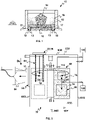
- the tray 10 is led to the outlet lock 58 of the dry cleaning device 32 where it can for example be gripped by the gripping device 54 in order to be extracted from the E32 enclosure, as shown in the figure 5 .
- the cleaned tray 10 follows the same path as on its arrival but in the opposite direction.
- the fork 142 brings the plate 10 back from the second support 132 towards the first support 130, then the first support 130 returns to the high position so as to bring the plate 10 back into the opening 76 of the base 74. Then, the cleaning chamber 68 is returned to its initial unturned position, after having taken care to open the door 112, so that the tray 10 is recovered by the elevator 84 and its piston 90 which finish driving the cleaned plate 10 to the chain conveyor 72 of the receiving means 64.
- the cleaning installation 20 is particularly suited to being installed in an additive manufacturing workshop comprising a plurality of additive manufacturing machines.
- the installation 20, and more particularly the dry cleaning device 32 can be adapted to carry out the cleaning of a tray 10 alone, that is to say without a jacket 12 forming a container 15 with this tray 10 .
- the installation 20 and the plates 10 can also be adapted so as to avoid the use of supports 13 of the plates 10.
- the two containment E32 and cleaning 68 enclosures of the dry cleaning device 32 provide double containment to better protect people from the toxicity of certain additive manufacturing powders.
- the present invention also relates to a method for dry cleaning an additive manufacturing plate 10 that can for example be implemented with the dry cleaning device 32 which has just been described.
- this method consists in separating the unconsolidated powder 16 from a plate 10 and in collecting it by imposing vibrations on the plate and by subjecting the plate to shocks.
- the vibrations applied to the plate 10 have frequencies preferably between 40 and 150 Hz, and the amplitudes of the oscillations of the plate 10 under the effect of the vibrations do not exceed 5 millimeters.
- a plurality of shocks are applied to a plate 10 using a body in motion and having a kinetic energy of 20 to 25 Joules when it comes into contact with the plate 10.
- the shocks are given in a direction orthogonal to the plane P10 of the plate 10, and for example using the rod 154 of the striker 120.
- a plate 10 being designed to be particularly rigid in its width and its length, it is more effective to apply these shocks perpendicular to the plate 10 and therefore in its height.
- a tray 10 undergoes 120 to 600 shocks during a dry cleaning cycle, at frequencies between 15 and 25 Hz.
- the vibrations are preferably imposed on the plate 10 in directions substantially parallel to the plane P10 of the plate 10, and for example using a vibrator 118.
- the vibrations can be imposed on the plate 10 in directions substantially parallel to the plane P10 of the plate 10 but different from each other.
- the vibrations are imposed on the plate 10 in two directions parallel to the plane P10 of the plate 10 but perpendicular to each other, and corresponding for example to the directions extending in the length and in the width of the plate 10.
- This combination of vibrations of different directions is advantageous because it makes it possible to best rid the manufactured parts and their cavities of grains of unconsolidated powder, and this regardless of the directions in which these parts and these cavities extend parallel to the plane P10 of the plate.
- vibration steps and shock steps are alternated several times.
- vibration and shock steps are carried out simultaneously.
- the method comprises a preliminary step consisting in turning over the plate 10, this turning over making it possible to recover a large part of the unconsolidated powder. 16 by gravity.
- the dry cleaning process can provide for varying the inclination of the plate 10 during the vibration and/or steps of applying shocks to the plate 10.
- the dry cleaning process takes place in a confined volume V68, and preferably doubly confined thanks to the confinement enclosure E32 of the dry cleaning device 32.
- the dry cleaning process comprises a step subsequent to the vibration and the application of shocks consisting in evacuating from this confined volume V68 the grains unconsolidated powder 16 resulting from the dry cleaning of the plate 10, for example with a view to its storage and its reuse.
- the suction intended for the recovery of the unconsolidated powder 16 which has fallen into the top 78 of the bell 70 only operates for a few seconds.
- the method provides that the confined volume V68 is subjected to additional suction during cleaning, this additional suction having the purpose to eliminate any powder mists that may form inside the enclosure 68 for dry cleaning during a dry cleaning cycle.
- the complementary suction is at least maintained within the enclosure of the dry cleaning enclosure 68 during the vibration of a plate 10 and during the application of shocks to the plate 10.
- the method provides that the containment volume V32 of the dry-cleaning device 32 is also subject to additional aspiration.
- the dry cleaning device 32 turns over and cleans only the plate 10 and the manufactured parts integral with this plate 10. Indeed, it is not useful to turn over and clean the jacket 12 because the translation of the plate 10 with its support 13 and the seal 19 is sufficient to clear the interior walls of the shirt 12 grains of unconsolidated powder. In addition, the reversal of the shirt 12 with the plate 10 would represent additional energy consumption and therefore useless.
- the dry cleaning device 32 makes it possible to separate the plate 10 and the manufactured parts from the jacket 12 in order to transfer only the plate 10 and the manufactured parts to the wet cleaning device 34. Indeed, cleaning wet liners 12 is not necessary.
Description
L'invention se situe dans le domaine de la fabrication additive à base de poudre par frittage ou fusion des grains de cette poudre à l'aide d'un faisceau énergétique à rayonnement électromagnétique, comme par exemple un faisceau laser, et/ou d'un faisceau de particules, comme par exemple un faisceau d'électrons.The invention lies in the field of powder-based additive manufacturing by sintering or fusion of the grains of this powder using an electromagnetic radiation energy beam, such as for example a laser beam, and/or a particle beam, such as an electron beam.
Plus précisément, l'invention concerne le nettoyage des plateaux de fabrication additive et des pièces fabriquées sur ces plateaux.More specifically, the invention relates to the cleaning of additive manufacturing trays and parts manufactured on these trays.
Lors de la mise en oeuvre d'un procédé de fabrication additive au sein d'une machine de fabrication additive, une première couche de poudre est déposée sur un plateau de fabrication additive monté coulissant à l'intérieur d'une enceinte entourant le plateau de fabrication. Ensuite, cette première couche de poudre est consolidée selon un motif prédéterminé à l'aide de l'un des faisceaux énergétiques précités. Puis, le plateau de fabrication est abaissé dans son enceinte de manière à permettre le dépôt et la consolidation d'une deuxième couche de poudre. Enfin, les étapes d'abaissement du plateau puis de dépôt et de consolidation de couches de poudre se succèdent jusqu'au dépôt et à la consolidation de la dernière couche de poudre utile à la fabrication des pièces à réaliser.During the implementation of an additive manufacturing process within an additive manufacturing machine, a first layer of powder is deposited on an additive manufacturing plate mounted to slide inside an enclosure surrounding the manufacturing. Then, this first layer of powder is consolidated according to a predetermined pattern using one of the aforementioned energy beams. Then, the manufacturing platform is lowered into its enclosure so as to allow the deposition and consolidation of a second layer of powder. Finally, the stages of lowering the plate then depositing and consolidating layers of powder follow one another until the deposit and consolidation of the last layer of powder useful for the manufacture of the parts to be produced.
Selon un inconvénient rencontré à la fin de ce procédé de fabrication additive, la ou les pièces fabriquées se retrouvent noyées au milieu d'une importante quantité de poudre non consolidée qui doit être évacuée.According to a drawback encountered at the end of this additive manufacturing process, the manufactured part or parts find themselves embedded in the middle of a large quantity of unconsolidated powder which must be evacuated.
Selon une première méthode, le plateau de fabrication est extrait de la machine, avec ou sans son enceinte, et un opérateur dégage manuellement les grains de poudre en s'aidant d'outils tels une brosse et une soufflette à air comprimé ou un aspirateur.According to a first method, the manufacturing plate is extracted from the machine, with or without its enclosure, and an operator manually releases the grains of powder using tools such as a brush and a compressed air blower or a vacuum cleaner.
En raison de sa mise en oeuvre essentiellement manuelle, cette première méthode de nettoyage est difficilement compatible avec une application industrielle.Due to its essentially manual implementation, this first cleaning method is not easily compatible with an industrial application.
De plus, ce nettoyage manuel peut être dangereux pour l'opérateur car les poudres utilisées en fabrication additive contiennent généralement des composés chimiques toxiques pouvant être inhalés par les opérateurs malgré leurs équipements de protection.In addition, this manual cleaning can be dangerous for the operator because the powders used in additive manufacturing generally contain toxic chemical compounds that can be inhaled by operators despite their protective equipment.
Enfin, selon un autre inconvénient, si la poudre non consolidée n'est pas maintenue sous atmosphère protectrice pendant le nettoyage, elle doit subir plusieurs traitements avant de pouvoir être réutilisée.Finally, according to another drawback, if the unconsolidated powder is not kept under a protective atmosphere during cleaning, it must undergo several treatments before it can be reused.
Aussi, certains fabricants de machines de fabrication additive ont modifié leurs machines de manière à mieux protéger la santé des opérateurs et de façon à pouvoir réutiliser immédiatement la poudre issue du nettoyage des pièces fabriquées.Also, some manufacturers of additive manufacturing machines have modified their machines to better protect the health of operators and to be able to immediately reuse the powder resulting from the cleaning of the manufactured parts.
Le document
Plus en détail, ces moyens comprennent des ouvertures réalisées dans une paroi de l'enceinte de fabrication, un bras robot installé dans l'enceinte de fabrication, et un tuyau d'aspiration manipulable dans cette enceinte de fabrication. De plus, les ouvertures sont munies de gants de protection permettant à un opérateur d'introduire ses mains dans l'enceinte de fabrication pour procéder au nettoyage des pièces fabriquées à l'aide du tuyau d'aspiration, et l'opérateur peut commander le bras robot depuis l'extérieur de la machine afin de déplacer facilement les pièces les plus lourdes.In more detail, these means comprise openings made in a wall of the manufacturing enclosure, a robot arm installed in the manufacturing enclosure, and a suction pipe that can be manipulated in this manufacturing enclosure. In addition, the openings are provided with protective gloves allowing an operator to introduce his hands into the manufacturing enclosure to clean the manufactured parts using the suction pipe, and the operator can control the robot arm from outside the machine to easily move the heaviest parts.
Grâce aux moyens décrits dans le brevet européen
Toutefois, le nettoyage reste une opération manuelle nécessitant le travail d'un opérateur, et comme ce nettoyage manuel a lieu dans l'enceinte de fabrication de la machine, celle-ci ne peut être utilisée pour fabriquer de nouvelles pièces pendant toute la durée du nettoyage.However, cleaning remains a manual operation requiring the work of an operator, and as this manual cleaning takes place within the manufacturing enclosure of the machine, the latter cannot be used to manufacture new parts throughout the duration of the cleaning.
Aussi, dans le brevet européen
Dans un premier mode de réalisation de ce dispositif de nettoyage, un couvercle muni de deux ouvertures en vis-à-vis l'une de l'autre est placé sur le sommet du récipient, et une source d'air comprimé est reliée à la première ouverture tandis qu'un réservoir est relié à la deuxième ouverture. Ainsi, et en faisant monter progressivement le plateau de fabrication et les pièces fabriquées vers le sommet du récipient, le flux d'air comprimé pousse la poudre non consolidée vers la deuxième ouverture et donc dans le réservoir.In a first embodiment of this cleaning device, a cover provided with two openings facing each other is placed on the top of the container, and a source of compressed air is connected to the first opening while a tank is connected to the second opening. Thus, and by gradually raising the manufacturing plate and the manufactured parts towards the top of the container, the flow of compressed air pushes the unconsolidated powder towards the second opening and therefore into the reservoir.
Selon un inconvénient de ce premier mode de réalisation, il existe un risque de polluer la poudre avec le flux d'air comprimé utilisé pour pousser la poudre vers le réservoir.According to a drawback of this first embodiment, there is a risk of polluting the powder with the flow of compressed air used to push the powder towards the reservoir.
Dans un second mode de réalisation, le sommet du récipient est équipé d'un col évasé comprenant un bec permettant d'évacuer la poudre non consolidée lorsque le récipient est incliné grâce à des moyens appropriés et que le plateau de fabrication monte progressivement.In a second embodiment, the top of the container is equipped with a flared neck comprising a spout allowing the unconsolidated powder to be evacuated when the container is tilted using appropriate means and the build plate rises gradually.
Dans ce second mode de réalisation, la poudre non consolidée est avantageusement évacuée par gravité vers un réservoir. Ensuite, le réservoir étant équipé d'un tamis de réception des pièces fabriquées, des vibrations sont utilisées pour finir de séparer les grains de poudre des pièces fabriquées.In this second embodiment, the unconsolidated powder is advantageously evacuated by gravity to a reservoir. Then, the tank being equipped with a sieve for receiving the manufactured parts, vibrations are used to finish separating the grains of powder from the manufactured parts.
Si ce second mode de réalisation du dispositif de nettoyage n'emploie pas de flux d'air comprimé susceptible de polluer la poudre non consolidée, il ne permet pas non plus de nettoyer parfaitement les pièces fabriquées.If this second embodiment of the cleaning device does not use a flow of compressed air liable to pollute the unconsolidated powder, it does not allow the manufactured parts to be perfectly cleaned either.
En effet, sous l'effet des vibrations, les grains de poudre les plus fins sont susceptibles de flotter dans l'air sous forme d'un brouillard et de se déposer à nouveau sur les pièces fabriquées une fois la mise en vibration stoppée.Indeed, under the effect of vibrations, the finest powder grains are likely to float in the air in the form of a mist and to be deposited again on the manufactured parts once the vibration has stopped.
De plus, dans le cas où les pièces fabriquées sont de formes complexes avec des cavités susceptibles de contenir des agglomérats de poudre, de simples vibrations ne suffisent pas à désagréger les amas de poudre qui peuvent se former dans ces cavités lors de la fabrication additive.Moreover, in the case where the manufactured parts are of complex shapes with cavities likely to contain agglomerates of powder, simple vibrations are not enough to disintegrate the clumps of powder which can form in these cavities during additive manufacturing.
Enfin, la simple utilisation de vibrations ne permet pas de retirer tous les grains de poudre collés aux pièces fabriquées comme le permet par exemple un brossage manuel.Finally, the simple use of vibrations does not make it possible to remove all the grains of powder stuck to the manufactured parts as manual brushing allows for example.
Aussi, la présente invention a pour objectif de parer à au moins l'un des inconvénients des dispositifs décrits dans les documents de l'art antérieur, tout en permettant de nettoyer un plateau de fabrication seul ou avec les pièces qui ont été fabriquées sur ce plateau et qui restent solidaires de ce plateau à la fin du cycle de fabrication additive.Also, the present invention aims to obviate at least one of the drawbacks of the devices described in the documents of the prior art, while making it possible to clean a manufacturing plate alone or with the parts which have been manufactured on this tray and which remain attached to this tray at the end of the additive manufacturing cycle.
A cet effet, l'invention a pour objet un dispositif de nettoyage à sec d'un plateau de fabrication additive effectuée à l'aide de poudre, selon la revendication 1.To this end, the subject of the invention is a device for the dry cleaning of an additive manufacturing plate made using powder, according to claim 1.
Selon l'invention, le poste de nettoyage à sec comprend des moyens aptes à imposer des vibrations au plateau à nettoyer et des moyens aptes à faire subir des chocs à ce plateau.According to the invention, the dry cleaning station comprises means capable of imposing vibrations on the plate to be cleaned and means capable of subjecting this plate to shocks.
Grâce à l'application de chocs au plateau, les amas de poudre susceptibles de se former dans les cavités des pièces fabriquées se désagrègent, et grâce l'application de vibrations, la majorité des grains de poudre non consolidée sont progressivement amenés à se séparer des pièces fabriquées et du plateau de fabrication en chutant par gravité depuis le plateau ou depuis les pièces fabriquées.Thanks to the application of shocks to the plate, the clumps of powder likely to form in the cavities of the manufactured parts disintegrate, and thanks to the application of vibrations, the majority of the grains of unconsolidated powder are gradually brought to separate from the manufactured parts and the build plate by gravity dropping from the plate or from the manufactured parts.
Afin de réaliser le nettoyage à sec dans un volume confiné, le dispositif de nettoyage à sec comprend une enceinte de nettoyage à l'intérieur de l'enceinte de confinement, cette enceinte de nettoyage prenant la forme d'une cloche montée sur une embase, cette embase comprenant une ouverture de réception d'un plateau à nettoyer, et les moyens de réception permettant de transporter un plateau du sas d'entrée jusqu'à l'ouverture de l'embase de l'enceinte de nettoyage.In order to carry out the dry cleaning in a confined volume, the dry cleaning device comprises a cleaning enclosure inside the confinement enclosure, this cleaning enclosure taking the form of a bell mounted on a base, this base comprising an opening for receiving a tray to be cleaned, and the receiving means making it possible to transport a tray from the entry lock to the opening of the base of the cleaning enclosure.
Dans une variante de réalisation préférée, les moyens aptes à imposer des vibrations et les moyens aptes à faire subir des chocs sont supportés par l'embase de l'enceinte de nettoyage et prévus à côté de l'ouverture recevant le plateau à nettoyer.In a preferred variant embodiment, the means capable of imposing vibrations and the means capable of causing shocks are supported by the base of the cleaning enclosure and provided next to the opening receiving the tray to be cleaned.
Aussi, l'enceinte de nettoyage comprend des moyens internes de convoyage d'un plateau entre son ouverture et les moyens du poste de nettoyage à sec.Also, the cleaning enclosure comprises internal means for conveying a tray between its opening and the means of the dry cleaning station.
En vue du retournement d'un plateau à nettoyer et de la récupération de la poudre non consolidée par gravité, l'enceinte de nettoyage est montée pivotante autour d'un axe horizontal, et de préférence de manière à pouvoir pivoter d'au moins 180° à l'intérieur de l'enceinte de confinement du dispositif de nettoyage à sec.With a view to turning over a tray to be cleaned and recovering the unconsolidated powder by gravity, the cleaning enclosure is mounted to pivot about a horizontal axis, and preferably so as to be able to pivot by at least 180 ° inside the enclosure of the dry cleaning device.
Afin de pouvoir modifier l'angle d'inclinaison du plateau pendant le nettoyage à sec, le dispositif de nettoyage à sec comprend un actionneur permettant de contrôler l'angle de rotation de l'enceinte de nettoyage autour de son axe horizontal.In order to be able to modify the angle of inclination of the plate during dry cleaning, the dry cleaning device comprises an actuator making it possible to control the angle of rotation of the cleaning enclosure around its horizontal axis.
En vue de faciliter et d'accélérer la récupération de la poudre non consolidée, l'enceinte de nettoyage est équipée de moyens de récupération de poudre par aspiration.In order to facilitate and accelerate the recovery of the unconsolidated powder, the cleaning chamber is equipped with means for recovering the powder by suction.
Comme la cloche de l'enceinte de nettoyage est retournée préalablement à la mise en oeuvre des moyens de mise en vibration et d'application de chocs, les moyens de récupération de poudre par aspiration sont reliés au sommet de la cloche de l'enceinte de nettoyage.As the bell of the cleaning enclosure is turned over prior to the implementation of the means for vibrating and applying shocks, the means for recovering powder by suction are connected to the top of the bell of the cleaning.
Avantageusement, la cloche comprend un orifice d'aspiration de poudre entre son embase et son sommet, cet orifice étant relié à des moyens de récupération d'un brouillard de poudre par aspiration et permettant d'aspirer les grains de poudre du brouillard de poudre qui se forme lors du retournement de la cloche.Advantageously, the bell comprises a powder suction orifice between its base and its top, this orifice being connected to means for recovering a mist of powder by suction and making it possible to suck up the grains of powder from the mist of powder that forms when the bell is turned over.
En vue d'améliorer la protection des personnes vis-à-vis de la toxicité de certaines poudres de fabrication additive, les moyens de récupération d'un brouillard de poudre par aspiration sont aussi reliés au volume intérieur de l'enceinte de confinement du dispositif de nettoyage à sec.In order to improve the protection of people against the toxicity of certain additive manufacturing powders, the means for recovering a mist of powder by suction are also connected to the interior volume of the confinement enclosure of the device. dry cleaning.
D'autres caractéristiques et avantages de l'invention apparaîtront dans la description qui va suivre. Cette description, donnée à titre d'exemple et non limitative, se réfère aux dessins joints en annexe sur lesquels :
- la
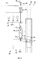
figure 1 est une vue schématique d'un plateau de fabrication additive à nettoyer, le plateau étant équipé d'un support et d'une chemise, - la
figure 2 est une vue schématique de dessus d'un premier mode de réalisation d'une installation de nettoyage selon l'invention, avec des flèches illustrant un cycle de nettoyage d'un plateau, - la
figure 3 est une vue schématique de dessus d'un premier mode de réalisation d'une installation de nettoyage selon l'invention, avec des flèches illustrant l'utilisation de l'installation selon l'invention pour approvisionner un atelier de fabrication additive avec des plateaux propres et/ou neufs, - la
figure 4 est une vue schématique de dessus d'un second mode de réalisation d'une installation de nettoyage selon l'invention, avec des flèches illustrant un cycle de nettoyage d'un plateau et l'utilisation de l'installation selon l'invention pour approvisionner un atelier de fabrication additive avec des plateaux propres et/ou neufs, - la
figure 5 est une vue schématique de dessus d'un dispositif de nettoyage à sec selon l'invention, - la
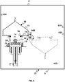
figure 6 est une vue schématique de face d'un dispositif de nettoyage à sec selon l'invention, cette vue illustrant aussi la réception d'un plateau de fabrication additive à nettoyer par le dispositif de nettoyage à sec, - la
figure 7 est une vue de détail de lafigure 6 , cette vue illustrant aussi l'arrivée du plateau à nettoyer dans l'enceinte de nettoyage du dispositif de nettoyage à sec, - la
figure 8 est une vue schématique de côté de l'enceinte de nettoyage du dispositif de nettoyage à sec selon l'invention, cette vue illustrant aussi le retournement du plateau à nettoyer prévu par l'invention, et - la
figure 9 est aussi une vue schématique de côté de l'enceinte de nettoyage du dispositif de nettoyage à sec selon l'invention, mais cette vue illustre plus particulièrement le nettoyage du plateau à nettoyer par le dispositif de nettoyage à sec selon l'invention.
- the
figure 1 is a schematic view of an additive manufacturing platform to be cleaned, the platform being equipped with a support and a sleeve, - the
picture 2 - the
picture 3 is a schematic top view of a first embodiment of a cleaning installation according to the invention, with arrows illustrating the use of the installation according to the invention to supply an additive manufacturing workshop with clean trays and/or new, - the
figure 4 is a schematic top view of a second embodiment of a cleaning installation according to the invention, with arrows illustrating a cycle for cleaning a tray and the use of the installation according to the invention to supply an additive manufacturing workshop with clean and/or new trays, - the
figure 5 is a schematic top view of a dry cleaning device according to the invention, - the
figure 6 is a schematic front view of a dry cleaning device according to the invention, this view also illustrating the reception of an additive manufacturing plate to be cleaned by the dry cleaning device, - the
figure 7 is a detail view of thefigure 6 , this view also illustrating the arrival of the plate to be cleaned in the cleaning enclosure of the dry cleaning device, - the
figure 8 is a schematic side view of the cleaning enclosure of the dry cleaning device according to the invention, this view also illustrating the reversal of the tray to clean provided by the invention, and - the
figure 9 is also a schematic side view of the cleaning enclosure of the dry cleaning device according to the invention, but this view more particularly illustrates the cleaning of the plate to be cleaned by the dry cleaning device according to the invention.
La présente invention est relative au nettoyage de plateaux 10 de fabrication additive.The present invention relates to the cleaning of
Un plateau de fabrication additive 10 prend la forme d'un support parallélépipédique, généralement métallique, et de quelques centimètres de hauteur et de plusieurs dizaines de centimètres de longueur et de largeur dans un plan P10.An
De façon connue, un tel plateau 10 est utilisé comme support de fabrication des pièces à fabriquer à l'intérieur de la chambre de fabrication d'une machine de fabrication additive. Plus en détail, le plateau est monté à l'intérieur d'une enceinte de fabrication entourant le plateau dans cette chambre de fabrication, et le plateau est monté mobile en translation verticale dans cette enceinte de fabrication afin de pouvoir être abaissé avant chaque nouveau dépôt d'un lit de poudre non consolidée.In known manner, such a
Comme le montre la
En étant assemblé l'un à l'autre, le plateau 10 et la chemise 12 forment un container 15. Ce container 15 est monté de manière amovible à l'intérieur d'une machine de fabrication additive afin de pouvoir être extrait de la chambre de fabrication de cette machine avec les pièces fabriquées 14 et la poudre non consolidée 16 qui les entoure.By being assembled to one another, the
Avantageusement, ce container 15 permet de faciliter le transport des pièces fabriquées 14 et de la poudre non consolidée 16 depuis une machine de fabrication additive vers un autre dispositif présent dans un atelier de fabrication additive ou vers une installation de nettoyage telle que celle proposée par la présente invention.Advantageously, this
En vue d'un guidage et d'un transfert automatisé, un support 13 équipe le plateau 10. Ce support 13 prend la forme d'un cadre sur lequel vient s'emboîter un plateau de fabrication 10. Afin d'être maintenu en position par des goujons ou d'autres types d'axes rétractables, ce support 13 comprend des alésages 17. Enfin, ce support 13 est équipé d'un joint d'étanchéité périphérique 19 pour éviter les fuites de poudre lorsque le plateau 10 et son support 13 sont déplacés en translation à l'intérieur de la chemise 12.With a view to guiding and automated transfer, a
La présente invention a pour objectifs principaux de récupérer, sans l'altérer, l'importante quantité de poudre non consolidée 16 qui entoure les pièces 14 dans un container 15 et de débarrasser au mieux les pièces fabriquées 14 et les plateaux de fabrication additive 10 des grains de poudre non consolidée.The main objectives of the present invention are to recover, without altering it, the large quantity of
A cet effet, l'invention prévoit une installation 20 de nettoyage de plateaux de fabrication additive telle qu'illustrée en
Cette installation 20 comprend un sas d'entrée 22 permettant de recevoir un plateau 10 à nettoyer depuis une machine de fabrication additive, des moyens de transport 24 adaptés étant prévus pour transporter le container 15, les pièces fabriquées 14 et la poudre non consolidée 16 dans les meilleures conditions possibles depuis une machine de fabrication additive jusqu'au sas d'entrée 22 de l'installation.This
Afin de pouvoir extraire un plateau 10 nettoyé de l'installation, l'installation 20 comprend aussi un sas de sortie 26. L'ensemble de l'installation 20 étant de préférence confiné dans une enceinte de protection 28 partiellement représentée sur les
Comme l'illustrent les différentes flèches en
Afin d'assurer un nettoyage optimal des plateaux 10, l'installation 20 comprend un dispositif de nettoyage à sec 32 permettant de nettoyer un plateau 10 à l'aide de vibrations et de chocs dans une première enceinte de confinement E32, un dispositif de nettoyage humide 34 permettant de nettoyer un plateau 10 à l'aide d'au moins un liquide dans une seconde enceinte de confinement E34, et au moins un dispositif de convoyage permettant de transporter un plateau 10 entre l'enceinte de nettoyage à sec E32, l'enceinte de nettoyage humide E34, et le sas de sortie 26 de l'installation.In order to ensure optimum cleaning of the
Plus précisément, le dispositif de nettoyage à sec 32 vise à récupérer une quantité maximale de poudre non consolidée sans l'altérer afin de pouvoir réutiliser cette poudre le plus rapidement possible, sans traitement préalable de séchage mais seulement avec un tamisage visant à maîtriser la granulométrie de la poudre ainsi recyclée. Consécutivement, le dispositif de nettoyage humide 34 vise à nettoyer parfaitement les pièces fabriquées 14 et les plateaux de fabrication 10 en retirant tous les grains de poudre non consolidée qui peuvent rester collés aux pièces et aux plateaux après le nettoyage à sec.More specifically, the
Afin d'obtenir un nettoyage parfait des pièces fabriquées 14 et des plateaux de fabrication 10, le dispositif de nettoyage humide 34 comprend dans son enceinte E34 au moins un poste de lavage 38 d'un plateau 10 avec un liquide de nettoyage et au moins un poste de rinçage 40 d'un plateau 10 avec un liquide de rinçage.In order to obtain perfect cleaning of the manufactured
De préférence, le poste de lavage 38 prend la forme d'une cuve remplie de liquide de nettoyage et équipée de moyens, tel un transducteur, permettant d'émettre des ondes ultrasonores de très hautes fréquences, de 20 kHz de préférence et éventuellement de 45kHz, dans ce liquide de nettoyage. Ainsi, lorsque le plateau 10 et les pièces 14 à nettoyer sont plongées dans le liquide de nettoyage, les ondes ultrasonores génèrent par un phénomène de cavitation des bulles microscopiques qui implosent sous l'effet de ces mêmes ondes, et ces implosions provoquent des turbulences dans le liquide de nettoyage permettant de détacher les derniers grains de poudre encore collés aux pièces fabriquées 14 et à leur plateau de fabrication 10. Avantageusement, la taille microscopique des bulles leur permet de pénétrer dans les plus petites cavités des pièces fabriquées 14.Preferably, the
Idéalement, le liquide de nettoyage est une solution aqueuse et le liquide de rinçage est aussi une solution aqueuse.Ideally, the cleaning liquid is an aqueous solution and the rinsing liquid is also an aqueous solution.
En vue de faciliter l'étape de lavage et d'améliorer la qualité du nettoyage réalisé, le dispositif de nettoyage humide 34 peut comprendre dans son enceinte E34 un poste de prélavage 42, évidemment situé en amont du poste de lavage 38.In order to facilitate the washing step and to improve the quality of the cleaning carried out, the
Ce poste de prélavage 42 peut prendre la forme d'une cuve remplie de liquide de prélavage et le liquide de prélavage est de préférence une solution aqueuse.This
Le poste de rinçage 40 peut aussi faire office de poste de séchage et comprendre des moyens de séchage des plateaux nettoyés et des pièces fabriquées 14, ces moyens de séchage prenant par exemple la forme d'une cuve équipée d'un souffleur d'air chaud.The rinsing
En vue d'une automatisation complète de l'installation, le dispositif de nettoyage humide 34 comprend dans son enceinte E34 des moyens de convoyage (non représentés) permettant de convoyer de manière automatisée les plateaux 10 à nettoyer et les pièces fabriquées 14 accrochées à ces plateaux 10 entre les différents postes de prélavage 42, de lavage 38 et de rinçage 40.With a view to complete automation of the installation, the
Dans une variante de réalisation non illustrée sur les figures, le dispositif de nettoyage humide 34 peut comprendre une seule chambre de travail dans laquelle les plateaux 10 peuvent être prélavés, lavés et éventuellement séchés, et différentes chambres de stockage pour stocker les plateaux 10 avant, entre et/ou après ces différentes étapes.In a variant embodiment not illustrated in the figures, the
Comme l'illustre la
Dans un premier mode de réalisation de l'installation illustré par les
Dans l'objectif d'utiliser le sas de sortie 26 de l'installation pour introduire des plateaux 10 neufs et/ou propres dans un atelier de fabrication additive via l'installation de nettoyage 20, le second convoyeur 46 permet aussi de transporter des plateaux 10 depuis le sas de sortie 26 de l'installation 20 vers l'enceinte E34 du dispositif de nettoyage humide 34, et le premier convoyeur 44 permet aussi de transporter des plateaux 10 depuis l'enceinte E34 du dispositif de nettoyage humide 34 vers l'enceinte E32 du dispositif de nettoyage à sec 32.With the aim of using the
Dans un tel cas d'utilisation de l'installation 20 pour alimenter un atelier de fabrication additive en plateaux 10 neufs et/ou propres, il peut être prévu de procéder à un nettoyage humide de ces plateaux 10 dans le dispositif de nettoyage humide 34. On s'assure ainsi du parfait nettoyage et de la décontamination de ces plateaux 10 avant leur utilisation au sein d'une machine de fabrication additive, ces plateaux 10 ayant pu être pollués à l'extérieur E de l'enceinte 28 de l'installation 20 lors d'une manutention manuelle ou lors d'un stockage sans protection.In such a case of use of the
Dans ce premier mode de réalisation de l'installation 20, les deux convoyeurs 44,46 peuvent être des convoyeurs à bande.In this first embodiment of the
Dans un second mode de réalisation de l'installation 20 illustré par la
Plus en détail, le convoyeur 36 peut être un convoyeur à bande, chaque zone de stockage 48,50 peut prendre la forme d'un dispositif de stockage ouvert tel une étagère, et le bras manipulateur 52 est un bras articulé au bout duquel est monté un dispositif de préhension 54 d'un plateau 10 comme par exemple une pince.More in detail, the
Grâce à la présence d'au moins une zone de stockage 48,50, le bras manipulateur 52 permet par exemple de gérer les étapes de nettoyage à sec et humide de différents plateaux 10 pendant que le convoyeur 36 est utilisé pour transférer des plateaux propres 10 depuis le sas de sortie 26 jusqu'au dispositif de nettoyage à sec 32.Thanks to the presence of at least one
De préférence, il est prévu deux zones de stockage 48 et 50 temporaires afin d'éviter de stocker dans une même zone des plateaux 10 propres et des plateaux 10 en cours de nettoyage.Preferably, two
Toujours de préférence, le bras manipulateur 52 est mobile en rotation autour de différents axes horizontaux et/ou verticaux afin de déplacer le plus rapidement possible chaque plateau 10 d'un point à un autre.Still preferably, the
Selon une variante non illustrée et plus économique de ce second mode de réalisation, le bras manipulateur 52 peut être supprimé et le convoyeur 36 peut être agencé de manière à assurer seul le transport des plateaux 10 entre l'enceinte de nettoyage à sec E32, l'enceinte de nettoyage humide E34, et le sas de sortie 26 de l'installation.According to a non-illustrated and more economical variant of this second embodiment, the
Pour réaliser le nettoyage à sec des plateaux 10 à l'aide de chocs et de vibrations, l'invention propose un dispositif de nettoyage à sec 32 d'un plateau 10.To carry out the dry cleaning of the
Comme indiqué précédemment, ce dispositif de nettoyage à sec 32 comprend une enceinte de confinement E32. Afin de recevoir un plateau 10 à nettoyer, cette enceinte de confinement E32 comprend au moins un sas d'entrée 56, et afin d'évacuer un plateau 10 nettoyé, cette enceinte de confinement E32 comprend aussi un sas de sortie 58. Avantageusement, le sas d'entrée 56 de l'enceinte E32 du dispositif de nettoyage à sec 32 est aussi le sas d'entrée 22 de l'installation 20.As indicated previously, this
L'enceinte de nettoyage à sec E32 étant formée sur le sol S par une paroi avant 60F, une paroi arrière 60R, une paroi latérale gauche 62G, une paroi latérale droite 62D et un plafond P, le sas d'entrée 56 est prévu au travers de la paroi arrière 60R de l'enceinte de nettoyage à sec E32, et le sas de sortie 58 est prévu au travers de la paroi latérale droite 62D de l'enceinte de nettoyage à sec E32.The dry cleaning enclosure E32 being formed on the floor S by a
Comme l'illustre la
Plus précisément, les moyens de réception 64 permettent de recevoir et de transporter un container 15 formé par un plateau 10 à nettoyer, son support 13 et sa chemise 12.More specifically, the receiving means 64 make it possible to receive and transport a
Ces moyens de réception 64 prennent par exemple la forme d'un convoyeur à chaîne 72. Ce convoyeur à chaîne 72 s'étend horizontalement à l'intérieur de l'enceinte de nettoyage à sec E32, et dans une direction longitudinale DL parallèle aux plans des parois latérales 62G,62D de l'enceinte E32 et perpendiculaire aux parois avant 60F et arrière 60R de cette enceinte. Ainsi, ce convoyeur à chaîne 72 permet de transporter un container 15, et donc un plateau 10 à nettoyer, depuis le sas d'entrée 56 de l'enceinte E32 vers le poste de nettoyage à sec 66.These reception means 64 take for example the form of a
En vue de faciliter la récupération de la poudre non consolidée 16 contenue dans un container 15, le dispositif de nettoyage à sec 32 comprend une seconde enceinte de nettoyage 68 à l'intérieur de sa première enceinte de confinement E32.In order to facilitate the recovery of the
Cette seconde enceinte de nettoyage 68 prend la forme d'une cloche 70 montée sur une embase 74, et cette embase 74 comprend une ouverture 76 de réception d'un plateau 10 à nettoyer.This
Plus précisément, l'embase 74 est sensiblement plane et rectangulaire, tandis que la cloche 70 a une forme pyramidale S70 s'étendant autour d'un axe central A70 perpendiculaire au plan P74 de l'embase 74. Parallèlement, l'ouverture 76 est de forme et de dimensions ajustées ou ajustables à la forme et aux dimensions des plateaux 10 à nettoyer.More specifically, the
La forme pyramidale de la cloche 70 autour de son axe central A70 facilite l'écoulement et la récupération de la poudre non consolidée 16 lorsque cette cloche 70 est retournée avec un plateau 10 à nettoyer.The pyramidal shape of the
Dans une variante préférée de réalisation illustrée sur les
Dans d'autres variantes, la cloche peut aussi prendre une forme entièrement pyramidale, partiellement ou entièrement conique, partiellement ou entièrement tronconique, ou tout autre forme permettant de former un entonnoir lorsque la cloche 70 est retournée.In other variants, the bell can also take an entirely pyramidal, partially or entirely conical, partially or entirely frustoconical shape, or any other shape making it possible to form a funnel when the
Afin de contrôler l'écoulement de la poudre non consolidée 16 lorsque la cloche 70 est retournée de telle manière que son embase 74 se situe au-dessus de son sommet 78 comme l'illustrent les
Comme cela vient d'être indiqué, l'invention prévoit de retourner la cloche 70 et le plateau 10 en vue de récupérer la poudre non consolidée 16 entourant la ou les pièces fabriquées 14 dans un container 15.As has just been indicated, the invention provides for turning over the
Toutefois, dans un premier temps, il est nécessaire d'emmener le container 15 comprenant le plateau 10 à nettoyer et la poudre non consolidée 16 à récupérer vers l'ouverture 76 de l'embase 74 de l'enceinte de nettoyage 68.However, initially, it is necessary to take the
A cet effet, il est prévu que l'enceinte de nettoyage 68 soit dans une position initiale correspondant à une position non retournée dans laquelle la cloche 70 et son sommet 78 se situent au-dessus de l'embase 74. Dans cette position initiale de l'enceinte de nettoyage 68, le plan P74 de l'embase 74 est sensiblement horizontal, comme illustré sur les
Ensuite, les moyens de réception 64 permettent de transporter un container 15, et donc un plateau 10, du sas d'entrée 56 de l'enceinte de confinement E32 jusqu'en face de l'ouverture 76 de l'embase 74 de l'enceinte de nettoyage 68 lorsque cette enceinte de nettoyage 68 se trouve dans sa position initiale.Then, the reception means 64 make it possible to transport a
En complément des moyens de réception 64, le dispositif de nettoyage à sec 32 comprend un ascenseur 84 permettant d'emmener un plateau 10 à nettoyer depuis les moyens de réception 64 jusqu'à l'ouverture 76.In addition to the reception means 64, the
A cet effet et comme illustré par les
Parallèlement à la mise en translation verticale T1 du plateau 10 et de son support 13, l'ascenseur 84 permet de déplacer la chemise 12 en translation verticale T2 parallèlement à son axe central A12 et vers l'embase 74 de l'enceinte de nettoyage 68. Ainsi, le bord supérieur 86 de la chemise 12 est plaqué contre le bord inférieur 88 de l'ouverture 76 de l'embase 74, ce qui permet d'éviter les fuites de poudre non consolidée 16 lorsque le plateau 10 s'élève dans la chemise 12 et que cette poudre est progressivement transvasée du container 15 vers le volume intérieur V68 de l'enceinte de nettoyage 68.Parallel to the setting in vertical translation T1 of the
Pour la mise en oeuvre de la translation verticale T1 du plateau 10 et de son support 13, l'ascenseur 84 comprend par exemple un piston 90 guidé en translation à l'intérieur d'un corps 92 et animé en translation par un moteur 94 et une vis sans fin 96.For the implementation of the vertical translation T1 of the
Pour la mise en oeuvre de la translation T2 de la chemise 12, l'ascenseur 84 comprend par exemple une plaque 98 guidée en translation autour de la tige 89 du piston 90 et animée en translation par des ressorts de compression 100 en appui sur une autre plaque 102 fixée au corps 92.For the implementation of the translation T2 of the
Avantageusement, les plaques 98,102 et les ressorts 100 sont dimensionnés et positionnés par rapport corps 92 et au piston 90 de façon que la mise en translation du piston 90 par le moteur 94 entraîne aussi la mise en translation de la plaque 98 sous l'effet des ressorts 100.Advantageously, the plates 98,102 and the
Une fois le plateau 10 arrivé dans le plan P74 de l'embase 74, la translation T1 du plateau est stoppée, et des éléments de verrouillage tels des goujons 104 viennent immobiliser le support 13 dans l'ouverture 76 de l'embase 74, ces goujons 104 pénétrant à cet effet dans les alésages 17 prévus dans le support 13.Once the
Avantageusement, dans cette position du plateau 10 par rapport à l'embase 74, le joint d'étanchéité périphérique 19 du support 13 réalise aussi l'étanchéité entre le support 13 et l'embase 74, et donc entre le plateau 10 et l'embase 74.Advantageously, in this position of the
Lorsque le plateau 10 est solidarisé à l'embase 74, la ou les pièces fabriquées 14 et la poudre non consolidée 16 se trouvent dans le volume intérieur V68 de l'enceinte de nettoyage 68, ce qui permet d'envisager un retournement de cette enceinte de nettoyage 68 pour récupérer par gravité la poudre non consolidée 16 et procéder au nettoyage à sec du plateau 10 et de la ou des pièces fabriquées 14.When the
En vue de ce retournement, l'enceinte de nettoyage 68 est montée pivotante autour d'un axe A68 de préférence horizontal.For this reversal, the cleaning
Comme l'illustre la
En vue d'une automatisation complète de l'installation, un actionneur tel un moteur électrique 106 permet d'entraîner l'enceinte 68 en rotation autour de son axe A68.With a view to complete automation of the installation, an actuator such as an
Avantageusement, cet actionneur 106 permet de contrôler l'angle de rotation de l'enceinte de nettoyage 68 autour de son axe A68, par exemple afin de modifier l'inclinaison de l'embase 74 et donc du plateau 10 pendant le cycle de nettoyage à sec.Advantageously, this
Lorsque l'enceinte de nettoyage 68 est retournée, la poudre non consolidée 16 chute par gravité vers le sommet 78 de la cloche 70, ce qui permet de récupérer facilement cette poudre via le conduit 80.When the cleaning
De préférence et comme l'illustre la
Afin d'aspirer les grains de poudre du brouillard de poudre non consolidée 16 qui se forme dans le volume intérieur V68 de l'enceinte de nettoyage lorsque cette enceinte 68 est retournée, la cloche 70 comprend un orifice 110 d'aspiration entre son embase 74 et son sommet 78, cet orifice 110 étant relié à des moyens de récupération 109 d'un brouillard de poudre par aspiration.In order to suck up the grains of powder from the mist of
De préférence, cet orifice 110 est prévu à mi-hauteur dans la cloche 70. Dans une variante préférée et illustrée par les
Afin de collecter les éventuels grains de poudre qui pourraient s'échapper d'un container 15 lors de son transport entre le sas d'entrée 56 de l'enceinte de confinement E32 et l'enceinte de nettoyage 68, ou de l'enceinte 68 lors de son retournement par exemple, les moyens de récupération 109 d'un brouillard de poudre par aspiration sont aussi reliés au volume intérieur V32 de l'enceinte de confinement E32 du dispositif de nettoyage à sec 32.In order to collect any grains of powder which could escape from a
Comparativement aux moyens de récupération 108 de poudre par aspiration, les moyens de récupération 109 d'un brouillard de poudre par aspiration offrent un débit d'aspiration plus important.Compared to the
Pour s'assurer de la fermeture hermétique de l'enceinte de nettoyage 68 après son retournement avec le plateau 10 à nettoyer, cette enceinte de nettoyage 68 comprend une porte 112 permettant d'obturer l'ouverture 76 de l'embase 74. Cette porte 112 est montée pivotante par rapport à l'embase 74, et elle vient refermer l'enceinte 68 juste derrière le plateau 10 et son support 13. En vue d'une automatisation complète de l'installation, la mise en mouvement de cette porte 112 est aussi entièrement automatisée.To ensure the hermetic closure of the cleaning
Grâce au retournement de l'enceinte de nettoyage 68 et du plateau 10 à nettoyer et à la partie pyramidale 70H de cette enceinte 68, une grande partie de la poudre non consolidée 16 peut être simplement récupérée par gravité via le sommet 78 de la cloche 70, et de préférence avec l'aide d'une aspiration.Thanks to the reversal of the cleaning
Toutefois, malgré ce retournement et cette aspiration, certains grains de poudre non consolidée 16 peuvent encore adhérer au plateau 10 et à la ou aux pièces fabriquées 14, notamment lorsque ces pièces 14 comportent des cavités et/ou des formes creuses.However, despite this reversal and this suction, certain grains of
Aussi, afin d'entraîner la chute des grains de poudre adhérant encore au plateau 10 ou contenus dans les creux ou les cavités des pièces fabriquées 14, le poste de nettoyage à sec 66 du dispositif de nettoyage à sec 32 comprend des moyens 114 aptes à imposer des vibrations au plateau 10 à nettoyer et des moyens 116 aptes à faire subir des chocs à ce plateau 10. Comme le montrent les
Plus en détail, les moyens 114 aptes à imposer des vibrations prennent par exemple la forme d'un vibreur 118 à moteur électrique, et les moyens 116 aptes à faire subir des chocs prennent par exemple la forme d'un percuteur 120 pneumatique.In more detail, the
Afin d'éviter que le vibreur 118 et le percuteur 120 ne propagent des vibrations et des chocs dans l'embase 74 et dans l'ensemble de l'enceinte de nettoyage 68, ce vibreur 118 et ce percuteur 120 sont montés sur une plaque 122 montée sur silentblocs en face d'une ouverture 124 réalisée dans l'embase 74. Avantageusement, des moyens d'étanchéité 126 tels des soufflets sont prévus entre l'embase 74 et la plaque 122.In order to prevent the
Comme le montre la
Comme le poste de nettoyage à sec 66 est situé à distance de l'ouverture 76 recevant le plateau 10 à nettoyer, l'enceinte de nettoyage 68 comprend des moyens internes 128 de convoyage d'un plateau 10 entre son ouverture 76 et les moyens 114,116 du poste de nettoyage à sec 66.As the
Dans une variante préférée et illustrée sur les
Plus en détail, le premier support 130 est monté mobile en translation à l'intérieur de l'enceinte de nettoyage 68, en face de l'ouverture 76 de l'embase 74, et sa translation T3 s'effectue dans une direction perpendiculaire au plan P74 de l'embase, par exemple sous l'effet d'un vérin 134.In more detail, the
Dans sa position haute illustrée en
Une fois le plateau 10 réceptionné par le premier support 130, ce premier support est translaté de sa position haute à une position basse illustrée en
Le second support 132 prenant aussi la forme d'une pluralité de doigts 140 espacés les uns des autres, de quelques centimètres de longueur, et de préférence de forme arrondie, les moyens de transfert 136 d'un plateau 10 prennent la forme d'une fourche 142 guidée en translation entre le premier support 130 et le second support 132. La translation T4 de cette fourche 142 s'effectue dans une direction parallèle au plan P74 de l'embase 74, et par exemple sous l'effet d'un vérin 144. Cette fourche 142 permet de saisir le plateau 10 à nettoyer de façon à le faire glisser depuis les doigts 138 du premier support 130 jusqu'aux doigts 140 du second support 132.The
Eventuellement, il peut aussi être prévu un support de guidage intermédiaire 146 entre le premier support 130 et le second support 132, ce support intermédiaire 146 étant aussi formé par des doigts 148 ayant de préférence une forme arrondie.Optionally, an
Une fois plateau 10 présent sur le second support 132, le nettoyage à sec par chocs et vibrations prévus par l'invention peut être mis en oeuvre. Toutefois, et préalablement à la mise en vibrations et aux chocs, la tige 150 d'un vérin 152 supporté par la plaque 122 du poste de nettoyage à sec 66 vient brider le plateau 10 sur le second support 132.Once the
Selon l'invention, la mise en vibrations d'un plateau 10 consiste à faire osciller le plateau 10 à des fréquences comprises entre 40 et 150 Hz, les amplitudes des oscillations du plateau 10 ne dépassant pas 5 millimètres.According to the invention, the vibration of a
Dans la variante de réalisation préférée et illustrée sur les
Toujours selon l'invention, les chocs sont assénés à un plateau 10, et donc à la ou aux pièces fabriquées 14 à l'aide d'un corps en mouvement et ayant une énergie cinétique de 20 à 25 Joules lorsqu'il entre en contact avec le plateau 10. De plus, un plateau 10 subit une pluralité de chocs à des fréquences comprises entre 15 et 25 Hz, soit de 120 à 600 chocs au cours d'un cycle de nettoyage à sec pour donner un ordre d'idées.Still according to the invention, shocks are applied to a
Dans la variante de réalisation préférée et illustrée sur les
Grâce à l'application de chocs au plateau 10, les amas de grains de poudre non consolidée 16 susceptibles de se former dans les cavités ou les formes creuses des pièces fabriquées 14 se désagrègent, et grâce l'application de vibrations, ces grains de poudre sont extraits des formes creuses ou des cavités des pièces fabriquées 14 et ils chutent par gravité vers le sommet 78 de la cloche 70.Thanks to the application of shocks to the
Une fois terminé le cycle de mise en vibrations et d'application de chocs, le plateau 10 est conduit vers le sas de sortie 58 du dispositif de nettoyage à sec 32 où il peut par exemple être saisi par le dispositif de préhension 54 afin d'être extrait de l'enceinte E32, comme l'illustre la
Pour retourner du poste de nettoyage à sec 66 vers le sas de sortie 58 et plus précisément jusqu'aux moyens de réception 64, le plateau 10 nettoyé suit le même trajet qu'à son arrivée mais en sens inverse.To return from the
Plus en détail, après avoir libéré le bridage de la tige 154, la fourche 142 ramène le plateau 10 du second support 132 vers le premier support 130, puis le premier support 130 revient en position haute de façon à ramener le plateau 10 dans l'ouverture 76 de l'embase 74. Ensuite, l'enceinte de nettoyage 68 est ramenée dans sa position initiale non retournée, après avoir pris soin d'ouvrir la porte 112, de manière à ce que le plateau 10 soit récupéré par l'ascenseur 84 et son piston 90 qui finissent de conduire le plateau 10 nettoyé jusqu'au convoyeur à chaîne 72 des moyens de réception 64.In more detail, after having released the clamping of the
Grâce à son automatisation complète, l'installation de nettoyage 20 est particulièrement adaptée à être installée dans un atelier de fabrication additive comprenant une pluralité de machines de fabrication additive.Thanks to its complete automation, the cleaning
Avantageusement, l'installation 20, et plus particulièrement le dispositif de nettoyage à sec 32, peuvent être adaptés pour réaliser le nettoyage d'un plateau 10 seul, c'est-à-dire sans chemise 12 formant un container 15 avec ce plateau 10.Advantageously, the
De plus, l'installation 20 et les plateaux 10 peuvent aussi être adaptés de manière à éviter l'utilisation de supports 13 des plateaux 10.In addition, the
Avantageusement, les deux enceintes de confinement E32 et de nettoyage 68 du dispositif de nettoyage à sec 32 offrent un double confinement protégeant au mieux les personnes de la toxicité de certaines poudres de fabrication additive.Advantageously, the two containment E32 and cleaning 68 enclosures of the
D'une manière plus générale, la présente invention vise aussi un procédé de nettoyage à sec d'un plateau 10 de fabrication additive pouvant par exemple être mis en oeuvre avec le dispositif de nettoyage à sec 32 qui vient d'être décrit.More generally, the present invention also relates to a method for dry cleaning an
Selon l'invention, ce procédé consiste à séparer la poudre non consolidée 16 d'un plateau 10 et à la recueillir en imposant des vibrations au plateau et en faisant subir des chocs au plateau.According to the invention, this method consists in separating the
Comme indiqué précédemment, les vibrations appliquées au plateau 10 ont des fréquences de préférence comprises entre 40 et 150 Hz, et les amplitudes des oscillations du plateau 10 sous l'effet des vibrations ne dépassent pas 5 millimètres.As indicated above, the vibrations applied to the
De plus, une pluralité de chocs sont assénés à un plateau 10 à l'aide d'un corps en mouvement et ayant une énergie cinétique de 20 à 25 Joules lorsqu'il entre en contact avec le plateau 10.In addition, a plurality of shocks are applied to a
De préférence, les chocs sont donnés selon une direction orthogonale au plan P10 du plateau 10, et par exemple à l'aide de la tige 154 du percuteur 120. En effet, un plateau 10 étant conçu pour être particulièrement rigide dans sa largeur et sa longueur, il est plus efficace d'appliquer ces chocs perpendiculairement au plateau 10 et donc dans sa hauteur.Preferably, the shocks are given in a direction orthogonal to the plane P10 of the
De préférence, un plateau 10 subit de 120 à 600 chocs au cours d'un cycle de nettoyage à sec, à des fréquences comprises entre 15 et 25 Hz.Preferably, a
Afin de favoriser la chute par gravité des grains de poudre non consolidée 16 depuis les formes creuses ou les cavités de la ou des pièces fabriquées 14, les vibrations sont de préférence imposées au plateau 10 dans des directions sensiblement parallèles au plan P10 du plateau 10, et par exemple à l'aide d'un vibreur 118.In order to promote the fall by gravity of the grains of
Toujours afin de favoriser le nettoyage du plateau 10 et des pièces fabriquées, les vibrations peuvent être imposées au plateau 10 dans des directions sensiblement parallèles au plan P10 du plateau 10 mais différentes entre elles. De préférence, les vibrations sont imposées au plateau 10 dans deux directions parallèles au plan P10 du plateau 10 mais perpendiculaires entre elles, et correspondant par exemple aux directions s'étendant dans la longueur et dans la largeur du plateau 10. Cette combinaison de vibrations de différentes directions est avantageuse car elle permet de débarrasser au mieux les pièces fabriquées et leurs cavités des grains de poudre non consolidée, et cela quelles que soient les directions dans lesquelles ces pièces et ces cavités s'étendent parallèlement au plan P10 du plateau.Still in order to promote the cleaning of the
En vue d'un nettoyage à sec optimal, on alterne plusieurs fois des étapes de vibrations et des étapes de chocs.With a view to optimum dry cleaning, vibration steps and shock steps are alternated several times.
Eventuellement, et pour réduire le temps d'un cycle de nettoyage à sec, on réalise simultanément des étapes de vibrations et de chocs.Optionally, and to reduce the time of a dry cleaning cycle, vibration and shock steps are carried out simultaneously.
Par exemple grâce à l'enceinte de nettoyage 68 et à son montage en rotation autour d'un axe horizontal A68, le procédé comprend une étape préalable consistant à retourner le plateau 10, ce retournement permettant de récupérer une grande partie de la poudre non consolidée 16 par gravité.For example, thanks to the cleaning
Toujours en vue d'un nettoyage à sec optimal et de favoriser la chute par gravité des grains de poudre non consolidée 16 depuis les formes creuses ou les cavités de la ou des pièces fabriquées 14, le procédé de nettoyage à sec peut prévoir de faire varier l'inclinaison du plateau 10 au cours des étapes de mise en vibrations et/ou des étapes de d'application de chocs au plateau 10.Always with a view to optimal dry cleaning and to favor the fall by gravity grains of
Par exemple grâce à l'enceinte de nettoyage 68, le procédé de nettoyage à sec se déroule dans un volume V68 confiné, et de préférence doublement confiné grâce à l'enceinte de confinement E32 du dispositif de nettoyage à sec 32.For example, thanks to the cleaning
Par gravité, ou à l'aide de moyens 108 de récupération de poudre par aspiration, le procédé de nettoyage à sec comprend une étape subséquente à la mise en vibrations et à l'application de chocs consistant à évacuer de ce volume V68 confiné les grains de la poudre non consolidée 16 issue du nettoyage à sec du plateau 10, par exemple en vue de son stockage et de sa réutilisation.By gravity, or using
Avantageusement, l'aspiration destinée à la récupération de la poudre non consolidée 16 tombée dans le sommet 78 de la cloche 70 ne fonctionne que pendant quelques secondes.Advantageously, the suction intended for the recovery of the
Par exemple grâce aux moyens de récupération 109 d'un brouillard de poudre reliés à l'enceinte 68 de nettoyage à sec, le procédé prévoit que le volume confiné V68 est soumis à une aspiration complémentaire au cours du nettoyage, cette aspiration complémentaire ayant pour but d'éliminer les éventuels brouillards de poudre pouvant se former à l'intérieur de l'enceinte 68 de nettoyage à sec au cours d'un cycle de nettoyage à sec.For example, thanks to the
De préférence, l'aspiration complémentaire est au moins maintenue dans l'enceinte de l'enceinte 68 de nettoyage à sec pendant la mise en vibration d'un plateau 10 et pendant l'application de chocs au plateau 10.Preferably, the complementary suction is at least maintained within the enclosure of the
Enfin, et par exemple grâce aux moyens de récupération 109 d'un brouillard de poudre reliés à l'enceinte de confinement E32 du dispositif de nettoyage à sec 32, le procédé prévoit que le volume de confinement V32 du dispositif de nettoyage à sec 32 soit aussi soumis à une aspiration complémentaire.Finally, and for example thanks to the
On constate que le dispositif de nettoyage à sec 32 retourne et nettoie uniquement le plateau 10 et les pièces fabriquées solidaires de ce plateau 10. En effet, il n'est pas utile de retourner et de nettoyer la chemise 12 car la translation du plateau 10 avec son support 13 et le joint d'étanchéité 19 suffit à débarrasser les parois intérieures de la chemise 12 des grains de poudre non consolidée. De plus, le retournement de la chemise 12 avec le plateau 10 représenterait une consommation d'énergie supplémentaire et donc inutile.It is noted that the
Selon un autre avantage, le dispositif de nettoyage à sec 32 permet de séparer le plateau 10 et les pièces fabriquées de la chemise 12 afin de transférer uniquement le plateau 10 et les pièces fabriquées vers le dispositif de nettoyage humide 34. En effet, un nettoyage humide des chemises 12 n'est pas nécessaire.According to another advantage, the
Claims (10)
- Device (32) for the dry-cleaning of a plate (10) used in additive manufacturing using powder, the device (32) comprising a confinement enclosure (E32), this confinement enclosure (E32) comprising at least one entry lock (56) for a plate, the cleaning device (32) comprising, within this confinement enclosure (E32), means (64) for receiving a plate (10) that is to be cleaned and a dry-cleaning station (66) for the dry-cleaning of this plate, the dry-cleaning station (66) comprising means (114) able to impose vibrations on the plate (10) that is to be cleaned and means (116) able to cause this plate (10) to experience shocks, the dry-cleaning device (32) comprises a cleaning enclosure (68) inside the confinement enclosure (E32), this cleaning enclosure (68) taking the form of a bell (70) mounted on a base (74), the dry-cleaning device (32) being characterized in that, this base (74) comprising an opening (76) to receive a plate (10) that is to be cleaned, the receiving means (64) allows a plate (10) to be transported from the entry lock (56) to the opening (76) of the base (74) of the cleaning enclosure (68), and in that the receiving means (64) make it possible to receive and transport a container (15) formed of a plate (10) that is to be cleaned, of a support (13) and of a sleeve (12), and in that, to complement the receiving means (64), the dry-cleaning device (32) comprises a lift (84) allowing a plate (10) that is to be cleaned to be carried from the receiving means (64) as far as the opening (76), to move the plate (10) that is to be cleaned and its support (13) in vertical translation (T1) inside the sleeve (12) of the container (15) and to move the sleeve (12) in a vertical translational movement (T2) parallel to its central axis (A12) and towards the base (74) of the cleaning enclosure (68).
- Dry-cleaning device (32) according to Claim 1, in which the means (114) able to impose vibrations and the means (116) able to impart shocks are supported by the base (74) of the cleaning enclosure (68) and provided next to the opening (76) receiving the plate (10) that is to be cleaned.
- Dry-cleaning device (32) according to Claim 2, in which the cleaning enclosure (68) comprises internal means (128) of conveying a plate (10) between its opening (76) and the means (114, 116) of the dry-cleaning station (66).
- Dry-cleaning device (32) according to one of Claims 1 to 3, in which the cleaning enclosure (68) is mounted with the ability to pivot about a horizontal axis (A68).
- Dry-cleaning device (32) according to Claim 4, in which the cleaning enclosure (68) is mounted with the ability to pivot through at least 180° inside the confinement enclosure (E32) of the dry-cleaning device (32).
- Dry-cleaning device (32) according to one of Claims 4 and 5, in which the dry-cleaning device comprises an actuator (106) making it possible to control the angle of rotation of the cleaning enclosure (68) about its horizontal axis (A68).
- Dry-cleaning device (32) according to one of Claims 1 to 6, in which the cleaning enclosure (68) is equipped with means (108) of recovering powder by suction.
- Dry-cleaning device (32) according to Claim 7, in which the means (108) of recovering powder by suction are connected to the vertex (78) of the bell (70) of the cleaning enclosure (68).
- Dry-cleaning device (32) according to one of Claims 1 to 8, in which the bell (70) comprises a powder suction orifice (110) between its base (74) and its vertex (78), this orifice (110) being connected to means (109) of recovering a cloud of powder by suction.
- Dry-cleaning device (32) according to Claim 9, in which the means (109) of recovering a cloud of powder by suction are connected to the interior volume (V32) of the confinement enclosure (E32) of the dry-cleaning device (32).
Applications Claiming Priority (2)
| Application Number | Priority Date | Filing Date | Title |
|---|---|---|---|
| FR1557318A FR3039436B1 (en) | 2015-07-30 | 2015-07-30 | DEVICE FOR DRY CLEANING OF AN ADDITIVE MANUFACTURING TRAY |
| PCT/EP2016/068239 WO2017017273A1 (en) | 2015-07-30 | 2016-07-29 | Device for the dry-cleaning of an additive manufacturing plate |
Publications (2)
| Publication Number | Publication Date |
|---|---|
| EP3328560A1 EP3328560A1 (en) | 2018-06-06 |
| EP3328560B1 true EP3328560B1 (en) | 2022-09-07 |
Family
ID=54356528
Family Applications (1)
| Application Number | Title | Priority Date | Filing Date |
|---|---|---|---|
| EP16745118.6A Active EP3328560B1 (en) | 2015-07-30 | 2016-07-29 | Device for the dry-cleaning of an additive manufacturing plate |
Country Status (8)
| Country | Link |
|---|---|
| US (1) | US10603695B2 (en) |
| EP (1) | EP3328560B1 (en) |
| JP (1) | JP6827463B2 (en) |
| KR (1) | KR102520417B1 (en) |
| CN (1) | CN107735241B (en) |
| ES (1) | ES2929884T3 (en) |
| FR (1) | FR3039436B1 (en) |
| WO (1) | WO2017017273A1 (en) |
Families Citing this family (33)
| Publication number | Priority date | Publication date | Assignee | Title |
|---|---|---|---|---|
| FR3039437B1 (en) | 2015-07-30 | 2021-12-24 | Michelin & Cie | PROCESS FOR DRY CLEANING OF ADDITIVE MANUFACTURING TRAYS |
| FR3039438B1 (en) | 2015-07-30 | 2017-08-18 | Michelin & Cie | INSTALLATION FOR CLEANING ADDITIVE MANUFACTURING TRAYS |
| US10913206B2 (en) * | 2015-08-03 | 2021-02-09 | Delavan, Inc | Systems and methods for post additive manufacturing processing |
| FR3046093B1 (en) | 2015-12-23 | 2018-01-26 | Compagnie Generale Des Etablissements Michelin | ADDITIVE MANUFACTURING WORKSHOP |
| FR3046147B1 (en) | 2015-12-23 | 2019-07-26 | Compagnie Generale Des Etablissements Michelin | DEVICE FOR CONVEYING CONTAINER ASSEMBLIES / ADDITIVE MANUFACTURING TRAY |
| FR3052375B1 (en) | 2016-06-09 | 2019-08-23 | Compagnie Generale Des Etablissements Michelin | ADDITIVE MANUFACTURING TRAY EQUIPPED WITH STIFFENER |
| FR3058657A1 (en) | 2016-11-14 | 2018-05-18 | Compagnie Generale Des Etablissements Michelin | POWDER-BASED ADDITIVE MANUFACTURING FACILITY WITH BLOW-CLEANING DEVICE |
| JP2020509234A (en) | 2017-02-21 | 2020-03-26 | レニショウ パブリック リミテッド カンパニーRenishaw Public Limited Company | Powder bed melting equipment and removal device |
| EP3366460B1 (en) * | 2017-02-23 | 2020-07-08 | Loramendi, S.COOP. | Method and system for unpacking objects |
| DE102017108080A1 (en) | 2017-04-13 | 2018-10-18 | Trumpf Laser- Und Systemtechnik Gmbh | Apparatus and method for unpacking an object produced by layered application |
| DE102017126665A1 (en) | 2017-11-13 | 2019-05-16 | Eos Gmbh Electro Optical Systems | 3D printing apparatus and method |
| EP3546197B1 (en) * | 2018-03-28 | 2022-07-06 | CL Schutzrechtsverwaltungs GmbH | Plant comprising at least one apparatus for additively manufacturing three-dimensional objects |
| EP3575090A1 (en) * | 2018-05-29 | 2019-12-04 | Siemens Aktiengesellschaft | Apparatus for removing excess material and method of operating the same |
| US11318676B2 (en) | 2018-10-22 | 2022-05-03 | Hamilton Sundstrand Corporation | Powder evacuation systems |
| US11426799B2 (en) | 2019-01-30 | 2022-08-30 | General Electric Company | Powder seal assembly for decreasing powder usage in a powder bed additive manufacturing process |
| US11144034B2 (en) | 2019-01-30 | 2021-10-12 | General Electric Company | Additive manufacturing systems and methods of generating CAD models for additively printing on workpieces |
| US11498132B2 (en) | 2019-01-30 | 2022-11-15 | General Electric Company | Additive manufacturing systems and methods of calibrating for additively printing on workpieces |
| US11465245B2 (en) | 2019-01-30 | 2022-10-11 | General Electric Company | Tooling assembly for magnetically aligning components in an additive manufacturing machine |
| US11344979B2 (en) | 2019-01-30 | 2022-05-31 | General Electric Company | Build plate clamping-assembly and additive manufacturing systems and methods of additively printing on workpieces |
| US11407035B2 (en) | 2019-01-30 | 2022-08-09 | General Electric Company | Powder seal assembly for decreasing powder usage in a powder bed additive manufacturing process |
| US11198182B2 (en) | 2019-01-30 | 2021-12-14 | General Electric Company | Additive manufacturing systems and methods of additively printing on workpieces |
| US11173574B2 (en) | 2019-01-30 | 2021-11-16 | General Electric Company | Workpiece-assembly and additive manufacturing systems and methods of additively printing on workpieces |
| US11285538B2 (en) | 2019-01-30 | 2022-03-29 | General Electric Company | Tooling assembly and method for aligning components for a powder bed additive manufacturing repair process |
| US11458681B2 (en) | 2019-01-30 | 2022-10-04 | General Electric Company | Recoating assembly for an additive manufacturing machine |
| US11130291B2 (en) * | 2019-03-29 | 2021-09-28 | Xerox Corporation | Composite-based additive manufacturing (CBAM) use of gravity for excess polymer removal |
| PL3718692T3 (en) * | 2019-04-03 | 2023-08-14 | Rösler Holding Gmbh | Method and device for finishing workpieces |
| US20200376786A1 (en) * | 2019-05-31 | 2020-12-03 | Hamilton Sundstrand Corporation | Treatment processes and systems for additively formed components |
| US11298884B2 (en) | 2019-06-07 | 2022-04-12 | General Electric Company | Additive manufacturing systems and methods of pretreating and additively printing on workpieces |
| CN110201946A (en) * | 2019-06-26 | 2019-09-06 | 安徽中天机床制造有限公司 | A kind of vibration-type cleaning machine for aluminum alloy pattern plate cleaning |
| KR102285606B1 (en) * | 2019-11-29 | 2021-08-06 | 한국생산기술연구원 | Multi-functional table Collecting Metal Powder in Laser Deposition Process |
| CN111466590A (en) * | 2020-04-17 | 2020-07-31 | 银川诚净和机械设备科技有限公司 | Dry-cleaning device for dried wolfberry fruits |
| CN112024246B (en) * | 2020-09-07 | 2022-04-05 | 广州海鑫无纺布实业有限公司 | Powder spraying equipment for additive manufacturing |
| WO2022093942A1 (en) * | 2020-10-29 | 2022-05-05 | General Electric Company | Additive manufacturing apparatuses with removable build boxes and build box management systems |
Family Cites Families (15)
| Publication number | Priority date | Publication date | Assignee | Title |
|---|---|---|---|---|
| WO1990003893A1 (en) | 1988-10-05 | 1990-04-19 | Michael Feygin | An improved apparatus and method for forming an integral object from laminations |
| US5814161A (en) | 1992-11-30 | 1998-09-29 | Massachusetts Institute Of Technology | Ceramic mold finishing techniques for removing powder |
| DE19937260B4 (en) | 1999-08-06 | 2006-07-27 | Eos Gmbh Electro Optical Systems | Method and device for producing a three-dimensional object |
| JP2001334583A (en) * | 2000-05-25 | 2001-12-04 | Minolta Co Ltd | Three-dimensional molding apparatus |
| JP2002205338A (en) * | 2001-01-11 | 2002-07-23 | Minolta Co Ltd | Powder material removing apparatus and three- dimensional shaping system |
| DE102004041633A1 (en) | 2004-08-27 | 2006-03-02 | Fockele, Matthias, Dr. | Device for the production of moldings |
| US8267683B2 (en) * | 2005-07-27 | 2012-09-18 | Shofu Inc. | Apparatus for forming layered object |
| CN102380264B (en) * | 2010-08-31 | 2014-04-09 | 研能科技股份有限公司 | Automatic powder recovery device |
| JP2013075389A (en) * | 2011-09-29 | 2013-04-25 | Brother Industries Ltd | Three dimensional molding apparatus |
| FR2984191B1 (en) | 2011-12-20 | 2014-01-10 | Michelin Soc Tech | MACHINE AND PROCESS FOR ADDITIVE MANUFACTURE OF POWDER |
| US8888480B2 (en) * | 2012-09-05 | 2014-11-18 | Aprecia Pharmaceuticals Company | Three-dimensional printing system and equipment assembly |
| DE102013223407A1 (en) * | 2013-11-15 | 2015-05-21 | Eos Gmbh Electro Optical Systems | Apparatus and method for layering a three-dimensional object and unpacking the finished object |
| FR3027841B1 (en) | 2014-11-04 | 2017-05-19 | Michelin & Cie | MACHINE AND PROCESS FOR ADDITIVE MANUFACTURE OF POWDER |
| FR3039438B1 (en) | 2015-07-30 | 2017-08-18 | Michelin & Cie | INSTALLATION FOR CLEANING ADDITIVE MANUFACTURING TRAYS |
| FR3039437B1 (en) | 2015-07-30 | 2021-12-24 | Michelin & Cie | PROCESS FOR DRY CLEANING OF ADDITIVE MANUFACTURING TRAYS |
-
2015
- 2015-07-30 FR FR1557318A patent/FR3039436B1/en active Active
-
2016
- 2016-07-29 ES ES16745118T patent/ES2929884T3/en active Active
- 2016-07-29 KR KR1020187002370A patent/KR102520417B1/en active IP Right Grant
- 2016-07-29 CN CN201680039653.8A patent/CN107735241B/en active Active
- 2016-07-29 JP JP2018503800A patent/JP6827463B2/en active Active
- 2016-07-29 US US15/743,517 patent/US10603695B2/en active Active
- 2016-07-29 WO PCT/EP2016/068239 patent/WO2017017273A1/en active Application Filing
- 2016-07-29 EP EP16745118.6A patent/EP3328560B1/en active Active
Also Published As
| Publication number | Publication date |
|---|---|
| KR102520417B1 (en) | 2023-04-11 |
| US10603695B2 (en) | 2020-03-31 |
| JP2018527219A (en) | 2018-09-20 |
| EP3328560A1 (en) | 2018-06-06 |
| WO2017017273A1 (en) | 2017-02-02 |
| KR20180034433A (en) | 2018-04-04 |
| ES2929884T3 (en) | 2022-12-02 |
| JP6827463B2 (en) | 2021-02-10 |
| FR3039436B1 (en) | 2021-09-24 |
| CN107735241B (en) | 2020-12-04 |
| FR3039436A1 (en) | 2017-02-03 |
| US20180236504A1 (en) | 2018-08-23 |
| CN107735241A (en) | 2018-02-23 |
Similar Documents
| Publication | Publication Date | Title |
|---|---|---|
| EP3328560B1 (en) | Device for the dry-cleaning of an additive manufacturing plate | |
| EP3328561B1 (en) | Method for the dry-cleaning of additive manufacturing plates | |
| WO2017017272A1 (en) | Unit for cleaning additive manufacturing plates | |
| CA2878432C (en) | Device for spraying a dye penetration inspection product onto a component | |
| JP2013056466A5 (en) | ||
| FR3058338A1 (en) | COMBINED DEVICE FOR TRANSVASITING AND SIEVING ADDITIVE MANUFACTURING POWDER | |
| WO2005025756A1 (en) | Feeding station for electrostatic powdering device | |
| FR3051694A1 (en) | CLEANING MACHINE OF SPARE PARTS | |
| FR2542570A1 (en) | Method and apparatus for applying an outer coat to basically spherical cheeses and for storing the coated cheeses |
Legal Events
| Date | Code | Title | Description |
|---|---|---|---|
| STAA | Information on the status of an ep patent application or granted ep patent |
Free format text: STATUS: THE INTERNATIONAL PUBLICATION HAS BEEN MADE |
|
| PUAI | Public reference made under article 153(3) epc to a published international application that has entered the european phase |
Free format text: ORIGINAL CODE: 0009012 |
|
| STAA | Information on the status of an ep patent application or granted ep patent |
Free format text: STATUS: REQUEST FOR EXAMINATION WAS MADE |
|
| 17P | Request for examination filed |
Effective date: 20180228 |
|
| AK | Designated contracting states |
Kind code of ref document: A1 Designated state(s): AL AT BE BG CH CY CZ DE DK EE ES FI FR GB GR HR HU IE IS IT LI LT LU LV MC MK MT NL NO PL PT RO RS SE SI SK SM TR |
|
| AX | Request for extension of the european patent |
Extension state: BA ME |
|
| RAP1 | Party data changed (applicant data changed or rights of an application transferred) |
Owner name: COMPAGNIE GENERALE DES ETABLISSEMENTS MICHELIN |
|
| DAV | Request for validation of the european patent (deleted) | ||
| DAX | Request for extension of the european patent (deleted) | ||
| RIC1 | Information provided on ipc code assigned before grant |
Ipc: B22F 10/00 20210101ALI20211207BHEP Ipc: B33Y 40/00 20200101ALI20211207BHEP Ipc: B29C 64/35 20170101ALI20211207BHEP Ipc: B08B 7/02 20060101ALI20211207BHEP Ipc: B08B 3/12 20060101AFI20211207BHEP |
|
| GRAP | Despatch of communication of intention to grant a patent |
Free format text: ORIGINAL CODE: EPIDOSNIGR1 |
|
| STAA | Information on the status of an ep patent application or granted ep patent |
Free format text: STATUS: GRANT OF PATENT IS INTENDED |
|
| INTG | Intention to grant announced |
Effective date: 20220331 |
|
| GRAS | Grant fee paid |
Free format text: ORIGINAL CODE: EPIDOSNIGR3 |
|
| GRAA | (expected) grant |
Free format text: ORIGINAL CODE: 0009210 |
|
| STAA | Information on the status of an ep patent application or granted ep patent |
Free format text: STATUS: THE PATENT HAS BEEN GRANTED |
|
| AK | Designated contracting states |
Kind code of ref document: B1 Designated state(s): AL AT BE BG CH CY CZ DE DK EE ES FI FR GB GR HR HU IE IS IT LI LT LU LV MC MK MT NL NO PL PT RO RS SE SI SK SM TR |
|
| REG | Reference to a national code |
Ref country code: GB Ref legal event code: FG4D Free format text: NOT ENGLISH |
|
| REG | Reference to a national code |
Ref country code: CH Ref legal event code: EP Ref country code: AT Ref legal event code: REF Ref document number: 1516599 Country of ref document: AT Kind code of ref document: T Effective date: 20220915 |
|
| REG | Reference to a national code |
Ref country code: IE Ref legal event code: FG4D Free format text: LANGUAGE OF EP DOCUMENT: FRENCH |
|
| REG | Reference to a national code |
Ref country code: DE Ref legal event code: R096 Ref document number: 602016074831 Country of ref document: DE |
|
| REG | Reference to a national code |
Ref country code: ES Ref legal event code: FG2A Ref document number: 2929884 Country of ref document: ES Kind code of ref document: T3 Effective date: 20221202 |
|
| REG | Reference to a national code |
Ref country code: NL Ref legal event code: FP |
|
| REG | Reference to a national code |
Ref country code: LT Ref legal event code: MG9D |
|
| PG25 | Lapsed in a contracting state [announced via postgrant information from national office to epo] |
Ref country code: SE Free format text: LAPSE BECAUSE OF FAILURE TO SUBMIT A TRANSLATION OF THE DESCRIPTION OR TO PAY THE FEE WITHIN THE PRESCRIBED TIME-LIMIT Effective date: 20220907 Ref country code: RS Free format text: LAPSE BECAUSE OF FAILURE TO SUBMIT A TRANSLATION OF THE DESCRIPTION OR TO PAY THE FEE WITHIN THE PRESCRIBED TIME-LIMIT Effective date: 20220907 Ref country code: NO Free format text: LAPSE BECAUSE OF FAILURE TO SUBMIT A TRANSLATION OF THE DESCRIPTION OR TO PAY THE FEE WITHIN THE PRESCRIBED TIME-LIMIT Effective date: 20221207 Ref country code: LV Free format text: LAPSE BECAUSE OF FAILURE TO SUBMIT A TRANSLATION OF THE DESCRIPTION OR TO PAY THE FEE WITHIN THE PRESCRIBED TIME-LIMIT Effective date: 20220907 Ref country code: LT Free format text: LAPSE BECAUSE OF FAILURE TO SUBMIT A TRANSLATION OF THE DESCRIPTION OR TO PAY THE FEE WITHIN THE PRESCRIBED TIME-LIMIT Effective date: 20220907 Ref country code: FI Free format text: LAPSE BECAUSE OF FAILURE TO SUBMIT A TRANSLATION OF THE DESCRIPTION OR TO PAY THE FEE WITHIN THE PRESCRIBED TIME-LIMIT Effective date: 20220907 |
|
| REG | Reference to a national code |
Ref country code: AT Ref legal event code: MK05 Ref document number: 1516599 Country of ref document: AT Kind code of ref document: T Effective date: 20220907 |
|
| PG25 | Lapsed in a contracting state [announced via postgrant information from national office to epo] |
Ref country code: HR Free format text: LAPSE BECAUSE OF FAILURE TO SUBMIT A TRANSLATION OF THE DESCRIPTION OR TO PAY THE FEE WITHIN THE PRESCRIBED TIME-LIMIT Effective date: 20220907 Ref country code: GR Free format text: LAPSE BECAUSE OF FAILURE TO SUBMIT A TRANSLATION OF THE DESCRIPTION OR TO PAY THE FEE WITHIN THE PRESCRIBED TIME-LIMIT Effective date: 20221208 |
|
| PG25 | Lapsed in a contracting state [announced via postgrant information from national office to epo] |
Ref country code: SM Free format text: LAPSE BECAUSE OF FAILURE TO SUBMIT A TRANSLATION OF THE DESCRIPTION OR TO PAY THE FEE WITHIN THE PRESCRIBED TIME-LIMIT Effective date: 20220907 Ref country code: RO Free format text: LAPSE BECAUSE OF FAILURE TO SUBMIT A TRANSLATION OF THE DESCRIPTION OR TO PAY THE FEE WITHIN THE PRESCRIBED TIME-LIMIT Effective date: 20220907 Ref country code: PT Free format text: LAPSE BECAUSE OF FAILURE TO SUBMIT A TRANSLATION OF THE DESCRIPTION OR TO PAY THE FEE WITHIN THE PRESCRIBED TIME-LIMIT Effective date: 20230109 Ref country code: CZ Free format text: LAPSE BECAUSE OF FAILURE TO SUBMIT A TRANSLATION OF THE DESCRIPTION OR TO PAY THE FEE WITHIN THE PRESCRIBED TIME-LIMIT Effective date: 20220907 Ref country code: AT Free format text: LAPSE BECAUSE OF FAILURE TO SUBMIT A TRANSLATION OF THE DESCRIPTION OR TO PAY THE FEE WITHIN THE PRESCRIBED TIME-LIMIT Effective date: 20220907 |
|
| PG25 | Lapsed in a contracting state [announced via postgrant information from national office to epo] |
Ref country code: SK Free format text: LAPSE BECAUSE OF FAILURE TO SUBMIT A TRANSLATION OF THE DESCRIPTION OR TO PAY THE FEE WITHIN THE PRESCRIBED TIME-LIMIT Effective date: 20220907 Ref country code: PL Free format text: LAPSE BECAUSE OF FAILURE TO SUBMIT A TRANSLATION OF THE DESCRIPTION OR TO PAY THE FEE WITHIN THE PRESCRIBED TIME-LIMIT Effective date: 20220907 Ref country code: IS Free format text: LAPSE BECAUSE OF FAILURE TO SUBMIT A TRANSLATION OF THE DESCRIPTION OR TO PAY THE FEE WITHIN THE PRESCRIBED TIME-LIMIT Effective date: 20230107 Ref country code: EE Free format text: LAPSE BECAUSE OF FAILURE TO SUBMIT A TRANSLATION OF THE DESCRIPTION OR TO PAY THE FEE WITHIN THE PRESCRIBED TIME-LIMIT Effective date: 20220907 |
|
| REG | Reference to a national code |
Ref country code: DE Ref legal event code: R097 Ref document number: 602016074831 Country of ref document: DE |
|
| PG25 | Lapsed in a contracting state [announced via postgrant information from national office to epo] |
Ref country code: AL Free format text: LAPSE BECAUSE OF FAILURE TO SUBMIT A TRANSLATION OF THE DESCRIPTION OR TO PAY THE FEE WITHIN THE PRESCRIBED TIME-LIMIT Effective date: 20220907 |
|
| PLBE | No opposition filed within time limit |
Free format text: ORIGINAL CODE: 0009261 |
|
| STAA | Information on the status of an ep patent application or granted ep patent |
Free format text: STATUS: NO OPPOSITION FILED WITHIN TIME LIMIT |
|
| PG25 | Lapsed in a contracting state [announced via postgrant information from national office to epo] |
Ref country code: DK Free format text: LAPSE BECAUSE OF FAILURE TO SUBMIT A TRANSLATION OF THE DESCRIPTION OR TO PAY THE FEE WITHIN THE PRESCRIBED TIME-LIMIT Effective date: 20220907 |
|
| 26N | No opposition filed |
Effective date: 20230608 |
|
| PG25 | Lapsed in a contracting state [announced via postgrant information from national office to epo] |
Ref country code: SI Free format text: LAPSE BECAUSE OF FAILURE TO SUBMIT A TRANSLATION OF THE DESCRIPTION OR TO PAY THE FEE WITHIN THE PRESCRIBED TIME-LIMIT Effective date: 20220907 |
|
| PGFP | Annual fee paid to national office [announced via postgrant information from national office to epo] |
Ref country code: NL Payment date: 20230719 Year of fee payment: 8 |
|
| PGFP | Annual fee paid to national office [announced via postgrant information from national office to epo] |
Ref country code: IT Payment date: 20230724 Year of fee payment: 8 Ref country code: ES Payment date: 20230926 Year of fee payment: 8 |
|
| PGFP | Annual fee paid to national office [announced via postgrant information from national office to epo] |
Ref country code: FR Payment date: 20230726 Year of fee payment: 8 Ref country code: DE Payment date: 20230719 Year of fee payment: 8 |
|
| PG25 | Lapsed in a contracting state [announced via postgrant information from national office to epo] |
Ref country code: MC Free format text: LAPSE BECAUSE OF FAILURE TO SUBMIT A TRANSLATION OF THE DESCRIPTION OR TO PAY THE FEE WITHIN THE PRESCRIBED TIME-LIMIT Effective date: 20220907 |
|
| PG25 | Lapsed in a contracting state [announced via postgrant information from national office to epo] |
Ref country code: MC Free format text: LAPSE BECAUSE OF FAILURE TO SUBMIT A TRANSLATION OF THE DESCRIPTION OR TO PAY THE FEE WITHIN THE PRESCRIBED TIME-LIMIT Effective date: 20220907 |
|
| REG | Reference to a national code |
Ref country code: CH Ref legal event code: PL |
|
| PG25 | Lapsed in a contracting state [announced via postgrant information from national office to epo] |
Ref country code: LU Free format text: LAPSE BECAUSE OF NON-PAYMENT OF DUE FEES Effective date: 20230729 |
|
| GBPC | Gb: european patent ceased through non-payment of renewal fee |
Effective date: 20230729 |
|
| PG25 | Lapsed in a contracting state [announced via postgrant information from national office to epo] |
Ref country code: LU Free format text: LAPSE BECAUSE OF NON-PAYMENT OF DUE FEES Effective date: 20230729 |