EP3328546B1 - Improvements in grinding mills - Google Patents
Improvements in grinding mills Download PDFInfo
- Publication number
- EP3328546B1 EP3328546B1 EP16829910.5A EP16829910A EP3328546B1 EP 3328546 B1 EP3328546 B1 EP 3328546B1 EP 16829910 A EP16829910 A EP 16829910A EP 3328546 B1 EP3328546 B1 EP 3328546B1
- Authority
- EP
- European Patent Office
- Prior art keywords
- grinding
- mill
- protective elements
- particulate material
- stirring
- Prior art date
- Legal status (The legal status is an assumption and is not a legal conclusion. Google has not performed a legal analysis and makes no representation as to the accuracy of the status listed.)
- Active
Links
- 238000000227 grinding Methods 0.000 title claims description 192
- 230000006872 improvement Effects 0.000 title description 3
- 230000001681 protective effect Effects 0.000 claims description 119
- 238000003756 stirring Methods 0.000 claims description 96
- 239000002245 particle Substances 0.000 claims description 57
- 239000011236 particulate material Substances 0.000 claims description 45
- 229910052500 inorganic mineral Inorganic materials 0.000 claims description 25
- 239000011707 mineral Substances 0.000 claims description 25
- 238000000034 method Methods 0.000 claims description 20
- XEEYBQQBJWHFJM-UHFFFAOYSA-N Iron Chemical compound [Fe] XEEYBQQBJWHFJM-UHFFFAOYSA-N 0.000 claims description 6
- PXHVJJICTQNCMI-UHFFFAOYSA-N Nickel Chemical compound [Ni] PXHVJJICTQNCMI-UHFFFAOYSA-N 0.000 claims description 6
- BASFCYQUMIYNBI-UHFFFAOYSA-N platinum Chemical compound [Pt] BASFCYQUMIYNBI-UHFFFAOYSA-N 0.000 claims description 6
- RYGMFSIKBFXOCR-UHFFFAOYSA-N Copper Chemical compound [Cu] RYGMFSIKBFXOCR-UHFFFAOYSA-N 0.000 claims description 3
- BQCADISMDOOEFD-UHFFFAOYSA-N Silver Chemical compound [Ag] BQCADISMDOOEFD-UHFFFAOYSA-N 0.000 claims description 3
- HCHKCACWOHOZIP-UHFFFAOYSA-N Zinc Chemical compound [Zn] HCHKCACWOHOZIP-UHFFFAOYSA-N 0.000 claims description 3
- 229910052802 copper Inorganic materials 0.000 claims description 3
- 239000010949 copper Substances 0.000 claims description 3
- 238000007599 discharging Methods 0.000 claims description 3
- PCHJSUWPFVWCPO-UHFFFAOYSA-N gold Chemical compound [Au] PCHJSUWPFVWCPO-UHFFFAOYSA-N 0.000 claims description 3
- 229910052737 gold Inorganic materials 0.000 claims description 3
- 239000010931 gold Substances 0.000 claims description 3
- 229910052742 iron Inorganic materials 0.000 claims description 3
- 239000011133 lead Substances 0.000 claims description 3
- 229910052759 nickel Inorganic materials 0.000 claims description 3
- 229910052697 platinum Inorganic materials 0.000 claims description 3
- 239000010453 quartz Substances 0.000 claims description 3
- VYPSYNLAJGMNEJ-UHFFFAOYSA-N silicon dioxide Inorganic materials O=[Si]=O VYPSYNLAJGMNEJ-UHFFFAOYSA-N 0.000 claims description 3
- 229910052709 silver Inorganic materials 0.000 claims description 3
- 239000004332 silver Substances 0.000 claims description 3
- 229910052725 zinc Inorganic materials 0.000 claims description 3
- 239000011701 zinc Substances 0.000 claims description 3
- VYZAMTAEIAYCRO-UHFFFAOYSA-N Chromium Chemical compound [Cr] VYZAMTAEIAYCRO-UHFFFAOYSA-N 0.000 claims description 2
- XUIMIQQOPSSXEZ-UHFFFAOYSA-N Silicon Chemical compound [Si] XUIMIQQOPSSXEZ-UHFFFAOYSA-N 0.000 claims description 2
- 229910052804 chromium Inorganic materials 0.000 claims description 2
- 239000011651 chromium Substances 0.000 claims description 2
- 229910052710 silicon Inorganic materials 0.000 claims description 2
- 239000010703 silicon Substances 0.000 claims description 2
- WFKWXMTUELFFGS-UHFFFAOYSA-N tungsten Chemical compound [W] WFKWXMTUELFFGS-UHFFFAOYSA-N 0.000 claims description 2
- 229910052721 tungsten Inorganic materials 0.000 claims description 2
- 239000010937 tungsten Substances 0.000 claims description 2
- 239000002002 slurry Substances 0.000 description 34
- 239000000463 material Substances 0.000 description 9
- 230000001788 irregular Effects 0.000 description 6
- 230000009471 action Effects 0.000 description 4
- 230000008901 benefit Effects 0.000 description 4
- 239000000919 ceramic Substances 0.000 description 4
- 239000012530 fluid Substances 0.000 description 4
- 238000012423 maintenance Methods 0.000 description 4
- 230000007246 mechanism Effects 0.000 description 4
- 230000008569 process Effects 0.000 description 4
- 239000003082 abrasive agent Substances 0.000 description 3
- 239000004568 cement Substances 0.000 description 3
- 239000011521 glass Substances 0.000 description 3
- 229910052751 metal Inorganic materials 0.000 description 3
- 239000002184 metal Substances 0.000 description 3
- 150000002739 metals Chemical class 0.000 description 3
- 239000003973 paint Substances 0.000 description 3
- 239000000049 pigment Substances 0.000 description 3
- 239000000126 substance Substances 0.000 description 3
- 238000009826 distribution Methods 0.000 description 2
- 238000011143 downstream manufacturing Methods 0.000 description 2
- 230000001737 promoting effect Effects 0.000 description 2
- 230000003068 static effect Effects 0.000 description 2
- 229910000831 Steel Inorganic materials 0.000 description 1
- 230000000712 assembly Effects 0.000 description 1
- 238000000429 assembly Methods 0.000 description 1
- 239000011324 bead Substances 0.000 description 1
- 239000011248 coating agent Substances 0.000 description 1
- 238000000576 coating method Methods 0.000 description 1
- 239000012141 concentrate Substances 0.000 description 1
- 230000007812 deficiency Effects 0.000 description 1
- 230000000694 effects Effects 0.000 description 1
- 239000010419 fine particle Substances 0.000 description 1
- 230000003116 impacting effect Effects 0.000 description 1
- 238000009434 installation Methods 0.000 description 1
- 238000002955 isolation Methods 0.000 description 1
- 238000004519 manufacturing process Methods 0.000 description 1
- 238000005259 measurement Methods 0.000 description 1
- 239000000203 mixture Substances 0.000 description 1
- 239000011241 protective layer Substances 0.000 description 1
- 238000000926 separation method Methods 0.000 description 1
- 239000007787 solid Substances 0.000 description 1
- 239000010959 steel Substances 0.000 description 1
Images


Classifications
-
- B—PERFORMING OPERATIONS; TRANSPORTING
- B02—CRUSHING, PULVERISING, OR DISINTEGRATING; PREPARATORY TREATMENT OF GRAIN FOR MILLING
- B02C—CRUSHING, PULVERISING, OR DISINTEGRATING IN GENERAL; MILLING GRAIN
- B02C17/00—Disintegrating by tumbling mills, i.e. mills having a container charged with the material to be disintegrated with or without special disintegrating members such as pebbles or balls
- B02C17/16—Mills in which a fixed container houses stirring means tumbling the charge
- B02C17/163—Stirring means
-
- B—PERFORMING OPERATIONS; TRANSPORTING
- B02—CRUSHING, PULVERISING, OR DISINTEGRATING; PREPARATORY TREATMENT OF GRAIN FOR MILLING
- B02C—CRUSHING, PULVERISING, OR DISINTEGRATING IN GENERAL; MILLING GRAIN
- B02C17/00—Disintegrating by tumbling mills, i.e. mills having a container charged with the material to be disintegrated with or without special disintegrating members such as pebbles or balls
- B02C17/16—Mills in which a fixed container houses stirring means tumbling the charge
Definitions
- the invention relates to improvements in grinding mills and in particular to a stirring device for a grinding mill, stirring device assembly, mill body, grinding mill and method for grinding particulate material.
- the invention has been developed primarily for use in a fine grinding mill for grinding mineral ore particles. However, it will be appreciated that the invention is applicable in the grinding of other particulate material, such as concrete, cement, recyclable materials (such as glass, ceramics, electronics and metals), food, paint pigments, abrasives and pharmaceutical substances.
- Grinding mills are typically used in mineral processing to grind mineral ore particles into smaller sized particles to facilitate further downstream processing, such as separation of the valuable mineral particles from unwanted gangue.
- One type of grinding mill is a fine grinding mill for grinding mineral ore particles in the range of about 30 ⁇ m to 4000 ⁇ m in diameter down to particles of 5 to 40 ⁇ m in diameter.
- fine grinding mills consume a large amount of power per tonne of ore processed, they are typically used on a concentrate stream comprising mostly of a high-grade mineral ore that has already been ground using a ball or SAG type grinding mill that performs coarse grinding as it is more economic.
- the fine grinding mill has a stationary mill body or shell arranged vertically in the mill and an internal drive shaft.
- the drive shaft has a plurality of stirring elements, such as grinding discs, so that rotation of the drive shaft also rotates the stirring elements, which in turn rotates or stirs the mineral ore particles, usually in the form of a feed slurry, with a suitable grinding media.
- the resulting stirring action causes the mineral ore particles to be ground into smaller sized particles.
- the grinding discs tend to suffer from excessive wear, especially when the grinding mill is operated at high speeds through the action of the harder grinding media impacting against the grinding discs.
- US-6158680-A discloses an example of a grinding mill comprising stirring elements.
- the mill disclosed in US-3307792-A comprises additionally shelves extending from an inner sidewall.
- a first aspect of the present invention provides a stirring device for stirring a particulate material and a grinding media in a grinding mill, comprising one or more protective elements that extend outwardly from a body to deflect said particulate material and said grinding media from said body.
- said one or more protective elements comprise a deflection surface, said deflection surface being arranged at an angle to a direction of rotation of said body. More preferably, said deflection surface is at an angle in the range of 10° to 170°, preferably 20° to 160°, preferably 30° to 150°, preferably 40° to 130°, preferably 50° to 120°, preferably 60° to 110°, more preferably 70° to 100°, even more preferably 80° to 95°, and most preferably 85° to 90°. In one embodiment, said deflection surface is orthogonal to the direction of rotation of said body.
- said one or more protective elements extend at an angle to a surface of said body. More preferably, said angle is in the range of 10° to 170°, preferably 20° to 160°, preferably 30° to 150°, preferably 40° to 130°, preferably 50° to 120°, preferably 60° to 110°, more preferably 70° to 100°, even more preferably 80° to 95°, and most preferably 85° to 90°.
- said one or more protective elements extend orthogonally from said surface.
- said body surface is a planar surface. In other embodiments, said body surface is a non-planar surface.
- said body comprises an outer edge, wherein said one or more protective elements extend from said outer edge. More particularly, said one or more protective elements extend radially from said outer edge.
- said body comprises opposed surfaces and said one or more protective elements extend from at least one of said opposed surfaces. More particularly, said one of more protective elements extend from each of said opposed surfaces.
- said protective elements being spaced apart around said body.
- said protective elements are spaced apart at regular intervals.
- said protective elements are spaced apart at irregular or uneven intervals.
- some of said protective elements are spaced apart at regular intervals on one portion of said body and other of said protective elements are spaced apart at irregular intervals on another portion of said body.
- said body comprises an annular shape.
- said body comprises an annular disc.
- said opposed surfaces are planar surfaces.
- said outer edge is an outer circumferential edge of said annular disc.
- said annular disc has a diameter in the range of 250mm to 3000mm, preferably 300mm to 2750mm and most preferably 400mm to 2500mm.
- the one or more protective elements can be configured into different shapes.
- said one of more protective elements each comprise at least one or more of a projection, an elongated body, a block-shaped element, a flange, a tooth, a planar element, a vane, a blade, a fin, a plate, a bar, a post, a rod, a channel-shaped element, a V-shaped element, a U-shaped element, a depression, a recess, a ramp-like element and a wedge-shaped element.
- said one or more protective elements are substantially linear in shape.
- one or more protective elements have a non-linear configuration.
- the protective element(s) may be helical, spiral, sinuous or curved, in whole or part.
- said block-shaped element is preferably connected to said planar body so that opposed sides of said block-shaped element extend outwardly from said opposed surfaces of said planar body.
- said block-shaped element comprises an outer end that extends radially outwardly from an outer edge of said planar body.
- said block-shaped element is integrally forms with said planar body.
- said block-shaped element is U-shaped for mounting to said planar body.
- said planar element is inclined relative to the said planar body.
- said planar element is inclined towards a direction of rotation of said stirring device.
- said planar element is inclined away from a direction of rotation of said stirring device.
- said planar element comprises a vane, blade, planar tooth or plate.
- said one or more protective elements are integrally formed with said body.
- a second aspect of the present invention provides the use of the stirring device of the first aspect of the invention in a stirring device assembly.
- a third aspect of the present invention provides a stirring device assembly for stirring a particulate material and a grinding media in a grinding mill, comprising a plurality of stirring devices of the first aspect of the invention mounted to a drive shaft for rotating said stirring devices.
- said stirring devices are spaced apart along the length of said drive shaft.
- said drive shaft comprises one or more of protective elements extending radially from said drive shaft. More preferably, said protective elements have the same features as the preferred features of the one or more protective elements of the first aspect of the invention.
- a fourth aspect of the present invention provides the use of the stirring device assembly of the third aspect of the invention as a mill impeller in a grinding mill.
- a fifth aspect of the present invention provides a drive shaft assembly for stirring a particulate material and a grinding media in a grinding mill, comprising a drive shaft and a plurality of protective elements for deflecting said particulate material and said grinding media from said drive shaft.
- said protective elements are spaced apart along the length of said drive shaft.
- At least two of said protective elements extend from either side of said drive shaft.
- said protective elements extend radially outwardly from said drive shaft.
- said protective elements are arranged around the circumference of said drive shaft.
- said protective elements have the same features as the preferred features of the protective elements of the first aspect of the invention, where applicable.
- the protective elements also preferably have a deflection surface as in the first aspect of the invention, but which is arranged at angle to the direction of rotation of the drive shaft and not a stirring device body.
- the preferred ranges of the angle are the same, including providing the deflection surface substantially orthogonal to the direction of rotation of the drive shaft.
- the protective elements may also extend at an angle, but with respect to the direction of rotation of the drive shaft and not a stirring device body.
- said protective elements have a planar or non-curved deflection surface.
- a sixth aspect of the present invention provides the use of the drive shaft assembly of the fourth aspect of the invention as a mill impeller in a grinding mill.
- a seventh aspect of the present invention provides a mill body comprising the stirring device assembly of the third aspect of the invention or the drive shaft assembly of the fourth aspect of the invention.
- said mill body further comprises an inlet for receiving a particulate material and an outlet for discharging ground particles.
- said mill body comprises one or more shelves extending from an inner sidewall, said one or more shelves define one or more chambers containing said stirring devices or said protective elements, and openings communicating between said chambers.
- said one or more shelves alternate between said one or more stirring devices or said protective elements.
- said mill body is arranged vertically in said mill. In some embodiments, said mill body is arranged at an angle in said mill. In other embodiments, said mill body is arranged horizontally in said mill.
- said inlet is at the bottom of said mill body and said inlet is at the top of said mill body.
- An eighth aspect of the present invention provides a grinding mill comprising the mill body of the seventh aspect of the invention.
- said grinding mill is a fine grinding mill. More preferably, said fine grinding mill has a power consumption of 10 to 70 kilowatt hours per tonne (kWhr/t). In one preferred embodiment, said fine grinding mill has a power consumption of 30kWhr/t.
- a ninth aspect of the present invention provides a mill body for grinding a particulate material comprising an inlet for receiving said particulate material, an outlet for discharging ground particles and a shelf extending from an inner sidewall, said shelf comprising one or more protective elements that extend outwardly from said shelf to deflect said particulate material and said grinding media said shelf.
- said one or more protective elements extend radially from said shelf.
- said shelf comprises opposed surfaces and said one or more protective elements extend from at least one of said opposed surfaces. More particularly, said one of more protective elements extend from each of said opposed surfaces.
- said one or more protective elements extend orthogonally from at least one of said opposed surfaces. More preferably, said one or more protective elements extend orthogonally from each of said opposed surfaces.
- said protective elements there is a plurality of said protective elements, said protective elements being spaced apart around said shelf.
- said protective elements are spaced apart at regular intervals.
- said protective elements are spaced apart at uneven or regular intervals.
- said one or more protective elements of the sixth aspect have the same features as the preferred features of the one or more protective elements of the first aspect of the present invention, where applicable.
- said shelf is annular in shape. In some embodiments, said shelf is angled relative to the inner sidewall. In other embodiments, said shelf is a static counter disc.
- a tenth aspect of present invention provides a grinding mill comprising the mill body of the ninth aspect of the invention, a drive shaft and a plurality of stirring elements mounted to said drive shaft.
- the grinding mill of the ninth aspect has the preferred features of the eighth aspect of the invention, where applicable.
- An eleventh aspect of the present invention provides a method of grinding a particulate material in a grinding mill of the type having a mill body and a drive shaft for rotating a plurality of stirring devices within said mill body, said method comprising:
- said method comprises creating a zone around said stirring devices where said grinding media is captured by said one or more protective elements and rotated with said stirring devices.
- said method comprises arranging said one or more protective elements at an angle to a direction of rotation of said stirring devices.
- said one or more protective elements comprise a deflection surface, said method comprising arranging said deflection surface at an angle to a direction of rotation of said stirring devices.
- said angle is in the range of 10° to 170°, preferably 20° to 160°, preferably 30° to 150°, preferably 40° to 130°, preferably 50° to 120°, preferably 60° to 110°, more preferably 70° to 100°, even more preferably 80° to 95°, and most preferably 85° to 90°.
- said method comprising arranging said deflection surface orthogonally to the direction of rotation.
- said method comprises locating said one or more protective elements adjacent said stirring devices.
- said one or more protective elements extend from said stirring devices.
- said one or more protective elements extend from a shelf extending from an inner sidewall of said mill body.
- a twelfth aspect of the present invention provides a method of grinding a particulate material in the grinding mill of the type having a mill body and a drive shaft assembly comprising a plurality of protective elements extending from a drive shaft, said method comprising:
- said particulate material comprises mineral particles. More preferably, said mineral particles have a F80 of 30 ⁇ m to 4000 ⁇ m, preferably 35 ⁇ m to 3000 ⁇ m, preferably 40 ⁇ m to 2000 ⁇ m, preferably 45 ⁇ m to 1500 ⁇ m, even more preferably 50 ⁇ m to 1000 ⁇ m, preferably 60 ⁇ m to 750 ⁇ m, further preferably 65 ⁇ m to 500 ⁇ m, further more preferably 70 ⁇ m to 400 ⁇ m, even more preferably 75 ⁇ m to 300 ⁇ m and most preferably 80 ⁇ m to 200 ⁇ m.
- F80 of 30 ⁇ m to 4000 ⁇ m, preferably 35 ⁇ m to 3000 ⁇ m, preferably 40 ⁇ m to 2000 ⁇ m, preferably 45 ⁇ m to 1500 ⁇ m, even more preferably 50 ⁇ m to 1000 ⁇ m, preferably 60 ⁇ m to 750 ⁇ m, further preferably 65 ⁇ m to 500 ⁇ m, further more preferably 70 ⁇ m to 400 ⁇ m, even more preferably 75 ⁇ m to 300 ⁇ m and most preferably 80 ⁇ m to 200 ⁇ m.
- said smaller sized mineral particles have a P80 of 0.1 ⁇ m to 1000 ⁇ m, preferably 0.25 ⁇ m to 750 ⁇ m, preferably 0.3 ⁇ m to 500 ⁇ m, preferably 0.4 ⁇ m to 400 ⁇ m, preferably 0.5 ⁇ m to 300 ⁇ m, preferably 0.6 ⁇ m to 250 ⁇ m, preferably 0.7 ⁇ m to 200 ⁇ m further preferably 0.75 ⁇ m to 150 ⁇ m, further more preferably 0.8 ⁇ m to 100 ⁇ m, even more preferably 0.9 ⁇ m to 75 ⁇ m and most preferably 1 ⁇ m to 50 ⁇ m.
- said particulate material comprises mineral particles. More preferably, said mineral particles are mineral ore particles having a density of at least 2,000 kg/m 3 . In some embodiments, said mineral ore particles comprises at least one of iron, quartz, copper, nickel, zinc, lead, gold, silver, platinum, tungsten, chromium, silicon and combinations thereof.
- said particulate material comprises at least one of concrete, cement, recyclable material, pharmaceutical substances, paint pigment, abrasives and food.
- said recyclable material comprises at least one of glass, ceramics, electronics and metals.
- a grinding mill 1 for grinding a slurry having particulate material comprises a mill body 2 mounted on a base frame 3 and a drive mechanism 4 mounted on a drive frame 5 for rotating the mill body 3 about a longitudinal axis 6.
- the mill body 2 is arranged vertically in the grinding mill 1 and has a bottom inlet 7 and a top outlet 8. It will be appreciated that in other embodiments, the mill body 2 is arranged to be inclined or at an angle in the grinding mill 1. In some embodiments, the mill body 2 is arranged to lie horizontally in the grinding mill 1. Likewise, in other embodiments, the inlet 7a and outlet 8 can be placed at locations of the mill body 2 other than the bottom and top, respectively.
- a charge of feed slurry comprising mineral ore particles is fed into the mill body 2 through the bottom inlet 7.
- Grinding media M is also added into the mill body 2 initially through the outlet 8 before the feed slurry is added and grinding mill 1 is in operation. Once the grinding mill 1 is in operation, the initial charge of grinding media M tends to wear out due to the grinding process. Accordingly, grinding media M is also progressively added with the feed slurry through the inlet 7 as the grinding mill 1 operates.
- the grinding media M typically comprises ceramic or steel beads that range from 1mm to 5mm in diameter. The size of the grinding media M may vary in other embodiments, depending on requirements.
- the diameter of the grinding media can be 30 or 50 times the diameter of the slurry particles, which can be measured by reference to F80 or F100, which is discussed in more detail below.
- the mill body 2 is rotated by the drive mechanism 4 about the axis 6 to rotate or stir the feed slurry and grinding media together, causing the feed slurry particles to be crushed or ground against between the grinding media.
- the ground product is then discharged through the top outlet 8.
- the mill body 2 comprises a mounting assembly 9 for fitting the mill body to the base frame 3 and operatively aligning the mill body to the drive mechanism 4.
- the mounting assembly 9 comprises a support gusset 9a and a mounting hinge 9b.
- the mill body 2 also comprises a stirring device assembly 10 comprising a drive shaft 11 to which are mounted a plurality of stirring devices 12 described in more detail below.
- the stirring device assembly 10 takes the form of an impeller, but is also known as a drive shaft assembly.
- the stirring device assembly will hereinafter be referred to as a mill impeller in reference to this embodiment.
- An internal side wall 13 of the mill body 2 has a plurality of planar annular shelves 14 extending into the internal cavity 15 between the stirring devices 12 to subdivide the mill body 2 so that the feed slurry flows upwardly from the bottom inlet 7 through openings 16 and eventually is discharged from the top outlet 8 after grinding.
- the shelves 14 tend to subdivide the internal cavity 15 into individual chambers 17.
- the grinding mill 1 is a fine grinding mill, and is called a high intensity grinding mill, in which the rotating action of the stirring devices 12 results in intense grinding of the slurry particles by the grinding media M occurring in the cavity 15 adjacent the stirring devices.
- Fine grinding mills have a relatively high power consumption in order to achieve fine grinding, in the range from 10 kWhr/t to 70 kWhr/t (kilowatt hours per tonne). In this embodiment, the fine grinding mill has a power consumption of 30 kWhr/t.
- the stirring devices 12 in the mill impeller 10 comprise a planar body 20 having opposed planar surfaces 21, 22 and an outer edge 23.
- the planar body 20 is an annular disc but it will be appreciated that the planar body can take other forms in other embodiments, such as rectangular, square, oval or oval-like, circular and any other regular or irregular polygonal shape. It will be appreciated by one skilled in the art that for industrial duties the annular disc size ranges from 400mm diameter to 2500mm diameter. However, the invention applies equally to fine grinding discs of any size.
- the stirring devices 12 can have surfaces other than two opposed surfaces, such as any number of surfaces that have the same or different shapes.
- the stirring devices may have an inclined or angled surface, a curved surface, a corrugated surface, a saw-toothed surface, irregular surface or any other regular or irregular shape.
- the stirring devices 12 and planar body 20 in this embodiment will hereinafter be referred to as grinding discs and disc body, respectively.
- a plurality of protective elements 25 adjacent to the outer edge 23 extends outwardly from the disc body 20 to deflect the slurry particles and grinding media M. This effectively minimises or reduces the shear around the disc body 20 by minimising contact of the mixture of slurry particles and grinding media M against the disc body 20 and promoting contact between the slurry particles and grinding media.
- a mounting ring 28 is connected via arms 29 (typically known as spokes) to the disc body 20 for mounting each grinding disc 12 to the drive shaft 11 of the stirring device assembly 11.
- the protective elements 25 in this embodiment take the form of blocks or block-like elements that are integrally formed with the disc body 20 and arranged so that opposed sides 31, 32 and one end 33 of the blocks project outwardly from the planar surfaces 21, 22 and outer edge 23, respectively.
- Each block 25 thus extends both substantially orthogonally relative to the opposed planar surfaces 21, 22 via its opposed sides 31, 32 and radially outwardly from the outer edge 23 via its end 33.
- the protective elements 25 are in the form of U-shaped blocks mounted to the disc body 20 so that opposed sides 31, 32 and one end 33 of each block 25 extends or projects outwardly from the planar surfaces 21, 22 and outer edge 23 of the disc body, respectively.
- the drive mechanism 4 rotates the drive shaft 11 of the stirring device assembly 10, rotating the grinding discs 12 that in turn rotate the feed slurry and grinding media within the internal cavity 15 of the mill body 2.
- This rotation causes the feed slurry particles to be ground against and between the harder grinding media, thus releasing valuable mineral particles and reducing them in size for further downstream processing after being discharged through the outlet 8.
- the feed slurry particles may also be ground against the mill impeller 10. This grinding action occurs over a period of time and thus can be viewed as attrition of the slurry particles.
- the blocks 25 act to create a zone (relative to the motion of the grinding disc 12) around the outer circumferential edges 23 and the opposed surfaces 21, 22 of the disc body 20, promoting contact between the feed slurry particles and the grinding media M.
- a rotating pocket of material comprising the feed slurry and grinding media M is formed and "captured" in the zone that can be transported by the blocks 25.
- the zone created by the blocks 25 minimises the amount of shear or slippage at the surfaces 21, 22 of the grinding discs 12, thus reducing the amount of wear on the grinding discs 12. That is, the protective elements 25 tend to move the slurry and the grinding media M away from the grinding discs 12.
- the zone around the outer edge 23 and the planar surfaces 21, 22 created by the blocks 25 alleviates or overcomes the above drawbacks and deficiencies that occur in conventional grinding mills. That is, the zone minimises or reduces the amount of wear on the grinding discs 12 by minimising the differential speed between the grinding media M and the grinding discs 12 (i.e. the amount of shear), prolonging their operational life. Consequently, there is less frequent replacement of the grinding discs 12, thus reducing maintenance costs and increasing grinding mill capacity due to there being less downtime for maintenance.
- the zone improves the efficiency of grinding in the grinding mill 1. Furthermore, the zone increases the amount of the feed slurry that acts as a fluid.
- the protective elements 25 can take any number of forms in order to create the zone around each grinding disc 12.
- the protective elements 25 can be any form of projection that extends from the surfaces of the grinding disc 12, such as the upper planar surface 21, the lower planar surface 22, its outer edge 23 or any combination thereof.
- the protective element 25 can thus be planar, curved or adopt any polyhedral shape that protrudes for generating the zone. Some examples of possible shapes for the protective element 25 are illustrated in Figures 12A to 12G , 13A to 13E and discussed in more detail below.
- the protective elements 25 may comprise at least one or more of a protrusion, an elongated body, a flange, a tooth, a vane, a blade, a fin, a bar, a V-shaped element, a U-shaped element and a wedge-shaped element.
- the protective elements either extend or present a deflection surface that is at an angle so that they can gather or grip the slurry particles and grinding media M to deflect or move them away from the stirring device body.
- the most preferred implementation is to provide protective elements 25 that are orthogonal (i.e. 90°) to the direction of rotation of the stirring device 12 or slurry within the cavity 15.
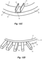
- the protective element takes the form of a planar element that is a plate 35 that is inclined relative to the annular disc body 20.
- the plate 35 is inclined forward toward the direction of rotation 37 of the grinding disc 12.
- the plate 35 is inclined away from the direction of rotation 37 of the grinding disc 12.
- the planar element could take other forms other than the plate 25, such as a vane, a blade, a fin, or any other planar element.
- the protective element takes the form of a channel 40 having two walls 42, 45 extending orthogonally to a base 48 mounted to the planar surface 21 of the annular disc body 20.
- the protective elements take the form of rectangular posts 50 extending radially from the outer edge 23 of the annual disc body 20.
- the posts 50 can be cylindrical (i.e. a rod), hexagonal, oval or any other polygonal shape.
- one of the protective elements takes the form of cylindrical posts or rods 55 extending substantially orthogonally from the planar surface 21 of the annular disc body 20.
- the rods 55 are aligned to be orthogonal to the outer edge 23.
- the posts 55 need not be in alignment or be aligned but at an angle to the outer edge 23.
- Another of the protective elements takes the form of a ramp 60 having inclined sides 62, 63 and mounted to the planar surface 21 at its base 64.
- One protective element takes the form of a depression or recess 65, which is concave in shape in this embodiment.
- the depression or recess 65 need not be concave, but could take other shapes, such as oval, rectangular or even irregular shapes.
- the inventors consider that the depression 75 acts to capture or trap the grinding media M so as to promote grinding within the grinding media population, rather than causing grinding in the zone between the grinding media M and grinding discs 12.
- Another protective element takes the form of a an inverted triangular prism or ramp 70 having inclined sides 72, 73, both extending substantially orthogonally from the planar surface 21 of the annular disc body 20.
- the third protective element takes the form of a sinuous or curved planar element 74 that extends substantially orthogonally from the planar surface 21 of the annular disc body 20.
- Figure 12G shows yet another embodiment of the protective element that takes the form of an angle or bracket 80 with a single wall 82 connected to a base 85 mounted to the planar surface 21 of the annular disc body.
- protective elements 35, 40, 55, 60, 65, 70, 74, 75, 80 can also extend from the other planar surface 22, either in addition to or as an alternative to the protective elements extending from the planar surface 21. They may also extend radially from the outer edge 23 instead of or in addition to the planar surface 21.
- the protective elements 25, 40, 55, 74, 80 extend substantially orthogonally from the planar surfaces 21, 22, these protective elements can extend at an angle to the planar surfaces 21, 22 in similar fashion to the embodiment shown in Figures 12A and 12B .
- the protective elements 25, 40, 55, 60, 70, 74, 80 can be mounted at an angle to the outer edge 23 instead of being tangentially at right angles as illustrated in Figures 9 to 11 and 12A to 12G .
- the radial posts 50 may also extend at an angle from the outer edge 23 instead of radially outward.
- FIGS 13A to 13E Yet further configurations for the stirring devices 12 are illustrated in Figures 13A to 13E . These configurations are not encompassed by the wording of the claims but are considered as useful for understanding the invention.
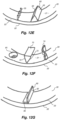
- Figure 13A there are blocks or rectangular prism-shaped flanges 88, 89 that extend from the opposed surfaces of the body 12. The flanges 88, 89 alternate in position so that a flange 89 extending from the lower surface 22 is between flanges 88 extending from the upper surface 21, and vice-versa.
- the stirring device 12 comprises a corrugated body with upper corrugations 90 and lower corrugations 92 that form its protective elements. It will be appreciated that while the corrugations are rectangular, they may be in other forms, such as curved or triangular corrugations.
- the stirring device 12 comprises a body formed from radially extending rectangular posts or beams 94, 95 that are offset to one another, so that the beams 94 are above the beams 95. This creates protective elements from the upper beams 94 and the lower beams 95.
- Figure 13D illustrates an embodiment not covered by the subject-matter of the claims, where the protective elements are employed directly to protect the drive shaft 11 while acting as stirring devices.
- a series of plates 97 project directly from the drive shaft 11 to create protective elements that deflect the slurry particles and grinding media M from the drive shaft.
- the plates 97 also rotate the feed slurry to promote grinding of the slurry particles by the grinding media M.
- the plates 97 ensure that grinding occurs in the cavity 15, away from the surfaces of the drive shaft 11, thus minimising wear on the mill body components.
- Figure 13E shows a stirring device 12 that has a saw-tooth configuration with alternating peaks 99 and valleys 100 integrated into its body, so as to form ramp-like deflection surfaces 102 that act as the protective elements.
- the invention can be implemented in relation to the mill body 2 rather than the mill impeller 10.
- the invention takes an opposite configuration for the mill body 2 by providing the protective elements 25 on the shelves 14 on the inner sidewalls 13 instead of on the grinding discs 12 so as to deflect the slurry particles and grinding media M from the shelves 14 and inner sidewalls 13. This enables a zone to be created around the shelves 14 and inner sidewalls 13, minimising wear on these components of the mill body 2.
- the blocks 25 are spaced apart around the annular shelf 14 in proximity to the now fully planar annular grinding discs 112 and as the annular shelves 14 are interposed between the grinding discs 12 a zone is created around the outer edges 23 of the grinding discs and part of the opposed planar surfaces 21, 22.
- the protective elements in this alternative configuration are not limited to the blocks 25, but can include the many variants described above, especially in relation to Figures 12A to 12G and 13A to 13E .
- This "static" configuration for the blocks 25 is sufficient to achieve the above stated technical advantages and benefits of the invention.
- protective elements 25 can be provided on the inner sidewall 13 between the shelves 14 opposite the grinding discs 12 to further minimise wear.
- Yet another embodiment has angled annular shelves 14 instead of being orthogonal to the inner sidewall 13 that extend radially inward.
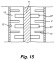
- the protective elements 25 are provided on the drive shaft 11 of the mill impeller to further enhance the zone created around the grinding discs 12.
- the protective elements 25 in this embodiment are axially aligned with the longitudinal axis 6 of the drive shaft 11 and may be located on annular shelves or discs similar to the mounting ring 28 and/or directly on the drive shaft.
- Figure 15 shows one variation of this embodiment, using the configuration of Figure 13D , in which the plates 97 are mounted or connected directly to the drive shaft 11.
- the protective elements are not limited to the blocks 25, but can include the many variants described above, especially in relation to Figures 12A to 12G and Figures 13A to 13C and 13E .
- the invention may also be used in other mill types, such as grinding mills having a horizontally arranged or an angled mill body.
- the invention has also been developed for use with high intensity grinding mills that are grinding fine particulates, but is also equally applicable to other grinding mills of the type that use stationary mill shells with rotating stirring elements.
- the invention is readily applicable to various types of particulate material having a variety of particle sizes and particle size distributions.
- Particle size is usually measured at the feed and at the discharge outlet.
- the particle size of the slurry at the feed inlet is typically measured as F80, meaning that 80% of the feed particles pass through a nominated screen mesh size.
- F80 100 ⁇ m means that 80% of all particles present will pass through a 100 ⁇ m screen aperture.
- F100 meaning that 100% of the feed particles pass through a nominated screen mesh size.
- P80 means that 80% of the particles pass through a nominated screen mesh size.
- the invention is readily applicable to many different types of particulate materials and is not limited to particular mineral ore types, but can include iron, quartz, copper, nickel, zinc, lead, gold, silver and platinum.
- Other particulate materials that can be processed using the invention include concrete, cement, recyclable materials (such as glass, ceramics, electronics and metals), food, paint pigment, abrasives and pharmaceutical substances.
- the invention is used to reduce the size of the particulate material using a grinding process.
- any of the features in the preferred embodiments of the invention can be combined together and are not necessarily applied in isolation from each other.
- different types of protective elements can be used on the same mill impeller, such as shown in Figures 12F and 12G .
- the protective elements 25 (or its many variants as described above and in particular with reference to Figures 12A to 12G and 13A to 13E ) can be used on both the grinding discs 12 and the shelves 14 together, instead of being exclusive of each other.
- some parts of the mill body 2 only have grinding discs 12 with the protective elements 25 while other parts of the mill body 2 only have shelves 14 with the protective elements 25.
- the protective elements 25 of the grinding discs 12 may act as a skeleton for coating with a dissimilar material that forms a sacrificial protective layer arranged to wear off and expose the protective elements within a very short period of time after the installation and start of the grinding operation.
- the sacrificial protective material may sometimes be used for manufacturing, shipping and installing purposes.
- the invention By providing protective elements on the stirring devices, shaft assembly or shelves of the mill body to create a zone, the invention reduces the amount of wear and thus prolongs the operational life of the components of the grinding mill, reducing maintenance time, costs and improving efficiency of the grinding mill.
- the zone generated by the protective elements also promotes slurry particle contact with the grinding media, also improving grinding efficiency.
- the grinding mill is able to operate more efficiently, consuming components such as grinding discs as at lower rate while grinding at faster rates.
- the invention when implemented in a mill impeller can be readily retrofitted in existing fine grinding mills. In all these respects, the invention represents a practical and commercially significant improvement over the prior art.
Description
- The invention relates to improvements in grinding mills and in particular to a stirring device for a grinding mill, stirring device assembly, mill body, grinding mill and method for grinding particulate material. The invention has been developed primarily for use in a fine grinding mill for grinding mineral ore particles. However, it will be appreciated that the invention is applicable in the grinding of other particulate material, such as concrete, cement, recyclable materials (such as glass, ceramics, electronics and metals), food, paint pigments, abrasives and pharmaceutical substances.
- Grinding mills are typically used in mineral processing to grind mineral ore particles into smaller sized particles to facilitate further downstream processing, such as separation of the valuable mineral particles from unwanted gangue. One type of grinding mill is a fine grinding mill for grinding mineral ore particles in the range of about 30µm to 4000µm in diameter down to particles of 5 to 40µm in diameter. As fine grinding mills consume a large amount of power per tonne of ore processed, they are typically used on a concentrate stream comprising mostly of a high-grade mineral ore that has already been ground using a ball or SAG type grinding mill that performs coarse grinding as it is more economic.
- The fine grinding mill has a stationary mill body or shell arranged vertically in the mill and an internal drive shaft. The drive shaft has a plurality of stirring elements, such as grinding discs, so that rotation of the drive shaft also rotates the stirring elements, which in turn rotates or stirs the mineral ore particles, usually in the form of a feed slurry, with a suitable grinding media. The resulting stirring action causes the mineral ore particles to be ground into smaller sized particles. However, the grinding discs tend to suffer from excessive wear, especially when the grinding mill is operated at high speeds through the action of the harder grinding media impacting against the grinding discs.
US-6158680-A discloses an example of a grinding mill comprising stirring elements. The mill disclosed inUS-3307792-A comprises additionally shelves extending from an inner sidewall. - According to the invention, there is provided a stirring device defined in
claim 1 and a mill body defined inclaim 11. - A first aspect of the present invention provides a stirring device for stirring a particulate material and a grinding media in a grinding mill, comprising one or more protective elements that extend outwardly from a body to deflect said particulate material and said grinding media from said body.
- Preferably, said one or more protective elements comprise a deflection surface, said deflection surface being arranged at an angle to a direction of rotation of said body. More preferably, said deflection surface is at an angle in the range of 10° to 170°, preferably 20° to 160°, preferably 30° to 150°, preferably 40° to 130°, preferably 50° to 120°, preferably 60° to 110°, more preferably 70° to 100°, even more preferably 80° to 95°, and most preferably 85° to 90°. In one embodiment, said deflection surface is orthogonal to the direction of rotation of said body.
- Preferably, said one or more protective elements extend at an angle to a surface of said body. More preferably, said angle is in the range of 10° to 170°, preferably 20° to 160°, preferably 30° to 150°, preferably 40° to 130°, preferably 50° to 120°, preferably 60° to 110°, more preferably 70° to 100°, even more preferably 80° to 95°, and most preferably 85° to 90°. In one embodiment, said one or more protective elements extend orthogonally from said surface. In some embodiments, said body surface is a planar surface. In other embodiments, said body surface is a non-planar surface.
- According to the first aspect, said body comprises an outer edge, wherein said one or more protective elements extend from said outer edge. More particularly, said one or more protective elements extend radially from said outer edge.
- According to the first aspect, said body comprises opposed surfaces and said one or more protective elements extend from at least one of said opposed surfaces. More particularly, said one of more protective elements extend from each of said opposed surfaces.
- According to the first aspect, there is a plurality of said protective elements, said protective elements being spaced apart around said body. Preferably, said protective elements are spaced apart at regular intervals. In one embodiment, said protective elements are spaced apart at irregular or uneven intervals. In a further embodiment, some of said protective elements are spaced apart at regular intervals on one portion of said body and other of said protective elements are spaced apart at irregular intervals on another portion of said body.
- Preferably, said body comprises an annular shape. According to the first aspect, said body comprises an annular disc. Preferably, said opposed surfaces are planar surfaces. In one embodiment, said outer edge is an outer circumferential edge of said annular disc. In some embodiments, said annular disc has a diameter in the range of 250mm to 3000mm, preferably 300mm to 2750mm and most preferably 400mm to 2500mm.
- The one or more protective elements can be configured into different shapes. Preferably, said one of more protective elements each comprise at least one or more of a projection, an elongated body, a block-shaped element, a flange, a tooth, a planar element, a vane, a blade, a fin, a plate, a bar, a post, a rod, a channel-shaped element, a V-shaped element, a U-shaped element, a depression, a recess, a ramp-like element and a wedge-shaped element.
- Preferably, said one or more protective elements are substantially linear in shape. Alternatively, one or more protective elements have a non-linear configuration. For example, the protective element(s) may be helical, spiral, sinuous or curved, in whole or part.
- Where said one or more protective elements comprise said block-shaped element, said block-shaped element is preferably connected to said planar body so that opposed sides of said block-shaped element extend outwardly from said opposed surfaces of said planar body. In one embodiment, said block-shaped element comprises an outer end that extends radially outwardly from an outer edge of said planar body. In some embodiments, said block-shaped element is integrally forms with said planar body. In other embodiments, said block-shaped element is U-shaped for mounting to said planar body.
- Preferably, where said one or more protective elements comprise said planar element, said planar element is inclined relative to the said planar body. In one embodiment, said planar element is inclined towards a direction of rotation of said stirring device. In another embodiment, said planar element is inclined away from a direction of rotation of said stirring device.
- Preferably, said planar element comprises a vane, blade, planar tooth or plate.
- Preferably, said one or more protective elements are integrally formed with said body.
- A second aspect of the present invention provides the use of the stirring device of the first aspect of the invention in a stirring device assembly.
- A third aspect of the present invention provides a stirring device assembly for stirring a particulate material and a grinding media in a grinding mill, comprising a plurality of stirring devices of the first aspect of the invention mounted to a drive shaft for rotating said stirring devices.
- Preferably, said stirring devices are spaced apart along the length of said drive shaft.
- Preferably, said drive shaft comprises one or more of protective elements extending radially from said drive shaft. More preferably, said protective elements have the same features as the preferred features of the one or more protective elements of the first aspect of the invention.
- A fourth aspect of the present invention provides the use of the stirring device assembly of the third aspect of the invention as a mill impeller in a grinding mill.
- A fifth aspect of the present invention provides a drive shaft assembly for stirring a particulate material and a grinding media in a grinding mill, comprising a drive shaft and a plurality of protective elements for deflecting said particulate material and said grinding media from said drive shaft.
- Preferably, said protective elements are spaced apart along the length of said drive shaft.
- Preferably, at least two of said protective elements extend from either side of said drive shaft. In one embodiment, said protective elements extend radially outwardly from said drive shaft. In some embodiments, said protective elements are arranged around the circumference of said drive shaft.
- Preferably, said protective elements have the same features as the preferred features of the protective elements of the first aspect of the invention, where applicable. For example, the protective elements also preferably have a deflection surface as in the first aspect of the invention, but which is arranged at angle to the direction of rotation of the drive shaft and not a stirring device body. In this case, the preferred ranges of the angle are the same, including providing the deflection surface substantially orthogonal to the direction of rotation of the drive shaft. Likewise, the protective elements may also extend at an angle, but with respect to the direction of rotation of the drive shaft and not a stirring device body. In one particularly preferred embodiment, said protective elements have a planar or non-curved deflection surface.
- A sixth aspect of the present invention provides the use of the drive shaft assembly of the fourth aspect of the invention as a mill impeller in a grinding mill.
- A seventh aspect of the present invention provides a mill body comprising the stirring device assembly of the third aspect of the invention or the drive shaft assembly of the fourth aspect of the invention.
- Preferably, said mill body further comprises an inlet for receiving a particulate material and an outlet for discharging ground particles.
- Preferably, said mill body comprises one or more shelves extending from an inner sidewall, said one or more shelves define one or more chambers containing said stirring devices or said protective elements, and openings communicating between said chambers.
- Preferably, said one or more shelves alternate between said one or more stirring devices or said protective elements.
- Preferably, said mill body is arranged vertically in said mill. In some embodiments, said mill body is arranged at an angle in said mill. In other embodiments, said mill body is arranged horizontally in said mill.
- Preferably, said inlet is at the bottom of said mill body and said inlet is at the top of said mill body.
- An eighth aspect of the present invention provides a grinding mill comprising the mill body of the seventh aspect of the invention.
- Preferably, said grinding mill is a fine grinding mill. More preferably, said fine grinding mill has a power consumption of 10 to 70 kilowatt hours per tonne (kWhr/t). In one preferred embodiment, said fine grinding mill has a power consumption of 30kWhr/t.
- A ninth aspect of the present invention provides a mill body for grinding a particulate material comprising an inlet for receiving said particulate material, an outlet for discharging ground particles and a shelf extending from an inner sidewall, said shelf comprising one or more protective elements that extend outwardly from said shelf to deflect said particulate material and said grinding media said shelf.
- According to the ninth aspect, said one or more protective elements extend radially from said shelf.
- According to the ninth aspect, said shelf comprises opposed surfaces and said one or more protective elements extend from at least one of said opposed surfaces. More particularly, said one of more protective elements extend from each of said opposed surfaces.
- Preferably, said one or more protective elements extend orthogonally from at least one of said opposed surfaces. More preferably, said one or more protective elements extend orthogonally from each of said opposed surfaces.
- According to the ninth aspect, there is a plurality of said protective elements, said protective elements being spaced apart around said shelf. In one embodiment, said protective elements are spaced apart at regular intervals. In another embodiment, said protective elements are spaced apart at uneven or regular intervals.
- Preferably, said one or more protective elements of the sixth aspect have the same features as the preferred features of the one or more protective elements of the first aspect of the present invention, where applicable.
- Preferably, said shelf is annular in shape. In some embodiments, said shelf is angled relative to the inner sidewall. In other embodiments, said shelf is a static counter disc.
- A tenth aspect of present invention provides a grinding mill comprising the mill body of the ninth aspect of the invention, a drive shaft and a plurality of stirring elements mounted to said drive shaft.
- Preferably, the grinding mill of the ninth aspect has the preferred features of the eighth aspect of the invention, where applicable.
- An eleventh aspect of the present invention provides a method of grinding a particulate material in a grinding mill of the type having a mill body and a drive shaft for rotating a plurality of stirring devices within said mill body, said method comprising:
- introducing grinding media into said mill body;
- introducing said particulate material through an inlet; and
- operating said drive shaft to rotate said stirring devices within said mill body;
- wherein said rotation of said stirring devices induces a rotating flow of said particulate material within said mill body to grind said particulate material against said grinding media to produce smaller sized particles; and
- wherein one or more protective elements deflect said particulate material and said grinding media away from said stirring devices.
- Preferably, said method comprises creating a zone around said stirring devices where said grinding media is captured by said one or more protective elements and rotated with said stirring devices.
- Preferably, said method comprises arranging said one or more protective elements at an angle to a direction of rotation of said stirring devices.
- Preferably, said one or more protective elements comprise a deflection surface, said method comprising arranging said deflection surface at an angle to a direction of rotation of said stirring devices.
- Preferably, said angle is in the range of 10° to 170°, preferably 20° to 160°, preferably 30° to 150°, preferably 40° to 130°, preferably 50° to 120°, preferably 60° to 110°, more preferably 70° to 100°, even more preferably 80° to 95°, and most preferably 85° to 90°. In one embodiment, said method comprising arranging said deflection surface orthogonally to the direction of rotation.
- Preferably, said method comprises locating said one or more protective elements adjacent said stirring devices. In some embodiments, said one or more protective elements extend from said stirring devices. In other embodiments, said one or more protective elements extend from a shelf extending from an inner sidewall of said mill body.
- A twelfth aspect of the present invention provides a method of grinding a particulate material in the grinding mill of the type having a mill body and a drive shaft assembly comprising a plurality of protective elements extending from a drive shaft, said method comprising:
- introducing grinding media into said mill body;
- introducing said particulate material through an inlet; and
- operating said drive shaft to rotate said drive shaft assembly within said mill body;
- wherein said rotation of said drive shaft assembly induces a rotating flow of said particulate material within said mill body to grind said particulate material against said grinding media to produce smaller sized mineral particles; and
- wherein said protective elements deflect said particulate material and said grinding media away from said drive shaft.
- Preferably, said particulate material comprises mineral particles. More preferably, said mineral particles have a F80 of 30µm to 4000µm, preferably 35µm to 3000µm, preferably 40µm to 2000µm, preferably 45µm to 1500µm, even more preferably 50µm to 1000µm, preferably 60µm to 750µm, further preferably 65µm to 500µm, further more preferably 70µm to 400µm, even more preferably 75µm to 300µm and most preferably 80µm to 200µm.
- Preferably, wherein said smaller sized mineral particles have a P80 of 0.1 µm to 1000µm, preferably 0.25µm to 750µm, preferably 0.3µm to 500µm, preferably 0.4µm to 400µm, preferably 0.5µm to 300µm, preferably 0.6µm to 250µm, preferably 0.7µm to 200µm further preferably 0.75µm to 150µm, further more preferably 0.8µm to 100µm, even more preferably 0.9µm to 75µm and most preferably 1µm to 50µm.
- Preferably, wherein said particulate material comprises mineral particles. More preferably, said mineral particles are mineral ore particles having a density of at least 2,000 kg/m3. In some embodiments, said mineral ore particles comprises at least one of iron, quartz, copper, nickel, zinc, lead, gold, silver, platinum, tungsten, chromium, silicon and combinations thereof.
- Preferably, said particulate material comprises at least one of concrete, cement, recyclable material, pharmaceutical substances, paint pigment, abrasives and food. In some embodiments, said recyclable material comprises at least one of glass, ceramics, electronics and metals.
- The methods of the tenth and eleventh aspects of the invention have the preferred features of any previous aspect of the invention, where applicable. In particular, said protective elements have the preferred features of the first aspect of the invention, where applicable.
- Unless the context clearly requires otherwise, throughout the description and the claims, the words "comprise", "comprising", and the like are to be construed in an inclusive sense as opposed to an exclusive or exhaustive sense; that is to say, in the sense of "including, but not limited to".
- Furthermore, as used herein and unless otherwise specified, the use of the ordinal adjectives "first", "second", "third", etc., to describe a common object, merely indicate that different instances of like objects are being referred to, and are not intended to imply that the objects so described must be in a given sequence, either temporally, spatially, in ranking, or in any other manner.
- Preferred embodiments of the invention will now be described, by way of example only, with reference to the accompanying drawings in which:
-
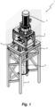
Figure 1 is a perspective view of a grinding mill having a stirring device assembly comprising a plurality of stirring devices according to an embodiment of the invention; -
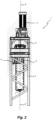
Figure 2 is a front view of the grinding mill ofFigure 1 ; -
Figure 3 is a side view of the grinding mill ofFigure 1 ; -
Figure 4 is a rear view of the mill body used in the grinding mill ofFigure 1 ; -
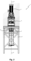
Figure 5 is a cross-sectional view of the mill body ofFigure 4 ; -
Figure 6 is a partial cross-sectional perspective view of the mill body ofFigure 4 ; -
Figure 7 is a partial cross-sectional view of the mill body ofFigure 4 at the mounting ring indicated by area A inFigure 5 ; -
Figure 8 is a top view of the mill body ofFigure 4 ; -
Figure 9 is a perspective view of a stirring device in the stirring device assembly used in the mill body ofFigure 1 ; -
Figure 10 is a side view of the stirring device ofFigure 9 ; -
Figure 11 is a cross-sectional view of the stirring device ofFigure 9 ; -
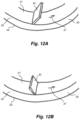
Figures 12A to 12G are partial perspective views of stirring devices according to other embodiments of the invention; -
Figures 13A to 13E are partial perspective views of stirring devices and drive shaft assemblies not forming part of the invention; -
Figure 14 is a partial cross-sectional view of a mill body according to another embodiment of the invention; and -
Figure 15 is a partial cross-sectional view of a mill body according to another embodiment of the invention. - The present invention will now be described with reference to the following examples which should be considered in all respects as illustrative and non-restrictive. In the Figures, corresponding features within the same embodiment or common to different embodiments have been given the same reference numerals. Referring to
Figures 1 to 3 , a grindingmill 1 for grinding a slurry having particulate material comprises amill body 2 mounted on abase frame 3 and adrive mechanism 4 mounted on adrive frame 5 for rotating themill body 3 about alongitudinal axis 6. - In this embodiment, the
mill body 2 is arranged vertically in the grindingmill 1 and has abottom inlet 7 and atop outlet 8. It will be appreciated that in other embodiments, themill body 2 is arranged to be inclined or at an angle in the grindingmill 1. In some embodiments, themill body 2 is arranged to lie horizontally in the grindingmill 1. Likewise, in other embodiments, the inlet 7a andoutlet 8 can be placed at locations of themill body 2 other than the bottom and top, respectively. - A charge of feed slurry comprising mineral ore particles is fed into the
mill body 2 through thebottom inlet 7. Grinding media M is also added into themill body 2 initially through theoutlet 8 before the feed slurry is added and grindingmill 1 is in operation. Once the grindingmill 1 is in operation, the initial charge of grinding media M tends to wear out due to the grinding process. Accordingly, grinding media M is also progressively added with the feed slurry through theinlet 7 as the grindingmill 1 operates. The grinding media M typically comprises ceramic or steel beads that range from 1mm to 5mm in diameter. The size of the grinding media M may vary in other embodiments, depending on requirements. For example, the diameter of the grinding media can be 30 or 50 times the diameter of the slurry particles, which can be measured by reference to F80 or F100, which is discussed in more detail below. Themill body 2 is rotated by thedrive mechanism 4 about theaxis 6 to rotate or stir the feed slurry and grinding media together, causing the feed slurry particles to be crushed or ground against between the grinding media. The ground product is then discharged through thetop outlet 8. - Referring to
Figures 4 to 8 , themill body 2 comprises a mountingassembly 9 for fitting the mill body to thebase frame 3 and operatively aligning the mill body to thedrive mechanism 4. The mountingassembly 9 comprises asupport gusset 9a and a mountinghinge 9b. Themill body 2 also comprises a stirringdevice assembly 10 comprising adrive shaft 11 to which are mounted a plurality of stirringdevices 12 described in more detail below. In this embodiment, the stirringdevice assembly 10 takes the form of an impeller, but is also known as a drive shaft assembly. As such, the stirring device assembly will hereinafter be referred to as a mill impeller in reference to this embodiment. - An
internal side wall 13 of themill body 2 has a plurality of planarannular shelves 14 extending into theinternal cavity 15 between the stirringdevices 12 to subdivide themill body 2 so that the feed slurry flows upwardly from thebottom inlet 7 throughopenings 16 and eventually is discharged from thetop outlet 8 after grinding. Theshelves 14 tend to subdivide theinternal cavity 15 intoindividual chambers 17. In this embodiment, the grindingmill 1 is a fine grinding mill, and is called a high intensity grinding mill, in which the rotating action of the stirringdevices 12 results in intense grinding of the slurry particles by the grinding media M occurring in thecavity 15 adjacent the stirring devices. Fine grinding mills have a relatively high power consumption in order to achieve fine grinding, in the range from 10 kWhr/t to 70 kWhr/t (kilowatt hours per tonne). In this embodiment, the fine grinding mill has a power consumption of 30 kWhr/t. - Referring to
Figures 9 to 11 , the stirringdevices 12 in themill impeller 10 comprise aplanar body 20 having opposedplanar surfaces outer edge 23. In this embodiment, theplanar body 20 is an annular disc but it will be appreciated that the planar body can take other forms in other embodiments, such as rectangular, square, oval or oval-like, circular and any other regular or irregular polygonal shape. It will be appreciated by one skilled in the art that for industrial duties the annular disc size ranges from 400mm diameter to 2500mm diameter. However, the invention applies equally to fine grinding discs of any size. Also, the stirringdevices 12 can have surfaces other than two opposed surfaces, such as any number of surfaces that have the same or different shapes. For example, the stirring devices may have an inclined or angled surface, a curved surface, a corrugated surface, a saw-toothed surface, irregular surface or any other regular or irregular shape. For ease of reference, the stirringdevices 12 andplanar body 20 in this embodiment will hereinafter be referred to as grinding discs and disc body, respectively. - A plurality of
protective elements 25 adjacent to theouter edge 23 extends outwardly from thedisc body 20 to deflect the slurry particles and grinding media M. This effectively minimises or reduces the shear around thedisc body 20 by minimising contact of the mixture of slurry particles and grinding media M against thedisc body 20 and promoting contact between the slurry particles and grinding media. A mountingring 28 is connected via arms 29 (typically known as spokes) to thedisc body 20 for mounting each grindingdisc 12 to thedrive shaft 11 of the stirringdevice assembly 11. Theprotective elements 25 in this embodiment take the form of blocks or block-like elements that are integrally formed with thedisc body 20 and arranged so thatopposed sides end 33 of the blocks project outwardly from theplanar surfaces outer edge 23, respectively. Eachblock 25 thus extends both substantially orthogonally relative to the opposedplanar surfaces opposed sides outer edge 23 via itsend 33. Alternatively, theprotective elements 25 are in the form of U-shaped blocks mounted to thedisc body 20 so thatopposed sides end 33 of eachblock 25 extends or projects outwardly from theplanar surfaces outer edge 23 of the disc body, respectively. - In operation, the
drive mechanism 4 rotates thedrive shaft 11 of the stirringdevice assembly 10, rotating the grindingdiscs 12 that in turn rotate the feed slurry and grinding media within theinternal cavity 15 of themill body 2. This rotation causes the feed slurry particles to be ground against and between the harder grinding media, thus releasing valuable mineral particles and reducing them in size for further downstream processing after being discharged through theoutlet 8. The feed slurry particles may also be ground against themill impeller 10. This grinding action occurs over a period of time and thus can be viewed as attrition of the slurry particles. In addition, theblocks 25 act to create a zone (relative to the motion of the grinding disc 12) around the outercircumferential edges 23 and the opposed surfaces 21, 22 of thedisc body 20, promoting contact between the feed slurry particles and the grinding media M. In effect, a rotating pocket of material comprising the feed slurry and grinding media M is formed and "captured" in the zone that can be transported by theblocks 25. At the same time, the zone created by theblocks 25 minimises the amount of shear or slippage at thesurfaces discs 12, thus reducing the amount of wear on the grindingdiscs 12. That is, theprotective elements 25 tend to move the slurry and the grinding media M away from the grindingdiscs 12. This means that there is less chance of shear or slippage being concentrated at the grindingdiscs 12. In addition, there is a lower probability of impacts occurring between the grinding media M and the grindingdiscs 12, and any impacts that do occur are not substantial but only minor in nature. Hence, the grindingdiscs 12 do not suffer excessive wear during operation of themill body 2 in the grindingmill 1. - It is known by those skilled in the art that concentrated mineral ore slurries frequently act as non-Newtonian (shear thinning) fluids with a yield stress. This means that such slurries tend to act as a solid body and do not act as a fluid until sufficient force is applied (exceeding the yield stress), after which the viscosity drops dramatically. As a consequence, in a conventional grinding mill of the type that uses a series of stirring elements like grinding discs, the highest shear force is applied by the rotational torque at the lowest radius from the rotational centre due to the geometry of the rotating discs and drive shaft. This results in the non-Newtonian slurry material yielding and becoming fluid immediately adjacent to the drive shaft and grinding discs, with the rest of the slurry material remaining stationary, or close to stationary. This results in the shear or "slip" being concentrated right at the surface of the grinding discs, accelerating the amount of wear to the grinding discs. Accelerated wear of the grinding discs makes their operational life very short, thus requiring more frequent replacement than desired. The frequent replacement of the grinding discs also increases the amount of downtime, reducing the efficiency of the grinding mill, as well as increasing maintenance costs.
- From this description of conventional fine grinding mills using stirring elements, the technical advantages and benefits of the invention become apparent by way of contrast. In the embodiment of the invention, the zone around the
outer edge 23 and theplanar surfaces blocks 25 alleviates or overcomes the above drawbacks and deficiencies that occur in conventional grinding mills. That is, the zone minimises or reduces the amount of wear on the grindingdiscs 12 by minimising the differential speed between the grinding media M and the grinding discs 12 (i.e. the amount of shear), prolonging their operational life. Consequently, there is less frequent replacement of the grindingdiscs 12, thus reducing maintenance costs and increasing grinding mill capacity due to there being less downtime for maintenance. By improving the amount or frequency of contact between the feed slurry particles and the grinding media M, the zone improves the efficiency of grinding in the grindingmill 1. Furthermore, the zone increases the amount of the feed slurry that acts as a fluid. - It will be appreciated that the
protective elements 25 can take any number of forms in order to create the zone around each grindingdisc 12. Theprotective elements 25 can be any form of projection that extends from the surfaces of the grindingdisc 12, such as the upperplanar surface 21, the lowerplanar surface 22, itsouter edge 23 or any combination thereof. Theprotective element 25 can thus be planar, curved or adopt any polyhedral shape that protrudes for generating the zone. Some examples of possible shapes for theprotective element 25 are illustrated inFigures 12A to 12G ,13A to 13E and discussed in more detail below. Aside from these specific examples, theprotective elements 25 may comprise at least one or more of a protrusion, an elongated body, a flange, a tooth, a vane, a blade, a fin, a bar, a V-shaped element, a U-shaped element and a wedge-shaped element. However, it is preferred that the protective elements either extend or present a deflection surface that is at an angle so that they can gather or grip the slurry particles and grinding media M to deflect or move them away from the stirring device body. Hence, the most preferred implementation is to provideprotective elements 25 that are orthogonal (i.e. 90°) to the direction of rotation of the stirringdevice 12 or slurry within thecavity 15. - Referring to
Figures 12A and 12B , the protective element takes the form of a planar element that is aplate 35 that is inclined relative to theannular disc body 20. InFigure 12A , theplate 35 is inclined forward toward the direction ofrotation 37 of the grindingdisc 12. InFigure 12B , theplate 35 is inclined away from the direction ofrotation 37 of the grindingdisc 12. It will be appreciated that the planar element could take other forms other than theplate 25, such as a vane, a blade, a fin, or any other planar element. - In
Figure 12C , the protective element takes the form of achannel 40 having twowalls planar surface 21 of theannular disc body 20. InFigure 12D , the protective elements take the form ofrectangular posts 50 extending radially from theouter edge 23 of theannual disc body 20. In other variations of this embodiment, theposts 50 can be cylindrical (i.e. a rod), hexagonal, oval or any other polygonal shape. - In
Figure 12E , one of the protective elements takes the form of cylindrical posts orrods 55 extending substantially orthogonally from theplanar surface 21 of theannular disc body 20. In this embodiment, therods 55 are aligned to be orthogonal to theouter edge 23. However, it will be appreciated that in other embodiments, theposts 55 need not be in alignment or be aligned but at an angle to theouter edge 23. Another of the protective elements takes the form of aramp 60 having inclinedsides planar surface 21 at its base 64. - Three different embodiments of the protective elements are illustrated in
Figure 12F . One protective element takes the form of a depression orrecess 65, which is concave in shape in this embodiment. In other forms, the depression orrecess 65 need not be concave, but could take other shapes, such as oval, rectangular or even irregular shapes. The inventors consider that the depression 75 acts to capture or trap the grinding media M so as to promote grinding within the grinding media population, rather than causing grinding in the zone between the grinding media M and grindingdiscs 12. Another protective element takes the form of a an inverted triangular prism or ramp 70 having inclinedsides planar surface 21 of theannular disc body 20. The third protective element takes the form of a sinuous or curvedplanar element 74 that extends substantially orthogonally from theplanar surface 21 of theannular disc body 20.Figure 12G shows yet another embodiment of the protective element that takes the form of an angle orbracket 80 with asingle wall 82 connected to a base 85 mounted to theplanar surface 21 of the annular disc body. - While the protective elements illustrated in
Figures 12A to 12C and12E to 12G all extend from theplanar surface 21, it will be appreciated that the illustratedprotective elements planar surface 22, either in addition to or as an alternative to the protective elements extending from theplanar surface 21. They may also extend radially from theouter edge 23 instead of or in addition to theplanar surface 21. - Furthermore, while the
protective elements planar surfaces planar surfaces Figures 12A and 12B . Also, theprotective elements outer edge 23 instead of being tangentially at right angles as illustrated inFigures 9 to 11 and12A to 12G . The radial posts 50 may also extend at an angle from theouter edge 23 instead of radially outward. - Yet further configurations for the stirring
devices 12 are illustrated inFigures 13A to 13E . These configurations are not encompassed by the wording of the claims but are considered as useful for understanding the invention. InFigure 13A , there are blocks or rectangular prism-shapedflanges body 12. Theflanges flange 89 extending from thelower surface 22 is betweenflanges 88 extending from theupper surface 21, and vice-versa. - In
Figure 13B , the stirringdevice 12 comprises a corrugated body withupper corrugations 90 andlower corrugations 92 that form its protective elements. It will be appreciated that while the corrugations are rectangular, they may be in other forms, such as curved or triangular corrugations. - In
Figure 13C , the stirringdevice 12 comprises a body formed from radially extending rectangular posts or beams 94, 95 that are offset to one another, so that thebeams 94 are above thebeams 95. This creates protective elements from theupper beams 94 and the lower beams 95. -
Figure 13D illustrates an embodiment not covered by the subject-matter of the claims, where the protective elements are employed directly to protect thedrive shaft 11 while acting as stirring devices. A series ofplates 97 project directly from thedrive shaft 11 to create protective elements that deflect the slurry particles and grinding media M from the drive shaft. Theplates 97 also rotate the feed slurry to promote grinding of the slurry particles by the grinding media M. In this particular embodiment, theplates 97 ensure that grinding occurs in thecavity 15, away from the surfaces of thedrive shaft 11, thus minimising wear on the mill body components. -
Figure 13E shows a stirringdevice 12 that has a saw-tooth configuration with alternatingpeaks 99 andvalleys 100 integrated into its body, so as to form ramp-like deflection surfaces 102 that act as the protective elements. - It is contemplated in a further aspect that the invention can be implemented in relation to the
mill body 2 rather than themill impeller 10. In this aspect, the invention takes an opposite configuration for themill body 2 by providing theprotective elements 25 on theshelves 14 on theinner sidewalls 13 instead of on the grindingdiscs 12 so as to deflect the slurry particles and grinding media M from theshelves 14 andinner sidewalls 13. This enables a zone to be created around theshelves 14 andinner sidewalls 13, minimising wear on these components of themill body 2. In this alternative configuration, as best shown inFigure 14 , theblocks 25 are spaced apart around theannular shelf 14 in proximity to the now fully planar annulargrinding discs 112 and as theannular shelves 14 are interposed between the grinding discs 12 a zone is created around theouter edges 23 of the grinding discs and part of the opposedplanar surfaces blocks 25, but can include the many variants described above, especially in relation toFigures 12A to 12G and13A to 13E . This "static" configuration for theblocks 25 is sufficient to achieve the above stated technical advantages and benefits of the invention. In a further embodiment of this aspect,protective elements 25 can be provided on theinner sidewall 13 between theshelves 14 opposite the grindingdiscs 12 to further minimise wear. Yet another embodiment has angledannular shelves 14 instead of being orthogonal to theinner sidewall 13 that extend radially inward. - In yet another embodiment, the
protective elements 25 are provided on thedrive shaft 11 of the mill impeller to further enhance the zone created around the grindingdiscs 12. Theprotective elements 25 in this embodiment are axially aligned with thelongitudinal axis 6 of thedrive shaft 11 and may be located on annular shelves or discs similar to the mountingring 28 and/or directly on the drive shaft.Figure 15 shows one variation of this embodiment, using the configuration ofFigure 13D , in which theplates 97 are mounted or connected directly to thedrive shaft 11. Again, it will be appreciated that the protective elements are not limited to theblocks 25, but can include the many variants described above, especially in relation toFigures 12A to 12G andFigures 13A to 13C and 13E . - While the embodiments have been described with reference to a vertically arranged mill body, the invention may also be used in other mill types, such as grinding mills having a horizontally arranged or an angled mill body. Furthermore, the invention has also been developed for use with high intensity grinding mills that are grinding fine particulates, but is also equally applicable to other grinding mills of the type that use stationary mill shells with rotating stirring elements.
- It will also be appreciated that the invention is readily applicable to various types of particulate material having a variety of particle sizes and particle size distributions. Particle size is usually measured at the feed and at the discharge outlet. Hence, the particle size of the slurry at the feed inlet is typically measured as F80, meaning that 80% of the feed particles pass through a nominated screen mesh size. For example, a F80 = 100µm means that 80% of all particles present will pass through a 100µm screen aperture. An alternative measurement is F100, meaning that 100% of the feed particles pass through a nominated screen mesh size. Similarly, it will be understood by one skilled in the art that P80 means that 80% of the particles pass through a nominated screen mesh size. For example, a P80 = 600µm means that 80% of all particles present will pass through a 600µm screen aperture. The present invention has been primarily developed to process particle sizes in the range of F80 = 30µm to F80 = 4000µm, especially in the range of F80 = 80µm to F80 = 200µm for the incoming particulate material and particles sizes in the range of P80 = 0.1 µm to P80 = 1000µm, especially in the range of P80 = 1µm to P80 = 50µm for the ground product. Hence, the present invention permits the grinding
mill 1 to process a wide range of particle sizes for mineral particles having a wider particle size distribution in the above stated F80 and P80 ranges to produce very fine particle sizes down to P80 = 1µm. Thus, the invention is readily applicable to many different types of particulate materials and is not limited to particular mineral ore types, but can include iron, quartz, copper, nickel, zinc, lead, gold, silver and platinum. Other particulate materials that can be processed using the invention include concrete, cement, recyclable materials (such as glass, ceramics, electronics and metals), food, paint pigment, abrasives and pharmaceutical substances. In these other applications, the invention is used to reduce the size of the particulate material using a grinding process. - It will further be appreciated that any of the features in the preferred embodiments of the invention can be combined together and are not necessarily applied in isolation from each other. For example, different types of protective elements can be used on the same mill impeller, such as shown in
Figures 12F and 12G . Similarly, the protective elements 25 (or its many variants as described above and in particular with reference toFigures 12A to 12G and13A to 13E ) can be used on both the grindingdiscs 12 and theshelves 14 together, instead of being exclusive of each other. In addition, some parts of themill body 2 only have grindingdiscs 12 with theprotective elements 25 while other parts of themill body 2 only haveshelves 14 with theprotective elements 25. This combination is also applicable to the many variants of theprotective elements 25 as described above and in particular with reference toFigures 12A to 12G and13A to 13E . Similar combinations of two or more features from the above described embodiments or preferred forms of the invention can be readily made by one skilled in the art. In embodiments, theprotective elements 25 of the grindingdiscs 12 may act as a skeleton for coating with a dissimilar material that forms a sacrificial protective layer arranged to wear off and expose the protective elements within a very short period of time after the installation and start of the grinding operation. The sacrificial protective material may sometimes be used for manufacturing, shipping and installing purposes. - By providing protective elements on the stirring devices, shaft assembly or shelves of the mill body to create a zone, the invention reduces the amount of wear and thus prolongs the operational life of the components of the grinding mill, reducing maintenance time, costs and improving efficiency of the grinding mill. The zone generated by the protective elements also promotes slurry particle contact with the grinding media, also improving grinding efficiency. Thus, the grinding mill is able to operate more efficiently, consuming components such as grinding discs as at lower rate while grinding at faster rates. Moreover, the invention when implemented in a mill impeller can be readily retrofitted in existing fine grinding mills. In all these respects, the invention represents a practical and commercially significant improvement over the prior art.
- Although the invention has been described with reference to specific examples, it will be appreciated by those skilled in the art that the invention may be embodied in many other forms.
Claims (19)
- A stirring device (12) for stirring a particulate material and a grinding media (M) in a grinding mill (1), comprising a plurality of protective elements (25, 35, 40, 50, 55, 60, 70, 74, 80) that extend outwardly from a body (20) and are spaced apart around said body (20) to deflect said particulate material and said grinding media (M) from said body (20), wherein the body (20) comprises a planar body (20) comprising an annular disc having opposed surfaces (21, 22) and an outer edge (23), wherein the plurality of protective elements (25, 35, 40, 50, 55, 60, 70, 74, 80) extend radially from said outer edge (23) and wherein the plurality of protective elements (25, 35, 40, 50, 55, 60, 70, 74, 80) extend from each of said opposed surfaces (21, 22).
- The stirring device (12) of claim 1, wherein said plurality of protective elements (25, 35, 40, 50, 55, 60, 70, 74, 80) extend at an angle to a surface of said body (20).
- The stirring device (12) of claim 2, wherein said angle is in the range of 10° to 170°, preferably 20° to 160°, preferably 30° to 150°, preferably 40° to 130°, preferably 50° to 120°, preferably 60° to 110°, more preferably 70° to 100°, even more preferably 80° to 95°, and most preferably 85° to 90°.
- The stirring device (12) of any one of the preceding claims, wherein said plurality of protective elements (25, 35, 40, 50, 55, 60, 70, 74, 80) comprises at least one or more of a projection, an elongated body, a block-shaped element, a flange, a tooth, a planar element, a vane, a blade, a fin, a plate, a bar, a post, a rod, a channel-shaped element, a V-shaped element, a U-shaped element, a ramp-like element and a wedge-shaped element.
- The stirring device (12) of claim 4, wherein said plurality of protective elements (25) comprise said block-shaped element (25), wherein said block-shaped element (25) is connected to said planar body (20) so that opposed sides (31, 32) of said block-shaped element (25) extend outwardly from said opposed surfaces (21, 22) of said planar body (20) and/or wherein said block-shaped element (25) comprises an outer end (33) that extends radially outwardly from an outer edge (23) of said planar body (20).
- Use of the stirring device (12) of any one of the preceding claims in a stirring device assembly (10).
- A stirring device assembly (10) for a grinding mill body (2), comprising a plurality of stirring devices (12) of any one of claims 1 to 5 mounted to a drive shaft (11) for rotating said stirring devices (12).
- Use of the stirring device assembly (10) of claim 7 as a mill impeller in a grinding mill (1).
- A mill body (2) comprising the stirring device assembly (10) of claim 7.
- A grinding mill (1) comprising said mill body (2) of claim 9.
- A mill body (2) comprising an inlet (7) for receiving a particulate material, an outlet (8) for discharging ground particles and a shelf (14) extending from an inner sidewall (13), said shelf (14) comprising a plurality of protective elements (25, 35, 40, 50, 55, 60, 70, 74, 80) that extend outwardly from said shelf (14) and are spaced apart around said shelf (14) to deflect said particulate material and said grinding media (M) from said shelf (14), wherein said plurality of protective elements (25, 35, 40, 50, 55, 60, 70, 74, 80) extend radially from said shelf (14), and wherein said shelf (14) comprises opposed surfaces and said plurality of protective elements (25, 35, 40, 50, 55, 60, 70, 74, 80) extend from each of said opposed surfaces.
- The mill body (2) of claim 11, wherein said plurality of protective elements (25, 35, 40, 50, 55, 60, 70, 74, 80) extend at an angle to at least one of said opposed surfaces.
- A grinding mill (1) comprising the mill body (2) of any one of claims 11 to 12 and a stirring device assembly (10), said stirring device assembly (10) having a plurality of stirring devices (12) mounted to a drive shaft (11) for rotating said stirring devices (12).
- The grinding mill (1) of any one of claims 10 and 13, wherein said grinding mill (1) is for grinding a particulate material comprising mineral ore particles.
- The grinding mill (1) of claim 14, wherein said mineral ore particles comprise at least one of iron, quartz, copper, nickel, zinc, lead, gold, silver, platinum, tungsten, chromium, silicon and combinations thereof.
- The grinding mill (1) of any one of claims 10 and 13 to 15, wherein said grinding mill (1) is a fine grinding mill which has a power consumption of 10 to 70 kWhr/t, preferably of 30 kWhr/t.
- A method of grinding a particulate material in a grinding mill of the type having a mill body and a drive shaft for rotating a plurality of stirring devices within said mill body, said method comprising:providing a grinding mill (1) according to claim 10;introducing grinding media (M) into said mill body (2);introducing said particulate material through an inlet (7); andoperating said drive shaft (11) to rotate said stirring devices (12) within said mill body (2);wherein said rotation of said stirring devices (12) induces a rotating flow of said particulate material within said mill body (2) to grind said particulate material against said grinding media (M) to produce smaller sized mineral particles; andwherein said one or more protective elements (25, 35, 40, 50, 55, 60, 70, 74, 80) deflect said particulate material and said grinding media (M) away from said stirring devices (12).
- The method of claim 17, further comprising creating a zone around said stirring devices (12) where said grinding media (M) is held and moved away from stirring devices (12).
- A method of grinding a particulate material in a grinding mill of the type having a mill body and a drive shaft for rotating a plurality of stirring devices within said mill body, said method comprising:providing a grinding mill (1) according to claim 13;introducing grinding media (M) into said mill body (2);introducing said particulate material through an inlet (7); andoperating said drive shaft (11) to rotate said stirring devices (12) within said mill body (2);wherein said rotation of said stirring devices (12) induces a rotating flow of said particulate material within said mill body (2) to grind said particulate material against said grinding media (M) to produce smaller sized mineral particles; andwherein said one or more protective elements (25, 35, 40, 50, 55, 60, 70, 74, 80) deflect said particulate material and said grinding media (M) from the shelves (14) and inner sidewalls (13) of the mill body (2) of said grinding mill (1).
Applications Claiming Priority (2)
| Application Number | Priority Date | Filing Date | Title |
|---|---|---|---|
| AU2015903008A AU2015903008A0 (en) | 2015-07-28 | Improvements in grinding mills | |
| PCT/FI2016/050545 WO2017017315A1 (en) | 2015-07-28 | 2016-07-27 | Improvements in grinding mills |
Publications (3)
| Publication Number | Publication Date |
|---|---|
| EP3328546A1 EP3328546A1 (en) | 2018-06-06 |
| EP3328546A4 EP3328546A4 (en) | 2019-03-06 |
| EP3328546B1 true EP3328546B1 (en) | 2024-04-10 |
Family
ID=57884182
Family Applications (1)
| Application Number | Title | Priority Date | Filing Date |
|---|---|---|---|
| EP16829910.5A Active EP3328546B1 (en) | 2015-07-28 | 2016-07-27 | Improvements in grinding mills |
Country Status (11)
| Country | Link |
|---|---|
| US (2) | US11465154B2 (en) |
| EP (1) | EP3328546B1 (en) |
| CN (1) | CN107921436A (en) |
| AU (3) | AU2016299853B2 (en) |
| BR (1) | BR112018001439B1 (en) |
| CA (1) | CA2993774C (en) |
| CL (3) | CL2018000210A1 (en) |
| EA (1) | EA037779B1 (en) |
| MX (2) | MX2018001017A (en) |
| WO (1) | WO2017017315A1 (en) |
| ZA (1) | ZA201800828B (en) |
Families Citing this family (4)
| Publication number | Priority date | Publication date | Assignee | Title |
|---|---|---|---|---|
| EP3556467A1 (en) * | 2018-04-16 | 2019-10-23 | Omya International AG | Hybrid disc |
| KR102633063B1 (en) | 2018-07-12 | 2024-02-01 | 토륵스 키네틱 펄버라이저 리미티드 | Grinder system and material grinding method |
| EP4132713A4 (en) * | 2020-04-30 | 2024-04-17 | Vectis Pty Ltd as trustee for JJB Trust | A grinding mill rotor |
| CN113663812A (en) * | 2021-08-09 | 2021-11-19 | 安徽奥邦新材料有限公司 | Environment-friendly water-based antirust pigment grinding auxiliary feeding device |
Citations (1)
| Publication number | Priority date | Publication date | Assignee | Title |
|---|---|---|---|---|
| CN203816714U (en) * | 2014-03-07 | 2014-09-10 | 中国地质科学院郑州矿产综合利用研究所 | Stirring disc of superfine stirring mill for nonmetal mine |
Family Cites Families (31)
| Publication number | Priority date | Publication date | Assignee | Title |
|---|---|---|---|---|
| GB1024053A (en) * | 1962-11-01 | 1966-03-30 | British Titan Products | Treatment of particulate solids |
| NL103218C (en) * | 1956-04-05 | |||
| BE620907A (en) * | 1961-08-01 | |||
| FR1315156A (en) * | 1961-12-06 | 1963-01-18 | Machine for crushing and dispersing particles of matter in a liquid | |
| GB1000040A (en) * | 1961-12-21 | 1965-08-04 | Wienert Fritz Otto | Improvements in or relating to the grinding of material in grinding mills |
| CH473610A (en) | 1966-12-23 | 1969-06-15 | Automatica S A | Agitator ball mill |
| US3550915A (en) * | 1968-04-10 | 1970-12-29 | Vyzk Ustav Organ Syntez | Agitating apparatus |
| DE2631623C2 (en) | 1976-07-14 | 1985-06-13 | Draiswerke Gmbh, 6800 Mannheim | Agitator mill |
| CH618893A5 (en) * | 1977-04-29 | 1980-08-29 | Buehler Ag Geb | |
| DE2921408A1 (en) * | 1979-05-26 | 1980-11-27 | Draiswerke Gmbh | METHOD FOR VENTILATING VISCOSIVE GROUND MATERIAL, USE OF A STIRRING MILL FOR CARRYING OUT THE METHOD AND STIRRING MILL |
| DE4128074C2 (en) * | 1991-08-23 | 1995-06-29 | Omya Gmbh | Agitator ball mill |
| US6158680A (en) * | 1998-09-29 | 2000-12-12 | Ranne; Bill H. | Multi-barrel media mill and method of grinding |
| US6010085A (en) * | 1999-03-17 | 2000-01-04 | Kerr Corporation | Agitator mill and method of use for low contamination grinding |
| CN2367428Y (en) * | 1999-04-19 | 2000-03-08 | 宜兴市洪流集团公司 | Improved wet-grinding scattering mechanism |
| JP3628559B2 (en) * | 1999-08-12 | 2005-03-16 | 太陽誘電株式会社 | Bead mill |
| GB0027659D0 (en) * | 2000-11-13 | 2000-12-27 | Imerys Minerals Ltd | Grinding of particulate material |
| JP2004066046A (en) * | 2002-08-02 | 2004-03-04 | Mitsui Mining Co Ltd | Grinding machine |
| JP3945717B1 (en) * | 2006-10-23 | 2007-07-18 | 有限会社大東土木 | Grinders and dividers for grinders |
| DE202008006745U1 (en) * | 2008-05-19 | 2008-07-31 | Doceram Gmbh | grinding disc |
| CN201267772Y (en) * | 2008-09-16 | 2009-07-08 | 沈志荣 | Abrasive disc |
| JP5317124B2 (en) * | 2009-01-08 | 2013-10-16 | アイメックス株式会社 | Wet medium agitating and grinding disperser |
| CN201783352U (en) * | 2010-07-19 | 2011-04-06 | 大连迈仕通机械有限公司 | Wet grinding machine adopting disc type structure |
| DE102010049827A1 (en) * | 2010-10-27 | 2012-05-03 | Netzsch-Feinmahltechnik Gmbh | stirred ball mill |
| CN201841032U (en) | 2010-11-04 | 2011-05-25 | 浙江欧诗漫集团德清生物科技有限公司 | Grinding tube |
| CN202497916U (en) * | 2012-04-06 | 2012-10-24 | 山东青州微粉有限公司 | Grinder |
| WO2013167851A1 (en) * | 2012-05-10 | 2013-11-14 | Belmonte Investments Limited | Attritor mill and process for using it |
| CN203304006U (en) * | 2013-05-08 | 2013-11-27 | 昆明理工大学 | Stirring plate of stirring mill |
| CN203355806U (en) * | 2013-07-22 | 2013-12-25 | 浙江尔乐干燥设备有限公司 | Vertical sand mill |
| AU2014210606A1 (en) | 2013-09-25 | 2015-04-09 | Citic Hic Australia Pty Ltd | A vertical stirred media mill screw |
| US8733677B1 (en) * | 2013-11-26 | 2014-05-27 | Hockmeyer Equipment Corp. | Deterring wear at a bearing construct in a basket media mill |
| DE202014102338U1 (en) * | 2014-05-19 | 2014-06-25 | Netzsch-Feinmahltechnik Gmbh | Grinding element with elevations |
-
2016
- 2016-07-27 EP EP16829910.5A patent/EP3328546B1/en active Active
- 2016-07-27 CA CA2993774A patent/CA2993774C/en active Active
- 2016-07-27 CN CN201680046776.4A patent/CN107921436A/en active Pending
- 2016-07-27 AU AU2016299853A patent/AU2016299853B2/en active Active
- 2016-07-27 WO PCT/FI2016/050545 patent/WO2017017315A1/en active Application Filing
- 2016-07-27 BR BR112018001439-7A patent/BR112018001439B1/en active IP Right Grant
- 2016-07-27 US US15/746,500 patent/US11465154B2/en active Active
- 2016-07-27 EA EA201890217A patent/EA037779B1/en not_active IP Right Cessation
- 2016-07-27 MX MX2018001017A patent/MX2018001017A/en unknown
-
2018
- 2018-01-24 MX MX2022014710A patent/MX2022014710A/en unknown
- 2018-01-25 CL CL2018000210A patent/CL2018000210A1/en unknown
- 2018-02-08 ZA ZA2018/00828A patent/ZA201800828B/en unknown
-
2019
- 2019-01-31 CL CL2019000256A patent/CL2019000256A1/en unknown
-
2020
- 2020-03-26 AU AU2020202172A patent/AU2020202172A1/en not_active Abandoned
- 2020-04-03 CL CL2020000905A patent/CL2020000905A1/en unknown
-
2022
- 2022-09-16 AU AU2022231789A patent/AU2022231789A1/en active Pending
- 2022-09-20 US US17/948,284 patent/US11813616B2/en active Active
Patent Citations (1)
| Publication number | Priority date | Publication date | Assignee | Title |
|---|---|---|---|---|
| CN203816714U (en) * | 2014-03-07 | 2014-09-10 | 中国地质科学院郑州矿产综合利用研究所 | Stirring disc of superfine stirring mill for nonmetal mine |
Also Published As
| Publication number | Publication date |
|---|---|
| EA201890217A1 (en) | 2018-07-31 |
| AU2016299853B2 (en) | 2020-01-23 |
| BR112018001439B1 (en) | 2022-03-15 |
| EA037779B1 (en) | 2021-05-20 |
| CL2019000256A1 (en) | 2019-05-17 |
| MX2018001017A (en) | 2018-06-06 |
| CL2020000905A1 (en) | 2020-10-30 |
| US11465154B2 (en) | 2022-10-11 |
| WO2017017315A1 (en) | 2017-02-02 |
| CA2993774C (en) | 2023-10-31 |
| ZA201800828B (en) | 2018-12-19 |
| US20180207644A1 (en) | 2018-07-26 |
| EP3328546A4 (en) | 2019-03-06 |
| CN107921436A (en) | 2018-04-17 |
| MX2022014710A (en) | 2023-02-14 |
| US11813616B2 (en) | 2023-11-14 |
| EP3328546A1 (en) | 2018-06-06 |
| AU2016299853A1 (en) | 2018-03-01 |
| AU2022231789A1 (en) | 2022-10-13 |
| CL2018000210A1 (en) | 2018-04-27 |
| CA2993774A1 (en) | 2017-02-02 |
| AU2020202172A1 (en) | 2020-04-16 |
| US20230044715A1 (en) | 2023-02-09 |
| BR112018001439A2 (en) | 2018-09-11 |
Similar Documents
| Publication | Publication Date | Title |
|---|---|---|
| US11813616B2 (en) | Grinding mills | |
| EP1433529A1 (en) | Pulverizing materials into small particles | |
| EP2789392B1 (en) | Horizontal dry mill | |
| CN111278567B (en) | Powder processing device | |
| WO2004037424A1 (en) | A distributor plate | |
| US6375101B1 (en) | Grinding mill | |
| US11007534B2 (en) | Stirred bead grinding mills | |
| US20050001082A1 (en) | Impactor anvil | |
| KR20200143721A (en) | Hybrid disc | |
| TWI832144B (en) | Mixing mills and rotors used therein | |
| RU102904U1 (en) | BEAD MILL | |
| CA3175427A1 (en) | A grinding mill rotor | |
| AU2002336792B2 (en) | An impactor anvil | |
| JPH0463152A (en) | Wet type grinder | |
| JPH07236861A (en) | Rotary type classifier | |
| AU2002336792A1 (en) | An impactor anvil | |
| SK1272010A3 (en) | Method of high-energy milling | |
| JPH0144091B2 (en) |
Legal Events
| Date | Code | Title | Description |
|---|---|---|---|
| STAA | Information on the status of an ep patent application or granted ep patent |
Free format text: STATUS: THE INTERNATIONAL PUBLICATION HAS BEEN MADE |
|
| PUAI | Public reference made under article 153(3) epc to a published international application that has entered the european phase |
Free format text: ORIGINAL CODE: 0009012 |
|
| STAA | Information on the status of an ep patent application or granted ep patent |
Free format text: STATUS: REQUEST FOR EXAMINATION WAS MADE |
|
| 17P | Request for examination filed |
Effective date: 20180223 |
|
| AK | Designated contracting states |
Kind code of ref document: A1 Designated state(s): AL AT BE BG CH CY CZ DE DK EE ES FI FR GB GR HR HU IE IS IT LI LT LU LV MC MK MT NL NO PL PT RO RS SE SI SK SM TR |
|
| AX | Request for extension of the european patent |
Extension state: BA ME |
|
| DAV | Request for validation of the european patent (deleted) | ||
| DAX | Request for extension of the european patent (deleted) | ||
| A4 | Supplementary search report drawn up and despatched |
Effective date: 20190201 |
|
| RIC1 | Information provided on ipc code assigned before grant |
Ipc: B02C 17/16 20060101AFI20190128BHEP Ipc: B01F 13/10 20060101ALI20190128BHEP |
|
| STAA | Information on the status of an ep patent application or granted ep patent |
Free format text: STATUS: EXAMINATION IS IN PROGRESS |
|
| 17Q | First examination report despatched |
Effective date: 20200514 |
|
| STAA | Information on the status of an ep patent application or granted ep patent |
Free format text: STATUS: EXAMINATION IS IN PROGRESS |
|
| RAP1 | Party data changed (applicant data changed or rights of an application transferred) |
Owner name: SWISS TOWER MILLS MINERALS AG Owner name: METSO MINERALS OY |
|
| RAP3 | Party data changed (applicant data changed or rights of an application transferred) |
Owner name: SWISS TOWER MILLS MINERALS AG Owner name: METSO OUTOTEC FINLAND OY |
|
| GRAP | Despatch of communication of intention to grant a patent |
Free format text: ORIGINAL CODE: EPIDOSNIGR1 |
|
| STAA | Information on the status of an ep patent application or granted ep patent |
Free format text: STATUS: GRANT OF PATENT IS INTENDED |
|
| RIC1 | Information provided on ipc code assigned before grant |
Ipc: B02C 17/16 20060101AFI20231013BHEP |
|
| INTG | Intention to grant announced |
Effective date: 20231103 |
|
| GRAS | Grant fee paid |
Free format text: ORIGINAL CODE: EPIDOSNIGR3 |
|
| GRAA | (expected) grant |
Free format text: ORIGINAL CODE: 0009210 |
|
| STAA | Information on the status of an ep patent application or granted ep patent |
Free format text: STATUS: THE PATENT HAS BEEN GRANTED |
|
| RAP3 | Party data changed (applicant data changed or rights of an application transferred) |
Owner name: SWISS TOWER MILLS MINERALS AG Owner name: METSO FINLAND OY |
|
| AK | Designated contracting states |
Kind code of ref document: B1 Designated state(s): AL AT BE BG CH CY CZ DE DK EE ES FI FR GB GR HR HU IE IS IT LI LT LU LV MC MK MT NL NO PL PT RO RS SE SI SK SM TR |
|
| REG | Reference to a national code |
Ref country code: GB Ref legal event code: FG4D |
|
| REG | Reference to a national code |
Ref country code: CH Ref legal event code: EP |